EP0917976B1 - Heating system for a hybrid electric vehicle - Google Patents
Heating system for a hybrid electric vehicle Download PDFInfo
- Publication number
- EP0917976B1 EP0917976B1 EP98121582A EP98121582A EP0917976B1 EP 0917976 B1 EP0917976 B1 EP 0917976B1 EP 98121582 A EP98121582 A EP 98121582A EP 98121582 A EP98121582 A EP 98121582A EP 0917976 B1 EP0917976 B1 EP 0917976B1
- Authority
- EP
- European Patent Office
- Prior art keywords
- traction motor
- vehicle
- motor
- heat
- passenger compartment
- Prior art date
- Legal status (The legal status is an assumption and is not a legal conclusion. Google has not performed a legal analysis and makes no representation as to the accuracy of the status listed.)
- Expired - Lifetime
Links
Images



Classifications
-
- B—PERFORMING OPERATIONS; TRANSPORTING
- B60—VEHICLES IN GENERAL
- B60H—ARRANGEMENTS OF HEATING, COOLING, VENTILATING OR OTHER AIR-TREATING DEVICES SPECIALLY ADAPTED FOR PASSENGER OR GOODS SPACES OF VEHICLES
- B60H1/00—Heating, cooling or ventilating devices
- B60H1/00357—Air-conditioning arrangements specially adapted for particular vehicles
- B60H1/00385—Air-conditioning arrangements specially adapted for particular vehicles for vehicles having an electrical drive, e.g. hybrid or fuel cell
- B60H1/004—Air-conditioning arrangements specially adapted for particular vehicles for vehicles having an electrical drive, e.g. hybrid or fuel cell for vehicles having a combustion engine and electric drive means, e.g. hybrid electric vehicles
-
- B—PERFORMING OPERATIONS; TRANSPORTING
- B60—VEHICLES IN GENERAL
- B60K—ARRANGEMENT OR MOUNTING OF PROPULSION UNITS OR OF TRANSMISSIONS IN VEHICLES; ARRANGEMENT OR MOUNTING OF PLURAL DIVERSE PRIME-MOVERS IN VEHICLES; AUXILIARY DRIVES FOR VEHICLES; INSTRUMENTATION OR DASHBOARDS FOR VEHICLES; ARRANGEMENTS IN CONNECTION WITH COOLING, AIR INTAKE, GAS EXHAUST OR FUEL SUPPLY OF PROPULSION UNITS IN VEHICLES
- B60K6/00—Arrangement or mounting of plural diverse prime-movers for mutual or common propulsion, e.g. hybrid propulsion systems comprising electric motors and internal combustion engines
- B60K6/20—Arrangement or mounting of plural diverse prime-movers for mutual or common propulsion, e.g. hybrid propulsion systems comprising electric motors and internal combustion engines the prime-movers consisting of electric motors and internal combustion engines, e.g. HEVs
- B60K6/42—Arrangement or mounting of plural diverse prime-movers for mutual or common propulsion, e.g. hybrid propulsion systems comprising electric motors and internal combustion engines the prime-movers consisting of electric motors and internal combustion engines, e.g. HEVs characterised by the architecture of the hybrid electric vehicle
- B60K6/46—Series type
-
- B—PERFORMING OPERATIONS; TRANSPORTING
- B60—VEHICLES IN GENERAL
- B60L—PROPULSION OF ELECTRICALLY-PROPELLED VEHICLES; SUPPLYING ELECTRIC POWER FOR AUXILIARY EQUIPMENT OF ELECTRICALLY-PROPELLED VEHICLES; ELECTRODYNAMIC BRAKE SYSTEMS FOR VEHICLES IN GENERAL; MAGNETIC SUSPENSION OR LEVITATION FOR VEHICLES; MONITORING OPERATING VARIABLES OF ELECTRICALLY-PROPELLED VEHICLES; ELECTRIC SAFETY DEVICES FOR ELECTRICALLY-PROPELLED VEHICLES
- B60L15/00—Methods, circuits, or devices for controlling the traction-motor speed of electrically-propelled vehicles
- B60L15/20—Methods, circuits, or devices for controlling the traction-motor speed of electrically-propelled vehicles for control of the vehicle or its driving motor to achieve a desired performance, e.g. speed, torque, programmed variation of speed
-
- B—PERFORMING OPERATIONS; TRANSPORTING
- B60—VEHICLES IN GENERAL
- B60L—PROPULSION OF ELECTRICALLY-PROPELLED VEHICLES; SUPPLYING ELECTRIC POWER FOR AUXILIARY EQUIPMENT OF ELECTRICALLY-PROPELLED VEHICLES; ELECTRODYNAMIC BRAKE SYSTEMS FOR VEHICLES IN GENERAL; MAGNETIC SUSPENSION OR LEVITATION FOR VEHICLES; MONITORING OPERATING VARIABLES OF ELECTRICALLY-PROPELLED VEHICLES; ELECTRIC SAFETY DEVICES FOR ELECTRICALLY-PROPELLED VEHICLES
- B60L50/00—Electric propulsion with power supplied within the vehicle
- B60L50/50—Electric propulsion with power supplied within the vehicle using propulsion power supplied by batteries or fuel cells
- B60L50/60—Electric propulsion with power supplied within the vehicle using propulsion power supplied by batteries or fuel cells using power supplied by batteries
- B60L50/61—Electric propulsion with power supplied within the vehicle using propulsion power supplied by batteries or fuel cells using power supplied by batteries by batteries charged by engine-driven generators, e.g. series hybrid electric vehicles
-
- B—PERFORMING OPERATIONS; TRANSPORTING
- B60—VEHICLES IN GENERAL
- B60L—PROPULSION OF ELECTRICALLY-PROPELLED VEHICLES; SUPPLYING ELECTRIC POWER FOR AUXILIARY EQUIPMENT OF ELECTRICALLY-PROPELLED VEHICLES; ELECTRODYNAMIC BRAKE SYSTEMS FOR VEHICLES IN GENERAL; MAGNETIC SUSPENSION OR LEVITATION FOR VEHICLES; MONITORING OPERATING VARIABLES OF ELECTRICALLY-PROPELLED VEHICLES; ELECTRIC SAFETY DEVICES FOR ELECTRICALLY-PROPELLED VEHICLES
- B60L50/00—Electric propulsion with power supplied within the vehicle
- B60L50/50—Electric propulsion with power supplied within the vehicle using propulsion power supplied by batteries or fuel cells
- B60L50/60—Electric propulsion with power supplied within the vehicle using propulsion power supplied by batteries or fuel cells using power supplied by batteries
- B60L50/61—Electric propulsion with power supplied within the vehicle using propulsion power supplied by batteries or fuel cells using power supplied by batteries by batteries charged by engine-driven generators, e.g. series hybrid electric vehicles
- B60L50/62—Electric propulsion with power supplied within the vehicle using propulsion power supplied by batteries or fuel cells using power supplied by batteries by batteries charged by engine-driven generators, e.g. series hybrid electric vehicles charged by low-power generators primarily intended to support the batteries, e.g. range extenders
-
- B—PERFORMING OPERATIONS; TRANSPORTING
- B60—VEHICLES IN GENERAL
- B60W—CONJOINT CONTROL OF VEHICLE SUB-UNITS OF DIFFERENT TYPE OR DIFFERENT FUNCTION; CONTROL SYSTEMS SPECIALLY ADAPTED FOR HYBRID VEHICLES; ROAD VEHICLE DRIVE CONTROL SYSTEMS FOR PURPOSES NOT RELATED TO THE CONTROL OF A PARTICULAR SUB-UNIT
- B60W10/00—Conjoint control of vehicle sub-units of different type or different function
- B60W10/04—Conjoint control of vehicle sub-units of different type or different function including control of propulsion units
- B60W10/06—Conjoint control of vehicle sub-units of different type or different function including control of propulsion units including control of combustion engines
-
- B—PERFORMING OPERATIONS; TRANSPORTING
- B60—VEHICLES IN GENERAL
- B60W—CONJOINT CONTROL OF VEHICLE SUB-UNITS OF DIFFERENT TYPE OR DIFFERENT FUNCTION; CONTROL SYSTEMS SPECIALLY ADAPTED FOR HYBRID VEHICLES; ROAD VEHICLE DRIVE CONTROL SYSTEMS FOR PURPOSES NOT RELATED TO THE CONTROL OF A PARTICULAR SUB-UNIT
- B60W10/00—Conjoint control of vehicle sub-units of different type or different function
- B60W10/04—Conjoint control of vehicle sub-units of different type or different function including control of propulsion units
- B60W10/08—Conjoint control of vehicle sub-units of different type or different function including control of propulsion units including control of electric propulsion units, e.g. motors or generators
-
- B—PERFORMING OPERATIONS; TRANSPORTING
- B60—VEHICLES IN GENERAL
- B60W—CONJOINT CONTROL OF VEHICLE SUB-UNITS OF DIFFERENT TYPE OR DIFFERENT FUNCTION; CONTROL SYSTEMS SPECIALLY ADAPTED FOR HYBRID VEHICLES; ROAD VEHICLE DRIVE CONTROL SYSTEMS FOR PURPOSES NOT RELATED TO THE CONTROL OF A PARTICULAR SUB-UNIT
- B60W20/00—Control systems specially adapted for hybrid vehicles
-
- B—PERFORMING OPERATIONS; TRANSPORTING
- B60—VEHICLES IN GENERAL
- B60L—PROPULSION OF ELECTRICALLY-PROPELLED VEHICLES; SUPPLYING ELECTRIC POWER FOR AUXILIARY EQUIPMENT OF ELECTRICALLY-PROPELLED VEHICLES; ELECTRODYNAMIC BRAKE SYSTEMS FOR VEHICLES IN GENERAL; MAGNETIC SUSPENSION OR LEVITATION FOR VEHICLES; MONITORING OPERATING VARIABLES OF ELECTRICALLY-PROPELLED VEHICLES; ELECTRIC SAFETY DEVICES FOR ELECTRICALLY-PROPELLED VEHICLES
- B60L2210/00—Converter types
- B60L2210/30—AC to DC converters
-
- B—PERFORMING OPERATIONS; TRANSPORTING
- B60—VEHICLES IN GENERAL
- B60L—PROPULSION OF ELECTRICALLY-PROPELLED VEHICLES; SUPPLYING ELECTRIC POWER FOR AUXILIARY EQUIPMENT OF ELECTRICALLY-PROPELLED VEHICLES; ELECTRODYNAMIC BRAKE SYSTEMS FOR VEHICLES IN GENERAL; MAGNETIC SUSPENSION OR LEVITATION FOR VEHICLES; MONITORING OPERATING VARIABLES OF ELECTRICALLY-PROPELLED VEHICLES; ELECTRIC SAFETY DEVICES FOR ELECTRICALLY-PROPELLED VEHICLES
- B60L2220/00—Electrical machine types; Structures or applications thereof
- B60L2220/10—Electrical machine types
- B60L2220/12—Induction machines
-
- B—PERFORMING OPERATIONS; TRANSPORTING
- B60—VEHICLES IN GENERAL
- B60L—PROPULSION OF ELECTRICALLY-PROPELLED VEHICLES; SUPPLYING ELECTRIC POWER FOR AUXILIARY EQUIPMENT OF ELECTRICALLY-PROPELLED VEHICLES; ELECTRODYNAMIC BRAKE SYSTEMS FOR VEHICLES IN GENERAL; MAGNETIC SUSPENSION OR LEVITATION FOR VEHICLES; MONITORING OPERATING VARIABLES OF ELECTRICALLY-PROPELLED VEHICLES; ELECTRIC SAFETY DEVICES FOR ELECTRICALLY-PROPELLED VEHICLES
- B60L2240/00—Control parameters of input or output; Target parameters
- B60L2240/10—Vehicle control parameters
- B60L2240/34—Cabin temperature
-
- B—PERFORMING OPERATIONS; TRANSPORTING
- B60—VEHICLES IN GENERAL
- B60L—PROPULSION OF ELECTRICALLY-PROPELLED VEHICLES; SUPPLYING ELECTRIC POWER FOR AUXILIARY EQUIPMENT OF ELECTRICALLY-PROPELLED VEHICLES; ELECTRODYNAMIC BRAKE SYSTEMS FOR VEHICLES IN GENERAL; MAGNETIC SUSPENSION OR LEVITATION FOR VEHICLES; MONITORING OPERATING VARIABLES OF ELECTRICALLY-PROPELLED VEHICLES; ELECTRIC SAFETY DEVICES FOR ELECTRICALLY-PROPELLED VEHICLES
- B60L2240/00—Control parameters of input or output; Target parameters
- B60L2240/10—Vehicle control parameters
- B60L2240/36—Temperature of vehicle components or parts
-
- F—MECHANICAL ENGINEERING; LIGHTING; HEATING; WEAPONS; BLASTING
- F01—MACHINES OR ENGINES IN GENERAL; ENGINE PLANTS IN GENERAL; STEAM ENGINES
- F01P—COOLING OF MACHINES OR ENGINES IN GENERAL; COOLING OF INTERNAL-COMBUSTION ENGINES
- F01P2050/00—Applications
- F01P2050/30—Circuit boards
-
- F—MECHANICAL ENGINEERING; LIGHTING; HEATING; WEAPONS; BLASTING
- F01—MACHINES OR ENGINES IN GENERAL; ENGINE PLANTS IN GENERAL; STEAM ENGINES
- F01P—COOLING OF MACHINES OR ENGINES IN GENERAL; COOLING OF INTERNAL-COMBUSTION ENGINES
- F01P2060/00—Cooling circuits using auxiliaries
- F01P2060/04—Lubricant cooler
- F01P2060/045—Lubricant cooler for transmissions
-
- F—MECHANICAL ENGINEERING; LIGHTING; HEATING; WEAPONS; BLASTING
- F01—MACHINES OR ENGINES IN GENERAL; ENGINE PLANTS IN GENERAL; STEAM ENGINES
- F01P—COOLING OF MACHINES OR ENGINES IN GENERAL; COOLING OF INTERNAL-COMBUSTION ENGINES
- F01P2060/00—Cooling circuits using auxiliaries
- F01P2060/08—Cabin heater
-
- Y—GENERAL TAGGING OF NEW TECHNOLOGICAL DEVELOPMENTS; GENERAL TAGGING OF CROSS-SECTIONAL TECHNOLOGIES SPANNING OVER SEVERAL SECTIONS OF THE IPC; TECHNICAL SUBJECTS COVERED BY FORMER USPC CROSS-REFERENCE ART COLLECTIONS [XRACs] AND DIGESTS
- Y02—TECHNOLOGIES OR APPLICATIONS FOR MITIGATION OR ADAPTATION AGAINST CLIMATE CHANGE
- Y02T—CLIMATE CHANGE MITIGATION TECHNOLOGIES RELATED TO TRANSPORTATION
- Y02T10/00—Road transport of goods or passengers
- Y02T10/60—Other road transportation technologies with climate change mitigation effect
- Y02T10/62—Hybrid vehicles
-
- Y—GENERAL TAGGING OF NEW TECHNOLOGICAL DEVELOPMENTS; GENERAL TAGGING OF CROSS-SECTIONAL TECHNOLOGIES SPANNING OVER SEVERAL SECTIONS OF THE IPC; TECHNICAL SUBJECTS COVERED BY FORMER USPC CROSS-REFERENCE ART COLLECTIONS [XRACs] AND DIGESTS
- Y02—TECHNOLOGIES OR APPLICATIONS FOR MITIGATION OR ADAPTATION AGAINST CLIMATE CHANGE
- Y02T—CLIMATE CHANGE MITIGATION TECHNOLOGIES RELATED TO TRANSPORTATION
- Y02T10/00—Road transport of goods or passengers
- Y02T10/60—Other road transportation technologies with climate change mitigation effect
- Y02T10/64—Electric machine technologies in electromobility
-
- Y—GENERAL TAGGING OF NEW TECHNOLOGICAL DEVELOPMENTS; GENERAL TAGGING OF CROSS-SECTIONAL TECHNOLOGIES SPANNING OVER SEVERAL SECTIONS OF THE IPC; TECHNICAL SUBJECTS COVERED BY FORMER USPC CROSS-REFERENCE ART COLLECTIONS [XRACs] AND DIGESTS
- Y02—TECHNOLOGIES OR APPLICATIONS FOR MITIGATION OR ADAPTATION AGAINST CLIMATE CHANGE
- Y02T—CLIMATE CHANGE MITIGATION TECHNOLOGIES RELATED TO TRANSPORTATION
- Y02T10/00—Road transport of goods or passengers
- Y02T10/60—Other road transportation technologies with climate change mitigation effect
- Y02T10/70—Energy storage systems for electromobility, e.g. batteries
-
- Y—GENERAL TAGGING OF NEW TECHNOLOGICAL DEVELOPMENTS; GENERAL TAGGING OF CROSS-SECTIONAL TECHNOLOGIES SPANNING OVER SEVERAL SECTIONS OF THE IPC; TECHNICAL SUBJECTS COVERED BY FORMER USPC CROSS-REFERENCE ART COLLECTIONS [XRACs] AND DIGESTS
- Y02—TECHNOLOGIES OR APPLICATIONS FOR MITIGATION OR ADAPTATION AGAINST CLIMATE CHANGE
- Y02T—CLIMATE CHANGE MITIGATION TECHNOLOGIES RELATED TO TRANSPORTATION
- Y02T10/00—Road transport of goods or passengers
- Y02T10/60—Other road transportation technologies with climate change mitigation effect
- Y02T10/7072—Electromobility specific charging systems or methods for batteries, ultracapacitors, supercapacitors or double-layer capacitors
-
- Y—GENERAL TAGGING OF NEW TECHNOLOGICAL DEVELOPMENTS; GENERAL TAGGING OF CROSS-SECTIONAL TECHNOLOGIES SPANNING OVER SEVERAL SECTIONS OF THE IPC; TECHNICAL SUBJECTS COVERED BY FORMER USPC CROSS-REFERENCE ART COLLECTIONS [XRACs] AND DIGESTS
- Y02—TECHNOLOGIES OR APPLICATIONS FOR MITIGATION OR ADAPTATION AGAINST CLIMATE CHANGE
- Y02T—CLIMATE CHANGE MITIGATION TECHNOLOGIES RELATED TO TRANSPORTATION
- Y02T10/00—Road transport of goods or passengers
- Y02T10/60—Other road transportation technologies with climate change mitigation effect
- Y02T10/72—Electric energy management in electromobility
Definitions
- This invention relates to hybrid electric vehicles which include both electric motors and fuel-consuming electrical generators, and more particularly to such vehicles which provide heaters for passenger comfort.
- Hybrid electric vehicles are widely viewed as being among the most practical of the low-polluting vehicles.
- a hybrid electric vehicle includes an electric "traction” battery which provides electric power for an electric traction motor, which in turn drives the wheels of the vehicle.
- the "hybrid" aspect of a hybrid electric vehicle lies in the use of a secondary or supplemental source of electrical energy for recharging the traction battery during operation of the vehicle.
- This secondary source of electrical energy may be solar panels, a fuel cell, a generator driven by an internal combustion engine, or generally any other source of electrical energy.
- an internal combustion engine is used as the secondary source of electrical power, it commonly is a relatively small engine which uses little fuel, and produces little pollution.
- a concomitant advantage is that such a small internal combustion engine can be operated within a limited RPM range, so that pollution controls of the engine may be optimized.
- the terms "primary” and "secondary" when used to describe the sources of electrical energy merely relate to the way energy is distributed during operation, and are not of fundamental importance to the invention.
- a simple electrically driven vehicle powered only by electrical batteries has the disadvantages that the batteries may become depleted while the vehicle is far from a battery charging station, and even when such a vehicle successfully returns to its depot after a day's use, the batteries must then be recharged.
- the hybrid electric vehicle has the significant advantage over a simple electrically powered vehicle that the hybrid electric vehicle recharges its own batteries during operation, and so should not ordinarily require any external battery charging.
- the hybrid electric vehicle can be used much like an ordinary vehicle powered by internal combustion engines, requiring only replenishing of the fuel.
- Another major advantage of the hybrid electric vehicle is its good fuel mileage.
- the advantage in fuel mileage arises from the use of regenerative dynamic braking, which converts kinetic energy of motion into electrical power during at least a portion of braking, and returns the energy to the battery. It has been found that braking losses account for somewhere near half of all the frictional losses experienced by a vehicle in an urban transit setting. The recovery of this 50% of energy, and returning it to the batteries for reuse, permits the use of a much smaller "secondary" fuel-operated electrical generator than would be the case if regenerative braking were not used. In turn, the smaller secondary electrical source results in less fuel used per unit time, or per mile.
- the power which is available for accelerating the vehicle is the sum of the maximum power which can be supplied by the batteries plus the maximum power which can be generated by the secondary electrical generator.
- the electrical generator is a diesel-powered internal combustion engine
- the combination of the battery power and the diesel power can result in a total motive force which is quite substantial, notwithstanding the good fuel mileage.
- hybrid electric vehicles are economically and environmentally advantageous, they must be somewhat "foolproof", in that they must be similar to conventional internal combustion-powered vehicles, both in their operation and in their responses to operator input, in order to achieve widespread acceptance.
- a hybrid electric vehicle includes a mechanical drive arrangement for moving the vehicle in response to mechanical drive.
- An electric traction motor is coupled to the mechanical drive arrangement, for, when energized, mechanically driving the mechanical drive arrangement, to thereby drive the vehicle.
- the vehicle also includes a store of electrical energy (which may be a traction battery), and a controller coupled to the store of electrical energy and to the traction motor, for controllably energizing the traction motor.
- the energization of the traction motor causes mechanical drive of the mechanical drive arrangement.
- the vehicle carries fuel, as in a tank.
- a controllable source of electrical energy such as a fuel cell or an internal combustion engine/electric generator, is coupled to the source of fuel, and to at least the controller, for using the fuel to generate electrical energy for either driving the traction motor, storage in the store of electrical energy, or both.
- the vehicle includes a passenger compartment, and a heat exchanger coupled to the passenger compartment, to the source of electrical energy, and to the traction motor, for controllably coupling the heat to the passenger compartment, in order to maintain the passenger compartment comfortably warm.
- the heat generated by the source of electrical energy and the traction motor may be insufficient to maintain a comfortable temperature in the passenger compartment.
- Such an electric-hybrid type vehicle is disclosed in the US Patent 5,531,285.
- the vehicle includes an integrated liquid cooling/heating system for the electric drive power supply and the motor and the auxiliary internal combustion engine.
- a heater for the interior of the passenger cabin is also provided and supplied with heat from the driver power supply and from the traction motor.
- solenoid control valves are provided to control the flow of coolant, under the central control of a controller, to/from the auxiliary internal combustion engine, heater, traction drive and motor. Sensors feed information to the controller which then determines the most suitable operation/actuation of the valves to achieve optimum conditions.
- valves in the cooling/heating system are not provided, but a control arrangement is associated with the controller, for operating the traction motor in a first state defining a first range of efficiencies, and for, when necessary to maintain the comfortable temperature in the passenger compartment, operating the traction motor in a second state having a range of efficiencies which is lower than the range of efficiencies of the first state, for thereby generating more heat from the traction motor, which additional heat can be made available to the passenger compartment.
- the traction motor is an ac motor
- the controller includes a dc-to-ac inverter coupled to the battery and to the ac motor, for controllably converting the direct voltage into alternating-current drive for the ac motor.
- the control arrangement in this embodiment includes a direct current control arrangement for, in the second state, causing a significant direct current to flow through the ac motor.
- the store of electrical energy includes an electrical battery for producing direct voltage
- the traction motor is an ac induction motor
- the controller includes a dc-to-ac inverter coupled to the battery and to the ac motor, for controllably converting the direct voltage into variable-frequency alternating-current drive for the ac motor, whereby in the first operating state the induction motor rotates at a frequency which is less than the frequency of the alternating-current drive by a first range of slip frequencies.
- the control arrangement includes an arrangement for operating in a second operating state, in which the slip frequencies occupy a second range, in which the highest frequencies are greater than the highest frequencies of the first range.
- an electric vehicle 10 includes at least one drive wheel 12 connected by a gearbox 40d to an alternating voltage electric traction motor 40, which in one embodiment of the invention is a three-phase alternating-current motor.
- Motor 40 is preferably a motor-generator, as known, so that kinetic energy of motion can be transduced into electrical energy during dynamic braking.
- a power controller 14 is connected by power-handling paths to traction motor 40, to a traction battery illustrated as 20, and to an auxiliary or secondary source of electrical energy illustrated as a block 16.
- the auxiliary source may include an internal combustion engine such as a diesel engine 18 driving an electrical generator 22, or it may include a fuel cell 24, either using fuel from a tank 18t.
- a command controller illustrated as a block 50 is connected by means of information paths to power controller 14, auxiliary source 16, and to traction motor 40, for controlling the operation of the power controller 14, auxiliary source 16, and to traction motor 40 in accordance with appropriate control laws preprogrammed into command controller 50.
- One of the most common and least expensive types of batteries which is capable of storing relatively high power includes the common lead/H 2 SO 4 battery.
- This type of battery, with a gel-type electrolyte for safety purposed, is suitable for use in an electric vehicle, if some care is taken to prevent application of a charging current thereto when the battery is at full charge, to prevent gassing of the electrolyte and undesired heat generation, and if sulfation can be avoided.
- Block 30 is illustrated as being connected by a bidirectional data path 31 to command control block 50, for applying driving commands to command controller 50, which command controller 50 can then convert into appropriate commands to the various power elements, such as power controller 14, auxiliary source 16, and traction motor 40.
- Block 30 is also illustrated as being connected by a path 32 to friction brakes 36a and 36b, for direct control of the friction brakes by a conventional hydraulic braking system connected to a brake pedal 30a.
- FIGURE 2 represents the interconnection of some of the elements of power controller 14 of FIGURE 1 with other elements of FIGURE 1. More particularly, power controller 14 includes a rectifier arrangement 26 connected to auxiliary source 16, for (if necessary) converting the alternating-current output of the auxiliary source 16 into direct voltage. Power controller 14 also includes a bidirectional dc-to-ac inverter 28 coupled by power connections to battery 20, to rectifier arrangement 26, and to traction motor 40. At least the power switches of inverter 28 are coupled to a heat sink 28h, for carrying heat from the switches to maintain reliability. The operations of the inverter 28, the auxiliary source 16, and traction motor 40 are controlled, as mentioned above, by command controller 50.
- the command controller (50) controls the individual switches (not illustrated) of inverter 28 with switched pulse-width commands, which result in the generation, at that port 28m of the inverter 28 which is coupled to the traction motor 40, of a quantized approximation of an alternating voltage having a selected frequency and magnitude.
- the frequency and magnitude of the commanded alternating current drive to the traction motor 40 are selected to drive the motor with a selected traction current at a selected motor speed.
- traction motor 40 produces a back EMF which increases with increasing motor speed, and the inverter must produce (under the control of command controller 50) an increasing alternating voltage at higher frequencies in order to maintain the same traction motor drive current.
- the motor rotates at a frequency consistent with the commanded frequency of the inverter output.
- both dynamic braking and friction braking may be performed.
- the dynamic braking is much preferred, as kinetic energy of motion is recaptured as the vehicle slows by the traction motor operating as an electric generator.
- the dc-to-ac inverter 28 of FIGURE 2 operating in a second or regenerating direction, converts the alternating voltage produced by the traction motor 40 into a direct voltage which charges traction battery 20.
- the electric vehicle is a hybrid electric vehicle, including the auxiliary electric source 16
- the auxiliary source can be operated during operation of the vehicle to replenish the batteries andor to provide some of the traction energy, depending upon the commands of command controller 50.
- controller 50 of FIGURES 1 and 2 performs many other control functions appropriate to operation of vehicle 10. Among these control functions is that of making minor adjustments of the frequency of pulse-width modulated power switch waveforms produced by inverter 28.
- inverter 28 is controlled by recurrent drive pulses, having a rate of recurrence which is much higher than the frequency of the waveform being generated, and the widths or durations of which are controlled in order to establish the instantaneous magnitude of the waveform being created.
- controller 50 also perturbs the rate of recurrence of the drive pulses so that an integer number of the drive pulses is generated during each cycle of the waveform being created. The integer number of cycles, in turn, aids in preventing generation of an output voltage waveform having a direct-voltage component, which might tend to reduce the efficiency of the traction motor.
- FIGURE 3 is a simplified block diagram of the heat transfer system of the vehicle 10 of FIGURE 1.
- the traction motor is thermally coupled to a first heat exchanger 310
- the auxiliary electrical source 16 is also coupled to heat exchanger 310. Since heat flows bidirectionally in such paths, depending on the location of the highest temperature, it is clear that the traction motor 40 and the auxiliary source 16 are thermally coupled by first heat exchanger 310.
- electrical auxiliary source 16 is thermally coupled by way of a second heat exchanger 312 to the passenger compartment, illustrated as a block 316, possibly by way of a controlled valve, illustrated as a block 318, which is controlled by command controller 50 of FIGURE 1.
- gearbox 340 is illustrated as being coupled to first heat exchanger 310.
- Another source of heat in the hybrid electric vehicle is the dc-to-ac inverter 28 of FIGURE 2; its heat sink 28h is illustrated in FIGURE 3 as being thermally coupled to second heat exchanger 312.
- the elements 16, 28h, 40, 310, 312, and 340 of FIGURE 3 are thermally coupled, and, if there is sufficient heat flow in the various paths, should tend toward the same temperature. Together, elements 16, 28h, 49, 310, 312, and 340 of FIGURE 3 form a heat source which can be coupled to passenger compartment 316.
- Command controller 50 senses the temperature of the passenger compartment (by means not illustrated), and controls valve 318 in a feedback manner, as known, in order to maintain a selected temperature. It should be noted that in a preferred embodiment of the invention, at least one of the heat exchangers uses oil as the circulating heat transfer fluid.
- the system of FIGURE 3 includes a radiator (not illustrated) coupled to heat exchanger 310 for heat rejection from the entire system.
- the command controller assumes a first operating state as described above under normal operating conditions.
- the command controller determines the existence of a need for additional heat, and the system enters a second operating condition, in which the command controller reduces the efficiency of the traction motor during such periods, in order to generate the additional heat.
- the efficiency may be expected to vary in accordance with environmental conditions, and with speed and load.
- the range of efficiencies in the high-efficiency operating state may be expected to extend to higher values of efficiency, and the range of efficiencies to be expected during operation in a low-efficiency condition should have values of efficiency lower than the least efficiency in the high-efficiency condition, but it should be realized that there may be overlap of the ranges of efficiency.
- the command controller 50 of FIGURES 1 and 2 upon determining the need for additional heat generation, (a) adjusts the drive of inverter 28 in a manner which reduces or eliminates the adjustment of the inverter switch drive frequency to produce integer numbers of drive waveforms in each half-cycle of the alternating voltage output waveform, or (b) positively readjusts the number of drive pulses in each half-cycle of the output voltage waveform to a non-integer value. Consequently, in the second operating state, a non-integer number of pulse-width modulated power switch drive pulses are produced by the command controller during each half-cycle of the inverter output voltage waveform.
- This non-integer number of drive pulses in each half-cycle of the output voltage waveform tends to produce an average direct current through the motor.
- the direct-current component of the total motor current reduces the efficiency due to interaction between the direct and alternating fields, and results in more heat generation.
- the motor draws more alternating electrical current in the second, low-efficiency state, over and above the alternating current required to provide the commanded motive force, and this additional current is converted into heat, which is ultimately made available to the passenger compartment.
- the traction motor 40 of FIGURES 1, 2, and 3 is an ac induction motor.
- induction motors have a speed or frequency of rotation which is less than the frequency of rotation of the magnetic fields of the stator by a difference frequency known as a "slip" frequency.
- the slip frequency is determined by the load on the induction motor; slip increases as the load increases.
- command controller 50 when it identifies a need for entering the second operating state, increases the slip frequency of the traction motor. This is accomplished by simply increasing the frequency of the alternating-voltage drive applied to the stator of the motor. Increasing the slip frequency tends to decrease motor efficiency, thereby resulting in generation of more heat than at a smaller slip frequency.
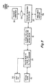
- FIGURE 4 is a simplified flow chart illustrating the logic flow in the command controller for determining the need to be in a first, high-motor-efficiency mode of operation or a second, lower-motor-efficiency mode of operation.
- the logic starts at a START block 510, and flows to a further logic block 512, which represents the reading of the cooling system temperature. From block 512, the logic flows to a decision block 514, which determines if supplemental heat is requested. If supplemental heat is not requested, the logic leaves decision block 514 by the NO output, and returns by way of a logic path 514N to block 512.
- supplemental heat may be requested, so the logic leaves decision block 514 by the YES output, and arrives at a further block 516, which represents reduction in the efficiency of the traction motor. From block 516, the logic flows by way of a block 517, representing reading of the cooling system temperature, to a further decision block 518, which compares the cooling system temperature with a preset standard, which may be variable by the vehicle operator. If the temperature of the cooling system is not at its normal operating temperature, the logic leaves decision block 518 by the NO path, and proceeds back to block 516, to continue the low-efficiency operation. On the other hand, if decision block 518 finds that the cooling system is at its proper operating temperature, the logic exits by the YES output, and proceeds to a block 520, which represents maintenance of the normal or high efficiency operating state of the cooling system.
- valve 318 has been illustrated as being used to control the flow of heat to passenger compartment 316, a flow diverter or other device could be used. While the temperature has been described as being under the control of a feedback system, the control could be open-loop control, as for example control of valve 318 of FIGURE 3 by a vehicle operator, as is common in present-day automobiles. While the arrangement of FIGURE 3 uses two separate heat exchangers 310 and 312, they are thermally coupled, and it is apparent that they may be combined into a single unit if appropriate, or that more than two heat exchangers may be used if desired.
- a hybrid electric vehicle (10) includes a mechanical drive arrangement (40d, 12) for moving the vehicle (10) in response to mechanical drive.
- An electric traction motor (40) is coupled to the mechanical drive arrangement (40d, 12), for, when energized, mechanically driving the mechanical drive arrangement (40d, 12), to thereby drive the vehicle (10).
- the vehicle (10) also includes a store (20) of electrical energy (which may be a traction battery), and a controller (14, 50) coupled to the store (20) of electrical energy and to the traction motor (40), for controllably energizing the traction motor (40).
- the energization of the traction motor (40) causes mechanical drive of the mechanical drive arrangement.
- the vehicle (10) carries fuel, as in a tank (18t).
- a controllable source (16) of electrical energy such as a fuel cell (24) or an internal combustion engine/electric generator (18, 22), is coupled to the source of fuel (18t), and to at least the controller (14, 50), for using the fuel to generate electrical energy for either driving the traction motor (40), storage in the store (20) of electrical energy, or both.
- heat is unavoidably generated.
- the vehicle (10) includes a passenger compartment (316), and a heat exchanger (310, 312) coupled to the passenger compartment (316), to the source (20) of electrical energy, and to the traction motor (40), for controllably coupling the heat to the passenger compartment (316), in order to maintain the passenger compartment comfortably (3160 warm.
- the heat generated by the source (20) of electrical energy and the traction motor (40) may be insufficient to maintain a comfortable temperature in the passenger compartment (316).
- a control arrangement (400) is associated with the controller (14, 50), for operating the traction motor (40) in a first state defining a first range of efficiencies, and for, when necessary to maintain the comfortable temperature in the passenger compartment, operating the traction motor (40) in a second state having a range of efficiencies which is lower than the range of efficiencies of the first state, for thereby generating more heat from the traction motor (40), which additional heat can be made available to the passenger compartment (316).
- the traction motor (40) is an ac motor
- the controller (14, 50) includes a dc-to-ac inverter (28) coupled to the battery (20) and to the ac motor (40), for controllably converting the direct voltage into alternating-current drive for the ac motor (40).
- the control arrangement (14, 50) in this embodiment includes a direct current control arrangement for, in the second state, causing a significant direct current to flow through the ac motor.
- the store (20) of electrical energy includes an electrical battery (20) for producing direct voltage
- the traction motor (40) is an ac induction motor
- the controller (14, 50) includes a dc-to-ac inverter (28) coupled to the battery (20) and to the ac motor (40), for controllably converting the direct voltage into variable-frequency alternating-current drive for the ac motor (40), whereby in the first operating state the induction motor (40) rotates at a frequency which is less than the frequency of the alternating-current drive by a first range of slip frequencies.
- the control arrangement (14, 50) includes an arrangement (400) for operating in a second operating state, in which the slip frequencies occupy a second range, in which the highest frequencies are greater than the highest frequencies of the first range.
Landscapes
- Engineering & Computer Science (AREA)
- Mechanical Engineering (AREA)
- Combustion & Propulsion (AREA)
- Chemical & Material Sciences (AREA)
- Transportation (AREA)
- Sustainable Development (AREA)
- Sustainable Energy (AREA)
- Power Engineering (AREA)
- Life Sciences & Earth Sciences (AREA)
- Physics & Mathematics (AREA)
- Thermal Sciences (AREA)
- Automation & Control Theory (AREA)
- Electric Propulsion And Braking For Vehicles (AREA)
- Hybrid Electric Vehicles (AREA)
- Air-Conditioning For Vehicles (AREA)
- Control Of Vehicle Engines Or Engines For Specific Uses (AREA)
Description
Claims (5)
- A hybrid electric vehicle, comprising
a passenger compartment,
a mechanical drive arrangement (12) for moving said vehicle in response to mechanical drive,
an electric traction motor (40) coupled to said mechanical drive arrangement (12), for, when energized, mechanically driving said mechanical drive arrangement to thereby drive said vehicle,
a store of electrical energy (20),
a controller (14) coupled to said store of electrical energy (20) and to said traction motor (40), for controllably energizing said traction motor, for thereby causing said mechanical drive of said mechanical drive arrangement (12),
a source of fuel (18t),
a controllable source of electrical energy (18,22 or 24) coupled to said source of fuel (18t), and to at least said controller (14), for using said fuel to generate electrical energy for at least one of driving said traction motor (40) and storage in said store of electrical energy (20),
whereby operation of said source of electrical energy (18,22 or 24) and said traction motor (40) unavoidably results in generation of heat and
heat exchanging means coupled to said passenger compartment, to said source of electrical energy (18,22 or 24), and to said traction motor (40), for controllably coupling said heat to said passenger compartment,
whereby during cold weather said heat generated by said source of electrical energy (18,22 or 24) and said traction motor (40) may be insufficient to maintain a comfortable temperature in the passenger compartment
characterized in, that a control means (50) associated with said controller (14) is provided, for operating said traction motor (40) in a first state defining a first range of efficiencies, and for sensing said temperature of said passenger compartment, and for, when necessary to maintain said comfortable temperature, operating said traction motor (40) in a second state having a range of efficiencies which is lower than said range of efficiencies in said first state, for thereby generating more heat from said traction motor, which can be made available to said passenger compartment. - The vehicle according to claim 1 wherein
said store of electrical energy includes an electrical battery (20) for producing direct voltage,
said traction motor (40) is an ac motor and
said controller (14) includes a dc-to-ac inverter (28) coupled to said battery (20) and to said ac motor (40), for controllably converting said direct voltage into alternating-current drive for said ac motor (40)
characterized in, that said control means (50) includes means for causing a significant direct current to flow through said ac motor (40) in said second state. - The vehicle according to claim 1 wherein
said store of electrical energy includes an electrical battery (20) for producing direct voltage and
said traction motor (40) is an ac induction motor,
characterized in, that said controller (14) includes a dc-to-ac inverter (28) coupled to said battery (20) and to said ac motor (40), for controllably converting said direct voltage into variable-frequency alternating-current drive for said ac motor (40), whereby in said first operating state said induction motor (40) rotates at a frequency which is less than the frequency of alternating-current drive by a first range of slip frequencies and
that said control means (50) includes means for, in said second operating state slip frequencies occupy a second range, which the highest frequencies of which are greater than the highest frequencies of said first range. - A method for operating a hybrid electric vehicle having a passenger compartment, wherein said method comprises the steps of
providing a battery (20) on said vehicle,
providing a fuel container (18t) on said vehicle,
on said vehicle, operating one of a fuel cell (24) and an internal-combustion-engine (18) with an electric generator (22) using fuel from said fuel container (18t) to thereby generate electricity for charging said battery (20),
on said vehicle, applying alternating voltage, at an alternating voltage frequency, to a traction motor (40), to thereby generate mechanical energy, whereby said traction motor (40) generates waste heat in an amount dependent upon the efficiency of said traction motor (40),
applying said mechanical energy to drive said vehicle,
transferring heat from at least said traction motor (40) to said passenger compartment and
on said vehicle, controllably converting direct voltage from said battery (20) into said alternating voltage,
characterized in, that the conversion of direct voltage from said battery (20) into said alternating voltage is performed by pulse-width controlling a plurality of power switches at a pulse-width frequency which is greater than said alternating voltage frequency and
that when more heat is needed from said traction motor (40) to aid in heating said passenger compartment, said pulse-width frequency is adjusted relative to said alternating voltage frequency in a manner which results in a direct current through said traction motor (40), which decreases said efficiency of said traction motor(40) in manner which tends to increase the heat output of said traction motor (40). - A method for operating a hybrid electric vehicle having a passenger compartment, wherein said method comprises the steps of
providing a battery (20) on said vehicle,
providing a fuel container (18t) on said vehicle,
on said vehicle, operating one of a fuel cell (24) and an internal-combustion-engine (18) with an electric generator (22) using fuel from said fuel container (18t) to thereby generate electricity for charging said battery (20),
on said vehicle, applying alternating voltage, at an alternating voltage frequency, to a traction motor (40), to thereby generate mechanical energy, whereby said traction motor (40) generates waste heat in an amount dependent upon the efficiency of said traction motor (40),
applying said mechanical energy to drive said vehicle,
transferring heat from at least said traction motor (40) to said passenger compartment and on said vehicle, controllably converting direct voltage from said battery (20) into said alternating voltage at said alternating voltage frequency,
characterized in, that when more heat is needed from said traction motor (40) to aid in heating said passenger compartment, said alternating voltage frequency is adjusted in a manner which results in slip between the rotational frequency of said ac induction traction motor (40) and said alternating voltage frequency, which decreases said efficiency of said traction motor (40) in a manner which tends to increase the heat output of said traction motor (40).
Applications Claiming Priority (4)
| Application Number | Priority Date | Filing Date | Title |
|---|---|---|---|
| US6673597P | 1997-11-21 | 1997-11-21 | |
| US66735P | 1997-11-21 | ||
| US09/039,896 US5950752A (en) | 1997-11-21 | 1998-03-16 | Heating system for a hybrid electric vehicle |
| US39896 | 1998-03-16 |
Publications (3)
| Publication Number | Publication Date |
|---|---|
| EP0917976A2 EP0917976A2 (en) | 1999-05-26 |
| EP0917976A3 EP0917976A3 (en) | 2000-07-26 |
| EP0917976B1 true EP0917976B1 (en) | 2003-07-09 |
Family
ID=26716560
Family Applications (1)
| Application Number | Title | Priority Date | Filing Date |
|---|---|---|---|
| EP98121582A Expired - Lifetime EP0917976B1 (en) | 1997-11-21 | 1998-11-19 | Heating system for a hybrid electric vehicle |
Country Status (8)
| Country | Link |
|---|---|
| US (1) | US5950752A (en) |
| EP (1) | EP0917976B1 (en) |
| JP (3) | JPH11220801A (en) |
| KR (1) | KR100562092B1 (en) |
| CA (1) | CA2254022C (en) |
| DE (1) | DE69816235T2 (en) |
| ES (1) | ES2202717T3 (en) |
| NO (1) | NO985421L (en) |
Cited By (1)
| Publication number | Priority date | Publication date | Assignee | Title |
|---|---|---|---|---|
| JP2014500189A (en) * | 2010-12-24 | 2014-01-09 | ダイムラー・アクチェンゲゼルシャフト | Method for heating the interior of a car |
Families Citing this family (49)
| Publication number | Priority date | Publication date | Assignee | Title |
|---|---|---|---|---|
| IT1296642B1 (en) * | 1997-12-15 | 1999-07-14 | Bitron Spa | POWER SYSTEM OF AN ELECTRONICALLY SWITCHED ELECTRIC MOTOR FOR AIR CONDITIONING DEVICES TO BE INSTALLED INSIDE |
| EP0949095B1 (en) * | 1998-04-07 | 2003-07-02 | The Swatch Group Management Services AG | Device for cooling engines and for heating the interior of a hybrid vehicle |
| US6194851B1 (en) * | 1999-01-27 | 2001-02-27 | Hy-Security Gate, Inc. | Barrier operator system |
| US6362535B1 (en) | 1999-08-11 | 2002-03-26 | Bae Systems | Method and apparatus for after-treatment of hev exhaust |
| US6239502B1 (en) * | 1999-11-22 | 2001-05-29 | Bae Systems Controls | Phase change assisted heat sink |
| JP3804383B2 (en) * | 2000-01-19 | 2006-08-02 | トヨタ自動車株式会社 | Control device for vehicle having fuel cell |
| FR2806666B1 (en) * | 2000-03-21 | 2003-12-12 | Technicatome | PROCESS FOR AIR CONDITIONING A HYBRID SELF-PROPELLED VEHICLE AND VEHICLE USING SUCH A PROCESS |
| DE10022319A1 (en) * | 2000-05-09 | 2001-11-29 | Voith Turbo Kg | Drive unit, in particular electrical drive unit for driving a wheel axle in a transaxle design |
| US6860349B2 (en) * | 2000-05-26 | 2005-03-01 | Honda Giken Kogyo Kabushiki Kaisha | Cooling system for fuel cell powered vehicle and fuel cell powered vehicle employing the same |
| EP1176038A3 (en) * | 2000-07-25 | 2003-05-21 | Robert Bosch Gmbh | Method of controlling temperature in the interior of a motor vehicle |
| US6326765B1 (en) | 2000-10-04 | 2001-12-04 | Vectrix Corporation | Electric scooter with on-board charging system |
| DE10054007A1 (en) * | 2000-11-01 | 2002-06-06 | Xcellsis Gmbh | Motor vehicle with a drive internal combustion engine |
| JP3598975B2 (en) * | 2001-01-19 | 2004-12-08 | 日産自動車株式会社 | Control device for fuel cell vehicle |
| FR2819760B1 (en) * | 2001-01-25 | 2003-09-19 | Renault | METHOD FOR REGULATING THE TEMPERATURE OF A COCKPIT OF A VEHICLE EQUIPPED WITH A FUEL CELL |
| US6455947B1 (en) | 2001-02-14 | 2002-09-24 | Bae Systems Controls, Inc. | Power combining apparatus for hybrid electric vehicle |
| US6865901B2 (en) * | 2002-05-29 | 2005-03-15 | Webasto Thermosysteme International Gmbh | System with an internal combustion engine, a fuel cell and a climate control unit for heating and/or cooling the interior of a motor vehicle and process for the operation thereof |
| US20040188154A1 (en) * | 2003-02-25 | 2004-09-30 | Carlson Grant B. | Addition of fuel cell system into motor vehicle |
| EP1466779A3 (en) * | 2003-04-10 | 2006-09-06 | Hitachi, Ltd. | Motor control device |
| JP2005032039A (en) * | 2003-07-07 | 2005-02-03 | Sony Corp | Electronic device, power management method for electronic device, and power supply device |
| US20060243503A1 (en) * | 2004-02-24 | 2006-11-02 | Carlson Grant B | Addition of fuel cell system into motor vehicle |
| US7818959B2 (en) * | 2004-09-17 | 2010-10-26 | Eaton Corporation | Clean power system |
| US7648785B2 (en) * | 2004-09-17 | 2010-01-19 | Eaton Corporation | Clean power system |
| US8463529B2 (en) | 2004-09-17 | 2013-06-11 | Eaton Corporation | System and method of operating internal combustion engines at fuel rich low-temperature- combustion mode as an on-board reformer for solid oxide fuel cell-powered vehicles |
| JP4066995B2 (en) * | 2004-11-25 | 2008-03-26 | トヨタ自動車株式会社 | Automobile and control method thereof |
| FR2886222B1 (en) * | 2005-05-30 | 2008-12-05 | Giat Ind Sa | DEVICE FOR MANAGING THERMAL ENERGY FOR A VEHICLE |
| US7883809B2 (en) * | 2005-08-03 | 2011-02-08 | GM Global Technology Operations LLC | Rapid startup of a fuel cell power module using motor drive |
| US20080110485A1 (en) * | 2006-11-13 | 2008-05-15 | Vasilantone Michael M | Hybrid automotive vehicle with solar battery charging |
| DE102009000204A1 (en) * | 2009-01-14 | 2010-07-15 | Robert Bosch Gmbh | Electric drive and heating for a vehicle, and method for heating a vehicle |
| US20100218916A1 (en) * | 2009-02-27 | 2010-09-02 | Ford Global Technolgies, Llc | Plug-in hybrid electric vehicle secondary cooling system |
| DE102009053387B4 (en) | 2009-11-14 | 2022-10-20 | Volkswagen Ag | Device and method for heating a passenger compartment of an electrically powered vehicle |
| FR2953793B1 (en) * | 2009-12-15 | 2012-01-20 | Peugeot Citroen Automobiles Sa | MOTORIZATION MANAGEMENT METHOD FOR A HYBRID VEHICLE |
| EP2338718A1 (en) * | 2009-12-23 | 2011-06-29 | VOLK Fahrzeugbau GmbH | Heat exchange system of an industrial truck |
| WO2011108058A1 (en) | 2010-03-01 | 2011-09-09 | トヨタ自動車株式会社 | Electric vehicle and method for controlling same |
| CA2806085A1 (en) * | 2010-07-30 | 2012-02-02 | Automatic Technology (Australia) Pty Ltd | Integrated controller for closure operator unit |
| KR101189581B1 (en) * | 2010-11-17 | 2012-10-11 | 기아자동차주식회사 | Heating control method for fuel cell vehicle |
| FR2972086A1 (en) * | 2011-02-28 | 2012-08-31 | Peugeot Citroen Automobiles Sa | Car, has cooling system for heating passenger compartment and/or certain components of car, and power control circuit including unit to maximize iron loss and joule loss of machine in phases for which rotor of machine is mobile or fixed |
| US8800521B2 (en) * | 2011-12-20 | 2014-08-12 | GM Global Technology Operations LLC | Electric vehicle fluid preheater |
| US8600615B2 (en) * | 2012-02-01 | 2013-12-03 | GM Global Technology Operations LLC | Vehicle cabin warm-up |
| DE102012107016B4 (en) * | 2012-08-01 | 2018-11-22 | Avl Software And Functions Gmbh | Method for operating a heater for a battery of an at least partially and / or temporarily electrically driven motor vehicle |
| DE102012224071A1 (en) * | 2012-12-20 | 2014-06-26 | Siemens Aktiengesellschaft | Heating for electric vehicles and method for their control |
| CN103213473B (en) * | 2013-04-17 | 2016-06-08 | 安徽江淮汽车股份有限公司 | The dual-purpose heating system of water power of a kind of hybrid electric vehicle and control method |
| JP6539264B2 (en) * | 2013-06-28 | 2019-07-03 | ビーワイディー カンパニー リミテッドByd Company Limited | Electric power system for electric vehicle, electric vehicle, and motor controller |
| FR3014062B1 (en) * | 2013-12-03 | 2015-12-11 | Renault Sas | METHOD FOR MANAGING ENERGY IN A HYBRID VEHICLE HAVING DISCRETE REPORTING TRANSMISSION |
| CN103786549B (en) * | 2014-01-09 | 2017-12-08 | 浙江吉利控股集团有限公司 | Motor vehicle driven by mixed power and its air-conditioning system |
| DE102014211447A1 (en) * | 2014-06-16 | 2015-12-17 | Bayerische Motoren Werke Aktiengesellschaft | Method and control device for controlling the heat loss generated by an electric vehicle |
| GB201513549D0 (en) * | 2015-07-31 | 2015-09-16 | Siemens Ag | Inverter |
| DE102015225103A1 (en) * | 2015-12-14 | 2017-06-14 | Robert Bosch Gmbh | Powertrain for a vehicle |
| FR3056362B1 (en) * | 2016-09-21 | 2018-10-05 | Renault S.A.S | METHOD FOR CONTROLLING AN ELECTRIC MOTOR OF A HYBRID VEHICLE |
| CN108839577B (en) * | 2018-06-20 | 2021-07-27 | 安徽安凯汽车股份有限公司 | Hydrogen fuel cell series-parallel hybrid power system and passenger car |
Family Cites Families (19)
| Publication number | Priority date | Publication date | Assignee | Title |
|---|---|---|---|---|
| US4331209A (en) * | 1980-02-29 | 1982-05-25 | Clark Equipment Company | Ventilation system for electric vehicles |
| SE448741B (en) * | 1980-12-23 | 1987-03-16 | Asea Ab | METHODS AND DEVICES FOR TURPED DESULATOR DESCRIPTION |
| US4364444A (en) * | 1981-01-16 | 1982-12-21 | Drexel Industries, Inc. | Temperature regulation system for electric vehicles |
| JPS57131305U (en) * | 1981-02-13 | 1982-08-16 | ||
| JPS63140690A (en) * | 1986-05-14 | 1988-06-13 | Shigeru Terada | Method for controlling speed of ac motor |
| JPH02155827A (en) * | 1988-12-05 | 1990-06-14 | Toyota Motor Corp | Heater for electric car |
| JPH02227316A (en) * | 1989-02-28 | 1990-09-10 | Toyota Motor Corp | Heater for electric automobile |
| JP2920941B2 (en) * | 1989-07-11 | 1999-07-19 | 松下電器産業株式会社 | Motor control device |
| GB9116661D0 (en) * | 1991-08-01 | 1991-09-18 | The Technology Partnership Ltd | Vehicle cooling system |
| JPH05131848A (en) * | 1991-11-15 | 1993-05-28 | Toyota Motor Corp | Hybrid car driving system control device |
| JPH05344606A (en) * | 1992-06-04 | 1993-12-24 | Seiko Epson Corp | Cooling system of electric automobile |
| US5255733A (en) * | 1992-08-10 | 1993-10-26 | Ford Motor Company | Hybird vehicle cooling system |
| US5291960A (en) * | 1992-11-30 | 1994-03-08 | Ford Motor Company | Hybrid electric vehicle regenerative braking energy recovery system |
| JPH07329544A (en) * | 1994-06-07 | 1995-12-19 | Nippondenso Co Ltd | Air conditioner for automobile |
| DE9413500U1 (en) * | 1994-08-22 | 1994-10-13 | Irmscher Gmbh | Automobile, especially for private local transport |
| US5739664A (en) * | 1996-02-05 | 1998-04-14 | Ford Global Technologies, Inc. | Induction motor drive controller |
| JP3484871B2 (en) * | 1996-04-24 | 2004-01-06 | 株式会社デンソー | Vehicle air conditioner |
| DE19649710C2 (en) * | 1996-11-30 | 1999-04-15 | Mc Micro Compact Car Ag | Device for heating the passenger compartment of an electric vehicle |
| US5850132A (en) * | 1997-07-02 | 1998-12-15 | Allin-Bradley Company, Llc | Apparatus used with AC motors for compensating for turn on delay errors |
-
1998
- 1998-03-16 US US09/039,896 patent/US5950752A/en not_active Expired - Lifetime
- 1998-11-12 CA CA002254022A patent/CA2254022C/en not_active Expired - Lifetime
- 1998-11-19 ES ES98121582T patent/ES2202717T3/en not_active Expired - Lifetime
- 1998-11-19 DE DE69816235T patent/DE69816235T2/en not_active Expired - Lifetime
- 1998-11-19 EP EP98121582A patent/EP0917976B1/en not_active Expired - Lifetime
- 1998-11-20 NO NO985421A patent/NO985421L/en not_active Application Discontinuation
- 1998-11-20 JP JP10330815A patent/JPH11220801A/en active Pending
- 1998-11-21 KR KR1019980050080A patent/KR100562092B1/en not_active Expired - Fee Related
-
2010
- 2010-03-24 JP JP2010067898A patent/JP2010208630A/en active Pending
-
2011
- 2011-09-30 JP JP2011216420A patent/JP2012066817A/en active Pending
Cited By (1)
| Publication number | Priority date | Publication date | Assignee | Title |
|---|---|---|---|---|
| JP2014500189A (en) * | 2010-12-24 | 2014-01-09 | ダイムラー・アクチェンゲゼルシャフト | Method for heating the interior of a car |
Also Published As
| Publication number | Publication date |
|---|---|
| US5950752A (en) | 1999-09-14 |
| KR100562092B1 (en) | 2006-06-14 |
| JP2012066817A (en) | 2012-04-05 |
| JPH11220801A (en) | 1999-08-10 |
| DE69816235D1 (en) | 2003-08-14 |
| ES2202717T3 (en) | 2004-04-01 |
| JP2010208630A (en) | 2010-09-24 |
| NO985421D0 (en) | 1998-11-20 |
| DE69816235T2 (en) | 2004-04-22 |
| EP0917976A3 (en) | 2000-07-26 |
| CA2254022C (en) | 2006-10-24 |
| CA2254022A1 (en) | 1999-05-21 |
| NO985421L (en) | 1999-05-25 |
| EP0917976A2 (en) | 1999-05-26 |
| KR19990045481A (en) | 1999-06-25 |
Similar Documents
| Publication | Publication Date | Title |
|---|---|---|
| CA2254022C (en) | Heating system for a hybrid electric vehicle | |
| AU2008247961B2 (en) | Propulsion system | |
| US9849871B2 (en) | Electric vehicle opportunistic charging systems and methods | |
| US9987944B2 (en) | Electric vehicle opportunistic charging systems and methods | |
| CN103124651B (en) | Hybrid power system | |
| US5929595A (en) | Hybrid electric vehicle with traction motor drive allocated between battery and auxiliary source depending upon battery charge state | |
| US5910722A (en) | Hybrid electric vehicle with reduced auxiliary power to batteries during regenerative braking | |
| US6116368A (en) | Electric vehicle with battery regeneration dependent on battery charge state | |
| AU2008247963B2 (en) | Electric drive vehicle retrofit system and associated method | |
| US5568023A (en) | Electric power train control | |
| US5941328A (en) | Electric vehicle with variable efficiency regenerative braking depending upon battery charge state | |
| EP2146863B1 (en) | Method of operating a propulsion system | |
| AU2011325855B2 (en) | AC drive system for a vehicle | |
| JPH08508392A (en) | Track-unconstrained automobile with electric motor | |
| US20150197238A1 (en) | Hybrid vehicle control unit | |
| EP2150433A1 (en) | Heating system for use in a vehicle | |
| MXPA98009715A (en) | Heating system for a hybrid electric vehicle | |
| AU2014246607B2 (en) | Method of operating propulsion system |
Legal Events
| Date | Code | Title | Description |
|---|---|---|---|
| PUAI | Public reference made under article 153(3) epc to a published international application that has entered the european phase |
Free format text: ORIGINAL CODE: 0009012 |
|
| AK | Designated contracting states |
Kind code of ref document: A2 Designated state(s): BE DE ES FR GB IT NL SE |
|
| AX | Request for extension of the european patent |
Free format text: AL;LT;LV;MK;RO;SI |
|
| PUAL | Search report despatched |
Free format text: ORIGINAL CODE: 0009013 |
|
| AK | Designated contracting states |
Kind code of ref document: A3 Designated state(s): AT BE CH CY DE DK ES FI FR GB GR IE IT LI LU MC NL PT SE |
|
| AX | Request for extension of the european patent |
Free format text: AL;LT;LV;MK;RO;SI |
|
| 17P | Request for examination filed |
Effective date: 20001127 |
|
| AKX | Designation fees paid |
Free format text: BE DE ES FR GB IT NL SE |
|
| RAP1 | Party data changed (applicant data changed or rights of an application transferred) |
Owner name: BAE SYSTEMS CONTROLS, INC. |
|
| 17Q | First examination report despatched |
Effective date: 20020723 |
|
| GRAH | Despatch of communication of intention to grant a patent |
Free format text: ORIGINAL CODE: EPIDOS IGRA |
|
| GRAH | Despatch of communication of intention to grant a patent |
Free format text: ORIGINAL CODE: EPIDOS IGRA |
|
| GRAA | (expected) grant |
Free format text: ORIGINAL CODE: 0009210 |
|
| AK | Designated contracting states |
Designated state(s): BE DE ES FR GB IT NL SE |
|
| REG | Reference to a national code |
Ref country code: GB Ref legal event code: FG4D |
|
| REF | Corresponds to: |
Ref document number: 69816235 Country of ref document: DE Date of ref document: 20030814 Kind code of ref document: P |
|
| REG | Reference to a national code |
Ref country code: SE Ref legal event code: TRGR |
|
| ET | Fr: translation filed | ||
| REG | Reference to a national code |
Ref country code: ES Ref legal event code: FG2A Ref document number: 2202717 Country of ref document: ES Kind code of ref document: T3 |
|
| PLBE | No opposition filed within time limit |
Free format text: ORIGINAL CODE: 0009261 |
|
| STAA | Information on the status of an ep patent application or granted ep patent |
Free format text: STATUS: NO OPPOSITION FILED WITHIN TIME LIMIT |
|
| 26N | No opposition filed |
Effective date: 20040414 |
|
| PGFP | Annual fee paid to national office [announced via postgrant information from national office to epo] |
Ref country code: SE Payment date: 20141128 Year of fee payment: 17 |
|
| REG | Reference to a national code |
Ref country code: FR Ref legal event code: PLFP Year of fee payment: 18 |
|
| PG25 | Lapsed in a contracting state [announced via postgrant information from national office to epo] |
Ref country code: IT Free format text: LAPSE BECAUSE OF NON-PAYMENT OF DUE FEES Effective date: 20151119 |
|
| PG25 | Lapsed in a contracting state [announced via postgrant information from national office to epo] |
Ref country code: SE Free format text: LAPSE BECAUSE OF NON-PAYMENT OF DUE FEES Effective date: 20151120 |
|
| REG | Reference to a national code |
Ref country code: FR Ref legal event code: PLFP Year of fee payment: 19 |
|
| PGFP | Annual fee paid to national office [announced via postgrant information from national office to epo] |
Ref country code: FR Payment date: 20161123 Year of fee payment: 19 Ref country code: NL Payment date: 20161126 Year of fee payment: 19 Ref country code: GB Payment date: 20161128 Year of fee payment: 19 Ref country code: DE Payment date: 20161123 Year of fee payment: 19 |
|
| PGFP | Annual fee paid to national office [announced via postgrant information from national office to epo] |
Ref country code: ES Payment date: 20161128 Year of fee payment: 19 Ref country code: BE Payment date: 20161128 Year of fee payment: 19 |
|
| PG25 | Lapsed in a contracting state [announced via postgrant information from national office to epo] |
Ref country code: IT Free format text: LAPSE BECAUSE OF NON-PAYMENT OF DUE FEES Effective date: 20151119 |
|
| PGFP | Annual fee paid to national office [announced via postgrant information from national office to epo] |
Ref country code: IT Payment date: 20161124 Year of fee payment: 19 |
|
| PGRI | Patent reinstated in contracting state [announced from national office to epo] |
Ref country code: IT Effective date: 20170710 |
|
| REG | Reference to a national code |
Ref country code: DE Ref legal event code: R119 Ref document number: 69816235 Country of ref document: DE |
|
| REG | Reference to a national code |
Ref country code: NL Ref legal event code: MM Effective date: 20171201 |
|
| GBPC | Gb: european patent ceased through non-payment of renewal fee |
Effective date: 20171119 |
|
| REG | Reference to a national code |
Ref country code: FR Ref legal event code: ST Effective date: 20180731 Ref country code: BE Ref legal event code: MM Effective date: 20171130 |
|
| PG25 | Lapsed in a contracting state [announced via postgrant information from national office to epo] |
Ref country code: IT Free format text: LAPSE BECAUSE OF NON-PAYMENT OF DUE FEES Effective date: 20171119 Ref country code: DE Free format text: LAPSE BECAUSE OF NON-PAYMENT OF DUE FEES Effective date: 20180602 Ref country code: FR Free format text: LAPSE BECAUSE OF NON-PAYMENT OF DUE FEES Effective date: 20171130 Ref country code: NL Free format text: LAPSE BECAUSE OF NON-PAYMENT OF DUE FEES Effective date: 20171201 |
|
| PG25 | Lapsed in a contracting state [announced via postgrant information from national office to epo] |
Ref country code: BE Free format text: LAPSE BECAUSE OF NON-PAYMENT OF DUE FEES Effective date: 20171130 Ref country code: GB Free format text: LAPSE BECAUSE OF NON-PAYMENT OF DUE FEES Effective date: 20171119 |
|
| REG | Reference to a national code |
Ref country code: ES Ref legal event code: FD2A Effective date: 20181226 |
|
| PG25 | Lapsed in a contracting state [announced via postgrant information from national office to epo] |
Ref country code: ES Free format text: LAPSE BECAUSE OF NON-PAYMENT OF DUE FEES Effective date: 20171120 |