EP0917756B1 - Rotary electrical machines - Google Patents
Rotary electrical machines Download PDFInfo
- Publication number
- EP0917756B1 EP0917756B1 EP97934661A EP97934661A EP0917756B1 EP 0917756 B1 EP0917756 B1 EP 0917756B1 EP 97934661 A EP97934661 A EP 97934661A EP 97934661 A EP97934661 A EP 97934661A EP 0917756 B1 EP0917756 B1 EP 0917756B1
- Authority
- EP
- European Patent Office
- Prior art keywords
- ring
- retention
- rotor
- retention ring
- mandrel
- Prior art date
- Legal status (The legal status is an assumption and is not a legal conclusion. Google has not performed a legal analysis and makes no representation as to the accuracy of the status listed.)
- Expired - Lifetime
Links
- 230000014759 maintenance of location Effects 0.000 claims abstract description 31
- 238000000034 method Methods 0.000 claims description 15
- 230000001419 dependent effect Effects 0.000 claims 1
- 241000239290 Araneae Species 0.000 description 2
- 238000003475 lamination Methods 0.000 description 2
- 239000002184 metal Substances 0.000 description 2
- OKTJSMMVPCPJKN-UHFFFAOYSA-N Carbon Chemical compound [C] OKTJSMMVPCPJKN-UHFFFAOYSA-N 0.000 description 1
- 229910052799 carbon Inorganic materials 0.000 description 1
- 238000012986 modification Methods 0.000 description 1
- 230000004048 modification Effects 0.000 description 1
Images

Classifications
-
- H—ELECTRICITY
- H02—GENERATION; CONVERSION OR DISTRIBUTION OF ELECTRIC POWER
- H02K—DYNAMO-ELECTRIC MACHINES
- H02K1/00—Details of the magnetic circuit
- H02K1/06—Details of the magnetic circuit characterised by the shape, form or construction
- H02K1/22—Rotating parts of the magnetic circuit
- H02K1/27—Rotor cores with permanent magnets
- H02K1/2706—Inner rotors
- H02K1/2713—Inner rotors the magnetisation axis of the magnets being axial, e.g. claw-pole type
-
- H—ELECTRICITY
- H02—GENERATION; CONVERSION OR DISTRIBUTION OF ELECTRIC POWER
- H02K—DYNAMO-ELECTRIC MACHINES
- H02K15/00—Processes or apparatus specially adapted for manufacturing, assembling, maintaining or repairing of dynamo-electric machines
- H02K15/02—Processes or apparatus specially adapted for manufacturing, assembling, maintaining or repairing of dynamo-electric machines of stator or rotor bodies
- H02K15/03—Processes or apparatus specially adapted for manufacturing, assembling, maintaining or repairing of dynamo-electric machines of stator or rotor bodies having permanent magnets
Definitions
- the present invention relates to a rotor for a rotary electrical machine such as an electrical generator or electric motor.
- British Patent Specification GB 2 222 031 A describes an axial field electrical generator capable of operation at very high speeds.
- This document describes an axial field electrical generator having a disc rotor with a ring of permanent magnet segments equiangularly spaced around a hub. Engagement with the hub is maintained by means of a pre-stressed hoop. The hoop is formed initially as a push fit and stressed during assembly by expanding the hub by forcing into it, an oversize boss.
- US-4,918,802 describes a system for applying a plurality of permanent magnet segments and an outer sleeve or cylinder onto the laminations of a rotating electric machine. This involves mounting the permanent magnet section and sleeve assembly onto a mandrel which is then driven up a tapered shaft so as to expand the magnet sections before they are driven off the mandrel and onto the laminations.
- a method of applying a retention ring to a disc rotor assembly comprising a plurality of substantially equiangularly spaced magnets, characterized by the method comprising mounting the retention ring on a slidable support means and expanding the retention ring by driving the retention ring and support means over a tapered mandrel and onto a rim of the rotor assembly.
- the complete rotor assembly may be used in any kind of electrical machine which utilizes a disc-type rotor, for example as described in GB 2 222 031 A or in the applicants' co-pending UK patent application No. 9123576.2 (GB 2 261 327 A).
- a plurality of the rotors are spaced apart along a drive shaft, interspersed by thin annular stators.
- the magnet Prior to fitment of the retention ring, it is preferred for the magnet to be maintained in position on a hub of the rotor by a temporary retention means, for example a temporary holding ring located over the rim of the rotor. It is also preferred to provide a second (outer) containment ring slidably located over the temporary holding ring, outside the tapered mandrel by means of push fit. When the retention ring is driven over the mandrel, the retention ring can then displace the outer containment ring so that the retention ring grips the temporary holding ring, and hence the rim of the rotor, through the mandrel by means of interference fit.
- a temporary retention means for example a temporary holding ring located over the rim of the rotor.
- a second (outer) containment ring slidably located over the temporary holding ring, outside the tapered mandrel by means of push fit.
- the slidable support means is preferably a slidable support ring.
- the temporary retention ring and slidable support ring can be machined smooth so that they do not obstruct the rotor in use.
- the slidable support ring is preferably rested on a driver means such as a hollow driver cup partially surrounding the mandrel.
- a driver means such as a hollow driver cup partially surrounding the mandrel.
- the ring and driver means is acted upon by one part of a ram, for example mechanical or hydraulic, and a second part of the ram acts on the mandrel.
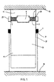
- a retention ring 1 preferably wound from carbon fibres, is to be fitted over a disc rotor 3 having a rim 5.
- the rotor comprises a plurality of substantially equi-angularly spaced magnets fitted on a spider 9.
- the rotor prior to assembly the rotor is located within an upper (wider) part 11 of a tapered mandrel 13.
- the upper part of the mandrel is in contact with one half 15 of a mechanical or hydraulic ram operated press.
- a lower (narrower) part 17 of the mandrel faces a second half 19 of the ram, spaced apart therefrom.
- the retention ring 1 is supported concentrically on the mandrel 13 by means of a slidable concentric metal support ring 21 over which it is located by means of a push fit. Initially, the retention ring and support ring are a loose fit over the mandrel, approximately two thirds down the length thereof.
- the magnets of the rotor are held on the spider 9 by means of a temporary holding inner metal ring 23 also concentric with the mandrel.
- a containment ring 25 outside the mandrel surrounds the inner ring 23 and the rim 5 of the rotor. The containment ring 25 prevents the inner ring 23 from buckling as the retention ring and support ring are driven over it, as described below.
- the support ring 21 is supported by a hollow driver cup 27 surrounding the lower part 17 of the mandrel.
- the base 29 of the driver cup is in direct contact with the second half 19 of the ram.
- actuation of the ram to bring the two halves 15, 19 of the ram closer together causes the support ring 21 and with it the retention ring 1, to travel over the mandrel 14 towards the wider part 11 until the containment ring is upwardly displaced.
- the containment ring is dimensioned to slide freely over the wider part 11 in order not to impede positioning of the retainment ring 1 over the rim 5.
- the retention ring 1 and support ring 21 then grip the inner ring and rim 5 of the rotor through the mandrel.
- the assembled rotor is then cut free of the mandrel and support ring 21 and inner ring 23 are machined down prior to assembly of the rotor into an electrical machine so that the rotor does not have protrusions which would interfere with the stator(s) thereof.
Landscapes
- Engineering & Computer Science (AREA)
- Power Engineering (AREA)
- Manufacturing & Machinery (AREA)
- Permanent Field Magnets Of Synchronous Machinery (AREA)
- Manufacture Of Motors, Generators (AREA)
- Reciprocating, Oscillating Or Vibrating Motors (AREA)
- Insulation, Fastening Of Motor, Generator Windings (AREA)
- Iron Core Of Rotating Electric Machines (AREA)
- Permanent Magnet Type Synchronous Machine (AREA)
- Fish Paste Products (AREA)
- Forklifts And Lifting Vehicles (AREA)
- Confectionery (AREA)
Abstract
Description
Claims (11)
- A method of applying a retention ring (1) to a disc rotor assembly (3) comprising a plurality of substantially equiangularly spaced magnets (7), characterized by the method comprising mounting the retention ring on a slidable support means (21) and expanding the retention ring by driving the retention ring and support means (21) over a tapered mandrel (17) and onto a rim (5) of the rotor assembly.
- A method according to claim 1, wherein the magnets are maintained in position on a hub of the rotor prior to fitment of the retention ring by temporary retention means (23, 25).
- A method according to claim 2, wherein the temporary retention means comprises a temporary holding ring (23) located over the rim of the rotor and an outer containment ring (25) slidably located over the temporary holding ring.
- A method according to claim 3, wherein the retention ring displaces the outer containment ring so that the retention ring grips the temporary holding ring by interference fit
- A method according to any one of claims 1 to 4, wherein the slidable support means is a slidable support ring.
- A method according to claim 5, wherein the slidable support ring is driven over the rotor to be trapped between the rotor rim and the retention ring.
- A method according to claim 5, when dependent on claim 3, wherein after assembly, the rotor is removed from the mandrel and the temporary holding ring and slidable support ring are machined smooth.
- A method according to any preceding claim, wherein the retention ring is driven over the tapered mandrel by ram means (19).
- A method according to claim 8, wherein the retention ring is connected to the ram means by driver means (29).
- A method according to claim 9, wherein the driver means is arranged to act on the slidable support means.
- A method according to claim 8 or claim 9, wherein the ram means is a mechanical or hydraulic ram.
Applications Claiming Priority (3)
| Application Number | Priority Date | Filing Date | Title |
|---|---|---|---|
| GB9616602 | 1996-08-07 | ||
| GB9616602A GB2316812A (en) | 1996-08-07 | 1996-08-07 | Rotary electric machines having disk rotor retention ring |
| PCT/GB1997/002117 WO1998006165A1 (en) | 1996-08-07 | 1997-08-05 | Rotary electrical machines |
Publications (2)
| Publication Number | Publication Date |
|---|---|
| EP0917756A1 EP0917756A1 (en) | 1999-05-26 |
| EP0917756B1 true EP0917756B1 (en) | 2003-10-22 |
Family
ID=10798166
Family Applications (1)
| Application Number | Title | Priority Date | Filing Date |
|---|---|---|---|
| EP97934661A Expired - Lifetime EP0917756B1 (en) | 1996-08-07 | 1997-08-05 | Rotary electrical machines |
Country Status (9)
| Country | Link |
|---|---|
| EP (1) | EP0917756B1 (en) |
| JP (1) | JP2001500352A (en) |
| AT (1) | ATE252780T1 (en) |
| AU (1) | AU3780397A (en) |
| CA (1) | CA2262630C (en) |
| DE (1) | DE69725727T2 (en) |
| GB (1) | GB2316812A (en) |
| ID (1) | ID18646A (en) |
| WO (1) | WO1998006165A1 (en) |
Families Citing this family (1)
| Publication number | Priority date | Publication date | Assignee | Title |
|---|---|---|---|---|
| DE102007014192A1 (en) * | 2007-03-24 | 2008-06-05 | Täubner, Frank, Dr. | Running device producing method for electrical machine, involves polishing magnets such that forcing of bandage is effected and is removed after pressing, where magnets are arranged in outer circumference of runner package device |
Family Cites Families (6)
| Publication number | Priority date | Publication date | Assignee | Title |
|---|---|---|---|---|
| US4759116A (en) * | 1983-11-03 | 1988-07-26 | General Electric Company | Method of applying containment shroud on permanent magnet rotors |
| FR2632788B1 (en) * | 1988-06-08 | 1995-07-13 | Gen Electric | PERMANENT MAGNET ROTORS, MANUFACTURING METHODS AND DEVICES |
| US5144735A (en) * | 1988-06-08 | 1992-09-08 | General Electric Company | Apparatus for assembling a permanent magnet rotor |
| GB8817760D0 (en) * | 1988-07-26 | 1988-09-01 | Rolls Royce Plc | Electrical power generator |
| US4918802A (en) * | 1989-02-06 | 1990-04-24 | Franklin Electric Co., Inc. | Method and apparatus for making permanent magnet rotors |
| GB2299217B (en) * | 1995-03-23 | 1999-07-07 | Aisin Seiki | Method of assembling a permanent magnet rotor |
-
1996
- 1996-08-07 GB GB9616602A patent/GB2316812A/en not_active Withdrawn
-
1997
- 1997-08-05 AU AU37803/97A patent/AU3780397A/en not_active Abandoned
- 1997-08-05 DE DE69725727T patent/DE69725727T2/en not_active Expired - Fee Related
- 1997-08-05 JP JP10507735A patent/JP2001500352A/en active Pending
- 1997-08-05 WO PCT/GB1997/002117 patent/WO1998006165A1/en not_active Ceased
- 1997-08-05 AT AT97934661T patent/ATE252780T1/en not_active IP Right Cessation
- 1997-08-05 EP EP97934661A patent/EP0917756B1/en not_active Expired - Lifetime
- 1997-08-05 CA CA002262630A patent/CA2262630C/en not_active Expired - Fee Related
- 1997-08-06 ID IDP972730A patent/ID18646A/en unknown
Also Published As
| Publication number | Publication date |
|---|---|
| GB2316812A (en) | 1998-03-04 |
| CA2262630A1 (en) | 1998-02-12 |
| AU3780397A (en) | 1998-02-25 |
| DE69725727D1 (en) | 2003-11-27 |
| ATE252780T1 (en) | 2003-11-15 |
| WO1998006165A1 (en) | 1998-02-12 |
| JP2001500352A (en) | 2001-01-09 |
| GB9616602D0 (en) | 1996-09-25 |
| CA2262630C (en) | 2005-08-02 |
| EP0917756A1 (en) | 1999-05-26 |
| ID18646A (en) | 1998-04-30 |
| DE69725727T2 (en) | 2004-07-29 |
Similar Documents
| Publication | Publication Date | Title |
|---|---|---|
| US6195869B1 (en) | Method of applying a retention ring to a disc rotor assembly | |
| US4918802A (en) | Method and apparatus for making permanent magnet rotors | |
| US4970424A (en) | Rotor construction for high speed induction motor | |
| US4741098A (en) | Device for inserting prewound coils in the cavities of a stator of a dynamo-electric machine and apparatus using such a device | |
| US6265802B1 (en) | Laminated rotor assembly and method for a dynamoelectric machine | |
| EP0136584B1 (en) | Rotor for rotary machine | |
| US20080315714A1 (en) | Electrical Rotating Machine Comprising an Intermediate Sleeve Interposed Between the Shaft and the Polar Wheels and Method for Making the Rotor | |
| BR9807031A (en) | Improvement on high speed rotor shafts | |
| US6448674B1 (en) | Drive system | |
| CA2262630C (en) | Rotary electrical machines | |
| ATE74241T1 (en) | EDDY CURRENT BRAKE FOR BRAKING MOTOR VEHICLES. | |
| CN223052894U (en) | Current transmission device for a rotor of an electric machine, and electric machine | |
| EP0101252A3 (en) | A punch and winding machine | |
| EP0248912B1 (en) | Rotor for built-in motor | |
| JP2865562B2 (en) | Method and apparatus for coating rotor magnet | |
| CN113119025B (en) | Fixed rotating seat | |
| US4196366A (en) | Synchronous motor | |
| JP3299113B2 (en) | Method and apparatus for coating rotor magnet | |
| JPH11136887A (en) | Rotating electric machine rotor | |
| US5933939A (en) | Process for producing a commutator of a rotating machine | |
| KR930006284Y1 (en) | Rotor with premanent magnet of synchronous motor | |
| EP0905865A3 (en) | Method of assembling magnetic disk driving motor | |
| US2454955A (en) | Rotor for electric motors and method of making the same | |
| AU8070887A (en) | A machine for winding a rotor for a rotating electrical machine | |
| CA2023491C (en) | Making rotor and stator pole assemblies |
Legal Events
| Date | Code | Title | Description |
|---|---|---|---|
| PUAI | Public reference made under article 153(3) epc to a published international application that has entered the european phase |
Free format text: ORIGINAL CODE: 0009012 |
|
| 17P | Request for examination filed |
Effective date: 19990304 |
|
| AK | Designated contracting states |
Kind code of ref document: A1 Designated state(s): AT BE CH DE DK ES FI FR GB GR IE IT LI LU MC NL PT SE |
|
| RAP1 | Party data changed (applicant data changed or rights of an application transferred) |
Owner name: THE TURBO GENSET COMPANY LIMITED |
|
| 17Q | First examination report despatched |
Effective date: 20010613 |
|
| RAP1 | Party data changed (applicant data changed or rights of an application transferred) |
Owner name: THE TURBO GENSET COMPANY LIMITED |
|
| GRAH | Despatch of communication of intention to grant a patent |
Free format text: ORIGINAL CODE: EPIDOS IGRA |
|
| GRAS | Grant fee paid |
Free format text: ORIGINAL CODE: EPIDOSNIGR3 |
|
| GRAA | (expected) grant |
Free format text: ORIGINAL CODE: 0009210 |
|
| AK | Designated contracting states |
Kind code of ref document: B1 Designated state(s): AT BE CH DE DK ES FI FR GB GR IE IT LI LU MC NL PT SE |
|
| PG25 | Lapsed in a contracting state [announced via postgrant information from national office to epo] |
Ref country code: NL Free format text: LAPSE BECAUSE OF FAILURE TO SUBMIT A TRANSLATION OF THE DESCRIPTION OR TO PAY THE FEE WITHIN THE PRESCRIBED TIME-LIMIT Effective date: 20031022 Ref country code: LI Free format text: LAPSE BECAUSE OF FAILURE TO SUBMIT A TRANSLATION OF THE DESCRIPTION OR TO PAY THE FEE WITHIN THE PRESCRIBED TIME-LIMIT Effective date: 20031022 Ref country code: FI Free format text: LAPSE BECAUSE OF FAILURE TO SUBMIT A TRANSLATION OF THE DESCRIPTION OR TO PAY THE FEE WITHIN THE PRESCRIBED TIME-LIMIT Effective date: 20031022 Ref country code: CH Free format text: LAPSE BECAUSE OF FAILURE TO SUBMIT A TRANSLATION OF THE DESCRIPTION OR TO PAY THE FEE WITHIN THE PRESCRIBED TIME-LIMIT Effective date: 20031022 Ref country code: BE Free format text: LAPSE BECAUSE OF FAILURE TO SUBMIT A TRANSLATION OF THE DESCRIPTION OR TO PAY THE FEE WITHIN THE PRESCRIBED TIME-LIMIT Effective date: 20031022 Ref country code: AT Free format text: LAPSE BECAUSE OF FAILURE TO SUBMIT A TRANSLATION OF THE DESCRIPTION OR TO PAY THE FEE WITHIN THE PRESCRIBED TIME-LIMIT Effective date: 20031022 |
|
| REG | Reference to a national code |
Ref country code: GB Ref legal event code: FG4D |
|
| REG | Reference to a national code |
Ref country code: CH Ref legal event code: EP |
|
| REG | Reference to a national code |
Ref country code: IE Ref legal event code: FG4D |
|
| REF | Corresponds to: |
Ref document number: 69725727 Country of ref document: DE Date of ref document: 20031127 Kind code of ref document: P |
|
| PG25 | Lapsed in a contracting state [announced via postgrant information from national office to epo] |
Ref country code: GR Free format text: LAPSE BECAUSE OF FAILURE TO SUBMIT A TRANSLATION OF THE DESCRIPTION OR TO PAY THE FEE WITHIN THE PRESCRIBED TIME-LIMIT Effective date: 20040122 Ref country code: DK Free format text: LAPSE BECAUSE OF FAILURE TO SUBMIT A TRANSLATION OF THE DESCRIPTION OR TO PAY THE FEE WITHIN THE PRESCRIBED TIME-LIMIT Effective date: 20040122 |
|
| PG25 | Lapsed in a contracting state [announced via postgrant information from national office to epo] |
Ref country code: ES Free format text: LAPSE BECAUSE OF FAILURE TO SUBMIT A TRANSLATION OF THE DESCRIPTION OR TO PAY THE FEE WITHIN THE PRESCRIBED TIME-LIMIT Effective date: 20040202 |
|
| REG | Reference to a national code |
Ref country code: SE Ref legal event code: TRGR |
|
| NLV1 | Nl: lapsed or annulled due to failure to fulfill the requirements of art. 29p and 29m of the patents act | ||
| REG | Reference to a national code |
Ref country code: CH Ref legal event code: PL |
|
| ET | Fr: translation filed | ||
| PG25 | Lapsed in a contracting state [announced via postgrant information from national office to epo] |
Ref country code: LU Free format text: LAPSE BECAUSE OF NON-PAYMENT OF DUE FEES Effective date: 20040805 Ref country code: IE Free format text: LAPSE BECAUSE OF NON-PAYMENT OF DUE FEES Effective date: 20040805 |
|
| PG25 | Lapsed in a contracting state [announced via postgrant information from national office to epo] |
Ref country code: SE Free format text: LAPSE BECAUSE OF NON-PAYMENT OF DUE FEES Effective date: 20040806 |
|
| PLBE | No opposition filed within time limit |
Free format text: ORIGINAL CODE: 0009261 |
|
| STAA | Information on the status of an ep patent application or granted ep patent |
Free format text: STATUS: NO OPPOSITION FILED WITHIN TIME LIMIT |
|
| PG25 | Lapsed in a contracting state [announced via postgrant information from national office to epo] |
Ref country code: MC Free format text: LAPSE BECAUSE OF NON-PAYMENT OF DUE FEES Effective date: 20040831 |
|
| 26N | No opposition filed |
Effective date: 20040723 |
|
| EUG | Se: european patent has lapsed | ||
| REG | Reference to a national code |
Ref country code: IE Ref legal event code: MM4A |
|
| PGFP | Annual fee paid to national office [announced via postgrant information from national office to epo] |
Ref country code: DE Payment date: 20050728 Year of fee payment: 9 |
|
| PGFP | Annual fee paid to national office [announced via postgrant information from national office to epo] |
Ref country code: FR Payment date: 20050809 Year of fee payment: 9 |
|
| PGFP | Annual fee paid to national office [announced via postgrant information from national office to epo] |
Ref country code: IT Payment date: 20060831 Year of fee payment: 10 |
|
| PG25 | Lapsed in a contracting state [announced via postgrant information from national office to epo] |
Ref country code: DE Free format text: LAPSE BECAUSE OF NON-PAYMENT OF DUE FEES Effective date: 20070301 |
|
| REG | Reference to a national code |
Ref country code: FR Ref legal event code: ST Effective date: 20070430 |
|
| PG25 | Lapsed in a contracting state [announced via postgrant information from national office to epo] |
Ref country code: PT Free format text: LAPSE BECAUSE OF NON-PAYMENT OF DUE FEES Effective date: 20040322 |
|
| PGFP | Annual fee paid to national office [announced via postgrant information from national office to epo] |
Ref country code: GB Payment date: 20070801 Year of fee payment: 11 |
|
| PG25 | Lapsed in a contracting state [announced via postgrant information from national office to epo] |
Ref country code: FR Free format text: LAPSE BECAUSE OF NON-PAYMENT OF DUE FEES Effective date: 20060831 |
|
| GBPC | Gb: european patent ceased through non-payment of renewal fee |
Effective date: 20080805 |
|
| PG25 | Lapsed in a contracting state [announced via postgrant information from national office to epo] |
Ref country code: IT Free format text: LAPSE BECAUSE OF NON-PAYMENT OF DUE FEES Effective date: 20070805 |
|
| PG25 | Lapsed in a contracting state [announced via postgrant information from national office to epo] |
Ref country code: GB Free format text: LAPSE BECAUSE OF NON-PAYMENT OF DUE FEES Effective date: 20080805 |