EP0917727B1 - An angular alignement of the ion detector surface in time-of-flight mass spectrometers - Google Patents
An angular alignement of the ion detector surface in time-of-flight mass spectrometers Download PDFInfo
- Publication number
- EP0917727B1 EP0917727B1 EP97936486A EP97936486A EP0917727B1 EP 0917727 B1 EP0917727 B1 EP 0917727B1 EP 97936486 A EP97936486 A EP 97936486A EP 97936486 A EP97936486 A EP 97936486A EP 0917727 B1 EP0917727 B1 EP 0917727B1
- Authority
- EP
- European Patent Office
- Prior art keywords
- angle
- ion
- deflection
- detector
- plane
- Prior art date
- Legal status (The legal status is an assumption and is not a legal conclusion. Google has not performed a legal analysis and makes no representation as to the accuracy of the status listed.)
- Expired - Lifetime
Links
- 150000002500 ions Chemical class 0.000 claims description 167
- 238000010884 ion-beam technique Methods 0.000 claims description 13
- 230000005686 electrostatic field Effects 0.000 claims description 10
- 238000002347 injection Methods 0.000 claims description 10
- 239000007924 injection Substances 0.000 claims description 10
- 230000033001 locomotion Effects 0.000 claims description 10
- 238000000926 separation method Methods 0.000 claims description 7
- 230000001133 acceleration Effects 0.000 claims description 5
- 150000001875 compounds Chemical class 0.000 claims description 4
- 238000001514 detection method Methods 0.000 claims description 4
- 230000005405 multipole Effects 0.000 claims 1
- 230000005684 electric field Effects 0.000 description 10
- 230000000694 effects Effects 0.000 description 9
- 239000002245 particle Substances 0.000 description 6
- QRYFCNPYGUORTK-UHFFFAOYSA-N 4-(1,3-benzothiazol-2-yldisulfanyl)morpholine Chemical compound C1COCCN1SSC1=NC2=CC=CC=C2S1 QRYFCNPYGUORTK-UHFFFAOYSA-N 0.000 description 2
- 239000006185 dispersion Substances 0.000 description 2
- 238000000034 method Methods 0.000 description 2
- 125000006850 spacer group Chemical group 0.000 description 2
- 238000005452 bending Methods 0.000 description 1
- 230000005540 biological transmission Effects 0.000 description 1
- 238000006243 chemical reaction Methods 0.000 description 1
- 230000003292 diminished effect Effects 0.000 description 1
- 238000012886 linear function Methods 0.000 description 1
- 238000005086 pumping Methods 0.000 description 1
- 230000035945 sensitivity Effects 0.000 description 1
- 230000007704 transition Effects 0.000 description 1
Images


Classifications
-
- H—ELECTRICITY
- H01—ELECTRIC ELEMENTS
- H01J—ELECTRIC DISCHARGE TUBES OR DISCHARGE LAMPS
- H01J49/00—Particle spectrometers or separator tubes
- H01J49/02—Details
- H01J49/06—Electron- or ion-optical arrangements
- H01J49/067—Ion lenses, apertures, skimmers
-
- H—ELECTRICITY
- H01—ELECTRIC ELEMENTS
- H01J—ELECTRIC DISCHARGE TUBES OR DISCHARGE LAMPS
- H01J49/00—Particle spectrometers or separator tubes
- H01J49/02—Details
- H01J49/025—Detectors specially adapted to particle spectrometers
-
- H—ELECTRICITY
- H01—ELECTRIC ELEMENTS
- H01J—ELECTRIC DISCHARGE TUBES OR DISCHARGE LAMPS
- H01J49/00—Particle spectrometers or separator tubes
- H01J49/02—Details
- H01J49/06—Electron- or ion-optical arrangements
- H01J49/061—Ion deflecting means, e.g. ion gates
-
- H—ELECTRICITY
- H01—ELECTRIC ELEMENTS
- H01J—ELECTRIC DISCHARGE TUBES OR DISCHARGE LAMPS
- H01J49/00—Particle spectrometers or separator tubes
- H01J49/26—Mass spectrometers or separator tubes
- H01J49/34—Dynamic spectrometers
- H01J49/40—Time-of-flight spectrometers
Definitions
- the invention relates to Time-of-Flight Mass Spectrometers (TOF-MS) and more particularly to the use of electrostatic deflectors in such mass spectrometers with homogeneous electric fields in the flight tube in order to steer the ions that are analyzed in a desired direction.
- TOF-MS Time-of-Flight Mass Spectrometers
- electrostatic deflectors in such mass spectrometers with homogeneous electric fields in the flight tube in order to steer the ions that are analyzed in a desired direction.
- the mass resolution of such a TOF-MS can be enhanced if the detector surface is aligned with a specific angle.
- Time-of-Flight Mass Spectrometers are devices used to analyze ions with respect to their ratio of mass and charge.
- TOF-MS Time-of-Flight Mass Spectrometers
- ions are accelerated in vacuum by means of electrical potentials which are applied to a set of parallel, substantially planar electrodes, which have openings that may be covered by fine meshes to assure homogeneous electrical fields, while allowing the transmission of the ions.
- the direction of the instrument axis A shall be defined as the direction normal to the flat surface of these electrodes.
- the ions drift through a field free space or flight tube until they reach the essentially flat surface of an ion detector, further referred to as a detector surface, where their arrival is converted in a way to generate electrical signals, which can be recorded by an electronic timing device.
- a detector surface An example of such a detector is a multi channel electron multiplier plate (MCP).
- MCP multi channel electron multiplier plate
- the injected ions can have substantial kinetic energy and, hence, a substantial velocity component perpendicular to the flight tube axis.
- This velocity component is an unwanted oblique drift of the ions in the flight tube of the mass analyzer. It follows that a relatively strong steering action is required to redirect the ions towards the instrument axis and the detector. It was found experimentally that such steering causes distortions in the distribution of ion flight times which can considerably diminish the mass resolution of the instrument.
- the present invention recognizes the physical reasons for distortions created by the steering of the ions, and corrects these distortions by mechanically adjusting the detector surface at a calculated angle that enhances the mass resolution of the instrument.
- Ions accelerated inside a vacuum chamber from between two parallel lenses ideally form a thin sheet of ions of a given ratio of mass to charge moving in a common direction at a constant velocity down the flight tube.
- This constant velocity corresponds to an initial common accelerating electrical potential, whereafter the accelerated ions pass through apertures, shielding tubes or other electrodes held at a constant electrical potential.
- the positions of these ions form an isochronous surface in space. At first, this isochronous surface shall be perpendicular to the direction of motion of said ions.
- two parallel flat plate electrodes of a given dimension are arranged such that these ions enter the space between these plates in a direction which is essentially parallel to the surface of the plates. If an electrical potential difference is applied to the plate electrodes, preferentially in such a way that one plate is held at a potential +V/2, and the other at a potential -V/2 with respect to the other electrodes or shielding tubes preceding the plates, then the direction of motion of said ions is deflected by a certain angle. It is taught by the invention that a further result of the deflecting electric field between the plate electrodes is a tilt in the space of the isochronous surface formed by the ions.
- the ions of a single mass ion package shall be detected essentially simultaneously by an ion detector, then, according to an embodiment of the invention, it is required that the detector surface be tilted with respect to a plane which is thought parallel to the original isochronous surface of said ions.
- the tilting of the detector surface must be accomplished in such a way that the tilt angle lies in the plane of deflection and is equal to the angle of deflection but in the opposite sense of rotation.
- the present invention provides an apparatus for separation of ionic species using a time-of-flight mass analyzer, comprising: an instrument axis; an ion beam steering lens having a homogeneous electrostatic field which is directed predominantly sideways to said instrument axis, said steering lens deflecting ion packets passing through said steering lens such that said ion packets are deflected by an angle of deflection and essentially form a plane tilted with respect to a plane perpendicular to said axis by an angle equal to said angle of deflection but in the opposite sense of rotation; and an ion detector placed at the end of a flight tube analyzer region for detection of said ion packets, said detector having a detection surface wherein said detector surface is tilted with respect to a plane perpendicular to said axis, by an angle equal to said angle of deflection of said ion packets but in the opposite sense of rotation such that said detector surface is parallel to said plane of said ion packets.
- the present invention provides an apparatus for separation of ionic species using a reflectron-time-of-flight mass analyzer comprising: an instrument axis; an ion beam steering lens having a homogeneous electrostatic field, which is directed predominantly sideways said instrument axis, said steering lens deflecting ion packets passing through said steering lens such that said packets are deflected by an angle of deflection and essentially form a plane tilted with respect to a plane perpendicular to said axis by an angle equal to said angle of deflection but in the opposite sense of rotation; an ion reflector having a homogeneous electrostatic field, said ion reflector having a reflector axis which is parallel to said instrument axis, and; an ion detector with detector surface placed after the reflector at the end of a flight tube analyzer region where said detector surface is tilted with respect to the plane perpendicular to said axis of the reflector by an angle equal to the angle of deflection
- the present invention provides an apparatus for separation of ionic species using a reflectron-time-of-flight mass analyzer comprising: an instrument axis; an ion beam steering lens having a homogeneous electrostatic field, which is directed predominantly sideways to said instrument axis, said steering lens deflecting ion packets travelling through said steering lens such that said packets are deflected by an angle of deflection and essentially form a plane tilted with respect to a plane perpendicular to said axis by an angle equal to said angle of deflection but in the opposite sense of rotation; an ion reflector having a homogeneous electrostatic field having a reflector surface which is tilted with respect to a plane perpendicular to said instrument axis by an angle equal to said angle of deflection of said ion packets but in the opposite sense of rotation; an ion detector with detector surface placed after the reflector at the end of a flight tube analyzer region where said detector surface is parallel to the reflector
- Electrostatic deflectors with a homogeneous electrical field which is oriented perpendicular to the axis of a charged particle beam are used to steer or deflect this beam of ions or electrons into a desired direction.
- the ion deflecting trajectories are independent of the particles' mass to charge ratio and depend only on electric potentials. This feature makes it especially suitable for TOF-MS in that all ions can be accelerated by the same electric potential difference.
- electrostatic deflectors consist of two parallel plate electrodes 11 and 12 spaced an equal distance apart with the beam of charged particles 13 entering at the symmetry plane between the deflector plates.
- One plate is held at a positive electrical potential while the other is held at a negative electrical potential with respect to the last electrode, aperture or shielding tube 14 that was passed by the ion beam prior to entering the deflector.
- This reference potential will be referred to as beam potential.
- the electric field between the plates accelerates the charged particles perpendicular to the direction of the incoming beam and therefore changes the direction of the beam.
- the effects of the fringing fields at the ends of the plates are of minor concern as the ions spend much more time in the homogeneous field between the plates than in the inhomogeneous fields near the entry and exit of the deflector. It is known from Herzog that with special apertures close to the ends of the deflector plates the electric field in a close approximation acts as an ideal deflection field with instantaneous onset of a homogeneous perpendicular field at an effective field boundary which is determined only by the geometry of apertures and deflector plates.
- Ions moving above or below the reference trajectory are decelerated or accelerated by entering the deflecting field; accordingly they spent more (or less time) in the deflecting field than the central reference trajectory of the beam. This difference in residence times is of primary interest for TOF-MS.
- Fig. 1b two coordinate system (x,y,z) and (x',y',z') are introduced in Fig. 1b; the z-axis of the unprimed coordinate system lies in the symmetry plane between the plates, the x-axis is perpendicular to the deflector plates 11 and 12.
- the axis of the primed system are parallel to the unprimed ones, but the origin of the primed coordinate system moves with the reference trajectory.
- the difference ⁇ in residence time with respect to the reference trajectory is given by:
- qU z , and v z are the ion kinetic energy and velocity in the z-direction inside the deflector
- T R (x) is the residence time as a function of the entry coordinate x
- the first order the time shift ⁇ 1 is a linear function of x or x '.
- Equation (8) contains the primary discovery underlying the invention: A package of ions 21 that is isochronous in the x-y plane entering an electrostatic deflector along the z-axis and that is deflected by a certain small angle in the x-z plane is tilted in space with respect to the x-y plane by that same angle but in the opposite sense of rotation (Fig. 3a).
- the detector surface is mounted perpendicular to the axis of the instrument, i.e. lies in the x'-y' plane.
- w 0 be the width of the undeflected package in z'-direction
- b is its width in x-direction determined either by beam limiting apertures or by the open width of the detector itself.
- the invention therefore states, that, in order to achieve the optimum mass resolution in a linear TOF-MS instrument that uses electrostatic deflectors, the detector surface has to be tilted with respect to the instrument axis in the plane of deflection by an angle equal to the angle of deflection but in the opposite sense of rotation.
- Misalignment between the isochronous ion package surface and the detector surface may also be caused by mechanical tolerances of the vacuum chambers or mounting fixtures, by the bending of chambers or flanges when under the force of outside atmospheric pressure or by other mechanical distortions. It is known in the field of TOF-MS that in order to correct the alignment of the two planes and optimize the performance of a TOF-MS instrument, adjustable detector mounts may be used. It is the new feature of this invention to relate the bias angle of the detector surface directly to the angle of deflection in an instrument that employs electrostatic deflectors.
- a linear TOF-MS is shown schematically in FIG. 4, comprising an ion accelerator with two stages 26 and 27, a drift space 28, and an ion detector 40 with detector surface 34 .
- the first stage accelerator 26 is formed by repeller electrodes 21 and 22 and the second stage accelerator 27 is formed by the electrodes 22 and 23. These electrodes are essentially flat and mounted parallel to each other and perpendicular to the instrument axis 24. Central openings in electrodes 22 and 23 are covered with meshes 29 and 30 to assure homogenous electric fields in spaces 26 and 27 when electrical potentials are applied to electrodes 21, 22 and 23. It is taught in U.S. Patent No.
- linear TOF-MS may comprise additional electrodes, shields, apertures, etc. to suffice for specific needs.
- a continuous beam of ions 41 is at first generated externally to the actual TOF-MS by means of an ion source 10 and accelerating, focusing, and steering electrodes, which comprise an ion transfer system 20.
- This transfer system may guide the ions through one or more stages of differential pumping and may include means to effectively assimilate the motion of all ions in said beam, preferentially in a high pressure radio-frequency-ion-guide.
- said ions 41 When exiting from the transfer system 20 said ions 41 shall have a mean kinetic energy qU i , where q is the ion charge and U i is a total accelerating electrical potential difference.
- This initial beam of ions is directed into the gap 26 between the first two electrodes 21 and 22 of the ion accelerator of the linear TOF-MS. It was found to be advantageous (O'Halloran et al.), if the injection is done in such a way that the direction of motion of the initial ion beam 41 is parallel to the accelerator electrodes 21 and 22, hence orthogonal to the instrument axis 24.
- Ions are admitted into the space between electrodes 21 and 22, while those are held at a common electrical potential equal to the electrical potential of the last electrode used to form the initial ion beam, which in turn is preferentially held at ground potential.
- first stage accelerator 26 may be effectively divided by an additional electrode, the purpose of that electrode being to shield the space where the ions from the initial beam enter the accelerator from the electrical field which penetrates into space 26 from space 27 through the mesh 29.
- additional electrodes held at electrical potentials intermediate to the potentials applied to either electrodes 21 and 22 or 22 and 23, and proportional to their distance from those electrodes may be used to extend the length of each accelerator stage.
- the electrical potentials applied to the accelerator electrodes 21 and 22 can be reset to their original values, so that new ions from the initial beam 41 can enter into the space between them and a new cycle may begin.
- the ions After passing through the accelerating stages 26 and 27 of the TOF-MS, the ions reach the field free drift space 28. Due to the initial perpendicular motion, the drift direction is oblique to the axis of the accelerator fields and the instrument axis 24. The magnitude of the obliqueness depends only the various energies of the ions when they enter the region 26 and the field free drift region 28.
- drift angle ⁇ is of the order of several degrees.
- an electrostatic deflector with plate electrodes 11 and 12 and entrance and exit apertures 14 is employed in the preferred embodiment.
- the gap between the plates 11 and 12 is chosen but not restricted to be at least twice as wide as the width of the ion beam, and the length of the plates is chosen to be at least twice as long as the gap.
- the width of the plates is chosen accordingly to the width of the ion beam in that direction, but at least 1.5 times the width of the gap.
- the ions will drift parallel to the instrument axis 24 when leaving the deflector and reach the ion detector 40 at the end of the drift space 28.
- the isochronous surface of an ion packet is tilted. This is shown in FIG. 3B and is indicated in FIG. 4 by isochronous surfaces s 1 and s 2 .
- the ion detector surface 34 is tilted with respect to a plane perpendicular to the instrument axis 24, the tilt angle lying in the plane of deflection and being equal to the angle of deflection but in the opposite sense of rotation. From Equation (11) the initial drift angle can be calculated.
- the required deflection angle is known, as well as the mounting angle of the detector surface and the voltage required to achieve such a deflection for a given deflector geometry.
- the alignment of said detector surface is preset by means of an angular spacer or fixture 35.
- the mounting of the detector is made adjustable by means of one or two adjustors 36, adjusting the tilting in the plane of deflection, and the inclination in the perpendicular plane.
- the adjusters 36 are made in such a way as to allow one to align the surface of the detector while operating the TOF-MS.
- the predetermined tilt angle is preset by means of the adjustor or adjusters 36 according to the relations which specify the tilt angle of the isochronous surface of the ion packages.
- V-shaped geometry of a Reflector-TOF-MS is schematically shown in Fig. 5, the embodiment comprising a single stage accelerator formed by electrodes 51 and 52, a deflector 53, an ion reflector 54 with homogeneous fields, the reflector having one or more stages, and a detector with detector surface 55.
- the isochronous surface is tilted by the angle of deflection which is indicated in the FIG. 5 by isochronous surfaces s 1 , and s 2 .
- isochronous surfaces s 1 , and s 2 By following the trajectories 56 and 57 from surfaces s 2 to s 3 through the reflection of the ion package it becomes evident that the angle of inclination with respect to the plane normal to the reflector axis 58 changes its sign.
- the detector surface 55 must be inclined with respect to the instrument axis 24 in the plane of deflection, by the angle of deflection and in the direction of rotation of the deflection.
- this angle may be preset by angular spacers, or preset by adjusters, and may be adjustable around that preset value. Furthermore, by means of multiple, preferentially mutually orthogonal deflectors, a multiple deflection may be facilitated, which, according to the invention, will require a compound angle of the detector surface.
- FIG. 6 It includes the same accelerator, deflector, and reflector as FIG. 5, the deflection angle being ⁇ 0 .
- the reflector axis 59 is inclined with respect to the instrument axis 24, the inclination being in the plane of deflection, and by the angle of deflection.
- the reflector surface 61 becomes parallel with the isochronous surface s 2 of the ion packages, which themselves are tilted due to the deflection by the electrostatic deflector 53.
- the isochronous surface s 3 remains parallel to the reflector surface 61, indicated by parallel planes p 1 , p 2 , p 3 , and p 4 .
- the detector surface 65 is mounted parallel to the reflector surface 61, by the means as they were already described above.
- w 2 is small. With big area detectors, however, w 2 limits the mass resolution of a TOF instrument. In this case, the inverse dependency of w 2 from the plate length l indicates that it is advantageous to utilize rather long deflectors.
- Ions with energy U 0 are deflected by an angle ⁇ 0 and form the isochronous plane P inclined by the angle ⁇ 0 according to the first order result.
- any ion with qU i1 ⁇ qU i0 will initially travel under the angle ⁇ 1 ⁇ 0 and will leave the deflector at an angle ⁇ 1 - ⁇ 0 ⁇ 0 .
- this ion would have to start at a different location X 1 (x 1 ,0,0) with x 1 > x 0 .
- this ion follows a trajectory that is more in the "slower” section.
- an ion with initial orthogonal energy qU i2 > qU i0 will travel through the deflector in the "faster" section.
- Electrostatic lenses are used to focus the ions on the detector of the TOF-MS in order to improve the sensitivity of the instrument.
Landscapes
- Chemical & Material Sciences (AREA)
- Analytical Chemistry (AREA)
- Electron Tubes For Measurement (AREA)
- Other Investigation Or Analysis Of Materials By Electrical Means (AREA)
Description
- The invention relates to Time-of-Flight Mass Spectrometers (TOF-MS) and more particularly to the use of electrostatic deflectors in such mass spectrometers with homogeneous electric fields in the flight tube in order to steer the ions that are analyzed in a desired direction. According to the invention, the mass resolution of such a TOF-MS can be enhanced if the detector surface is aligned with a specific angle.
- Time-of-Flight Mass Spectrometers (TOF-MS) are devices used to analyze ions with respect to their ratio of mass and charge. In a typical linear TOF-MS, as it is described e.g. in US Patent 2,685,035 and Wiley et al., ions are accelerated in vacuum by means of electrical potentials which are applied to a set of parallel, substantially planar electrodes, which have openings that may be covered by fine meshes to assure homogeneous electrical fields, while allowing the transmission of the ions. The direction of the instrument axis A shall be defined as the direction normal to the flat surface of these electrodes. Following the acceleration by the electrical fields between said accelerator electrodes, the ions drift through a field free space or flight tube until they reach the essentially flat surface of an ion detector, further referred to as a detector surface, where their arrival is converted in a way to generate electrical signals, which can be recorded by an electronic timing device. An example of such a detector is a multi channel electron multiplier plate (MCP). The measured flight time of any given ion through the instrument is related to the ion's mass to charge ratio.
- In another typical arrangement (See e.g., US Patent No. 4,072,862, Soviet Union Patent No. 198,034, and Karataev et al., Mamyrin et al.), the motion of the ions is turned around after a first field free drift space by means of an ion reflector. In such a Reflector-TOF-MS the ions reach the detector after passing through a second field free drift space. The properties of such ion reflectors allow one to increase the total flight time, while maintaining a narrow distribution of arrival times for ions of a given mass to charge ratio. Thus, mass resolution is greatly enhanced over that of a linear instrument.
- It is common practice to use electrostatic deflectors with homogeneous fields in TOF-MS in order to steer the ions towards the detector. In one particular case, this is done in order to offset a common perpendicular component of motion of the ions prior to the acceleration. In another case, deflectors are employed in order to establish a V shaped configuration of accelerator, reflector and detector in a Reflector-TOF-MS. Traditionally, the steering action required has been small and its impact on the mass resolution of the instrument has been neglected (Karataev et al., Mamyrin et al.).
- Recently, however, new atmospheric pressure ionization techniques, which are especially well suited for the ionization of complex biomolecules, have renewed the interest in the orthogonal injection of externally generated ions into the accelerator of a TOF-MS. This method was originally described by O'Halloran et al.; recent implementations are found in Dawson et al., Dodonov et al., Verentchikov.
- In this particular application of TOF-MS, the injected ions can have substantial kinetic energy and, hence, a substantial velocity component perpendicular to the flight tube axis. The result of this velocity component is an unwanted oblique drift of the ions in the flight tube of the mass analyzer. It follows that a relatively strong steering action is required to redirect the ions towards the instrument axis and the detector. It was found experimentally that such steering causes distortions in the distribution of ion flight times which can considerably diminish the mass resolution of the instrument.
- The present invention recognizes the physical reasons for distortions created by the steering of the ions, and corrects these distortions by mechanically adjusting the detector surface at a calculated angle that enhances the mass resolution of the instrument.
- It is an object of the invention to provide means that can compensate for the reduction in performance that occur in TOF-MS due to electrostatic steering of the ions in the flight path.
- Ions accelerated inside a vacuum chamber from between two parallel lenses ideally form a thin sheet of ions of a given ratio of mass to charge moving in a common direction at a constant velocity down the flight tube. This constant velocity corresponds to an initial common accelerating electrical potential, whereafter the accelerated ions pass through apertures, shielding tubes or other electrodes held at a constant electrical potential. At any given point in time in the flight path, the positions of these ions form an isochronous surface in space. At first, this isochronous surface shall be perpendicular to the direction of motion of said ions.
- In one embodiment of the invention, two parallel flat plate electrodes of a given dimension are arranged such that these ions enter the space between these plates in a direction which is essentially parallel to the surface of the plates. If an electrical potential difference is applied to the plate electrodes, preferentially in such a way that one plate is held at a potential +V/2, and the other at a potential -V/2 with respect to the other electrodes or shielding tubes preceding the plates, then the direction of motion of said ions is deflected by a certain angle. It is taught by the invention that a further result of the deflecting electric field between the plate electrodes is a tilt in the space of the isochronous surface formed by the ions.
- If, as in, for example, a linear TOF-MS, the ions of a single mass ion package shall be detected essentially simultaneously by an ion detector, then, according to an embodiment of the invention, it is required that the detector surface be tilted with respect to a plane which is thought parallel to the original isochronous surface of said ions.
- In order to achieve the optimum performance it is furthermore required, according to an embodiment of the invention, that the tilting of the detector surface must be accomplished in such a way that the tilt angle lies in the plane of deflection and is equal to the angle of deflection but in the opposite sense of rotation.
- In a first aspect, the present invention provides an apparatus for separation of ionic species using a time-of-flight mass analyzer, comprising: an instrument axis; an ion beam steering lens having a homogeneous electrostatic field which is directed predominantly sideways to said instrument axis, said steering lens deflecting ion packets passing through said steering lens such that said ion packets are deflected by an angle of deflection and essentially form a plane tilted with respect to a plane perpendicular to said axis by an angle equal to said angle of deflection but in the opposite sense of rotation; and an ion detector placed at the end of a flight tube analyzer region for detection of said ion packets, said detector having a detection surface wherein said detector surface is tilted with respect to a plane perpendicular to said axis, by an angle equal to said angle of deflection of said ion packets but in the opposite sense of rotation such that said detector surface is parallel to said plane of said ion packets.
- In a second aspect, the present invention provides an apparatus for separation of ionic species using a reflectron-time-of-flight mass analyzer comprising: an instrument axis; an ion beam steering lens having a homogeneous electrostatic field, which is directed predominantly sideways said instrument axis, said steering lens deflecting ion packets passing through said steering lens such that said packets are deflected by an angle of deflection and essentially form a plane tilted with respect to a plane perpendicular to said axis by an angle equal to said angle of deflection but in the opposite sense of rotation; an ion reflector having a homogeneous electrostatic field, said ion reflector having a reflector axis which is parallel to said instrument axis, and; an ion detector with detector surface placed after the reflector at the end of a flight tube analyzer region where said detector surface is tilted with respect to the plane perpendicular to said axis of the reflector by an angle equal to the angle of deflection and in the direction of deflection, such that said detector surface is parallel to said plane of ion packets arriving at said detector surface.
- In a third aspect, the present invention provides an apparatus for separation of ionic species using a reflectron-time-of-flight mass analyzer comprising: an instrument axis; an ion beam steering lens having a homogeneous electrostatic field, which is directed predominantly sideways to said instrument axis, said steering lens deflecting ion packets travelling through said steering lens such that said packets are deflected by an angle of deflection and essentially form a plane tilted with respect to a plane perpendicular to said axis by an angle equal to said angle of deflection but in the opposite sense of rotation; an ion reflector having a homogeneous electrostatic field having a reflector surface which is tilted with respect to a plane perpendicular to said instrument axis by an angle equal to said angle of deflection of said ion packets but in the opposite sense of rotation; an ion detector with detector surface placed after the reflector at the end of a flight tube analyzer region where said detector surface is parallel to the reflector surface such that said detector surface is parallel to said plane of ion packets arriving at said detector surface.
- Further aspect and implications of the invention as well as its advantages in several preferred embodiments will become clear from the following detailed description.
-
- FIG. 1A and FIG. 1B
- shows a pair of typical electrostatic deflector plates with ideal instantaneous onset of the homogeneous field; the coordinate system follows the central trajectory; the central trajectory (x=0) and two (positive) ion trajectories passing the isochronous plane t=t0 at distances x = + Δand x = -Δ from the centerline are shown.
- FIG. 2
- shows the isochronous plane of the ions tilted by angle β=α0
- FIG. 3A and 3B
- show the first order tilting of the isochronous surface by an electrostatic
deflector.
- a) ions entering parallel to the axis and leaving under an angle α.
- b) ions entering under an angle α and leaving parallel to the axis.
- FIG. 4
- is the schematic representation of the linear time of flight mass spectrometer with orthogonal injection of externally generated ions, electrostatic deflector and tilted detector conversion surface.
- FIG. 5
- is the schematic representation of a Reflector TOF with parallel reflector and accelerator electrodes and fields.
- FIG. 6
- is the schematic representation of a Reflector-TOF MS with inclined reflector
- FIG. 7
- shows the broadening w 4 of an ion package focused in time at the plane z=z f due to a distribution of axial kinetic energies.
- FIG. 8
- shows the valuation of the distribution of arrival times induced by a spread in the orthogonal injection energy.
- Electrostatic deflectors with a homogeneous electrical field which is oriented perpendicular to the axis of a charged particle beam are used to steer or deflect this beam of ions or electrons into a desired direction. The ion deflecting trajectories are independent of the particles' mass to charge ratio and depend only on electric potentials. This feature makes it especially suitable for TOF-MS in that all ions can be accelerated by the same electric potential difference. In the embodiment that is shown in FIG. 1A, electrostatic deflectors consist of two parallel plate electrodes 11 and 12 spaced an equal distance apart with the beam of charged particles 13 entering at the symmetry plane between the deflector plates. One plate is held at a positive electrical potential while the other is held at a negative electrical potential with respect to the last electrode, aperture or shielding tube 14 that was passed by the ion beam prior to entering the deflector. This reference potential will be referred to as beam potential. The electric field between the plates accelerates the charged particles perpendicular to the direction of the incoming beam and therefore changes the direction of the beam.
- In order to evaluate the electrostatic deflector, let l be the length of the plates and d the distance between them as it is defined in Fig. 1a; the applied deflection voltage V is split symmetrically with respect to the beam potential for the sake of simplicity. Then, in the symmetry plane between the plates 11 and 12 of a deflector, the potential inside the deflector is equal to the beam potential; the trajectory of ions 13 that enter the deflector in said symmetry plane is the reference trajectory. Ions enter the deflecting field with kinetic energy qU 0 ,where q is the ion's electrical charge, and U 0 the total ion acceleration electrical potential difference.
- If the dimensions of the plates are such that both length and width are sufficiently larger than the separation of the plates and if the beam dimensions are small compared to both, then the effects of the fringing fields at the ends of the plates are of minor concern as the ions spend much more time in the homogeneous field between the plates than in the inhomogeneous fields near the entry and exit of the deflector. It is known from Herzog that with special apertures close to the ends of the deflector plates the electric field in a close approximation acts as an ideal deflection field with instantaneous onset of a homogeneous perpendicular field at an effective field boundary which is determined only by the geometry of apertures and deflector plates.
- Now let the length of the equivalent deflection field between the effective field boundaries be equal to the length I as it is indicated in Fig. 1b. For such an ideal deflector it can be readily shown that the angle of deflection of an ion entering at x is given by Equation (1). Only small angles are to be considered and the approximation ≈tan≈sin is valid and will be used for all the angles (angles are in units of radians);or equivalently;
 α0 is the first order angle of deflection of the reference trajectory (x=0):
- From Equations (1) and (2) it is evident that the angle of deflection is independent of charge q and mass m of the particles. Here, only small angles of deflection are to be considered and quantities of higher order in α0 are very small. Under the presuppositions made above the quantity Vx/U 0 d<<1 is also a small quantity and the approximation α(x) ≈ α0 is justified in many applications.
- Ions moving above or below the reference trajectory are decelerated or accelerated by entering the deflecting field; accordingly they spent more (or less time) in the deflecting field than the central reference trajectory of the beam. This difference in residence times is of primary interest for TOF-MS.
- To quantify this difference, two coordinate system (x,y,z) and (x',y',z') are introduced in Fig. 1b; the z-axis of the unprimed coordinate system lies in the symmetry plane between the plates, the x-axis is perpendicular to the deflector plates 11 and 12. The axis of the primed system are parallel to the unprimed ones, but the origin of the primed coordinate system moves with the reference trajectory. The in-going and out-going beams define the x-z plane as the plane of deflection. Ion trajectories start at a time t=t 0 in the x-y plane and move in direction of the z-axis towards the deflector. At any given time t>t 0 the package of ions forms an isochronous surface, given by the location of all the particles on their respective trajectories at that time.
- Positive ions entering the ideal deflecting field are accelerated (x<0) or decelerated (x>0) instantaneously in z-direction (for negative ions signs have to be inverted but the contents of the equations is left unchanged). The kinetic energy in the z-direction inside the deflecting field is a function of the entry coordinate x and given by the relation:

- The reference trajectory with x=0 is not shifted in energy or time compared to the undeflected beam inside the deflector. The difference τ in residence time with respect to the reference trajectory is given by:
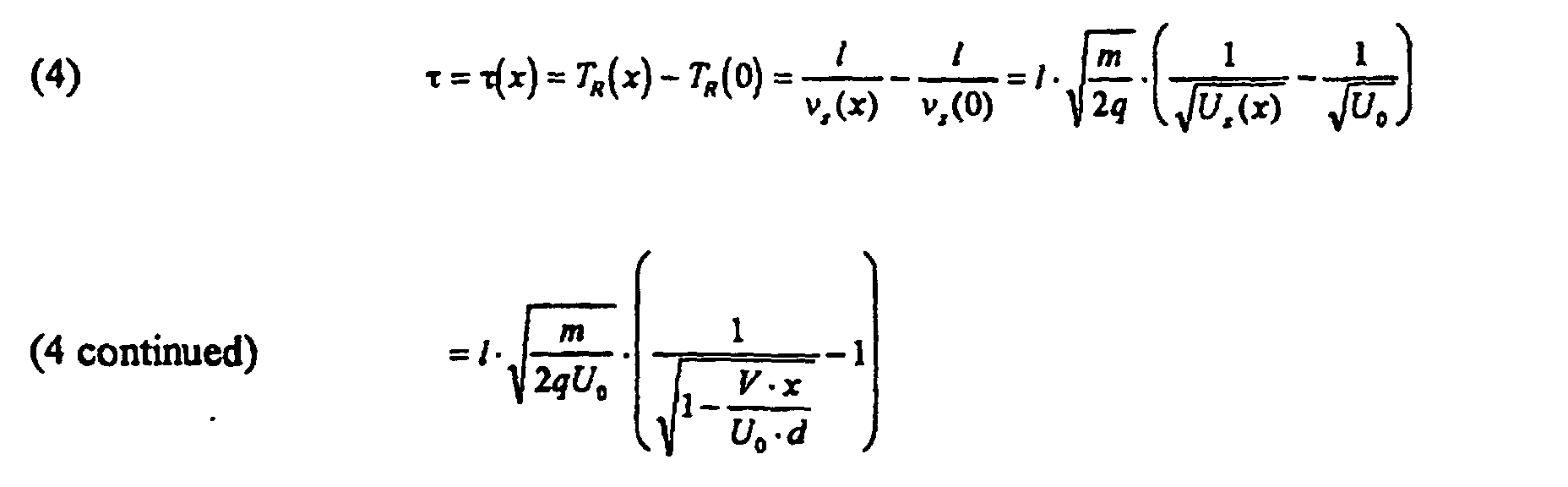
- Here, qU z, and v z are the ion kinetic energy and velocity in the z-direction inside the deflector, T R (x) is the residence time as a function of the entry coordinate x. Vx/U 0 d is small compared to 1 and to first order, τ1, the residence time difference, is given as a function of entry coordinate x by the relation:
- This difference in residence time inside the deflector results in a difference in arrival time with respect to the reference trajectory at any x-y plane at z=z f after the deflector. To evaluate the effect in the deflected beam the transition is made to the primed coordinate system. With the approximations α(x) = α0 i.e. x'(x)=x, and v z (x)=v 0=v z (U 0 ) the difference in the time of arrival is transformed into a spatial shift ζ1 of isochronous points in negative z'-direction.
- The first order the time shift τ1 is a linear function of x or x'. In space the isochronous surface ζ1 (x') is a plane tilted by an angle β with respect to the x'-y' (parallel to the x-y) plane (Fig. 2):
- Inserting (5) and (6) into Equation (7) and comparing with the equation for the deflection angle α0 (Equ. 2) reveals that:
- Equation (8) contains the primary discovery underlying the invention: A package of ions 21 that is isochronous in the x-y plane entering an electrostatic deflector along the z-axis and that is deflected by a certain small angle in the x-z plane is tilted in space with respect to the x-y plane by that same angle but in the opposite sense of rotation (Fig. 3a).
- Symmetry considerations show that a beam entering the deflector under an angle and leaving it along the axis undergoes the same tilting of the isochronous surface (Fig. 3b). In general any deflection of monoenergetic ion packages is accompanied by a tilting of the isochronous surface in the plane of deflection by the deflection angle and in the direction opposite to the direction of deflection. The result can in principle be applied to monoenergetic ion packages independent of the initial shape of the isochronous surface prior to deflection, as any additional distortion is preserved. Hence, multiple deflections can be superimposed, leading to a compound angle inclination of the isochronous surface.
- The mass resolution of a time-of-flight spectrometer is defined as
R=M/ΔM=T/2ΔT=L eq/2w, where M is the ion mass to charge ratio, ΔM the full width at half maximum (FWHM) of the corresponding monoisotopic mass peak, T the mean total flight time of these ions, ΔT the arrival time distribution (FWHM), L eq=T/v 0 the equivalent length of the flight path, and w the apparent width of the ion package upon arrival at the detector surface. - In a conventional TOF-MS the detector surface is mounted perpendicular to the axis of the instrument, i.e. lies in the x'-y' plane. Let w 0 be the width of the undeflected package in z'-direction and b is its width in x-direction determined either by beam limiting apertures or by the open width of the detector itself. Then, the apparent width of the package as it is seen by the detector surface is;
- Depending on the magnitudes of both b and α0 the mass resolution can be considerably diminished. As an example, for a deflection angle of 3 degrees, α0=0.0524 rad, and for typical instrument parameters w 0=0.5mm, b=20 mm, the mass resolution R=Leq /2w achieved would be only one third of the optimum value R 0=L eq/2w 0.
- More generally, with the isochronous ion surface inclined by an angle α and the detector surface inclined by an angle γ with respect to the x'-y' plane the apparent broadening of the ion package w 1 is given by the relation;
- Its contribution to the apparent width w (Equ. 9) vanishes if the two surfaces become aligned, i.e. α - γ = 0. Only then, the package width w that is seen by the detector surface is minimized and equal to w 0.
- The invention therefore states, that, in order to achieve the optimum mass resolution in a linear TOF-MS instrument that uses electrostatic deflectors, the detector surface has to be tilted with respect to the instrument axis in the plane of deflection by an angle equal to the angle of deflection but in the opposite sense of rotation.
- Misalignment between the isochronous ion package surface and the detector surface may also be caused by mechanical tolerances of the vacuum chambers or mounting fixtures, by the bending of chambers or flanges when under the force of outside atmospheric pressure or by other mechanical distortions. It is known in the field of TOF-MS that in order to correct the alignment of the two planes and optimize the performance of a TOF-MS instrument, adjustable detector mounts may be used. It is the new feature of this invention to relate the bias angle of the detector surface directly to the angle of deflection in an instrument that employs electrostatic deflectors.
- A linear TOF-MS is shown schematically in FIG. 4, comprising an ion accelerator with two stages 26 and 27, a drift space 28, and an ion detector 40 with detector surface 34 . The first stage accelerator 26 is formed by repeller electrodes 21 and 22 and the second stage accelerator 27 is formed by the electrodes 22 and 23. These electrodes are essentially flat and mounted parallel to each other and perpendicular to the instrument axis 24. Central openings in electrodes 22 and 23 are covered with meshes 29 and 30 to assure homogenous electric fields in spaces 26 and 27 when electrical potentials are applied to electrodes 21, 22 and 23. It is taught in U.S. Patent No. 2,685,035 (Wiley) and in Wiley et al., that if suitable electric potentials are applied to electrodes 21, 22, 23, a spatial distribution of ions 32 in space 26 with axial width w is expelled from that space and accelerated towards the detector 40 in such a way that the longitudinal distribution in flight direction is compressed to a thin sheet of ions 33 with width w' at the location of the detector 40. This effect is called space focusing or longitudinal focusing.
- Other variants of a linear TOF-MS may comprise additional electrodes, shields, apertures, etc. to suffice for specific needs.
- In one aspect of the invention, which is shown as preferred embodiment in Fig. 4, a continuous beam of ions 41 is at first generated externally to the actual TOF-MS by means of an ion source 10 and accelerating, focusing, and steering electrodes, which comprise an ion transfer system 20. This transfer system may guide the ions through one or more stages of differential pumping and may include means to effectively assimilate the motion of all ions in said beam, preferentially in a high pressure radio-frequency-ion-guide.
- When exiting from the transfer system 20 said ions 41 shall have a mean kinetic energy qU i, where q is the ion charge and U i is a total accelerating electrical potential difference. This initial beam of ions is directed into the gap 26 between the first two electrodes 21 and 22 of the ion accelerator of the linear TOF-MS. It was found to be advantageous (O'Halloran et al.), if the injection is done in such a way that the direction of motion of the initial ion beam 41 is parallel to the accelerator electrodes 21 and 22, hence orthogonal to the instrument axis 24.
- Ions are admitted into the space between electrodes 21 and 22, while those are held at a common electrical potential equal to the electrical potential of the last electrode used to form the initial ion beam, which in turn is preferentially held at ground potential.
- Then, electrical potentials are applied to one or both of said accelerator electrodes 21 and 22 by means of external power supplies and suitable switches. This generates an electric field between these electrodes, which accelerates the ions in space 26. The direction of this accelerating field is orthogonal to the direction of the initial ion beam 41 and is established in such a way that the ions in that space begin to move towards the ion detector 40. At the same time, this field effectively blocks ions of the initial beam from entering into said space.
- In one variant of the preferred embodiment, first stage accelerator 26 may be effectively divided by an additional electrode, the purpose of that electrode being to shield the space where the ions from the initial beam enter the accelerator from the electrical field which penetrates into space 26 from space 27 through the mesh 29. In another variant, additional electrodes held at electrical potentials intermediate to the potentials applied to either electrodes 21 and 22 or 22 and 23, and proportional to their distance from those electrodes, may be used to extend the length of each accelerator stage.
- After the ions have left the accelerator region 26, the electrical potentials applied to the accelerator electrodes 21 and 22 can be reset to their original values, so that new ions from the initial beam 41 can enter into the space between them and a new cycle may begin.
- After passing through the accelerating stages 26 and 27 of the TOF-MS, the ions reach the field free drift space 28. Due to the initial perpendicular motion, the drift direction is oblique to the axis of the accelerator fields and the instrument axis 24. The magnitude of the obliqueness depends only the various energies of the ions when they enter the region 26 and the field free drift region 28.
- Let qU i be the kinetic energy of the ions orthogonal to the axis 24 of the TOF-MS instrument and U 0 be the a total electrical potential difference that accelerates the ions towards the detector 40. Without steering, the angle of the ion trajectories with respect to the axis of the instrument in the field free drift region 28 is given by the ratio of the velocities:
- With typical parameters the drift angle is of the order of several degrees.
- In order to steer the ions in a direction which is parallel to the instrument axis, an electrostatic deflector with plate electrodes 11 and 12 and entrance and exit apertures 14 is employed in the preferred embodiment. The gap between the plates 11 and 12 is chosen but not restricted to be at least twice as wide as the width of the ion beam, and the length of the plates is chosen to be at least twice as long as the gap. The width of the plates is chosen accordingly to the width of the ion beam in that direction, but at least 1.5 times the width of the gap.
- In the preferred embodiment of Fig. 4, the angle of deflection is made equal but opposite to the drift angle, α0 = - by adjusting the electrical potential difference between the deflector plates 11 and 12. As a result, the ions will drift parallel to the instrument axis 24 when leaving the deflector and reach the ion detector 40 at the end of the drift space 28.
- As a further result of the deflection, as it is taught by the invention, the isochronous surface of an ion packet is tilted. This is shown in FIG. 3B and is indicated in FIG. 4 by isochronous surfaces s1 and s2. Hence, according to the invention, it is required that the ion detector surface 34 is tilted with respect to a plane perpendicular to the instrument axis 24, the tilt angle lying in the plane of deflection and being equal to the angle of deflection but in the opposite sense of rotation. From Equation (11) the initial drift angle can be calculated. Hence the required deflection angle is known, as well as the mounting angle of the detector surface and the voltage required to achieve such a deflection for a given deflector geometry.
- In order to accomplish the tilt of the detector surface 34, in the preferred embodiment, the alignment of said detector surface is preset by means of an angular spacer or fixture 35. In addition, the mounting of the detector is made adjustable by means of one or two adjustors 36, adjusting the tilting in the plane of deflection, and the inclination in the perpendicular plane. Preferentially, the adjusters 36 are made in such a way as to allow one to align the surface of the detector while operating the TOF-MS.
- In another variant of the preferred embodiment, the predetermined tilt angle is preset by means of the adjustor or adjusters 36 according to the relations which specify the tilt angle of the isochronous surface of the ion packages.
- The V-shaped geometry of a Reflector-TOF-MS is schematically shown in Fig. 5, the embodiment comprising a single stage accelerator formed by electrodes 51 and 52, a deflector 53, an ion reflector 54 with homogeneous fields, the reflector having one or more stages, and a detector with detector surface 55.
- According to the invention, it is now known that the isochronous surface is tilted by the angle of deflection which is indicated in the FIG. 5 by isochronous surfaces s1, and s2. By following the trajectories 56 and 57 from surfaces s2 to s3 through the reflection of the ion package it becomes evident that the angle of inclination with respect to the plane normal to the reflector axis 58 changes its sign.
- Hence, it follows as essential part of the invention in this preferred embodiment, that the detector surface 55 must be inclined with respect to the instrument axis 24 in the plane of deflection, by the angle of deflection and in the direction of rotation of the deflection.
- As before, this angle may be preset by angular spacers, or preset by adjusters, and may be adjustable around that preset value. Furthermore, by means of multiple, preferentially mutually orthogonal deflectors, a multiple deflection may be facilitated, which, according to the invention, will require a compound angle of the detector surface.
- It was proven that it is unfavorable for the resolution of a Reflector -TOF-MS, if the surface of the in-going and out-going ion package is not aligned parallel with the equipotential or electrode surface of the ion reflector (Karataev et al.).
- Therefore, it is advantageous to employ a setup according to the embodiment of the invention which shown schematically in FIG. 6. It includes the same accelerator, deflector, and reflector as FIG. 5, the deflection angle being α0. In this variant, the reflector axis 59 is inclined with respect to the instrument axis 24, the inclination being in the plane of deflection, and by the angle of deflection.
- In this way, the reflector surface 61 becomes parallel with the isochronous surface s2 of the ion packages, which themselves are tilted due to the deflection by the electrostatic deflector 53. After reflection, the isochronous surface s3 remains parallel to the reflector surface 61, indicated by parallel planes p1, p2, p3, and p4.
- To minimize the width of the ion package which is seen by the detector surface 65, it is furthermore part of this embodiment of the invention, that the detector surface 65 is mounted parallel to the reflector surface 61, by the means as they were already described above.
- Taylor expansion of Equation (1) to second order in the small quantity Vx/U 0 d leads to the equation:where τ1 is the first order shift in time as calculated above (Equ. 4) and τ2 is the second order shift; τ2 gives only positive contributions; ions with x 0 arrive later than it is expected from the first order approximation. In space, the isochronous surface is curved:

- With the beam density being constant in the x-y plane, the second order contribution w 2 to the apparent width is found to be at the most:
- For small detectors (i.e. small b) w 2 is small. With big area detectors, however, w 2 limits the mass resolution of a TOF instrument. In this case, the inverse dependency of w 2 from the plate length l indicates that it is advantageous to utilize rather long deflectors.
- Due to action of the perpendicular field inside the deflectors, ions do not leave at the same x-position as they enter but at a position slightly shifted in the direction of the deflection by the small quantity s=s(x) as can be seen in Fig. 1A. Upon leaving the deflectors they are therefore not regaining the initial energy U 0 but the energy U out that is slightly smaller than U 0.

- As s=s(x) depends on the entry position, this shift introduces a distribution of axial energies. As a result, the ions travel with different velocities and the arrival time distribution at the detector (i.e. the longitudinal focus plane) at a distance L from the deflector exit will be affected. It can be shown that the additional shifts of isochronous points are given by the relation:
- This is only of third order in α0 but depends in first order on L/l suggesting again that rather long deflectors should be used whenever a long flight tube is required. The effect as approximated is also linear in the coordinate x' and therefore leads to a small additional tilt of the isochronous surface. Its impact upon mass resolution can in principle be made to vanish in the same way as the first order effect discussed above as long as the total tilt angle is small.
- So far, only monoenergetic ion beams or ion packages with initial kinetic energy qU=qU 0 in z-direction were considered. A distribution of energies qU= q(1+δ)U 0 around qU 0 with| δ|<<1, δ=(U-U 0)/U 0 will result in a distribution of deflection angles around the angle α0. For small angles, one finds for the angular dispersion from Equation (2):
- In TOF-MS, by means of accelerator configurations like the Wiley/McLaren two stage TOF-accelerator, ions have different energies due to different starting points in the accelerator, but are brought to a longitudinal focus at a plane z=z f. At this plane of interest, at a distance L from the deflector an ion with energy U=U 0 arrives at point X (FIG. 7), whereas an ion with energy U=(1+δ)U 0 will arrive at a different point X' in the same plane z=z f. Ions with energy U 0 are deflected by an angle α0 and form the isochronous plane P inclined by the angle α0 according to the first order result. Ions with energy U=(1+δ)U 0 are deflected by α0+∂α and form a plane P' separated from plane P; note that ∂α is negative when δ is positive; also, P' would be inclined by the angle α0+∂α ≈α0 as is obvious from Equations (1), (2) and (8). The angular dispersion causes a broadening of the ion package in z'-direction to the width w 4. With the total relative energy given by: ((U max-U min )/U 0 )=
δ it is found that - This broadening is of second order in the angle α0 and of first order in the relative energy spread
δ , which is also a small quantity. However, as L increases, the effect will limit the achievable mass resolution. - The effect of an energy spread of the orthogonally injected beam 41 upon the arrival time at the location of the time focus z=zf can be evaluated as follows. First, assume all ions experience the same deflection α0 and they all travel with energy qU 0 in z direction (see FIG. 8). The higher orders in residence time and final energy were already considered separately above. The central ion trajectory with qU i =qU i0 will start at the point X 0 (x 0, 0, 0) and arrive at the point F=(0,0,z f ). Any ion with qU i1<qU i0 will initially travel under the angle α1<α0 and will leave the deflector at an angle α1 - α0<0. In order to arrive at F, this ion would have to start at a different location X 1 (x 1 ,0,0) with x 1>x 0. Inside the deflector this ion follows a trajectory that is more in the "slower" section. Similarly, an ion with initial orthogonal energy qU i2>qU i0 will travel through the deflector in the "faster" section.
- Given the distance L and the difference in exit angle αi - α0 the coordinate x of the trajectory inside is found; then, by using the first order result for the residence time, the arrival time difference is readily evaluated. Consider the inverted problem: Trajectories leave point F with U z =U 0 towards the deflector under an angle γ with respect to the symmetry plane (z-y plane). One finds for γ:
- The orthogonal injection energy can be written as:
- Then, inserting (21) into (20)

- Under the assumption of small angles the deflector entry position in the inverted problem is now found easily:

- For the difference of residence times inside the deflector between an ion that enters at x 0 compared to the reference ion with x=0 one has from the first order relation:v 0=vz(U 0 ) is the velocity of an ion of energy qU 0 in the z-direction. Collecting terms, the total difference in flight time between an ion with orthogonal energy qU i and the reference trajectory with U i =U i0 is found as a function of the parameter ε:


- With |ε|<<1 this can be approximated by expansion of the square root:

- The total relative energy spread is given as ((U i,max - U i,min )/U i,0 ) = εmax - εmin =
ε . Consequently, one has for the total flight time distribution from the orthogonal injection input line to the point F: - This is evidently equivalent with the arrival time distribution at point F for ions starting at the same time along the input line. This spread of arrival times at the point F corresponds to a broadening of the ion package:
- The effect is found to be of second order in α0 and small only if the product L·
ε is much smaller than 1/α0. It follows that in order to achieve best mass resolution results it is necessary to control the relative distribution of orthogonal injection energies. Hence, it is advantageous, according to the invention, to include means into the ion transfer system between the ion source 10 and the TOF-MS (FIG. 4), that effectively normalizes or homogenizes the relative motions of the ions. - Electrostatic lenses are used to focus the ions on the detector of the TOF-MS in order to improve the sensitivity of the instrument. In a focused beam, a trajectory that starts with the coordinate x will be at a distance x'=λ•x with λ<1 from the reference trajectory at the plane z=z f. If the focusing lens does not introduce any additional time shifts then ζ1 will be unchanged. Hence, the angle of inclination of the isochronous plane will be increased:
- Focusing of the beam to half the original size in x-direction will double the tangent of the inclination angle of the isochronous surface. For stronger focusing, i. e. λ<<1, β' becomes impractically large. Obviously this strong effect limits the use of deflectors in combination with focusing elements. For moderate λ, however, the correction by tilting the detector surface at the appropriate angle can be applied.
- The following references are referred to above:
U.S. Patent Documents:
2,685,035 July 27, 1954 Wiley
4,072,862 Feb. 7, 1978 Mamyrin et al.
Foreign Patent Documents:
198,034 Soviet Union (Mamyrin Russian Patent, filed 1966) - Other Publications:
- W. C. Wiley, I. H. McLaren, Rev. Sci. Inst. 26, 1150 (1955)
- G. J. O'Halloran, R A. Fluegge, J. F. Betts, W. L. Everett, Report No. ASD-TDR 62-644, Prepared under Contract AF 33(616)-8374 by The Bendix Corporation Research Laboratories Division, Southfield, Michigan (1964)
- J. H. J. Dawson, M. Guilhaus, Rapid Commun. Mass Spectrom. 3, 155 (1989)
- A. F. Dodonov, I. V. Chernushevich, V. V. Laiko, 12th Int. Mass Spectr. Conference, Amsterdam (1991);
- O. A. Migorodskaya, A. A. Shevchenko, I. V. Chernushevich, A. F. Dodonov, A. I. Miroshnikov, Anal. Chem. 66, 99 (1994)
- A. N. Verentchikov, W. Ens, K. G. Standing, Anal. Chem. 66, 126 (1994)
- R F. Herzog, Z. Phys. 89 (1934), 97 (1935); Z. Naturforsch 8a, 191 (1953), 10a, 887 (1955)
- V. I. Karataev, B. A. Mamyrin, D. V. Shmikk, Sov. Phys. Tech. Phys. 16, 1177 (1972);
- B. A. Mamyrin, V. I. Karataev, D. V. Shmikk, V. A. Zagulin, Sov. Phys. JETP 37, 45 (1973)
-
Claims (12)
- An apparatus for separation of ionic species using a time-of-flight mass analyzer, comprising:an instrument axis (24);an ion beam steering lens (11, 12) having a homogeneous electrostatic field which is directed predominantly sideways to said instrument axis (24), said steering lens (11, 12) deflecting ion packets passing through said steering lens (11, 12) such that said ion packets are deflected by an angle of deflection (α0) and essentially form a plane (S2) tilted with respect to a plane perpendicular to said axis (24) by an angle equal to said angle of deflection (α0) but in the opposite sense of rotation; andan ion detector (40) placed at the end of a flight tube analyzer region for detection of said ion packets, said detector having a detection surface (34) wherein said detector surface (34) is tilted with respect to a plane perpendicular to said axis (24), by an angle equal to said angle of deflection (α0) of said ion packets but in the opposite sense of rotation such that said detector surface (34) is parallel to said plane (S2) of said ion packets.
- An apparatus for separation of ionic species using a reflectron-time-of-flight mass analyzer comprising:an instrument axis (24);an ion beam steering lens (53) having a homogeneous electrostatic field, which is directed predominantly sideways said instrument axis (24), said steering lens (53) deflecting ion packets passing through said steering lens (53) such that said packets are deflected by an angle of deflection (α0) and essentially form a plane (S2) tilted with respect to a plane perpendicular to said axis by an angle equal to said angle of deflection (α0) but in the opposite sense of rotation;an ion reflector (54) having a homogeneous electrostatic field, said ion reflector having a reflector axis (58) which is parallel to said instrument axis, and;an ion detector with detector surface (55) placed after the reflector (54) at the end of a flight tube analyzer region where said detector surface (55) is tilted with respect to the plane perpendicular to said axis of the reflector (54) by an angle equal to the angle of deflection (α0) and in the direction of deflection, such that said detector surface (55) is parallel to said plane of ion packets (S3) arriving at said detector surface (55).
- An apparatus for separation of ionic species using a reflectron-time-of-flight mass analyzer comprising:an instrument axis (24);an ion beam steering lens (53) having a homogeneous electrostatic field, which is directed predominantly sideways to said instrument axis (24), said steering lens (53) deflecting ion packets travelling through said steering lens (53) such that said packets are deflected by an angle of deflection (α0) and essentially form a plane (s2) tilted with respect to a plane perpendicular to said axis by an angle equal to said angle of deflection (α0) but in the opposite sense of rotation;an ion reflector (54) having a homogeneous electrostatic field having a reflector surface (61) which is tilted with respect to a plane perpendicular to said instrument axis by an angle equal to said angle of deflection (α0) of said ion packets but in the opposite sense of rotation;an ion detector with detector surface (65) placed after the reflector (54) at the end of a flight tube analyzer region where said detector surface (65) is parallel to the reflector surface (61) such that said detector surface (65) is parallel to said plane of ion packets (S3) arriving at said detector surface (65).
- An apparatus according to any of claims 1 to 3, wherein said steering lens (11, 12, 53) has an entry and an exit aperture containing plates to reduce the fringing fields felt by said ion packets;
- An apparatus according to any of claims 1 to 3, wherein said analyzer contains multiple homogeneous electrostatic deflection fields, the direction of those fields being different or identical such that the multiple deflections are superimposed leading to a compound angle of deflection, said surface (34) of the detector (40) being tilted by said compound angle of deflection.
- An apparatus according to any of claims 1 to 3, wherein the homogeneous deflection fields are generated by means of a pair or pairs of parallel plate electrodes (11, 12).
- An apparatus according to any of claims 1 to 3, wherein said homogeneous deflection fields are generated by means of other suitable sets of electrodes.
- An apparatus according to any of claims 1 to 5, further comprising a tilting mechanism (36) to adjust and achieve the best angle for said detector surface (34) matching said angle of deflection (α0) of said ion packets, said tilting mechanism (36) being hermetically sealed within a vacuum enclosure, and having a means for adjustment of said tilting mechanism located outside said vacuum enclosure.
- An apparatus according to any of claims 1 to 5, wherein the inclination of the detector surface (34) is biased according to the angle of deflection, but is adjustable around that angle.
- An apparatus according to any of claims 1 to 3, wherein the ions are generated externally to said analyzer and injected by means of electrical acceleration into said analyzer orthogonal to the direction of the analyzer's first acceleration field.
- An apparatus according to claim 10, wherein the relative motion of the ions prior to injection is homogenized, preferentially by means of a high pressure multipole radio-frequency ion guide.
- An apparatus according to claim 5, comprising two mutually perpendicular deflecting fields to deflect said ion packets.
Applications Claiming Priority (5)
| Application Number | Priority Date | Filing Date | Title |
|---|---|---|---|
| US08/694,878 US5654544A (en) | 1995-08-10 | 1996-08-09 | Mass resolution by angular alignment of the ion detector conversion surface in time-of-flight mass spectrometers with electrostatic steering deflectors |
| US694878 | 1996-08-09 | ||
| US08/880,060 US5847385A (en) | 1996-08-09 | 1997-06-20 | Mass resolution by angular alignment of the ion detector conversion surface in time-of-flight mass spectrometers with electrostatic steering deflectors |
| US880060 | 1997-06-20 | ||
| PCT/US1997/014195 WO1998007179A1 (en) | 1996-08-09 | 1997-08-11 | An angular alignement of the ion detector surface in time-of-flight mass spectrometers |
Publications (3)
| Publication Number | Publication Date |
|---|---|
| EP0917727A1 EP0917727A1 (en) | 1999-05-26 |
| EP0917727A4 EP0917727A4 (en) | 2000-07-12 |
| EP0917727B1 true EP0917727B1 (en) | 2005-06-08 |
Family
ID=27105457
Family Applications (1)
| Application Number | Title | Priority Date | Filing Date |
|---|---|---|---|
| EP97936486A Expired - Lifetime EP0917727B1 (en) | 1996-08-09 | 1997-08-11 | An angular alignement of the ion detector surface in time-of-flight mass spectrometers |
Country Status (6)
| Country | Link |
|---|---|
| US (1) | US5847385A (en) |
| EP (1) | EP0917727B1 (en) |
| JP (1) | JP2001523378A (en) |
| AU (1) | AU3914397A (en) |
| DE (1) | DE69733477T2 (en) |
| WO (2) | WO1998007176A1 (en) |
Families Citing this family (43)
| Publication number | Priority date | Publication date | Assignee | Title |
|---|---|---|---|---|
| US6518569B1 (en) * | 1999-06-11 | 2003-02-11 | Science & Technology Corporation @ Unm | Ion mirror |
| US6369384B1 (en) | 1999-06-23 | 2002-04-09 | Agilent Technologies, Inc. | Time-of-flight mass spectrometer with post-deflector filter assembly |
| US6365893B1 (en) | 1999-11-23 | 2002-04-02 | Agilent Technologies, Inc. | Internal calibration of time to mass conversion in time-of-flight mass spectrometry |
| JP2005503178A (en) * | 2000-01-25 | 2005-02-03 | ボストン サイエンティフィック リミテッド | Manufacturing medical devices by vapor deposition |
| US7084395B2 (en) * | 2001-05-25 | 2006-08-01 | Ionwerks, Inc. | Time-of-flight mass spectrometer for monitoring of fast processes |
| US20040124351A1 (en) * | 2001-09-25 | 2004-07-01 | Pineda Fernando J | Method for calibration of time-of-flight mass spectrometers |
| DE10156604A1 (en) * | 2001-11-17 | 2003-05-28 | Bruker Daltonik Gmbh | Spatial angle focusing reflector for flight time mass spectrometer has field between last annular aperture and terminating aperture made weaker than between preceding reflector apertures |
| DE10162267B4 (en) * | 2001-12-18 | 2007-05-31 | Bruker Daltonik Gmbh | Reflector for time-of-flight mass spectrometers with orthogonal ion injection |
| GB0200469D0 (en) * | 2002-01-10 | 2002-02-27 | Amersham Biosciences Ab | Adaptive mounting |
| WO2006102430A2 (en) | 2005-03-22 | 2006-09-28 | Leco Corporation | Multi-reflecting time-of-flight mass spectrometer with isochronous curved ion interface |
| WO2007044696A1 (en) * | 2005-10-11 | 2007-04-19 | Leco Corporation | Multi-reflecting time-of-flight mass spectrometer with orthogonal acceleration |
| US7709789B2 (en) * | 2008-05-29 | 2010-05-04 | Virgin Instruments Corporation | TOF mass spectrometry with correction for trajectory error |
| CN102150219B (en) * | 2008-07-28 | 2015-01-28 | 莱克公司 | Method and apparatus for ion manipulation using mesh in a radio frequency field |
| US7932491B2 (en) * | 2009-02-04 | 2011-04-26 | Virgin Instruments Corporation | Quantitative measurement of isotope ratios by time-of-flight mass spectrometry |
| US20100301202A1 (en) * | 2009-05-29 | 2010-12-02 | Virgin Instruments Corporation | Tandem TOF Mass Spectrometer With High Resolution Precursor Selection And Multiplexed MS-MS |
| US8847155B2 (en) | 2009-08-27 | 2014-09-30 | Virgin Instruments Corporation | Tandem time-of-flight mass spectrometry with simultaneous space and velocity focusing |
| US8461521B2 (en) | 2010-12-14 | 2013-06-11 | Virgin Instruments Corporation | Linear time-of-flight mass spectrometry with simultaneous space and velocity focusing |
| US20110049350A1 (en) * | 2009-08-27 | 2011-03-03 | Virgin Instruments Corporation | Tandem TOF Mass Spectrometer With Pulsed Accelerator To Reduce Velocity Spread |
| US8674292B2 (en) | 2010-12-14 | 2014-03-18 | Virgin Instruments Corporation | Reflector time-of-flight mass spectrometry with simultaneous space and velocity focusing |
| US8399828B2 (en) * | 2009-12-31 | 2013-03-19 | Virgin Instruments Corporation | Merged ion beam tandem TOF-TOF mass spectrometer |
| US8698107B2 (en) * | 2011-01-10 | 2014-04-15 | Varian Semiconductor Equipment Associates, Inc. | Technique and apparatus for monitoring ion mass, energy, and angle in processing systems |
| GB201108082D0 (en) * | 2011-05-16 | 2011-06-29 | Micromass Ltd | Segmented planar calibration for correction of errors in time of flight mass spectrometers |
| JP5885474B2 (en) * | 2011-11-17 | 2016-03-15 | キヤノン株式会社 | Mass distribution analysis method and mass distribution analyzer |
| US9123521B2 (en) * | 2012-04-26 | 2015-09-01 | Leco Corporation | Electron impact ion source with fast response |
| US8735810B1 (en) | 2013-03-15 | 2014-05-27 | Virgin Instruments Corporation | Time-of-flight mass spectrometer with ion source and ion detector electrically connected |
| WO2015026727A1 (en) | 2013-08-19 | 2015-02-26 | Virgin Instruments Corporation | Ion optical system for maldi-tof mass spectrometer |
| US9536723B1 (en) * | 2015-02-06 | 2017-01-03 | Agilent Technologies, Inc. | Thin field terminator for linear quadrupole ion guides, and related systems and methods |
| GB2543036A (en) * | 2015-10-01 | 2017-04-12 | Shimadzu Corp | Time of flight mass spectrometer |
| GB2567794B (en) | 2017-05-05 | 2023-03-08 | Micromass Ltd | Multi-reflecting time-of-flight mass spectrometers |
| GB2563571B (en) | 2017-05-26 | 2023-05-24 | Micromass Ltd | Time of flight mass analyser with spatial focussing |
| US11817303B2 (en) * | 2017-08-06 | 2023-11-14 | Micromass Uk Limited | Accelerator for multi-pass mass spectrometers |
| EP3662502A1 (en) | 2017-08-06 | 2020-06-10 | Micromass UK Limited | Printed circuit ion mirror with compensation |
| WO2019030472A1 (en) | 2017-08-06 | 2019-02-14 | Anatoly Verenchikov | Ion mirror for multi-reflecting mass spectrometers |
| JP6808669B2 (en) | 2018-03-14 | 2021-01-06 | 日本電子株式会社 | Mass spectrometer |
| GB201806507D0 (en) | 2018-04-20 | 2018-06-06 | Verenchikov Anatoly | Gridless ion mirrors with smooth fields |
| GB201807626D0 (en) | 2018-05-10 | 2018-06-27 | Micromass Ltd | Multi-reflecting time of flight mass analyser |
| GB201807605D0 (en) | 2018-05-10 | 2018-06-27 | Micromass Ltd | Multi-reflecting time of flight mass analyser |
| JP6874906B2 (en) * | 2018-05-16 | 2021-05-19 | 株式会社島津製作所 | Time-of-flight mass spectrometer |
| GB201808459D0 (en) * | 2018-05-23 | 2018-07-11 | Thermo Fisher Scient Bremen Gmbh | Ion front tilt correction for time of flight(tof) mass spectrometer |
| GB201808530D0 (en) | 2018-05-24 | 2018-07-11 | Verenchikov Anatoly | TOF MS detection system with improved dynamic range |
| GB201810573D0 (en) | 2018-06-28 | 2018-08-15 | Verenchikov Anatoly | Multi-pass mass spectrometer with improved duty cycle |
| GB2576745B (en) * | 2018-08-30 | 2022-11-02 | Brian Hoyes John | Pulsed accelerator for time of flight mass spectrometers |
| GB201903779D0 (en) | 2019-03-20 | 2019-05-01 | Micromass Ltd | Multiplexed time of flight mass spectrometer |
Family Cites Families (7)
| Publication number | Priority date | Publication date | Assignee | Title |
|---|---|---|---|---|
| US2642535A (en) * | 1946-10-18 | 1953-06-16 | Rca Corp | Mass spectrometer |
| US2938116A (en) * | 1956-04-02 | 1960-05-24 | Vard Products Inc | Molecular mass spectrometer |
| FR2514905A1 (en) * | 1981-10-21 | 1983-04-22 | Commissariat Energie Atomique | DEVICE FOR MEASURING IONIC CURRENT PRODUCED BY ION BEAM |
| DE3842044A1 (en) * | 1988-12-14 | 1990-06-21 | Forschungszentrum Juelich Gmbh | FLIGHT TIME (MASS) SPECTROMETER WITH HIGH RESOLUTION AND TRANSMISSION |
| US5160840A (en) * | 1991-10-25 | 1992-11-03 | Vestal Marvin L | Time-of-flight analyzer and method |
| US5689111A (en) * | 1995-08-10 | 1997-11-18 | Analytica Of Branford, Inc. | Ion storage time-of-flight mass spectrometer |
| US5654544A (en) * | 1995-08-10 | 1997-08-05 | Analytica Of Branford | Mass resolution by angular alignment of the ion detector conversion surface in time-of-flight mass spectrometers with electrostatic steering deflectors |
-
1997
- 1997-06-20 US US08/880,060 patent/US5847385A/en not_active Expired - Lifetime
- 1997-08-04 WO PCT/US1997/013625 patent/WO1998007176A1/en not_active Ceased
- 1997-08-11 EP EP97936486A patent/EP0917727B1/en not_active Expired - Lifetime
- 1997-08-11 WO PCT/US1997/014195 patent/WO1998007179A1/en not_active Ceased
- 1997-08-11 AU AU39143/97A patent/AU3914397A/en not_active Abandoned
- 1997-08-11 DE DE69733477T patent/DE69733477T2/en not_active Expired - Fee Related
- 1997-08-11 JP JP50997098A patent/JP2001523378A/en active Pending
Also Published As
| Publication number | Publication date |
|---|---|
| US5847385A (en) | 1998-12-08 |
| WO1998007179A1 (en) | 1998-02-19 |
| DE69733477T2 (en) | 2006-03-23 |
| WO1998007176A1 (en) | 1998-02-19 |
| EP0917727A4 (en) | 2000-07-12 |
| JP2001523378A (en) | 2001-11-20 |
| EP0917727A1 (en) | 1999-05-26 |
| AU3914397A (en) | 1998-03-06 |
| DE69733477D1 (en) | 2005-07-14 |
Similar Documents
| Publication | Publication Date | Title |
|---|---|---|
| US5654544A (en) | Mass resolution by angular alignment of the ion detector conversion surface in time-of-flight mass spectrometers with electrostatic steering deflectors | |
| US5847385A (en) | Mass resolution by angular alignment of the ion detector conversion surface in time-of-flight mass spectrometers with electrostatic steering deflectors | |
| US6621073B1 (en) | Time-of-flight mass spectrometer with first and second order longitudinal focusing | |
| US7982184B2 (en) | Multi-reflecting time-of-flight mass analyser and a time-of-flight mass spectrometer including the mass analyser | |
| US8921775B2 (en) | Electrostatic gimbal for correction of errors in time of flight mass spectrometers | |
| US9245728B2 (en) | Mass spectrometer with beam expander | |
| US10741376B2 (en) | Multi-reflecting TOF mass spectrometer | |
| JP5553921B2 (en) | Multiple reflection time-of-flight mass analyzer | |
| US5160840A (en) | Time-of-flight analyzer and method | |
| WO2018033494A1 (en) | Mass analyser having extended flight path | |
| US5077472A (en) | Ion mirror for a time-of-flight mass spectrometer | |
| GB2274197A (en) | Time-of-flight mass spectrometer | |
| US6858839B1 (en) | Ion optics for mass spectrometers | |
| US7372021B2 (en) | Time-of-flight mass spectrometer combining fields non-linear in time and space | |
| CA2262615C (en) | An angular alignement of the ion detector surface in time-of-flight mass spectrometers | |
| US9129790B2 (en) | Orthogonal acceleration TOF with ion guide mode |
Legal Events
| Date | Code | Title | Description |
|---|---|---|---|
| PUAI | Public reference made under article 153(3) epc to a published international application that has entered the european phase |
Free format text: ORIGINAL CODE: 0009012 |
|
| 17P | Request for examination filed |
Effective date: 19990218 |
|
| AK | Designated contracting states |
Kind code of ref document: A1 Designated state(s): CH DE DK FR GB IT LI SE |
|
| A4 | Supplementary search report drawn up and despatched |
Effective date: 20000530 |
|
| AK | Designated contracting states |
Kind code of ref document: A4 Designated state(s): CH DE DK FR GB IT LI SE |
|
| RIC1 | Information provided on ipc code assigned before grant |
Free format text: 7H 01J 49/00 A, 7H 01J 49/40 B |
|
| 17Q | First examination report despatched |
Effective date: 20030128 |
|
| GRAP | Despatch of communication of intention to grant a patent |
Free format text: ORIGINAL CODE: EPIDOSNIGR1 |
|
| GRAS | Grant fee paid |
Free format text: ORIGINAL CODE: EPIDOSNIGR3 |
|
| GRAA | (expected) grant |
Free format text: ORIGINAL CODE: 0009210 |
|
| AK | Designated contracting states |
Kind code of ref document: B1 Designated state(s): CH DE DK FR GB IT LI SE |
|
| PG25 | Lapsed in a contracting state [announced via postgrant information from national office to epo] |
Ref country code: LI Free format text: LAPSE BECAUSE OF FAILURE TO SUBMIT A TRANSLATION OF THE DESCRIPTION OR TO PAY THE FEE WITHIN THE PRESCRIBED TIME-LIMIT Effective date: 20050608 Ref country code: IT Free format text: LAPSE BECAUSE OF FAILURE TO SUBMIT A TRANSLATION OF THE DESCRIPTION OR TO PAY THE FEE WITHIN THE PRE;WARNING: LAPSES OF ITALIAN PATENTS WITH EFFECTIVE DATE BEFORE 2007 MAY HAVE OCCURRED AT ANY TIME BEFORE 2007. THE CORRECT EFFECTIVE DATE MAY BE DIFFERENT FROM THE ONE RECORDED.SCRIBED TIME-LIMIT Effective date: 20050608 Ref country code: CH Free format text: LAPSE BECAUSE OF FAILURE TO SUBMIT A TRANSLATION OF THE DESCRIPTION OR TO PAY THE FEE WITHIN THE PRESCRIBED TIME-LIMIT Effective date: 20050608 |
|
| REG | Reference to a national code |
Ref country code: GB Ref legal event code: FG4D |
|
| REG | Reference to a national code |
Ref country code: CH Ref legal event code: EP |
|
| REF | Corresponds to: |
Ref document number: 69733477 Country of ref document: DE Date of ref document: 20050714 Kind code of ref document: P |
|
| PGFP | Annual fee paid to national office [announced via postgrant information from national office to epo] |
Ref country code: DE Payment date: 20050804 Year of fee payment: 9 |
|
| PGFP | Annual fee paid to national office [announced via postgrant information from national office to epo] |
Ref country code: FR Payment date: 20050809 Year of fee payment: 9 |
|
| PGFP | Annual fee paid to national office [announced via postgrant information from national office to epo] |
Ref country code: GB Payment date: 20050810 Year of fee payment: 9 |
|
| PG25 | Lapsed in a contracting state [announced via postgrant information from national office to epo] |
Ref country code: SE Free format text: LAPSE BECAUSE OF FAILURE TO SUBMIT A TRANSLATION OF THE DESCRIPTION OR TO PAY THE FEE WITHIN THE PRESCRIBED TIME-LIMIT Effective date: 20050908 Ref country code: DK Free format text: LAPSE BECAUSE OF FAILURE TO SUBMIT A TRANSLATION OF THE DESCRIPTION OR TO PAY THE FEE WITHIN THE PRESCRIBED TIME-LIMIT Effective date: 20050908 |
|
| REG | Reference to a national code |
Ref country code: CH Ref legal event code: PL |
|
| ET | Fr: translation filed | ||
| PLBE | No opposition filed within time limit |
Free format text: ORIGINAL CODE: 0009261 |
|
| STAA | Information on the status of an ep patent application or granted ep patent |
Free format text: STATUS: NO OPPOSITION FILED WITHIN TIME LIMIT |
|
| 26N | No opposition filed |
Effective date: 20060309 |
|
| PG25 | Lapsed in a contracting state [announced via postgrant information from national office to epo] |
Ref country code: DE Free format text: LAPSE BECAUSE OF NON-PAYMENT OF DUE FEES Effective date: 20070301 |
|
| GBPC | Gb: european patent ceased through non-payment of renewal fee |
Effective date: 20060811 |
|
| REG | Reference to a national code |
Ref country code: FR Ref legal event code: ST Effective date: 20070430 |
|
| PG25 | Lapsed in a contracting state [announced via postgrant information from national office to epo] |
Ref country code: GB Free format text: LAPSE BECAUSE OF NON-PAYMENT OF DUE FEES Effective date: 20060811 |
|
| PG25 | Lapsed in a contracting state [announced via postgrant information from national office to epo] |
Ref country code: FR Free format text: LAPSE BECAUSE OF NON-PAYMENT OF DUE FEES Effective date: 20060831 |