EP0917509B1 - Ink jet printhead and ink jet printer - Google Patents
Ink jet printhead and ink jet printer Download PDFInfo
- Publication number
- EP0917509B1 EP0917509B1 EP97942160A EP97942160A EP0917509B1 EP 0917509 B1 EP0917509 B1 EP 0917509B1 EP 97942160 A EP97942160 A EP 97942160A EP 97942160 A EP97942160 A EP 97942160A EP 0917509 B1 EP0917509 B1 EP 0917509B1
- Authority
- EP
- European Patent Office
- Prior art keywords
- plate
- actuator
- ink jet
- active
- main face
- Prior art date
- Legal status (The legal status is an assumption and is not a legal conclusion. Google has not performed a legal analysis and makes no representation as to the accuracy of the status listed.)
- Expired - Lifetime
Links
- 239000012528 membrane Substances 0.000 claims description 23
- 239000000463 material Substances 0.000 claims description 10
- 239000000919 ceramic Substances 0.000 claims description 5
- 230000008859 change Effects 0.000 claims description 5
- 239000011149 active material Substances 0.000 claims 1
- PXHVJJICTQNCMI-UHFFFAOYSA-N Nickel Chemical compound [Ni] PXHVJJICTQNCMI-UHFFFAOYSA-N 0.000 description 8
- 239000002184 metal Substances 0.000 description 8
- 229910052751 metal Inorganic materials 0.000 description 8
- 239000004020 conductor Substances 0.000 description 7
- 238000006073 displacement reaction Methods 0.000 description 6
- 239000011888 foil Substances 0.000 description 6
- 238000000034 method Methods 0.000 description 6
- 239000000758 substrate Substances 0.000 description 5
- 229910052759 nickel Inorganic materials 0.000 description 4
- 229910000679 solder Inorganic materials 0.000 description 4
- 229910010293 ceramic material Inorganic materials 0.000 description 3
- 230000000694 effects Effects 0.000 description 3
- 238000005530 etching Methods 0.000 description 3
- 239000011521 glass Substances 0.000 description 3
- 238000004904 shortening Methods 0.000 description 3
- 239000004952 Polyamide Substances 0.000 description 2
- 238000010276 construction Methods 0.000 description 2
- 238000010586 diagram Methods 0.000 description 2
- 230000002708 enhancing effect Effects 0.000 description 2
- PCHJSUWPFVWCPO-UHFFFAOYSA-N gold Chemical compound [Au] PCHJSUWPFVWCPO-UHFFFAOYSA-N 0.000 description 2
- 239000010931 gold Substances 0.000 description 2
- 229910052737 gold Inorganic materials 0.000 description 2
- UGKDIUIOSMUOAW-UHFFFAOYSA-N iron nickel Chemical compound [Fe].[Ni] UGKDIUIOSMUOAW-UHFFFAOYSA-N 0.000 description 2
- 230000004048 modification Effects 0.000 description 2
- 238000012986 modification Methods 0.000 description 2
- 239000004033 plastic Substances 0.000 description 2
- 229920002647 polyamide Polymers 0.000 description 2
- 230000008569 process Effects 0.000 description 2
- 238000009736 wetting Methods 0.000 description 2
- RYGMFSIKBFXOCR-UHFFFAOYSA-N Copper Chemical compound [Cu] RYGMFSIKBFXOCR-UHFFFAOYSA-N 0.000 description 1
- 229910003271 Ni-Fe Inorganic materials 0.000 description 1
- BLRPTPMANUNPDV-UHFFFAOYSA-N Silane Chemical compound [SiH4] BLRPTPMANUNPDV-UHFFFAOYSA-N 0.000 description 1
- 239000004809 Teflon Substances 0.000 description 1
- 229920006362 Teflon® Polymers 0.000 description 1
- 230000002411 adverse Effects 0.000 description 1
- 229910045601 alloy Inorganic materials 0.000 description 1
- 239000000956 alloy Substances 0.000 description 1
- 238000005452 bending Methods 0.000 description 1
- 238000005422 blasting Methods 0.000 description 1
- 239000003086 colorant Substances 0.000 description 1
- 229910052802 copper Inorganic materials 0.000 description 1
- 239000010949 copper Substances 0.000 description 1
- 230000003247 decreasing effect Effects 0.000 description 1
- 238000000151 deposition Methods 0.000 description 1
- 239000007788 liquid Substances 0.000 description 1
- 238000003754 machining Methods 0.000 description 1
- 238000004519 manufacturing process Methods 0.000 description 1
- 239000011159 matrix material Substances 0.000 description 1
- 229920003223 poly(pyromellitimide-1,4-diphenyl ether) Polymers 0.000 description 1
- 239000000843 powder Substances 0.000 description 1
- 229910000077 silane Inorganic materials 0.000 description 1
- 230000007723 transport mechanism Effects 0.000 description 1
Images




Classifications
-
- B—PERFORMING OPERATIONS; TRANSPORTING
- B41—PRINTING; LINING MACHINES; TYPEWRITERS; STAMPS
- B41J—TYPEWRITERS; SELECTIVE PRINTING MECHANISMS, i.e. MECHANISMS PRINTING OTHERWISE THAN FROM A FORME; CORRECTION OF TYPOGRAPHICAL ERRORS
- B41J2/00—Typewriters or selective printing mechanisms characterised by the printing or marking process for which they are designed
- B41J2/005—Typewriters or selective printing mechanisms characterised by the printing or marking process for which they are designed characterised by bringing liquid or particles selectively into contact with a printing material
- B41J2/01—Ink jet
- B41J2/135—Nozzles
- B41J2/14—Structure thereof only for on-demand ink jet heads
- B41J2/14201—Structure of print heads with piezoelectric elements
- B41J2/14274—Structure of print heads with piezoelectric elements of stacked structure type, deformed by compression/extension and disposed on a diaphragm
-
- B—PERFORMING OPERATIONS; TRANSPORTING
- B41—PRINTING; LINING MACHINES; TYPEWRITERS; STAMPS
- B41J—TYPEWRITERS; SELECTIVE PRINTING MECHANISMS, i.e. MECHANISMS PRINTING OTHERWISE THAN FROM A FORME; CORRECTION OF TYPOGRAPHICAL ERRORS
- B41J2/00—Typewriters or selective printing mechanisms characterised by the printing or marking process for which they are designed
- B41J2/005—Typewriters or selective printing mechanisms characterised by the printing or marking process for which they are designed characterised by bringing liquid or particles selectively into contact with a printing material
- B41J2/01—Ink jet
- B41J2/135—Nozzles
- B41J2/14—Structure thereof only for on-demand ink jet heads
- B41J2002/14419—Manifold
-
- B—PERFORMING OPERATIONS; TRANSPORTING
- B41—PRINTING; LINING MACHINES; TYPEWRITERS; STAMPS
- B41J—TYPEWRITERS; SELECTIVE PRINTING MECHANISMS, i.e. MECHANISMS PRINTING OTHERWISE THAN FROM A FORME; CORRECTION OF TYPOGRAPHICAL ERRORS
- B41J2/00—Typewriters or selective printing mechanisms characterised by the printing or marking process for which they are designed
- B41J2/005—Typewriters or selective printing mechanisms characterised by the printing or marking process for which they are designed characterised by bringing liquid or particles selectively into contact with a printing material
- B41J2/01—Ink jet
- B41J2/135—Nozzles
- B41J2/14—Structure thereof only for on-demand ink jet heads
- B41J2002/14491—Electrical connection
Definitions
- the invention relates to an ink jet printhead comprising:
- the actuator plate is a piezoceramic plate.
- the actuator elements are embossed parts of the actuator plate that overly the pressure chambers.
- the actuator elements are provided with film electrodes to which electrical connections have to be made outside the area above the pressure chambers so that the mass of the electrical connections does not affect the resonance frequency of the actuator elements. Consequently, the area of the actuator elements necessarily exceeds the area of the pressure chambers so that the total area of the actuator plate is comparatively large.
- many electrical connections have to be made with great precision which is time-consuming and increases the manufacturing cost of the device.
- the printhead in accordance with the invention is characterized in that between the second main face of the actuator plate and the first main face of the membrane there is provided a support plate comprising first portions and a second portion, said first portions being movable relative to the second portions in the direction of the thickness of the support plate, a first portion being situated between each actuator element and the corresponding pressure chamber; the actuator plate having active regions and inactive regions, the actuator elements being formed by active regions of the actuator plate, adjacent actuator elements being separated from each other over substantially their whole length by slits provided in the actuator plate.
- the first portions of the support plate act as pistons that are driven by the actuator elements.
- the surface area of these pistons may be only slightly smaller than that of the pressure chambers so that sufficient play exists between each piston and the walls of the corresponding pressure chamber to ensure that the piston can move freely.
- the corresponding actuator element may have a smaller area than the piston without the efficiency of the energy transfer being adversely affected.
- the actuator plate is a ceramic multilayer actuator (CMA).
- CMAs ceramic multilayer actuator
- ink jet printheads are known per se, e.g. from EP-A-0 573 055. Some advantages of such devices are that their efficiency is high and that the contacts can be made at an area remote from the active regions.
- the actuator elements are formed as bars that change their length upon application of a suitable voltage. As a result, the thickness of the printhead (the dimension in a direction perpendicular to the main faces of the body) is rather large which is in conflict with the desire to reduce the dimensions of the printhead.
- a preferred embodiment of the printhead in accordance with the invention is characterized in that a top plate is attached to the first main face of the actuator plate, the top plate being provided with slits corresponding to the slits in the actuator plate.
- the actuator elements are conceived to change their dimension in the thickness direction.
- the relevant actuator element is controlled such that its thickness increases. This results in a displacement towards the pressure chamber of the second main face of the actuator element and a displacement away from the pressure chamber of the first main face of the actuator element.
- the top plate serves to restrain the motion of the first main face (by introducing an extra shear stiffness), thereby enhancing the motion of the second main face and, consequently, the efficiency of the process of droplet emission.
- a further preferred embodiment is characterized in that the top plate comprises first portions substantially extending over the active regions of the actuator plate and second portions substantially extending over the inactive regions of the actuator plate, the first portions of the top plate having a smaller thickness than the second portions.
- FIG. 1 is a block diagram showing only the most essential parts of an ink jet printer in accordance with the invention.
- a device comprises a printhead 1, a paper transport mechanism 3 and a control unit 5.
- the general construction of ink jet printers is well known in the art.
- the printer according to the invention differs from the known devices mainly in the construction of the printhead 1.
- FIGs 2, 3 and 7 show different views of an embodiment of the printhead 1 in accordance with the invention and Figures 4, 5 and 6 show some parts of the printhead.
- the printhead 1 comprises a plate-shaped body 7 which may be made of a single plate of a suitable material, for example glass.
- the body comprises a stack of a first plate 7a and a second plate 7b which may be made of the same material or of different materials (e.g. glass for the first plate and a metal such as nickel for the second plate).
- the body 7 has a first main face 9 and a second, oppositely situated main face 11. In Figures 2 and 3 the body 7 extends horizontally with the first main face 9 above the second main face 11. In Figure 4 the first main face 9 is visible.
- a plurality of pressure chambers 13 and a corresponding plurality of nozzles 14 are provided in the body 7, e.g. by etching, powder blasting or another suitable method.
- Each pressure chamber 13 extends between the first main face 9 and one of the nozzles 14 and each nozzle extends between one of the pressure chambers and the second main face 11.
- the pressure chambers 13 are provided in the first plate 7a (the chamber plate) and the nozzles 14 are provided in the second plate 7b (the nozzle plate).
- the pressure chambers 13 preferably have an elongated shape with a length of e.g. 2 mm and a trapezoidal cross-section (top e.g. 300 ⁇ m wide and bottom e.g. 150 ⁇ m wide).
- Each pressure chamber 13 is connected by a narrow ink supply channel 15 to an ink supply duct 16 which may be provided in the body 7 by the same method as the pressure chambers 13.
- the first main face 9 of the body 7 is covered with a thin membrane 17 of a suitable material, e.g. a polyamide foil.
- the membrane 17 also forms a top wall of the pressure chambers 13, the bottom wall of the pressure chambers being formed by the nozzle plate 7b.
- the membrane 17 has first and second main faces, the second main face facing the first main face 9 of the body 7.
- the support plate 19 On the first main face of the membrane plate 17 (which faces away from the body 7) there is provided a support plate 19 which is shown in top view in Figure 5.
- the support plate 19 comprises first portions 21 and a second portion 23.
- the first portions 21 are movable relative to the second portion 23 in the direction of the thickness of the support plate 19, that is the vertical direction in Figures 2 and 3.
- the second portion is a frame that is attached to the membrane 17 at those places of the membrane that overly the portions of the body 7 which extend between the pressure chambers 13.
- the first portions 21 are rectangular plates that are attached to those portions of the membrane 17 that overly the pressure chambers.
- the support plate 19 may be made of a suitable metal such as nickel or copper.
- the combination of the polyamide foil and the metal may extend outside the printhead 1, forming a flex foil 117 with metal conductor tracks 119 which can be used for electrically connecting the printhead to the control unit 5, for example.
- the support plate 19 is also possible to form the support plate 19 as a separate structure by etching or machining a nickel plate such that narrow bridges of nickel remain between the first and second portions 21, 23, the bridges allowing movement of the first portions relative to the second portion. This structure can then be attached to the membrane 17.
- the actuator plate 25 On top of the support plate 19 there is provided an actuator plate 25 having a first main face 27 and a second main face 29.
- the second main face 29 is connected to the support plate 19 so that it faces the membrane 17.
- CMA ceramic multilayer actuator
- This layer structure is not shown in Figures 2 and 3 in order not to overload these Figures with details. A more detailed description of this structure can be found e.g. in WO 96/14 988.
- the actuator plate 25 comprises active regions 31 and inactive regions 33.
- the active regions 31 act as actuator elements that change their dimension in the direction of the thickness of the actuator plate 25 upon application of a suitable voltage to terminals (not shown) that are electrically connected to the electrode layers in the actuator element and to the conductor tracks 119 (Fig. 8).
- the actuator elements 31 have an elongated shape, their longitudinal direction extending parallel to the longitudinal direction of the pressure chambers 13. The position of each actuator element 31 corresponds to the position of one of the pressure chambers 13. Adjacent actuator elements 31 are separated from each other by slits 35 provided in the actuator plate 25. The slits 31 end in the inactive regions 33 so that the adjacent actuator elements 31 are mechanically decoupled over their whole length.
- each actuator element 31 are substantially equal to or slightly smaller than the corresponding dimensions of the corresponding pressure chamber 13.
- a first portion 21 of the support plate 19 is situated between each actuator element 31 and the corresponding pressure chamber 13.
- the length and width of the first portions 21 are slightly less than the corresponding dimensions of the pressure chambers 13 so that the first portions can move into the pressure chambers.
- the first portion 21 thus acts as a piston that is driven into the pressure chamber 13 (acting as a cylinder) by the force exerted by the actuator element 31.
- the volume of the pressure chamber 13 increases again, causing ink to flow (driven by the capillary pressure in the nozzle 14) from the ink supply duct 16 to the pressure chamber via the ink supply channel 15.
- the second portion 23 of the support plate 19 serves to provide a leak-free connection between the membrane 17 and the body 7.
- a top plate 37 for example an iron-nickel plate is preferably attached to the first main face 27 of the actuator plate 25.
- the shape of the top plate 37 as seen from above is substantially the same as the outline of the actuator plate shown in Fig. 6. Consequently, the top plate 37 has slits 39 (shown in Fig. 3) that substantially coincide with the slits 35 of the actuator plate 25 so that the top plate does not undo the mechanical decoupling of the actuator elements 31.
- the end of the slits 35, 39 is indicated by means of a dotted line 40.
- the top plate 37 comprises first portions 41 that substantially extend over the active regions 31 of the actuator plate 25 and second portions 43 that substantially extend over the inactive regions 33.
- the top plate 37 as a whole serves to impart an extra shear stiffness to the actuator plate 25 so that the displacement upwards of its first face 27 is restrained.
- the expansion of an actuator element 31 upon application of a voltage causes an increased displacement downwards of the corresponding first portion 21 of the support plate 19, thus enhancing the efficiency of the actuator element.
- the increase in thickness of the actuator element 31 upon application of a suitable voltage is accompanied by a shortening of the element in its longitudinal direction.
- the first portion 41 of the top plate 37 which overlies the actuator element, opposes this shortening causing the actuator element 31 to bend downwards. This effect further increases the efficiency.
- the effect is increased if the first portions 41 have a smaller thickness than the second portions 43.
- the first portions 41 then mainly serve to cause the bending, the first portions 43 mainly serving to oppose the displacement upwards of the first face 27 of the actuator plate 25.
- Figures 9-13 render different views of various aspects of a particular embodiment of an ink jet printhead 201 according to the invention.
- Corresponding features in the various Figures are denoted by the same reference numerals, which differ from the corresponding reference numerals in Figures 1-8 only in that they are here preceded by a "2".
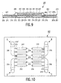
- Figure 9 shows a longitudinal section of part of a four-color ink jet printhead 201
- Figure 10 gives a plan view of the plate-shaped substrate body 207 of the same head 201.
- the pressure chambers 213, nozzles 214 and ink supply channels 215 are in fact arranged in a plurality of pairs which extend into the plane of Figure 9.
- Each chamber 213 is connected via the adjacent channel 215 to an ink supply duct 216, of which there are four (see Figure 10).
- the chambers 213 and nozzles 214 are arranged in 4 clusters A,B,C,D ( Figure 10), corresponding respectively to colors a,b,c and d (e.g. black, cyan, magenta and yellow, respectively).
- the number of nozzles 214 in each of the clusters A,B,C,D is, for example, 48.
- the actuator plate 225 is a CMA, As depicted in Figure 9, electrical contacting of the sides of the actuator plate 225 is here achieved using a blob 250 of conductive metal (e.g. solder or gold) to which at least one wire bond 260 is attached, the other end of each wire bond 260 making contact with a second portion 223 of the support plate 219.
- conductive metal e.g. solder or gold
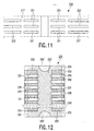
- Figure 11 renders a plan view of part of the support plate 219 in Figure 9.
- the first portions 221 are positioned in such a way as to overlap with the chambers 213 ( Figure 10) when the support plate 219 is superimposed upon the plate-shaped body 207 ( Figure 9), there being one first portion 221 for each chamber 213.
- the first portions 221 serve as pistons, whereas the second portions 223 serve as electrical leads.
- the membrane 217 may be embodied as a KAPTON foil, for example.
- Figure 12 shows a plan view of the actuator plate 225, which comprises active regions 231 and inactive regions 233. Depicted are addressable electrode layers 232 and a common electrode layer 234, the active regions 231 occurring where the former and the latter overlap; since the actuator plate 225 is a CMA, several such common and addressable electrode layers 232,234 will be interleaved in alternate arrangement (being mutually separated by ceramic material).
- the active regions (actuator elements) 231 are embodied as finger-like protrusions which extend along the long sides of the plate 225 in alternate arrangement with intervening slits 235.
- the actuator elements 231 are positioned in such a way as to overlap with the pistons 221 (Figure 11) when the actuator plate 225 is superimposed upon the support plate 219 ( Figure 9,11), there being one piston 221 for each actuator element 231. Also shown are wire-bond pads (metallic blobs) 250 at the free extremities of the actuator elements 231, allowing electrical connection of each element 231 to the respective electrical lead 223 via a wire bond 260 (not depicted); additional (larger) wire-bond pads 250' are provided at the butt-ends of the plate 225, and serve to make a common zero electrical connection to the common electrode layer 234.
- Figure 13 is an exploded perspective view of the mutual interrelationship between various parts of the subject of Figure 9. It shows the actuator plate 225 of Figure 12 which is overlaid by the top plate 237.
- the top plate 237 comprise first portions 241 and a second portion 243, the former taking the form of fingers which overlap with the actuator elements 231 of the actuator plate 225 and the latter (243) being embodied as a single (thicker) region which covers the central inactive region 233 of the actuator plate 225.
- the ensemble 237,235 is placed atop the support plate 219 in such a manner that the actuator elements 231 overlie the pistons 221 (but not the electrical leads 223).
- the membrane 217 is provided with two metallic ground lines 250" to which the wire-bond pads 250' of the actuator plate 225 can be electrically connected.
- ink feed-through holes 270 are arranged so as to overlie the four ink inputs 216' of the supply ducts 216 in Figure 10.
- the pistons 221 ( Figure 13) overlie the chambers 213.
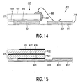
- Figure 14 is a partial longitudinal section of an alternative embodiment of an ink jet printhead according to the invention.
- the various reference numerals in the Figure differ from the corresponding reference numerals in Figures 1-8 only in that they are here preceded by a "3".
- top plate 237 in contrast to the use of a separate top plate 237 in Figure 9, the same purpose is served in Figure 14 by an extra-thick top portion 337 of inactive actuator material 333 in the CMA actuator plate 325.
- the role of top plate in the present case is thus played by an integral block 337 of ceramic material rather than a separately mounted plate 237 of, for example, iron-nickel.
- Figure 15 is a partial longitudinal section of another embodiment of an ink jet printhead according to the invention.
- the various reference numerals in the Figure differ from the corresponding reference numerals in Figures 1-8 only in that they are here preceded by a "4".
- the actuator plate 425 in this case is not a CMA; instead, it consists of an active piezoelectric portion 431 and a non-active or oppositely polarized piezoelectric portion 432, in stacked arrangement, both portions 431,432 being relatively thick ( e.g . of the order of 300 ⁇ m thick).
- a common electrode 472 is sandwiched between the portions 431 and 432, and a patterned (structured) electrode 470 is provided on top of the portion 432.
- the active piezoelectric portion 431 is soldered to the underlying piston 421 (via the solder joint 474), which is electrically connected to the associated electrical lead 423 via a relatively narrow electrical tract 422; because the tract 422 is narrow, vertical movement of the piston 421 with respect to the electrical lead 423 is minimally inhibited.
- the electrode 470 and solder joint 474 accurately overlap the piston 421; however, this is not strictly necessary.
- portion 432 which lies on top of the portion 431, is either non-active or oppositely polarized, there is no need for a separate top plate (such as plate 237 in Figure 9).
- Figure 16 is a partial longitudinal section of yet another embodiment of an ink jet printhead according to the invention.
- the various reference numerals in the Figure differ from the corresponding reference numerals in Figures 1-8 only in that they are here preceded by a "5".
- the actuator element 525 is a CMA 531 which is overlaid by a top plate 537.
- electrical contact with the actuator element 525 is achieved by using a metallic "blob" 550 (e.g. of solder or gold) to connect the exposed electrodes at the side of the CMA 531 to a base electrode 550' underlying the element 525.
- This base electrode 550' is in direct contact with the underlying piston 521.
- the piston 521 is electrically connected to the associated electrical lead 523 via a relatively narrow electrical tract 522.
- Figures 17 and 18 depict a modification of the subject of Figure 8.
- Corresponding features in the two Figures are denoted by the same reference numerals, which differ from the corresponding reference numerals in Figures 1-7 only in that they are here preceded by a "6".
- the membrane 17 and electrical leads 19 depicted in Figure 2 extend outside the periphery of the printhead 1 so as to form a flexfoil 117 carrying a plurality of conductor tracks 119. Because there is a great plurality of actuator elements 31 in Figure 2, the number of conductor tracks 119 on the flexfoil 117 is correspondingly great.
- Figure 17 shows a measure which reduces the said number of conductor tracks.
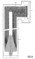
- a least one application-specific integrated circuit (ASIC) 680 is surface-mounted on the flexfoil 617 in relatively close proximity to the printhead 601 (in this particular case, there are two ASICs, 680,680').
- the number of conductor tracks between the printhead 601 and the ASIC 680 is then of the same order of magnitude as in Figure 8, but the number of conductor tracks between the ASIC 680 and the dangling (free) end of the flexfoil 617 is considerably reduced ( e.g. only of the order of about 5). This is because the presence of the ASIC 680 allows matrix control of the printhead 601.
- the nozzle plate 7b in Figure 2 comprises, for example, a sheet of Ni-Fe alloy which is provided with an anti-wetting layer (e.g. Ni-TEFLON) on the surface remote from the overlying substrate plate 7a.
- the holes 14 in such a nozzle plate 7b can be made using a drill, for example.
- An anti-wetting layer e.g. a silane
- a silane can be provided on the surface of the nozzle plate which will be remote from the overlying printhead structure (substrate plate).
- Such a layer can be deposited using a vapour deposition technique, for example.
Landscapes
- Particle Formation And Scattering Control In Inkjet Printers (AREA)
Description
the actuator plate having active regions and inactive regions, the actuator elements being formed by active regions of the actuator plate, adjacent actuator elements being separated from each other over substantially their whole length by slits provided in the actuator plate.
- glass;
- ceramic;
- plastic.
Claims (10)
- An ink jet printhead comprising:wherein:a body (7) having first (9) and second (11) opposite main faces, a plurality of pressure chambers (13) and a corresponding plurality of nozzles (14) being provided in the body, each pressure chamber extending between the first main face of the body and one of the nozzles and each nozzle extending between one of the pressure chambers and the second main face of the body;a membrane (17) having first and second main faces, said membrane being connected to the body with its second main face facing the first main face of the body;an actuator plate (25) having first (27) and second (29) main faces, the second main face of said actuator plate facing the first main face of the membrane, said actuator plate comprising a plurality of actuator elements (31) corresponding to the plurality of pressure chambers, the positions of the actuator elements in the actuator plate corresponding to the positions of the pressure chambers in the body, each actuator element being conceived to change its dimension in the direction of the thickness of the actuator plate upon application of a suitable voltage to the actuator element;between the second main face (29) of the actuator plate (25) and the first main face of the membrane (17) there is provided a support plate (19) comprising first portions (21) and second portions (23), said first portions being movable relative to the second portions in the direction of the thickness of the support plate, a first portion being situated between each actuator element (31) and the corresponding pressure chamber (13);the actuator plate having active regions (31) and inactive regions (33), the actuator elements being formed by active regions of the actuator plate, adjacent actuator elements being separated from each other over substantially their whole length by slits (35) provided in the actuator plate.
- An ink jet printhead as claimed in Claim 1, characterized in that the actuator plate (25) is a ceramic multilayer actuator.
- An ink jet printhead as claimed in Claim 1 or 2, characterized in that a top plate (37) is attached to the first main face (27) of the actuator plate (25), the top plate being provided with slits (39) corresponding to the slits (35) in the actuator plate.
- An ink jet printhead as claimed in Claim 3, characterized in that the top plate (25) comprises first portions (41) substantially extending over the active regions (31) of the actuator plate (25) and second portions (43) substantially extending over the inactive regions (33) of the actuator plate, the first portions of the top plate having a smaller thickness than the second portions.
- An ink jet printhead as claimed in Claim 1 or 2, characterized in that the actuator plate (325) comprises a relatively thick inactive region (337) adjacent to the first main face (327) and overlying each active region (331) extending over a first portion (321) of the support plate (319).
- An ink jet printhead as claimed in Claim 1 or 2, characterized in that the actuator element (425) comprises a plate (431) of active piezoelectric material over which extends a plate (432) of non-active material, the active plate (431) being electrically connected (474) to a first portion (421) of the support plate, the active plate (431) and non-active plate (432) being sandwiched about an intervening common electrode (472), another electrode (470) being provided on the surface of the non-active plate (432) remote from the common electrode (472).
- An ink jet printhead as claimed in Claim 1 or 2, characterized in that the actuator element (425) comprises a plate (431) of active piezoelectric material over which extends a plate (432) of oppositely polarized piezoelectric material, the active plate (431) being electrically connected (474) to a first portion (421) of the support plate, the active plate (431) and oppositely polarized plate (432) being sandwiched about an intervening common electrode (472), another electrode (470) being provided on the surface of the oppositely polarized plate (432) remote from the common electrode (472).
- An ink jet printhead as claimed in any of the Claims 1-7, characterized in that each active region (231) of the actuator plate (225) which extends over a first portion (221) of the support plate (219) is electrically connected to the adjacent second portion (223) of the support plate (219) using a wire bond (250,260).
- An ink jet printhead as claimed in any of the Claims 1-7, characterized in that each active region (531) of the actuator plate (525) which extends over a first portion (521) of the support plate (519) is electrically connected (550) to a base electrode (550') which is situated between, and is in electrical contact with both of, the said first portion (521) of the actuator plate (525) and first portion (521) of the support plate (519), and that the first portion (521) of the support plate (519) is electrically connected to the adjacent second portion (523) of the support plate (519) via a relatively narrow conductive tract (522).
- An ink jet printer comprising a printhead as claimed in any one of the preceding Claims.
Priority Applications (1)
| Application Number | Priority Date | Filing Date | Title |
|---|---|---|---|
| EP97942160A EP0917509B1 (en) | 1996-10-30 | 1997-10-13 | Ink jet printhead and ink jet printer |
Applications Claiming Priority (6)
| Application Number | Priority Date | Filing Date | Title |
|---|---|---|---|
| EP96203032 | 1996-10-30 | ||
| EP96203032 | 1996-10-30 | ||
| EP97201584 | 1997-05-29 | ||
| EP97201584 | 1997-05-29 | ||
| EP97942160A EP0917509B1 (en) | 1996-10-30 | 1997-10-13 | Ink jet printhead and ink jet printer |
| PCT/IB1997/001270 WO1998018633A1 (en) | 1996-10-30 | 1997-10-13 | Ink jet printhead and ink jet printer |
Publications (2)
| Publication Number | Publication Date |
|---|---|
| EP0917509A1 EP0917509A1 (en) | 1999-05-26 |
| EP0917509B1 true EP0917509B1 (en) | 2001-12-12 |
Family
ID=26143289
Family Applications (1)
| Application Number | Title | Priority Date | Filing Date |
|---|---|---|---|
| EP97942160A Expired - Lifetime EP0917509B1 (en) | 1996-10-30 | 1997-10-13 | Ink jet printhead and ink jet printer |
Country Status (6)
| Country | Link |
|---|---|
| US (1) | US6079820A (en) |
| EP (1) | EP0917509B1 (en) |
| JP (1) | JP2000506800A (en) |
| KR (1) | KR19990076888A (en) |
| DE (1) | DE69709119T2 (en) |
| WO (1) | WO1998018633A1 (en) |
Families Citing this family (18)
| Publication number | Priority date | Publication date | Assignee | Title |
|---|---|---|---|---|
| US6855264B1 (en) | 1997-07-15 | 2005-02-15 | Kia Silverbrook | Method of manufacture of an ink jet printer having a thermal actuator comprising an external coil spring |
| JP3328609B2 (en) * | 1998-12-30 | 2002-09-30 | 三星電子株式会社 | Ink jet printer head actuator and method of manufacturing the same |
| US6825951B1 (en) * | 2000-04-05 | 2004-11-30 | Hewlett-Packard Development Company, L.P. | Inkjet printing and method |
| US6428133B1 (en) | 2000-05-23 | 2002-08-06 | Silverbrook Research Pty Ltd. | Ink jet printhead having a moving nozzle with an externally arranged actuator |
| US6557970B2 (en) | 2000-05-23 | 2003-05-06 | Silverbrook Research Pty Ltd | Nozzle guard for a printhead |
| US6526658B1 (en) | 2000-05-23 | 2003-03-04 | Silverbrook Research Pty Ltd | Method of manufacture of an ink jet printhead having a moving nozzle with an externally arranged actuator |
| IL153028A (en) * | 2000-05-24 | 2005-06-19 | Silverbrook Res Pty Ltd | Ink jet printhead having a moving nozzle with an externally arranged actuator |
| CN100417523C (en) * | 2000-05-24 | 2008-09-10 | 西尔弗布鲁克研究有限公司 | Inkjet printhead with isolated nozzle controller |
| ATE367266T1 (en) | 2000-05-24 | 2007-08-15 | Silverbrook Res Pty Ltd | MANUFACTURING METHOD FOR A MOVING NOZZLE INK JET PRINT HEAD AND EXTERNAL ACTUATOR |
| AU2004233536B2 (en) * | 2000-10-20 | 2005-10-20 | Zamtec Limited | A printhead having a nozzle arrangement with nozzle openings in moveable wall of the nozzle chamber |
| US6623101B1 (en) * | 2000-10-20 | 2003-09-23 | Silverbrook Research Pty Ltd | Moving nozzle ink jet |
| JP2003165212A (en) * | 2001-11-30 | 2003-06-10 | Brother Ind Ltd | Inkjet head |
| US6712455B2 (en) | 2001-03-30 | 2004-03-30 | Philip Morris Incorporated | Piezoelectrically driven printhead array |
| JP4296738B2 (en) * | 2001-11-30 | 2009-07-15 | ブラザー工業株式会社 | Inkjet head |
| US6994428B2 (en) * | 2002-05-21 | 2006-02-07 | Brother Kogyo Kabushiki Kaisha | Ink-jet printing head having a plurality of actuator units and/or a plurality of manifold chambers |
| TWI222408B (en) * | 2002-12-03 | 2004-10-21 | Nanodynamics Inc | Pressure chamber of a piezoelectric ink jet print head and fabrication method thereof |
| IT201800005824A1 (en) | 2018-05-29 | 2019-11-29 | MEMS MICROFLUIDIC DEVICE FOR THE EXPULSION OF FLUIDS EQUIPPED WITH PIEZOELECTRIC ACTUATION AND WITH REDUCED SWELLING EFFECT | |
| JP2020146876A (en) * | 2019-03-12 | 2020-09-17 | 株式会社リコー | Liquid ejection head and liquid ejection device |
Family Cites Families (7)
| Publication number | Priority date | Publication date | Assignee | Title |
|---|---|---|---|---|
| DE3342844A1 (en) * | 1983-11-26 | 1985-06-05 | Philips Patentverwaltung Gmbh, 2000 Hamburg | MICROPLANAR INK JET PRINT HEAD |
| DE69310022T2 (en) * | 1992-06-05 | 1997-08-21 | Seiko Epson Corp | Ink jet recording head |
| JP3235635B2 (en) * | 1993-11-29 | 2001-12-04 | セイコーエプソン株式会社 | Inkjet recording head |
| JPH07329292A (en) * | 1994-04-13 | 1995-12-19 | Seiko Epson Corp | Inkjet recording head |
| US5818482A (en) * | 1994-08-22 | 1998-10-06 | Ricoh Company, Ltd. | Ink jet printing head |
| DE4443254C1 (en) * | 1994-11-25 | 1995-12-21 | Francotyp Postalia Gmbh | Ink print head assembly using edge-shooter principle for small high speed computer printer |
| JP3663652B2 (en) * | 1995-02-13 | 2005-06-22 | ブラザー工業株式会社 | Inkjet printer head |
-
1997
- 1997-10-13 DE DE69709119T patent/DE69709119T2/en not_active Expired - Fee Related
- 1997-10-13 JP JP10520227A patent/JP2000506800A/en active Pending
- 1997-10-13 EP EP97942160A patent/EP0917509B1/en not_active Expired - Lifetime
- 1997-10-13 WO PCT/IB1997/001270 patent/WO1998018633A1/en not_active Ceased
- 1997-10-13 KR KR1019980705015A patent/KR19990076888A/en not_active Ceased
- 1997-10-23 US US08/956,882 patent/US6079820A/en not_active Expired - Fee Related
Also Published As
| Publication number | Publication date |
|---|---|
| US6079820A (en) | 2000-06-27 |
| KR19990076888A (en) | 1999-10-25 |
| DE69709119D1 (en) | 2002-01-24 |
| WO1998018633A1 (en) | 1998-05-07 |
| JP2000506800A (en) | 2000-06-06 |
| DE69709119T2 (en) | 2002-08-29 |
| EP0917509A1 (en) | 1999-05-26 |
Similar Documents
| Publication | Publication Date | Title |
|---|---|---|
| US6079820A (en) | Ink jet printhead and ink jet printer | |
| EP1226944B1 (en) | Fabrication method | |
| US8414110B2 (en) | Inkjet head | |
| EP1632354B1 (en) | Inkjet head and manufacturing method of the same | |
| EP0576037B1 (en) | Ink-jet recording head | |
| EP0803918B1 (en) | Piezoelectric vibrator unit, ink jet recording head using the piezoelectric vibrator unit and method of manufacturing the same | |
| EP1997637B1 (en) | Method of manufacturing a piezoelectric ink jet device | |
| EP1316427A1 (en) | Inkjet head for inkjet printing apparatus | |
| EP0936684A1 (en) | Piezoelectric actuator having an array of drive columns | |
| US8869362B2 (en) | Method of forming an array of piezoelectric actuators on a membrane | |
| EP1568501B1 (en) | Piezoelectric actuator for inkjet printhead and method for forming the same | |
| GB2288766A (en) | Electrode arrangements for piezoelectric drive elements of an ink jet printer. | |
| JPH11263013A (en) | Piezoelectric actuator for ink jet printing head | |
| EP1083048A1 (en) | Ink jet recording head and manufacturing method thereof | |
| EP1559551B1 (en) | Inkjet head | |
| US7798618B2 (en) | Ink jet head | |
| US7651200B2 (en) | Ink jet head | |
| CN1311972C (en) | Piezoelectric ink jet head | |
| JPH09272206A (en) | Array of piezoelectric vibrators | |
| JP2006205670A (en) | Inkjet head | |
| JP3844187B2 (en) | Actuator unit and ink jet recording head | |
| US20030007037A1 (en) | Inkjet printhead | |
| JP2001341300A (en) | Actuator unit and ink jet recording head | |
| JPH081933A (en) | Piezoelectric vibrator array | |
| JP3381678B2 (en) | Ink jet recording head and method of manufacturing the same |
Legal Events
| Date | Code | Title | Description |
|---|---|---|---|
| PUAI | Public reference made under article 153(3) epc to a published international application that has entered the european phase |
Free format text: ORIGINAL CODE: 0009012 |
|
| 17P | Request for examination filed |
Effective date: 19981109 |
|
| AK | Designated contracting states |
Kind code of ref document: A1 Designated state(s): DE FR GB NL |
|
| GRAG | Despatch of communication of intention to grant |
Free format text: ORIGINAL CODE: EPIDOS AGRA |
|
| 17Q | First examination report despatched |
Effective date: 20001122 |
|
| GRAG | Despatch of communication of intention to grant |
Free format text: ORIGINAL CODE: EPIDOS AGRA |
|
| GRAH | Despatch of communication of intention to grant a patent |
Free format text: ORIGINAL CODE: EPIDOS IGRA |
|
| GRAH | Despatch of communication of intention to grant a patent |
Free format text: ORIGINAL CODE: EPIDOS IGRA |
|
| GRAA | (expected) grant |
Free format text: ORIGINAL CODE: 0009210 |
|
| AK | Designated contracting states |
Kind code of ref document: B1 Designated state(s): DE FR GB NL |
|
| PG25 | Lapsed in a contracting state [announced via postgrant information from national office to epo] |
Ref country code: NL Free format text: LAPSE BECAUSE OF FAILURE TO SUBMIT A TRANSLATION OF THE DESCRIPTION OR TO PAY THE FEE WITHIN THE PRESCRIBED TIME-LIMIT Effective date: 20011212 |
|
| REG | Reference to a national code |
Ref country code: GB Ref legal event code: IF02 |
|
| REF | Corresponds to: |
Ref document number: 69709119 Country of ref document: DE Date of ref document: 20020124 |
|
| ET | Fr: translation filed | ||
| NLV1 | Nl: lapsed or annulled due to failure to fulfill the requirements of art. 29p and 29m of the patents act | ||
| PLBE | No opposition filed within time limit |
Free format text: ORIGINAL CODE: 0009261 |
|
| STAA | Information on the status of an ep patent application or granted ep patent |
Free format text: STATUS: NO OPPOSITION FILED WITHIN TIME LIMIT |
|
| 26N | No opposition filed | ||
| NLV1 | Nl: lapsed or annulled due to failure to fulfill the requirements of art. 29p and 29m of the patents act | ||
| PGFP | Annual fee paid to national office [announced via postgrant information from national office to epo] |
Ref country code: FR Payment date: 20031027 Year of fee payment: 7 |
|
| PGFP | Annual fee paid to national office [announced via postgrant information from national office to epo] |
Ref country code: GB Payment date: 20031031 Year of fee payment: 7 |
|
| PGFP | Annual fee paid to national office [announced via postgrant information from national office to epo] |
Ref country code: DE Payment date: 20031215 Year of fee payment: 7 |
|
| PG25 | Lapsed in a contracting state [announced via postgrant information from national office to epo] |
Ref country code: GB Free format text: LAPSE BECAUSE OF NON-PAYMENT OF DUE FEES Effective date: 20041013 |
|
| PG25 | Lapsed in a contracting state [announced via postgrant information from national office to epo] |
Ref country code: DE Free format text: LAPSE BECAUSE OF NON-PAYMENT OF DUE FEES Effective date: 20050503 |
|
| GBPC | Gb: european patent ceased through non-payment of renewal fee |
Effective date: 20041013 |
|
| PG25 | Lapsed in a contracting state [announced via postgrant information from national office to epo] |
Ref country code: FR Free format text: LAPSE BECAUSE OF NON-PAYMENT OF DUE FEES Effective date: 20050630 |
|
| REG | Reference to a national code |
Ref country code: FR Ref legal event code: ST |