EP0917342A2 - Printer and scanning synchronization data calculating method therefor - Google Patents
Printer and scanning synchronization data calculating method therefor Download PDFInfo
- Publication number
- EP0917342A2 EP0917342A2 EP98305556A EP98305556A EP0917342A2 EP 0917342 A2 EP0917342 A2 EP 0917342A2 EP 98305556 A EP98305556 A EP 98305556A EP 98305556 A EP98305556 A EP 98305556A EP 0917342 A2 EP0917342 A2 EP 0917342A2
- Authority
- EP
- European Patent Office
- Prior art keywords
- laser scanning
- photoreceptor belt
- scanning units
- scanning
- units
- Prior art date
- Legal status (The legal status is an assumption and is not a legal conclusion. Google has not performed a legal analysis and makes no representation as to the accuracy of the status listed.)
- Withdrawn
Links
Images


Classifications
-
- H—ELECTRICITY
- H04—ELECTRIC COMMUNICATION TECHNIQUE
- H04N—PICTORIAL COMMUNICATION, e.g. TELEVISION
- H04N1/00—Scanning, transmission or reproduction of documents or the like, e.g. facsimile transmission; Details thereof
- H04N1/46—Colour picture communication systems
- H04N1/50—Picture reproducers
- H04N1/506—Reproducing the colour component signals picture-sequentially, e.g. with reproducing heads spaced apart from one another in the subscanning direction
Definitions
- the present invention relates to a printer and a method for calculating scanning synchronization data, and more particularly, to a printer which can control the scanning synchronization of a laser scanning unit using the photoreceptor belt track position information obtained from light irradiated from the laser scanning unit, and a method for calculating the scanning synchronization data.
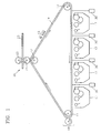
- a reset device 15, laser scanning units 30, development devices 17, a drying device 18 and a transfer device 20 are spaced apart by a predetermined distance in proximity with the circulating track of a circulating photoreceptor belt 14 along three rollers 11, 12 and 13.
- the laser scanning units 30 scan laser beams onto the photoreceptor belt 14 circulating by the reset device 15.
- An electrostatic latent image is formed on the photoreceptor belt 14 by the scanned beams, and the electrostatic latent image is developed by a developer liquid supplied from the development devices 17.
- the colour image formed on the photoreceptor belt 14 is firstly transferred to a transfer roller 21 by the continuous circulation of the photoreceptor belt 14. Subsequently, the colour image on the transfer roller 21 is secondly transferred to a sheet 23 fed between the transfer roller 21 for advancing the sheet 23 and a pressing roller 22, by the reciprocal rotation of the transfer roller 21 and the pressing roller 22 in engagement with each other.
- each laser scanning unit 30 installed with a predetermined distance from one another for colour image printing, sequentially scan laser beams corresponding to colours of yellow, magenta, cyan and black onto the photoreceptor belt 14.
- the respective development devices 17 making up a set with the respective laser scanning units 30 supply different coloured developer liquids corresponding to the colour information of the laser scanning units 30.
- the respective laser scanning units 30 constituted by elements serving the same functions each commonly include a light source 31, a rotary polygon mirror 32 and a lens unit 33, and is installed to sequentially scan laser beams in the direction of the width of the photoreceptor belt 14.
- the laser scanning system includes the laser scanning units 30, a laser scanning controller 35 for controlling the laser scanning of the laser scanning units 30, photodetectors 34 for detecting a part of the laser beams emitted from the laser scanning units 30 and supplying a photodetection signal, and a track detector 40 for supplying track position information of the photoreceptor belt 14.
- the track detector 40 includes a light source 41 and a photodetector 42, for detecting an identifying pattern 14a formed on a region beyond an imaging region (D) of the photoreceptor belt 14.
- the laser scanning controller 35 determines the current track position of the photoreceptor belt 14 based on the input timing of the pulse signal of the photodetector 42. According to the determined track position, in forming the electrostatic latent image corresponding to one page of the sheet 23, the start of scanning is delayed by the time necessary for a predetermined recording start target region to reach the laser scanning position of the laser scanning units 30 on the photoreceptor belt 14, and then the laser scanning units 30 are initiated.
- the initiated laser scanning units 30 continuously irradiate laser beams toward the edge of the photoreceptor belt 14 from a position spaced apart from the edge.
- the photodetector 34 for detecting a part of the laser beams irradiated toward the edge of the photoreceptor belt 14 outputs the pulse signal corresponding to the detected light to the laser scanning controller 35.
- the laser scanning controller 35 determines the falling edge of the pulse signal as the timing for the light emitted from the laser scanning units 30 to reach the edge of the photoreceptor belt 14, and drives the light source 31 to emit the light signal corresponding to the image data to be printed after the time corresponding to the time from the falling edge of the pulse signal until an image scanning from the light source 31 toward the starting position of the preset imaging region D is initiated.
- the configuration thereof is complex. Also, since the track position of the photoreceptor belt 14 is checked just once during one circulation of the photoreceptor belt 14, if the photoreceptor belt 14 continuously circulating by the rollers 11, 12 and 13 advances at a speed slower than a predetermined movement speed set by the slip with respect to the rollers 11, 12 and 13, the laser beams irradiated from the scanning timing set in the previous printing procedure reach the position outside of the scanning target region of the photoreceptor belt 14, which makes it difficult to achieve a desired print quality.
- a printer including a plurality of rollers, a photoreceptor belt circulating on an endless track by and around the plurality of rollers and having a transparent band continuously formed in the vicinity of one edge of the photoreceptor belt and at least one transparent window disposed a predetermined distance from the transparent band, a plurality of laser scanning units disposed a predetermined distance from the photoreceptor belt for scanning beams onto the photoreceptor belt, photodetectors for detecting beams having passed through the transparent band and transparent window, among beams emitted from the laser scanning units, and a laser scanning controller for controlling the laser scanning units according to signals output from the photodetectors.
- the window may comprise a throughole.
- a method for calculating scanning synchronization data for the printer including the steps of: a) adjusting the driving of the laser scanning units while circulating the photoreceptor belt, so that the beams emitted from the laser scanning units arrive at the photoreceptor belt parallel to the travelling direction of the photoreceptor belt, b) calculating distances among scanning lines formed on the photoreceptor belt by the beams irradiated from the laser scanning units, from information on the timings at which the signals sequentially output from the photodetectors receiving the beams emitted from the laser scanning units whose driving is adjusted in the step a) and having passed through the transparent window moving at a predetermined speed, and c) calculating scanning synchronization data for sequentially starting the laser scanning from the laser scanning units onto the same region of the circulating photoreceptor belt with respect to the picture data for the respective colours of the identical page, from the distances among the scanning lines.
- the scanning synchronization data may be obtained while the photoreceptor belt moves at
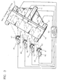
- a printer includes a photoreceptor belt 54 having a transparent band 52 and a transparent window circulating by rollers 51, four laser scanning units 60, 70, 80 and 90, disposed a predetermined distance from the photoreceptor belt 54 in parallel with each other, for scanning beams, four photodetectors 64, 74, 84 and 94 disposed at the rear of the photoreceptor belt 54 paired with the respective laser scanning units 60, 70, 80 and 90, for detecting parts of beams emitted from the respective laser scanning units 60, 70, 80 and 90, and a laser scanning controller 55 for receiving outputs of the respective photodetectors 64, 74, 84 and 94 and controlling the driving of the respective laser scanning units 60, 70, 80 and 90.
- the printer includes development units, a transfer unit, a reset unit (see Figure 1).
- the respective laser scanning units 60, 70, 80 and 90 scan colour information of yellow (Y), magenta (M), cyan (C) and black (K), respectively, and have the same components.
- the laser scanning units 60, 70, 80 and 90 includes light sources 61, 71, 81 and 91, respectively, for irradiating light, rotary polygons 62, 72, 82 and 92 for deflecting incident light in a direction of the width of the photoreceptor belt 54, i.e., in a main scanning direction, and lens units 63, 73, 83 and 92 provided between the rotary polygons 62, 72, 82 and 92 and the photoreceptor belt 54, respectively, for focusing the laser beam deflected from the rotary polygons 62, 72, 82 and 92 onto the photoreceptor belt 54.
- collimating lenses for collimating the laser beam irradiated from the light sources 61, 71, 81 and 91, respectively, and cylindrical lenses for making the laser beam of the main scanning direction travel straight and converging the laser beam of the sub-scanning direction (the travelling direction of the photoreceptor belt 54) may be provided between the light sources 61, 71, 81 and 91, and the rotary polygon mirrors 62, 72, 82 and 92, respectively.
- the rotary polygon mirrors 62, 72, 82 and 92 each having a multitude of reflection planes are rotated by a driving motor (not shown) controlled by the laser scanning controller 55.
- the transparent band 52 provided at a position deviated from an imaging region D set in the center of the photoreceptor belt 54 is formed of a transparent material so as to transmit incident light.
- the transparent band 52 is formed a predetermined width lengthwise with respect to the photoreceptor belt 54, i.e., parallel to the edge line of the same.
- the transparent window 53 provided a predetermined distance adjacent to the transparent band 52, is formed in the form of a throughhole or transparent material so as to transmit incident light.
- the photodetectors 64, 74, 84 and 94 receive the beams passing through the transparent band 52 and the transparent window 53, among beams from the laser scanning units 60, 70, 80 and 90 disposed to correspond thereto.
- the laser scanning controller 55 receives pulse signals output when the transparent window 53 passes through the positions of scanning lines L1 through L4 formed by the beams irradiated from the respective laser scanning units 60, 70, 80 and 90 onto the photoreceptor belt 54, according to light detection by the photodetectors 64, 74, 84 and 94, and checks the track position of the photoreceptor belt 54.
- a separate track detector is not necessary.
- the transparent band 52 is provided in the inner side of the edges of the photoreceptor 54 so that it is always maintained at a constant distance from the leading edge of the imaging region D, irrespective of the abrasion of the edges of the photoreceptor belt 54.
- the photodetector 64 periodically outputs a pulse signal 64a indicative of the detection of the beam having passed through the transparent band 52.
- the photodetector 64 outputs a pulse signal 64b corresponding to the arrival of the transparent window 53.
- the other photodetectors 74, 84 and 94 corresponding to the laser scanning units 70, 80 and 90 for scanning magenta, cyan and black colour information.
- the widths of the transparent window 52 and the transparent band 53 it is preferable to determine the widths of the transparent window 52 and the transparent band 53 so that the width of the pulse signal 64a output from the photodetector 64 corresponding to the passage of the transparent band 52 is different from that of the pulse signal 54b output corresponding to the passage of the transparent window 53. This is because the passage of the transparent window 53 and transparent band 52 is discriminated more easily by the laser scanning controller 55 when the widths of the pulse signals 64b and 64a output corresponding to the beam passage of the transparent window 53 and transparent band 52 are different from each other.
- the laser scanning controller 55 can check the current track position of the photoreceptor belt 54 when the pulse signals 64b, 74b, 84b and 94b corresponding to the passage of the transparent window 53 are input.
- the laser scanning timing of the respective laser scanning units 60, 70, 80 and 90 is controlled by the input pulse signal 64b. For example, when the transparent window 53 arrives at the position of the scanning line L1 of the laser scanning unit 60 for scanning the yellow colour information so that the pulse signal 64b corresponding thereto is input from the photodetector 64, the laser scanning controller 55 uses a falling edge of the pulse signal 64b as the page-synchronization reference signal for starting the laser scanning for one-page portion beams.
- the laser scanning controller 55 determines the falling edge of the pulse signal 64a output from the photodetector 64 by the continuously scanned beams, correspondingly to the passage of the transparent band 52, after the pulse signal 64b is input, as the timing when the beam emitted from the laser scanning unit 60 arrives at the edge of the transparent band 52 of the photoreceptor belt 54. Also, the laser scanning controller 55 drives the light source 61 to emit a beam corresponding to the yellow picture data, after a predetermined time, i.e., a time corresponding to the time from the falling edge of the pulse signal 64a until an image scanning from the light source 61 toward the starting position of the imaging region D is initiated.
- the photodetector 74 corresponding to the laser scanning unit 70 for scanning the magenta (M) colour information outputs a pulse signal 74b indicative of the arrival of the transparent window 53 by the beam scanned by the laser scanning unit 70
- the laser scanning controller 55 internally generates a page-synchronization signal indicative of the start of the page which is the same as the yellow colour information, based on the falling edge of the pulse signal 74b.
- the laser scanning controller 55 drives the laser scanning unit 70 to emit a beam corresponding to the magenta picture data, after a predetermined time, i.e., a time corresponding to the time from the falling edge of the pulse signal 74a output from the photodetector 74 by the beam having passed through the transparent band 52 until an image scanning from the light source 71 toward the starting position of the imaging region D is initiated.
- the scanning timing of the laser scanning unit 70 is adjusted so that the beam for magenta colour information can be scanned on the yellow image lines previously formed on the photoreceptor belt 54.
- the laser scanning timing is adjusted so that the distances between the transparent band 52 and the positions of the beams simultaneously emitted from the laser scanning unit 60 for yellow colour information and the laser scanning unit 70 for magenta colour information, and arriving at the photoreceptor belt 54 are made different by compensated offset components.
- the scanning timings of the laser scanning units 80 and 90 for scanning cyan (C) and black (K) colour information are also controlled by the laser scanning controller 55 in the same manner as above.
- the beam signals for the respective colours output from four laser scanning units 60, 70, 80 and 90 are sequentially written on the same region of the circulating photoreceptor belt 54, thereby printing a desired image.
- a method for calculating scanning synchronization data for synchronizing the scanning timings of the respective laser scanning units 60, 70, 80 and 90, reflecting an alignment error between the respective laser scanning units 60, 70, 80 and 90, generated during fabrication, or in the course of remounting the respective laser scanning units 60, 70, 80 and 90 after repairing the used laser scanning units 60, 70, 80 and 90, or mounting new laser scanning units for replacement, will be described.
- the alignment error between the respective laser scanning units 60, 70, 80 and 90 refers to the deviation degree of the distances d1, d2 and d3 among the scanning lines L1 through L4 formed on the photoreceptor belt 14 by the beam emitted from the mounted laser scanning units 60, 70, 80 and 90 from set values as the distances d1, d1+d2 and d1+d2+d3 between one scanning line L1 and the other scanning line L2, L3 or L4.
- the mounting positions of the laser scanning units 60, 70, 80 and 90 vary slightly during fabrication, repair or replacement, the intervals among the scanning lines L1 through L4 formed on the photoreceptor belt 54 vary accordingly. Therefore, if it is possible to measure the distance among the scanning lines L1 through L4 determined by mounted laser scanning units 60, 70, 80 and 90, the scanning synchronization data can be calculated. If the scanning synchronization data is calculated, the driving of the laser scanning units 60, 70, 80 and 90 is controlled so that beams are emitted to the same region of the circulating photoreceptor belt 54 from the laser scanning units 60, 70, 80 and 90 with respect to the picture information for the identical page.
- an operation panel (not shown) a key through which a user can command execution of a test mode for calculating the scanning synchronization data with respect to the laser scanning units 60, 70, 80 and 90 mounted after fabrication of the printer or newly mounted for replacement. If the test mode is selected, the printer calculates the scanning synchronization data in the following steps.
- the respective laser scanning units 60, 70, 80 and 90 are driven so that the laser beams simultaneously emitted from the respective laser scanning units 60, 70, 80 and 90 arrive in parallel at the photoreceptor belt 54 which are disposed at equal distances widthwise based on the edge lines of the photoreceptor belt 54.
- the respective laser scanning units 60, 70, 80 and 90 are driven so that the output pulses 64a, 74a, 84a and 94a of the respective photodetectors 64, 74, 84 and 94 corresponding to the passage of the transparent band 52 by the beams emitted from the respective laser scanning units 60, 70, 80 and 90 are output simultaneously.
- the moving speed of the photoreceptor belt 54 is maintained at a speed one fourth the normal printing speed.
- the time at which the transparent window 53 passes through the positions of the scanning lines L1 through L4 of the respective laser scanning units 60, 70, 80 and 90 is checked.
- the time intervals among pulses 64b, 74b, 84b and 94b output from the photodetectors 64, 74, 84 and 94 corresponding to the passage of the transparent window 53 is output from the first photodetector 64, are t1, t2 and t3, respectively.
- the distances d1, d2 and d3 among the scanning lines L1 through L4 of the respective laser scanning units 60, 70, 80 and 90 can be calculated by the counted times t1, t2 and t3, and the moving speed of the photoreceptor belt 54 using the distances d1, d2 and d3 obtained through the above process, the scanning synchronization data for starting the sequential scanning timings of the respective laser scanning units 60, 70, 80 and 90 at the same region of the photoreceptor belt 54 with respect to the picture data of the identical page, is calculated by internal operation.
- the sequential scanning start timings of the respective laser scanning units 60, 70, 80 and 90 for scanning information of magenta (M), cyan (c) and black (K) colours and the driving control data of rotary polygon mirrors 62, 72, 82 and 92 corresponding thereto are internally calculated.
- misalignment is calculated by the remainder obtained by dividing by the line pitch adopted in printing operation the distances d1, d1+d2, and d1+d2+d3 between the scanning line L1 formed on the photoreceptor belt 54 by the laser scanning unit 60 for scanning the yellow colour information, and the other scanning lines L2 through L4 of the laser scanning units 70, 80 and 90.
- the next step is to obtain the driving data which differs by compensated offset values, i.e., the extent of misalignment with respect to the line pitch interval the distances between the transparent band 52 of the photoreceptor 54 and the positions of the beams simultaneously emitted from the laser scanning units 60, 70, 80 and 90 and arriving at the photoreceptor belt 54.
- synchronization adjusting data of the rotary polygon mirrors 62, 72, 82 and 92 is calculated for rotating the rotary polygon mirrors 62, 72, 82 and 92 while maintaining the mutually deviated state of the reflection plane of the reference rotary polygon mirror (62 corresponding to the laser scanning unit 60 for scanning yellow colour information) and the reflection plane of the other rotary polygon mirrors 72, 82 and 92 by compensated offset components.
- the synchronization adjusting data of the rotary polygon mirrors 62, 72, 82 and 92 are stored in a memory device as scanning synchronization data. Then, during a normal printing operation, while the reflection planes of the rotary polygon mirrors 62, 72, 82 and 92 are maintained to be misaligned at angles corresponding to the stored data, the rotary polygon mirrors 62, 72, 82 and 92 are rotated at the same speed, the beam corresponding to the picture information is scanned on the same region of the photoreceptor belt 54, thereby obtaining a desired picture.
- the pulse signals 64a, 74a, 84a and 94a output from the photodetectors 64, 74, 84 and 94 by the beams having passed through the transparent band 52 are generated, when a predetermined time corresponding to the time from the falling edge of the pulse signals 64a, 74a, 84a and 94a until an image scanning from the light source 61, 71, 81 and 91 toward the starting position of the imaging region D is initiated, the beams corresponding to the picture information of the respective colours are emitted from the respective laser scanning units 60, 70, 80 and 90.
- the laser scanning unit 90 for scanning black colour information is slightly misaligned from a set position to be mounted so that the distance d1+d2+d3 between the yellow scanning line L1 and the black scanning line L4 is not an integer multiple of the line pitch interval applied to during the printing operation
- the photodetector 94 outputs a pulse signal 94c indicated by a dotted line in a delayed time compared to the output timing of the pulse signal 64a as the corresponding scanning timing is adjusted so as to compensate for the offset component.
- the scanning synchronization data calculating method As described above, in the laser scanning system of a printer and the scanning synchronization data calculating method according to the present invention, since the track position of a photoreceptor belt can be checked using parts of scanned beams, the number of elements necessary for checking the track position of the photoreceptor belt is reduced. Also, after mounting or replacing the respective laser scanning units, necessary scanning synchronization data is internally calculated in the system, and the simplicity of the system is enhanced.
Abstract
Description
- The present invention relates to a printer and a method for calculating scanning synchronization data, and more particularly, to a printer which can control the scanning synchronization of a laser scanning unit using the photoreceptor belt track position information obtained from light irradiated from the laser scanning unit, and a method for calculating the scanning synchronization data.
- Referring to Figure 1 showing a general colour printer, a
reset device 15,laser scanning units 30,development devices 17, adrying device 18 and atransfer device 20 are spaced apart by a predetermined distance in proximity with the circulating track of a circulatingphotoreceptor belt 14 along threerollers - Now, a printing procedure will be described. First, the
laser scanning units 30 scan laser beams onto thephotoreceptor belt 14 circulating by thereset device 15. An electrostatic latent image is formed on thephotoreceptor belt 14 by the scanned beams, and the electrostatic latent image is developed by a developer liquid supplied from thedevelopment devices 17. The colour image formed on thephotoreceptor belt 14 is firstly transferred to atransfer roller 21 by the continuous circulation of thephotoreceptor belt 14. Subsequently, the colour image on thetransfer roller 21 is secondly transferred to asheet 23 fed between thetransfer roller 21 for advancing thesheet 23 and apressing roller 22, by the reciprocal rotation of thetransfer roller 21 and thepressing roller 22 in engagement with each other. - In such a colour printer, four
laser scanning units 30 installed with a predetermined distance from one another for colour image printing, sequentially scan laser beams corresponding to colours of yellow, magenta, cyan and black onto thephotoreceptor belt 14. Therespective development devices 17 making up a set with the respectivelaser scanning units 30 supply different coloured developer liquids corresponding to the colour information of thelaser scanning units 30. - Referring to Figure 2 showing a laser scanning system of the printing shown in Figure 1, the respective
laser scanning units 30 constituted by elements serving the same functions each commonly include alight source 31, arotary polygon mirror 32 and alens unit 33, and is installed to sequentially scan laser beams in the direction of the width of thephotoreceptor belt 14. - The laser scanning system includes the
laser scanning units 30, alaser scanning controller 35 for controlling the laser scanning of thelaser scanning units 30,photodetectors 34 for detecting a part of the laser beams emitted from thelaser scanning units 30 and supplying a photodetection signal, and atrack detector 40 for supplying track position information of thephotoreceptor belt 14. Thetrack detector 40 includes alight source 41 and aphotodetector 42, for detecting an identifying pattern 14a formed on a region beyond an imaging region (D) of thephotoreceptor belt 14. - Now, the operation of the laser scanning system will be described. First, if a pulse signal generated by the passage of identifying patterns 14a is input from the
photodetector 42 of thetrack detector 40 to thelaser scanning controller 35, thelaser scanning controller 35 determines the current track position of thephotoreceptor belt 14 based on the input timing of the pulse signal of thephotodetector 42. According to the determined track position, in forming the electrostatic latent image corresponding to one page of thesheet 23, the start of scanning is delayed by the time necessary for a predetermined recording start target region to reach the laser scanning position of thelaser scanning units 30 on thephotoreceptor belt 14, and then thelaser scanning units 30 are initiated. The initiatedlaser scanning units 30 continuously irradiate laser beams toward the edge of thephotoreceptor belt 14 from a position spaced apart from the edge. In this case, thephotodetector 34 for detecting a part of the laser beams irradiated toward the edge of thephotoreceptor belt 14 outputs the pulse signal corresponding to the detected light to thelaser scanning controller 35. Thelaser scanning controller 35 determines the falling edge of the pulse signal as the timing for the light emitted from thelaser scanning units 30 to reach the edge of thephotoreceptor belt 14, and drives thelight source 31 to emit the light signal corresponding to the image data to be printed after the time corresponding to the time from the falling edge of the pulse signal until an image scanning from thelight source 31 toward the starting position of the preset imaging region D is initiated. - However, in the conventional laser scanning system, since a
separate track detector 40 for checking the track position must be installed, the configuration thereof is complex. Also, since the track position of thephotoreceptor belt 14 is checked just once during one circulation of thephotoreceptor belt 14, if thephotoreceptor belt 14 continuously circulating by therollers rollers photoreceptor belt 14, which makes it difficult to achieve a desired print quality. - Also, it is necessary to calculate scanning synchronization data for delay intervals of the scanning start between the respective
laser scanning units 30, which is required for the identical page image data so that laser scanning for the identical page image data of different colours is sequentially performed by thelaser scanning units 30 on the same region of the circulating photoreceptor belt 110. - To calculate the scanning synchronization data, it is necessary to have information on an alignment error between the respective
laser scanning units 30, generated during fabrication, or in the course of mounting after repairing the usedlaser scanning units 30 or mounting new laser scanning units for replacement. Conventionally, after mounting thelaser scanning units 30, an image having a predetermined pattern is printed and an error between the distances of patterns for the respective colours is determined visually by an examiner to then adjust the data of scanning start delay intervals. - However, since the examiner determines the error visually through the image shown in the printed matter for adjusting the scanning start delay intervals for the respective
laser scanning units 30, a measurement error due to visual determination may be generated and much time is necessary. - With a view to solve or reduce the above problem, it is an aim of preferred embodiments of the present invention to provide a printer which can calculate scanning synchronization data for synchronizing the scanning of laser scanning units within the system, and a method for calculating the scanning synchronization data.
- According to a first aspect of the invention, there is provided a printer including a plurality of rollers, a photoreceptor belt circulating on an endless track by and around the plurality of rollers and having a transparent band continuously formed in the vicinity of one edge of the photoreceptor belt and at least one transparent window disposed a predetermined distance from the transparent band, a plurality of laser scanning units disposed a predetermined distance from the photoreceptor belt for scanning beams onto the photoreceptor belt, photodetectors for detecting beams having passed through the transparent band and transparent window, among beams emitted from the laser scanning units, and a laser scanning controller for controlling the laser scanning units according to signals output from the photodetectors. The window may comprise a throughole.
- According to another aspect of the present invention, there is provided a method for calculating scanning synchronization data for the printer including the steps of: a) adjusting the driving of the laser scanning units while circulating the photoreceptor belt, so that the beams emitted from the laser scanning units arrive at the photoreceptor belt parallel to the travelling direction of the photoreceptor belt, b) calculating distances among scanning lines formed on the photoreceptor belt by the beams irradiated from the laser scanning units, from information on the timings at which the signals sequentially output from the photodetectors receiving the beams emitted from the laser scanning units whose driving is adjusted in the step a) and having passed through the transparent window moving at a predetermined speed, and c) calculating scanning synchronization data for sequentially starting the laser scanning from the laser scanning units onto the same region of the circulating photoreceptor belt with respect to the picture data for the respective colours of the identical page, from the distances among the scanning lines. The scanning synchronization data may be obtained while the photoreceptor belt moves at a speed lower than a predetermined speed set for a normal printing operation.
- For a better understanding of the invention, and to show how embodiments of the same may be carried into effect, reference will now be made, by way of example, to the accompanying diagrammatic drawings, in which:
- Figure 1 is a cross-sectional view of a general colour printer;
- Figure 2 is a partially extracted perspective view of the printer shown in Figure 1;
- Figure 3 is a perspective view of important parts of a printer according to an embodiment of the present invention; and
- Figure 4 is a timing diagram of output signals of the respective photodetectors, for explaining a method for calculating scanning synchronization data by the printer shown in Figure 3.
-
- Referring to Figure 3, a printer according to the present invention includes a
photoreceptor belt 54 having a transparent band 52 and a transparent window circulating byrollers 51, fourlaser scanning units photoreceptor belt 54 in parallel with each other, for scanning beams, fourphotodetectors photoreceptor belt 54 paired with the respectivelaser scanning units laser scanning units laser scanning controller 55 for receiving outputs of therespective photodetectors laser scanning units - The respective
laser scanning units - The
laser scanning units light sources rotary polygons photoreceptor belt 54, i.e., in a main scanning direction, andlens units rotary polygons photoreceptor belt 54, respectively, for focusing the laser beam deflected from therotary polygons photoreceptor belt 54. Although not shown, collimating lenses for collimating the laser beam irradiated from thelight sources light sources rotary polygon mirrors rotary polygon mirrors laser scanning controller 55. - The transparent band 52 provided at a position deviated from an imaging region D set in the center of the
photoreceptor belt 54 is formed of a transparent material so as to transmit incident light. The transparent band 52 is formed a predetermined width lengthwise with respect to thephotoreceptor belt 54, i.e., parallel to the edge line of the same. Thetransparent window 53 provided a predetermined distance adjacent to the transparent band 52, is formed in the form of a throughhole or transparent material so as to transmit incident light. - The
photodetectors transparent window 53, among beams from thelaser scanning units - In the above-constructed printer, the
laser scanning controller 55 receives pulse signals output when thetransparent window 53 passes through the positions of scanning lines L1 through L4 formed by the beams irradiated from the respectivelaser scanning units photoreceptor belt 54, according to light detection by thephotodetectors photoreceptor belt 54. Thus, a separate track detector is not necessary. - Also, the transparent band 52 is provided in the inner side of the edges of the
photoreceptor 54 so that it is always maintained at a constant distance from the leading edge of the imaging region D, irrespective of the abrasion of the edges of thephotoreceptor belt 54. - Hereinbelow, the operation of the printer according to the present invention will be described with reference to FIGs. 3 and 4.
- First, whenever a beam is scanned once by the
laser scanning unit 60 among the respectivelaser scanning units photoreceptor belt 54, thephotodetector 64 periodically outputs apulse signal 64a indicative of the detection of the beam having passed through the transparent band 52. When thetransparent window 53 advances once toward the position of the scanning line L1 of thelaser scanning unit 60 within one revolution cycle, thephotodetector 64 outputs a pulse signal 64b corresponding to the arrival of thetransparent window 53. Such operations are true of theother photodetectors laser scanning units - It is preferable to determine the widths of the transparent window 52 and the
transparent band 53 so that the width of thepulse signal 64a output from thephotodetector 64 corresponding to the passage of the transparent band 52 is different from that of the pulse signal 54b output corresponding to the passage of thetransparent window 53. This is because the passage of thetransparent window 53 and transparent band 52 is discriminated more easily by thelaser scanning controller 55 when the widths of thepulse signals 64b and 64a output corresponding to the beam passage of thetransparent window 53 and transparent band 52 are different from each other. - The
laser scanning controller 55 can check the current track position of thephotoreceptor belt 54 when the pulse signals 64b, 74b, 84b and 94b corresponding to the passage of thetransparent window 53 are input. The laser scanning timing of the respectivelaser scanning units transparent window 53 arrives at the position of the scanning line L1 of thelaser scanning unit 60 for scanning the yellow colour information so that the pulse signal 64b corresponding thereto is input from thephotodetector 64, thelaser scanning controller 55 uses a falling edge of the pulse signal 64b as the page-synchronization reference signal for starting the laser scanning for one-page portion beams. Therefore, thelaser scanning controller 55 determines the falling edge of thepulse signal 64a output from thephotodetector 64 by the continuously scanned beams, correspondingly to the passage of the transparent band 52, after the pulse signal 64b is input, as the timing when the beam emitted from thelaser scanning unit 60 arrives at the edge of the transparent band 52 of thephotoreceptor belt 54. Also, thelaser scanning controller 55 drives thelight source 61 to emit a beam corresponding to the yellow picture data, after a predetermined time, i.e., a time corresponding to the time from the falling edge of thepulse signal 64a until an image scanning from thelight source 61 toward the starting position of the imaging region D is initiated. - In the same manner, when the
photodetector 74 corresponding to thelaser scanning unit 70 for scanning the magenta (M) colour information outputs apulse signal 74b indicative of the arrival of thetransparent window 53 by the beam scanned by thelaser scanning unit 70, thelaser scanning controller 55 internally generates a page-synchronization signal indicative of the start of the page which is the same as the yellow colour information, based on the falling edge of thepulse signal 74b. Also, thelaser scanning controller 55 drives thelaser scanning unit 70 to emit a beam corresponding to the magenta picture data, after a predetermined time, i.e., a time corresponding to the time from the falling edge of the pulse signal 74a output from thephotodetector 74 by the beam having passed through the transparent band 52 until an image scanning from thelight source 71 toward the starting position of the imaging region D is initiated. - Here, if the distance d1 between the yellow scanning line L1 and the magenta scanning line L2 is not an integer multiple of the interval (to be referred to as a line pitch hereinafter) between image lines sequentially formed on the circulating
photoreceptor belt 54 by the repeatedly scanning beam, the scanning timing of thelaser scanning unit 70 is adjusted so that the beam for magenta colour information can be scanned on the yellow image lines previously formed on thephotoreceptor belt 54. In other words, the laser scanning timing is adjusted so that the distances between the transparent band 52 and the positions of the beams simultaneously emitted from thelaser scanning unit 60 for yellow colour information and thelaser scanning unit 70 for magenta colour information, and arriving at thephotoreceptor belt 54 are made different by compensated offset components. - The scanning timings of the
laser scanning units laser scanning controller 55 in the same manner as above. As a result, the beam signals for the respective colours output from fourlaser scanning units photoreceptor belt 54, thereby printing a desired image. - Hereinbelow, a method for calculating scanning synchronization data for synchronizing the scanning timings of the respective
laser scanning units laser scanning units laser scanning units laser scanning units - The alignment error between the respective
laser scanning units photoreceptor belt 14 by the beam emitted from the mountedlaser scanning units - If the mounting positions of the
laser scanning units photoreceptor belt 54 vary accordingly. Therefore, if it is possible to measure the distance among the scanning lines L1 through L4 determined by mountedlaser scanning units laser scanning units photoreceptor belt 54 from thelaser scanning units - It is preferable to provide in an operation panel (not shown) a key through which a user can command execution of a test mode for calculating the scanning synchronization data with respect to the
laser scanning units - First, as a preparatory step, while the
photoreceptor belt 54 is circulated at a predetermined speed, the respectivelaser scanning units laser scanning units photoreceptor belt 54 which are disposed at equal distances widthwise based on the edge lines of thephotoreceptor belt 54. In other words, the respectivelaser scanning units output pulses 64a, 74a, 84a and 94a of therespective photodetectors laser scanning units photoreceptor belt 54 is maintained at a speed one fourth the normal printing speed. - If the preparatory step is completed, while monitoring the output signals of the
respective photodetectors transparent window 53 passes through the positions of the scanning lines L1 through L4 of the respectivelaser scanning units pulses photodetectors transparent window 53 is output from thefirst photodetector 64, are t1, t2 and t3, respectively. In this case, the distances d1, d2 and d3 among the scanning lines L1 through L4 of the respectivelaser scanning units photoreceptor belt 54 using the distances d1, d2 and d3 obtained through the above process, the scanning synchronization data for starting the sequential scanning timings of the respectivelaser scanning units photoreceptor belt 54 with respect to the picture data of the identical page, is calculated by internal operation. To this end, first, using the scanning timing of thelaser scanning unit 60 for scanning the yellow colour information, among the respectivelaser scanning units laser scanning units - Now, the calculating method will be described. First, misalignment is calculated by the remainder obtained by dividing by the line pitch adopted in printing operation the distances d1, d1+d2, and d1+d2+d3 between the scanning line L1 formed on the
photoreceptor belt 54 by thelaser scanning unit 60 for scanning the yellow colour information, and the other scanning lines L2 through L4 of thelaser scanning units photoreceptor 54 and the positions of the beams simultaneously emitted from thelaser scanning units photoreceptor belt 54. In other words, synchronization adjusting data of the rotary polygon mirrors 62, 72, 82 and 92 is calculated for rotating the rotary polygon mirrors 62, 72, 82 and 92 while maintaining the mutually deviated state of the reflection plane of the reference rotary polygon mirror (62 corresponding to thelaser scanning unit 60 for scanning yellow colour information) and the reflection plane of the other rotary polygon mirrors 72, 82 and 92 by compensated offset components. - The synchronization adjusting data of the rotary polygon mirrors 62, 72, 82 and 92 are stored in a memory device as scanning synchronization data. Then, during a normal printing operation, while the reflection planes of the rotary polygon mirrors 62, 72, 82 and 92 are maintained to be misaligned at angles corresponding to the stored data, the rotary polygon mirrors 62, 72, 82 and 92 are rotated at the same speed, the beam corresponding to the picture information is scanned on the same region of the
photoreceptor belt 54, thereby obtaining a desired picture. At this time, after thepulse signals 64a, 74a, 84a and 94a output from thephotodetectors pulse signals 64a, 74a, 84a and 94a until an image scanning from thelight source laser scanning units - For example, if the
laser scanning unit 90 for scanning black colour information is slightly misaligned from a set position to be mounted so that the distance d1+d2+d3 between the yellow scanning line L1 and the black scanning line L4 is not an integer multiple of the line pitch interval applied to during the printing operation, the synchronization adjusting data corresponding to the deviation angle between the reflection plane of therotary polygon mirror 92 of thelaser scanning unit 90 for scanning black colour information and that of the referencerotary polygon mirror 62, i.e., by the offset component corresponding to the remainder obtained by dividing the overall distance d1+d2+d3 by the line pitch, is obtained in the above-described manner. - In the printer operated by being adjusted in its scanning synchronization by the thus-obtained synchronization adjusting data, there is no offset component so that the
pulse signal 64a, 74a and 84a indicative of the passage of the transparent band 52 is output simultaneously from thephotodetectors photodetector 94 outputs apulse signal 94c indicated by a dotted line in a delayed time compared to the output timing of thepulse signal 64a as the corresponding scanning timing is adjusted so as to compensate for the offset component. - As described above, in the laser scanning system of a printer and the scanning synchronization data calculating method according to the present invention, since the track position of a photoreceptor belt can be checked using parts of scanned beams, the number of elements necessary for checking the track position of the photoreceptor belt is reduced. Also, after mounting or replacing the respective laser scanning units, necessary scanning synchronization data is internally calculated in the system, and the simplicity of the system is enhanced.
- The reader's attention is directed to all papers and documents which are filed concurrently with or previous to this specification in connection with this application and which are open to public inspection with this specification, and the contents of all such papers and documents are incorporated herein by reference.
- All of the features disclosed in this specification (including any accompanying claims, abstract and drawings), and/or all of the steps of any method or process so disclosed, may be combined in any combination, except combinations where at least some of such features and/or steps are mutually exclusive.
- Each feature disclosed in this specification (including any accompanying claims, abstract and drawings), may be replaced by alternative features serving the same, equivalent or similar purpose, unless expressly stated otherwise. Thus, unless expressly stated otherwise, each feature disclosed is one example only of a generic series of equivalent or similar features.
- The invention is not restricted to the details of the foregoing embodiment(s). The invention extends to any novel one, or any novel combination, of the features disclosed in this specification (including any accompanying claims, abstract and drawings), or to any novel one, or any novel combination, of the steps of any method or process so disclosed.
Claims (4)
- A printer comprising:a plurality of rollers (51);a photoreceptor belt (54) circulating on an endless track by and around the plurality of rollers (51) and having a transparent band (52) continuously formed in the vicinity of one edge of the photoreceptor belt (54) and at least one transparent window (53) disposed a predetermined distance from the transparent band (52);a plurality of laser scanning units (60, 70, 80, 90) disposed a predetermined distance from the photoreceptor belt (54) for scanning beams onto the photoreceptor belt (54);photodetectors (64, 74, 84, 94) for detecting beams having passed through the transparent band (52) and transparent window (53), among beams emitted from the laser scanning units (60, 70, 80, 90); anda laser scanning controller (55) for controlling the laser scanning units (60, 70, 80, 90) according to signals output from the photodetectors (64, 74, 84, 94).
- The printer according to claim 1, wherein the transparent window (53) is a throughhole.
- A method for calculating scanning synchronization data for a printer comprising a plurality of rollers (51), a photoreceptor belt (54) circulating on an endless track by and around the plurality of rollers (51) and having a transparent band (52) continuously formed in the vicinity of one edge of the photoreceptor belt (54) and at least one transparent window (53) disposed a predetermined distance from the transparent band (52), a plurality of laser scanning units (64, 74, 84, 94) disposed a predetermined distance from the photoreceptor belt (54) for scanning beams onto the photoreceptor belt (54), photodetectors (64, 74, 84, 94) for detecting beams having passed through the transparent band (52) and transparent window (53), among beams emitted from the laser scanning units (60, 70, 80, 90), and a laser scanning controller (55) for controlling the laser scanning units (60, 70, 80, 90) according to signals output from the photodetectors, the method comprising the steps of:a) adjusting the driving of the laser scanning units (60, 70, 80, 90) while circulating the photoreceptor belt (54), so that the beams emitted from the laser scanning units (60, 70, 80, 90) arrive at the photoreceptor belt (54) parallel to the travelling direction of the photoreceptor belt (54);b) calculating distances among scanning lines formed on the photoreceptor belt (54) by the beams irradiated from the laser scanning units (60, 70, 80, 90), from information on the timings at which the signals sequentially output from the photodetectors (64, 74, 84, 94) receiving the beams emitted from the laser scanning units (60, 70, 80, 90) whose driving is adjusted in the step a) and having passed through the transparent window (53) moving at a predetermined speed; andc) calculating scanning synchronization data for sequentially starting the laser scanning from the laser scanning units (60, 70, 80, 90) onto the same region of the circulating photoreceptor belt with respect to the picture data for the respective colours of the identical page, from the distances among the scanning lines.
- The method according to claim 3, wherein the scanning synchronization data is obtained while the photoreceptor belt (54) moves at a speed lower than a predetermined speed set for a normal printing operation.
Applications Claiming Priority (2)
| Application Number | Priority Date | Filing Date | Title |
|---|---|---|---|
| KR9760616 | 1997-11-17 | ||
| KR19970060616 | 1997-11-17 |
Publications (2)
| Publication Number | Publication Date |
|---|---|
| EP0917342A2 true EP0917342A2 (en) | 1999-05-19 |
| EP0917342A3 EP0917342A3 (en) | 2000-03-01 |
Family
ID=19524906
Family Applications (1)
| Application Number | Title | Priority Date | Filing Date |
|---|---|---|---|
| EP98305556A Withdrawn EP0917342A3 (en) | 1997-11-17 | 1998-07-13 | Printer and scanning synchronization data calculating method therefor |
Country Status (3)
| Country | Link |
|---|---|
| EP (1) | EP0917342A3 (en) |
| JP (1) | JP2977156B2 (en) |
| CN (1) | CN1153097C (en) |
Families Citing this family (3)
| Publication number | Priority date | Publication date | Assignee | Title |
|---|---|---|---|---|
| JP4881012B2 (en) * | 2006-01-16 | 2012-02-22 | キヤノン株式会社 | Image forming apparatus |
| KR20170004305A (en) * | 2015-07-02 | 2017-01-11 | 에스프린팅솔루션 주식회사 | Image forming apparatus, controlling method of thereof and non-transitory computer readable storage medium |
| CN107860335B (en) * | 2017-11-10 | 2020-07-14 | 北京博清科技有限公司 | Three-dimensional laser scanner applied to actual measurement in building industry |
Citations (2)
| Publication number | Priority date | Publication date | Assignee | Title |
|---|---|---|---|---|
| US4912491A (en) * | 1987-05-30 | 1990-03-27 | Canon Kabushiki Kaisha | Apparatus for forming superimposed images |
| US5302973A (en) * | 1991-12-16 | 1994-04-12 | Xerox Corporation | Method and apparatus for image registration in a single pass ROS system |
-
1998
- 1998-06-10 JP JP10162482A patent/JP2977156B2/en not_active Expired - Fee Related
- 1998-06-24 CN CNB981152317A patent/CN1153097C/en not_active Expired - Fee Related
- 1998-07-13 EP EP98305556A patent/EP0917342A3/en not_active Withdrawn
Patent Citations (2)
| Publication number | Priority date | Publication date | Assignee | Title |
|---|---|---|---|---|
| US4912491A (en) * | 1987-05-30 | 1990-03-27 | Canon Kabushiki Kaisha | Apparatus for forming superimposed images |
| US5302973A (en) * | 1991-12-16 | 1994-04-12 | Xerox Corporation | Method and apparatus for image registration in a single pass ROS system |
Also Published As
| Publication number | Publication date |
|---|---|
| JPH11179961A (en) | 1999-07-06 |
| CN1153097C (en) | 2004-06-09 |
| EP0917342A3 (en) | 2000-03-01 |
| JP2977156B2 (en) | 1999-11-10 |
| CN1217484A (en) | 1999-05-26 |
Similar Documents
| Publication | Publication Date | Title |
|---|---|---|
| EP0998128B1 (en) | Printer and method of correcting color registration error thereof | |
| US5302973A (en) | Method and apparatus for image registration in a single pass ROS system | |
| EP0649068B1 (en) | Method and apparatus for registering multiple images in a xerographic system | |
| US6646668B2 (en) | Image forming apparatus for maintaining a constant beam scanning state | |
| US20010003463A1 (en) | Light beam scanning apparatus and image forming apparatus | |
| JPH063608A (en) | Optical device | |
| KR100497348B1 (en) | How to adjust the image scanning start time of the printing machine optical scanning system | |
| EP0917342A2 (en) | Printer and scanning synchronization data calculating method therefor | |
| US5257048A (en) | Optical element and photoreceptor registration system for a raster output scanner in an electrophotographic printer | |
| US5815481A (en) | Apparatus for transverse image registration of a photoreceptor belt | |
| US6366336B1 (en) | Image forming apparatus and method | |
| EP0895402B1 (en) | Optical scanning system for a printer | |
| JP3638204B2 (en) | Multicolor image forming apparatus | |
| KR19990045339A (en) | Photosensitive belt of printing press, optical scanning system employing the same, and its scanning synchronous data calculation method | |
| JP3506891B2 (en) | Transfer position deviation correction method for image forming apparatus | |
| EP0998112A1 (en) | Optical scanning system for printer and method for adjusting starting point of image scanning | |
| US6480221B1 (en) | Method and apparatus for determining a process position of a scan line in an electrophotographic machine | |
| KR100230316B1 (en) | Method of synchronizing the start of laser scanning and apparatus of the same | |
| JPH04305670A (en) | Printing device | |
| US6256054B1 (en) | Photo receptor belt edge detection apparatus | |
| JPH07271125A (en) | Color image forming device | |
| KR19990040284A (en) | Optical scanning system of printing machine | |
| JPS635367A (en) | Printing position correcting device | |
| EP0908791A2 (en) | Subpixel misregistration correction by means of ros rephasing in multiphase image on an image color printer | |
| KR19990040283A (en) | Photosensitive belt of printer and optical scanning system using it |
Legal Events
| Date | Code | Title | Description |
|---|---|---|---|
| PUAI | Public reference made under article 153(3) epc to a published international application that has entered the european phase |
Free format text: ORIGINAL CODE: 0009012 |
|
| 17P | Request for examination filed |
Effective date: 19980729 |
|
| AK | Designated contracting states |
Kind code of ref document: A2 Designated state(s): DE FR GB NL |
|
| AX | Request for extension of the european patent |
Free format text: AL;LT;LV;MK;RO;SI |
|
| PUAL | Search report despatched |
Free format text: ORIGINAL CODE: 0009013 |
|
| AK | Designated contracting states |
Kind code of ref document: A3 Designated state(s): AT BE CH CY DE DK ES FI FR GB GR IE IT LI LU MC NL PT SE |
|
| AX | Request for extension of the european patent |
Free format text: AL;LT;LV;MK;RO;SI |
|
| AKX | Designation fees paid |
Free format text: DE FR GB NL |
|
| 17Q | First examination report despatched |
Effective date: 20051013 |
|
| STAA | Information on the status of an ep patent application or granted ep patent |
Free format text: STATUS: THE APPLICATION IS DEEMED TO BE WITHDRAWN |
|
| 18D | Application deemed to be withdrawn |
Effective date: 20070803 |