EP0917229A1 - Battery pack, electronic device system, and method of detecting attachment of battery pack - Google Patents
Battery pack, electronic device system, and method of detecting attachment of battery pack Download PDFInfo
- Publication number
- EP0917229A1 EP0917229A1 EP98921791A EP98921791A EP0917229A1 EP 0917229 A1 EP0917229 A1 EP 0917229A1 EP 98921791 A EP98921791 A EP 98921791A EP 98921791 A EP98921791 A EP 98921791A EP 0917229 A1 EP0917229 A1 EP 0917229A1
- Authority
- EP
- European Patent Office
- Prior art keywords
- electronic equipment
- battery pack
- state
- connecting portion
- line
- Prior art date
- Legal status (The legal status is an assumption and is not a legal conclusion. Google has not performed a legal analysis and makes no representation as to the accuracy of the status listed.)
- Granted
Links
Images


Classifications
-
- H—ELECTRICITY
- H01—ELECTRIC ELEMENTS
- H01M—PROCESSES OR MEANS, e.g. BATTERIES, FOR THE DIRECT CONVERSION OF CHEMICAL ENERGY INTO ELECTRICAL ENERGY
- H01M10/00—Secondary cells; Manufacture thereof
- H01M10/42—Methods or arrangements for servicing or maintenance of secondary cells or secondary half-cells
- H01M10/46—Accumulators structurally combined with charging apparatus
-
- H—ELECTRICITY
- H01—ELECTRIC ELEMENTS
- H01M—PROCESSES OR MEANS, e.g. BATTERIES, FOR THE DIRECT CONVERSION OF CHEMICAL ENERGY INTO ELECTRICAL ENERGY
- H01M10/00—Secondary cells; Manufacture thereof
- H01M10/42—Methods or arrangements for servicing or maintenance of secondary cells or secondary half-cells
- H01M10/425—Structural combination with electronic components, e.g. electronic circuits integrated to the outside of the casing
- H01M10/4257—Smart batteries, e.g. electronic circuits inside the housing of the cells or batteries
-
- G—PHYSICS
- G06—COMPUTING OR CALCULATING; COUNTING
- G06F—ELECTRIC DIGITAL DATA PROCESSING
- G06F1/00—Details not covered by groups G06F3/00 - G06F13/00 and G06F21/00
- G06F1/26—Power supply means, e.g. regulation thereof
-
- H—ELECTRICITY
- H01—ELECTRIC ELEMENTS
- H01M—PROCESSES OR MEANS, e.g. BATTERIES, FOR THE DIRECT CONVERSION OF CHEMICAL ENERGY INTO ELECTRICAL ENERGY
- H01M10/00—Secondary cells; Manufacture thereof
- H01M10/42—Methods or arrangements for servicing or maintenance of secondary cells or secondary half-cells
- H01M10/48—Accumulators combined with arrangements for measuring, testing or indicating the condition of cells, e.g. the level or density of the electrolyte
-
- H—ELECTRICITY
- H02—GENERATION; CONVERSION OR DISTRIBUTION OF ELECTRIC POWER
- H02J—ELECTRIC POWER NETWORKS; CIRCUIT ARRANGEMENTS OR SYSTEMS FOR SUPPLYING OR DISTRIBUTING ELECTRIC POWER; SYSTEMS FOR STORING ELECTRIC ENERGY
- H02J7/00—Circuit arrangements for charging or discharging batteries or for supplying loads from batteries
- H02J7/40—Circuit arrangements for charging or discharging batteries or for supplying loads from batteries characterised by the exchange of charge or discharge related data
- H02J7/44—Circuit arrangements for charging or discharging batteries or for supplying loads from batteries characterised by the exchange of charge or discharge related data between battery management systems and power sources
-
- H—ELECTRICITY
- H02—GENERATION; CONVERSION OR DISTRIBUTION OF ELECTRIC POWER
- H02J—ELECTRIC POWER NETWORKS; CIRCUIT ARRANGEMENTS OR SYSTEMS FOR SUPPLYING OR DISTRIBUTING ELECTRIC POWER; SYSTEMS FOR STORING ELECTRIC ENERGY
- H02J7/00—Circuit arrangements for charging or discharging batteries or for supplying loads from batteries
- H02J7/485—Circuit arrangements for charging or discharging batteries or for supplying loads from batteries with provisions for charging different types of batteries
-
- H—ELECTRICITY
- H02—GENERATION; CONVERSION OR DISTRIBUTION OF ELECTRIC POWER
- H02J—ELECTRIC POWER NETWORKS; CIRCUIT ARRANGEMENTS OR SYSTEMS FOR SUPPLYING OR DISTRIBUTING ELECTRIC POWER; SYSTEMS FOR STORING ELECTRIC ENERGY
- H02J7/00—Circuit arrangements for charging or discharging batteries or for supplying loads from batteries
- H02J7/60—Circuit arrangements for charging or discharging batteries or for supplying loads from batteries including safety or protection arrangements
- H02J7/685—Circuit arrangements for charging or discharging batteries or for supplying loads from batteries including safety or protection arrangements using connection detecting circuits
-
- Y—GENERAL TAGGING OF NEW TECHNOLOGICAL DEVELOPMENTS; GENERAL TAGGING OF CROSS-SECTIONAL TECHNOLOGIES SPANNING OVER SEVERAL SECTIONS OF THE IPC; TECHNICAL SUBJECTS COVERED BY FORMER USPC CROSS-REFERENCE ART COLLECTIONS [XRACs] AND DIGESTS
- Y02—TECHNOLOGIES OR APPLICATIONS FOR MITIGATION OR ADAPTATION AGAINST CLIMATE CHANGE
- Y02E—REDUCTION OF GREENHOUSE GAS [GHG] EMISSIONS, RELATED TO ENERGY GENERATION, TRANSMISSION OR DISTRIBUTION
- Y02E60/00—Enabling technologies; Technologies with a potential or indirect contribution to GHG emissions mitigation
- Y02E60/10—Energy storage using batteries
-
- Y—GENERAL TAGGING OF NEW TECHNOLOGICAL DEVELOPMENTS; GENERAL TAGGING OF CROSS-SECTIONAL TECHNOLOGIES SPANNING OVER SEVERAL SECTIONS OF THE IPC; TECHNICAL SUBJECTS COVERED BY FORMER USPC CROSS-REFERENCE ART COLLECTIONS [XRACs] AND DIGESTS
- Y10—TECHNICAL SUBJECTS COVERED BY FORMER USPC
- Y10S—TECHNICAL SUBJECTS COVERED BY FORMER USPC CROSS-REFERENCE ART COLLECTIONS [XRACs] AND DIGESTS
- Y10S320/00—Electricity: battery or capacitor charging or discharging
- Y10S320/12—Precharging analysis, e.g. determining presence of battery
Definitions
- This invention relates to such a battery pack to be loaded into an electronic equipment, e.g., portable personal computer to supply power, an electronic equipment system composed of a battery pack and an electronic equipment, and a loading detecting method for battery pack, which detects whether or not battery pack is loaded in an electronic equipment.
- an electronic equipment e.g., portable personal computer to supply power
- an electronic equipment system composed of a battery pack and an electronic equipment
- a loading detecting method for battery pack which detects whether or not battery pack is loaded in an electronic equipment.
- portable electronic equipment When, e.g., portable electronic equipment is considered as electronic equipment, there are, e.g.,the so-called note book type personal computer (hereinafter abbreviated as note book personal computer), information terminal, video tape recorder, sound recorder and/or pocket (portable) telephone, etc. as portable electronic equipment of this kind, and there is, e.g., electric bicycle provided with motor for power assist, etc. as electronic equipment which is not of the portable type.
- Such electronic equipments are adapted so that battery pack for power supply (hereinafter called battery package as occasion may demand) is loaded for the purpose of power supply to supply power for operating equipment from that battery pack.
- battery package for power supply
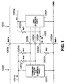
- FIG. 1 shows a portion of the circuit configuration of interface of a note book personal computer 1000 and a battery pack 1002.
- the note book personal computer 1000 and the battery pack 1002 are detachably connected by a connecting portion 1003.
- a battery plus terminal (Batt + terminal) 1003a and a battery minus terminal (Batt - terminal) 1003e are connecting portions for power supply of the note book personal computer 1000 and the battery pack 1002.
- the note book personal computer 1000 can collect respective information of the battery pack 1002 such as charge/discharge current, battery voltage and capacity, etc. through communication line from the battery pack 1002.
- FIG. 1 there is shown communication system of the two wire type of data line and clock line, and data line and clock line of the note book personal computer 1000 and the battery pack 1002 are respectively connected by a data terminal 1003b and a clock terminal 1003c.
- a B-IN terminal 1003d is connecting portion of a detection line 1002e relating to the loading state to the note book personal computer 1000 body of the battery pack 1002.
- Reference numeral 1001a indicates a 5V power supply line of the note book personal computer 1000
- reference numeral 1001f indicates a communication LSI (Large Scale Integrated Circuit) of the note book personal computer 1000
- reference numeral 1001b indicates a pull-up resistor Rn1 (e.g., 4.7 k ⁇ ) of data line
- ad reference numeral 1001c indicates a pull-up resistor Rn2 (e.g., 4.7 k ⁇ ) of clock line.
- Reference numeral 1001d indicates a pull-down resistor Rn3 (e.g., 10 k ⁇ ) for allowing the loading state detection line 1002e of the battery pack 1002 to be at L level.
- Reference numeral 1002a indicates a 5V power supply line of the battery pack 1002
- reference numeral 1002f indicates a CPU (Central Processing Unit) for charge/discharge control of the battery pack 1002, communication with the note book personal computer 1000 and various calculations.
- Reference numeral 1002d indicates a pull-up resistor Rp3 (e.g., 1 M ⁇ ) of the loading state detection line of the battery pack 1002.
- the loading state detection line 1002e is cut off from the pull-down resistor (Rn3) 1001d, and its signal level shifts from L level to H level by the pull-up resistor (Rp3) 1002d.
- the battery pack 1002 is not loaded into the note book personal computer 1000, or in the case where the note book personal computer 1000 is in sleep state even if it is loaded, power supply to a portion of the circuit within the battery pack 1002 is interrupted to reduce current consumption.
- the battery pack 1002 As difference of charge/discharge operation of the battery pack 1002 by loading state, when it is not loaded, the battery pack 1002 inhibits charge/discharge operation, but when it is loaded, it permits charge/discharge operation if the battery pack 1002 is in normal state.
- Detection that the note book personal computer 1000 is in sleep state during loading is carried out by allowing the CPU 1002f of the battery pack 1002 to detect that signal level of the communication line is not changed for a predetermined time or more.
- the battery pack 1002 serves to apply latch of overcurrent protection so that charge/discharge operation is unable. However, in the case where overcurrent is detected, latch of overcurrent protection is released when the battery pack 1002 is taken out from the note book personal computer 1000.
- the loaded battery pack 1002 does not deliver power to the note book personal computer 1000 until it recognizes that the battery pack 1002 has been loaded (chargeable/dischargeable state).
- the battery pack 1002 in the case where the battery pack 1002 is taken out, it does not inhibit charge/discharge operation until it recognizes that it is taken out except for extraordinary state such as overcurrent, overdischarge or overcharge, etc.
- the function to detect electrical loading state with respect to the connecting portion 1003 of the battery pack 1002 is important.
- the connecting portion 1003 between the note book personal computer 1000 and the battery pack 1002 requires five terminals in total of battery plus terminal 1003a, data terminal 1003b, clock terminal 1003c, B-IN terminal 1003d and battery minus terminal 1003e. Accordingly, in the case where the battery pack 1002 is connected by the connecting portion 1003 with respect to the note book personal computer 1000, unless these five terminals are electrically securely connected, it is impossible to well deliver power with respect to the note book personal computer 1000 from the battery pack 1002.
- the number of these terminals of the connecting portion 1003 can be reduced, particularly if the B-IN terminal 1003d can be eliminated, the number of output terminals at the connecting portion 1003 is reduced.
- the battery pack 1002 can be more reliably electrically connected with respect to the note book personal computer 1000, and miniaturization of the connecting portion can be realized and there can result less unsatisfactory terminal contact.
- This invention has been made in view of the above-described problems, and its object is to provide a battery pack, an electronic equipment system and a method of detecting loading of battery pack such that the number of connecting terminals used in electrically connecting the battery pack with respect to the electronic equipment is reduced so that miniaturization can be realized and there can result less unsatisfactory terminal contact.
- this invention is directed to the configuration in which the battery pack is detachably loaded through electric connecting portion to thereby deliver power, wherein the battery pack detects, by using communication line for carrying out transmission/reception of information between the battery pack and the electronic equipment, whether the battery pack is in the state electrically connected to the connecting portion of the electronic equipment or the battery pack is in the state electrically detached from the connecting portion of the electronic equipment.
- the communication line for informing information between the battery pack and the electronic equipment is utilized.
- the battery pack can detect, on the basis of state of signal of this communication line, whether the battery pack is in the state electrically connected to the connecting portion of the electronic equipment or the battery pack is in the state electrically detached from the connecting portion of the electronic equipment.
- the communication line there are mentioned a data line for carrying out transmission/reception of data between the battery pack and the electronic equipment and a clock line supplied with clock from the electronic equipment.
- a data line for carrying out transmission/reception of data between the battery pack and the electronic equipment and a clock line supplied with clock from the electronic equipment.
- FIG. 2 shows, as the embodiment of this invention, an example in which this invention is applied to a note book type personal computer 1 and a battery pack 2.
- a body 105 of this note book personal computer 1 includes a key board 101, a display 102, a slot 103 of card, and a drive 104 for CD-ROM (Read Only Memory utilizing compact disc), etc.
- the battery 2 is detachably loaded into the body 105 through the electric connecting portion 3 so that it can be electrically connected thereto.
- This battery pack 2 serves to deliver power for operation to the note book personal computer 1 and is called battery package.
- kind of the battery e.g., secondary battery, lithium ion secondary battery when an example is taken may be used.
- battery pack 2 secondary battery and other kind of battery, e.g., lithium ion secondary battery, lead storage battery (so called battery of automotive vehicle), Ni-Cd battery (Nickel-Cadmium battery), Ni-hydrogen battery (Nickel-hydrogen battery), Ni-Zn battery (Nickel Zinc storage battery), polymer battery, Zn-air battery (Zinc-air battery), etc. may be employed.
- lead storage battery so called battery of automotive vehicle
- Ni-Cd battery Nickel-Cadmium battery
- Ni-hydrogen battery Nickel-hydrogen battery
- Ni-Zn battery Nickel Zinc storage battery
- polymer battery Zn-air battery (Zinc-air battery), etc.
- Zinc-air battery Zinc-air battery
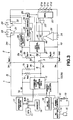
- FIG. 3 shows the state where the battery pack 2 is connected to the note book personal computer 1 through the connecting portion 3 in the embodiment of this invention.
- the note book personal computer 1 shown in FIG. 3 is the system in which only one AC adapter (A.C. power adapter) or the battery pack 2 can be loaded.
- the note book personal computer 1 includes a communication LSI (called communication control unit as occasion may demand (Large Scale Integrated Circuit)) 1f, and two pull-up resistors of a pull-up resistor (Rn1) 1b and a pull-up resistor (Rn2) 1c, etc.
- the communication LSI 1f is connected between, e.g., a power supply line 1a of 5V and a ground line (GND) 10, and respective one end sides of the communication LSI 1f and the two pull-up resistors (Rn1) 1b and (Rn2) 1c are connected to the power supply line 1a of 5V.
- the other end of the pull-up resistor (Rn1) 1b is connected to a data line 3h of the communication LSI 1f, and the other end of the pull-up resistor (Rn2) 1c is connected to a clock line 3i of the communication LSI 1f.
- the data line 3h and the clock line 3i are respectively connected to a data terminal 3b and a clock terminal 3c of the connecting portion 3a.
- Battery lines 3j, 3k of the note book personal computer 1 side are respectively connected to battery plus terminal (Batt + terminal) 3a and battery minus terminal (Batt - terminal) 3e.
- the battery line 3k connected to the battery minus terminal (Batt - terminal) 3e serves as the ground line (GND) 10.
- various peripheral device 17, and memory 18 such as ROM (Read Only Memory) and RAM (Random Access Memory), etc. are connected to bus line BUS of the main CPU (Central Processing Unit), and the communication LSI 1f is connected to this bus line BUS.
- a power switch 13 is provided at a power control circuit 12 so that power ON/OFF control is carried out, and is supplied with commercial A.C. power from a power supply plug 15 through an AC adapter 14 so that power from the battery pack 2 is delivered through the battery lines 3j, 3k.
- charge current supply to the battery pack 2 is carried out through the battery lines 3j, 3k.
- the battery pack 2 includes a CPU (Central Processing Unit) 2f serving as control unit, a single pull-up resistor (Rp11) 2b, and a pull-down resistor (Rp21) 2c. Respective one end sides of the CPU 2f and the pull-up resistor 2b are connected to a power supply line 2a of 5V.
- a data line 3f and a clock line 3g of the CPU 2f can be respectively connected to the data terminal 3b and the clock terminal 3c of the connecting portion 3a.
- the data line 3f is connected to the other end of the pull-up resistor 2b, the clock line 3g is connected to one end of the pull-down resistor 2c, and the other end of the pull-down resistor 2c is connected to the ground line 10.
- a battery cell group composed of, e.g., four battery cells 21a, 21b, 21c and 21d connected in series is accommodated within the battery pack 2.
- the plus side of this battery cell group is connected to the battery plus terminal (Batt + terminal) 3a for external connection through switching element, and the minus side thereof is connected to the battery minus terminal (Batt - terminal) 3e for external connection.
- a multiplexer (MPX) 22 and an operational amplifier 23 In order to measure voltages of respective battery cells 21a, 21b, 21c, 21d of the group of battery cells, there are provided a multiplexer (MPX) 22 and an operational amplifier 23.
- MPX multiplexer
- a battery cell select control signal from the CPU (control unit) 2f is sent to the multiplexer 22 through a control line 44, the multiplexer 22 selects any one of the four battery cells 21a, 21b, 21c, 21d to send its terminal voltage to the operational amplifier 23.
- Output from this operational amplifier 23 is sent to the CPU 2f through a voltage measurement signal line 45, and is caused to undergo A/D (Analog/Digital) conversion within the CPU 2f.
- a resistor 24 for current measurement is inserted and connected at, e.g., the minus side of the battery cell group.
- a voltage corresponding to current value flowing in this resistor 24 is detected by an operational amplifier 25, and is sent to the CPU 2f through a current measurement signal line 46.
- the voltage thus obtained is caused to undergo A/D (Analog/Digital) conversion within the CPU 2f, and current value thus measured is taken as digital value.
- the multiplexer 22 and the operational amplifiers 23, 25 are supplied with power through a power saving switch 26 from the plus side of the battery cell group.
- This switch 26 is subjected to ON/OFF control by power saving control signal delivered through a power saving control line 43 from the CPU 2f.
- a regulator circuit 29 for 5V power supply is connected to the plus side of the battery cell group, and output from the 5V power regulator circuit 29 is delivered to power supply line 2a of 5V.
- a FET 31 serving as switching element for Charge and a FET 32 serving as switching element for Discharge are inserted and connected in series between battery plus terminal (Batt + terminal) 3a of the battery pack 2 and the plus side of the battery cell group, and diodes 33, 34 are respectively connected in parallel with these FETs 31, 32.
- the FET 31 for charge is caused to undergo ON/OFF control by a driver 35.
- This driver 35 is driven by control signal delivered through a charge control line 41 from the CPU 2f.
- the discharge FET 32 is caused to undergo ON/OFF control by a driver 36, and this driver 36 is driven by control signal delivered through a discharge control line 42 from the CPU 2f
- impedance of the 5V power supply line 1a is caused to be high impedance
- data line 3f of the battery pack 2 is pulled up by pull-up resistor 2b (e.g., 1M ⁇ ) so that there results potential on 5V power supply line 2a of the battery pack 2
- clock line is pulled down by pull-down resistor 2c (e.g., 10M ⁇ ) so that there results potential on the ground line 10.
- pull-up resistor 1b of the note book personal computer 1 is caused to be 4.7 k ⁇
- pull-up resistor 1c thereof is caused to be 4.7 k ⁇
- the pull-up resistor 2b of the battery pack 2 is caused to be 1M ⁇
- the pull-down resistor 2c is caused to be 10 M ⁇ .
- This note book personal computer 1 is the system adapted so that only one AC adapter or battery pack can be loaded and 5V power supply line 1a has high impedance.
- the state where the battery pack 2 is electrically detached from the connecting portion 3 and is operative by power supply from the AC adapter 14 is assumed.
- the body 105 of FIG. 2 is in sleep state and data terminal 3b and clock terminal 3c of the communication LSI 1f are held at 5V of the 5V power supply line 1a of high impedance as described above in the state of communication standby.
- Voltage level of the clock line 3g is expressed as 10 M ⁇ x 5/(1M ⁇ + 4.7 k ⁇ + 4.7 k ⁇ + 10M ⁇ )V.
- data line and clock line serving as communication line are used to judge electric insertion or taking-out with respect to the note book personal computer 1 of the battery pack 2, thereby making it possible to reduce the B-IN terminal which was conventionally required serving as detection terminal for insertion or taking-out.
- the 5V power supply line 1a is held at 5V. For this reason, at the time of communication standby, in the case where both signal levels of the data line 3f and the clock line 3g are at H level (5V), when the battery pack 2 is electrically inserted into the connecting portion 3, signal level of the data line 3f is not changed in the state remaining at H level, but signal level of the clock line 3g changes from L level to H level. If this change is detected, the CPU 2f of the battery pack 2 judges that the battery pack 2 has been electrically inserted.
- signal levels of the data line 3f and the clock line 3g of the battery pack 2 are respectively at H level and L level. Accordingly, when it is detected that signal level of the data line 3f is at H level and signal level of the clock line 3g is at L level for a predetermined time or more, the battery pack 2 judges that it is taken out.
- signal levels of the data line 3f and the clock line 3g of the battery pack 2 are respectively caused to be at H level and L level. Accordingly, if signal level of the data line is at H level and signal level of the clock line is at L level for a predetermined time or more, the CPU 2f of the battery pack 2 judges that the battery pack 2 has been taken out.
- signal levels of data line 3f and clock line 3g of the battery pack 2 are respectively caused to be at H level and L level. Accordingly, if it is detected that signal level of data line 3f is at H level and signal level of the clock line 3g is at L level for a predetermined time or more, the CPU 2f of the battery pack 2 judges that the battery pack 2 has been taken out.
- impedance of 5V power supply line 1a of the note book personal computer 1 is caused to be high impedance
- data line 3h of the battery pack 2 is pulled up by pull-up resistor (Rp11) (e.g., 1M ⁇ ) 2b so that potential of 5V power supply line 2a is provided
- the clock line 3g is pulled down by pull-down resistor (Rp21) (e.g., 100 k ⁇ ) 2c so that potential of ground line 10 is provided.
- Resistance value (e.g., 100 k ⁇ ) of this pull-down resistor (Rp21) 2c is value lower as compared to the resistance value (e.g., 10 M ⁇ ) of pull-down resistor Rp21 in the above-described embodiment, and is value which is about one/tenth greater than the resistance value (e.g., 1 M ⁇ ) of the pull-up resistor (Rp11) 2b of the data line 3h.
- impedance of 5V power supply line 1a is caused to correspond to low impedance.
- the battery pack 2 carries out detection of loading states (1), (2), (3) as indicated by the following Table 2.
- STATE OF BATTERY PACK INSERTION (LOADING) TAKING OUT A) STATE (1) COMMUNICATION STANDBY AT TIME OF POWER SUPPLY DATA LINE: H ⁇ H ⁇ H CLOCK LINE: L ⁇ H ⁇ L (B) STATE (2) POWER SUPPLY COMMUNICATING STATE DATA LINE: H ⁇ H/L ⁇ H CLOCK LINE: L ⁇ H/L ⁇ L (C) STATE (3) NO POWER SUPPLY DATA LINE: H ⁇ L ⁇ H CLOCK LINE: L ⁇ L ⁇ L
- This state is the same as the state (1) of (A) of the Table 1.
- the 5V power supply line 1a and the ground line 10 are connected through pull-up resistor 2b, pull-up resistor 1b, pull-up resistor 1c, and pull-down resistor 2c.
- the pull-up resistor 2b is selected so that its resistance value is sufficiently greater than that of the pull-up resistor 1b and the pull-up resistor 1c
- the pull-down resistor 2c is selected so that its resistance value is a value about 1/10 times greater than that of the pull-up resistor 2b.
- signal levels of the data line 3f and the clock line 3g are caused to be at L level.
- Signal level of the clock line 3g is not changed in the state remaining at L level, However, since signal level of the data line changes from H to L, insertion of the battery pack 2 can be judged by this change.
- signal levels of data line 3f and clock line 3g of the battery pack 2 are respectively caused to be at H level and L level. Accordingly, if it is detected that signal level of data line 3f is at H level and signal level of clock line 3g is at L level for a predetermined time or more, the CPU 2f of the battery pack 2 judges that the battery pack 2 has been taken out.
- impedance of 5V power supply line of the note book personal computer is caused to be low impedance (e.g., resistor of 100 k ⁇ is inserted between 5V power supply line and ground line), and impedance of pull-down resistor Rp21 of clock line of the battery pack is caused to be value about 10 times greater than that of the pull-up resistor Rp11 of data line, it is possible to detect loading state by similar operation.
- impedance of 5V power supply line of the note book personal computer is caused to be low impedance (e.g., resistor of 100 k ⁇ is inserted between 5V power supply line and ground line)
- impedance of pull-down resistor Rp21 of clock line of the battery pack is caused to be value about 10 times greater than that of the pull-up resistor Rp11 of data line
- data line 3f of CPU 2f of battery pack 2 is connected to 5V power supply line 2a through pull-up resistor (Rp11) 2b
- clock line 3g is connected to ground line (GND) 10 through pull-down resistor (Rp21).
- data line 3f may be connected to ground line through pull-down resistor
- clock line 3g may be connected to 5V power supply line through pull-up resistor.
- loading detection of the battery pack can be similarly carried out except that the signal state of data line in the Table 1 and the Table 2 and the signal state of clock line are opposite to each other.
- the note book personal computer 1 includes resistor (Rnx) 1h, pull-up resistor (Rn1) 1b, and LSI 1f for communication, etc. Respective one end sides of the communication LSI 1f, the resistor 1h and the pull-up resistor 1b are connected to 5V power supply line 1a, and the other end sides of resistor 1h and communication LSI 1f are connected to the ground line 10 (called battery line 3k as occasion may demand). The other end of the pull-up resistor 1b is connected to data line 3h of communication LSI 1f, and this data line 3h is connected to data terminal 3b. The battery line 3j is connected to the battery terminal 3a, and the ground line 10 (battery line 3k) is connected to the battery terminal 3e.
- resistor (Rnx) 1h Respective one end sides of the communication LSI 1f, the resistor 1h and the pull-up resistor 1b are connected to 5V power supply line 1a, and the other end sides of resistor 1h and communication
- the connecting portion 3 has only three terminals in total of battery terminals 3a, 3e and data terminal 3b.
- the battery pack 2 includes pull-up resistor (Rp11) 2b and CPU 2f, and 5V power supply line 2a is connected to one end portion of the pull-up resistor 2b and one end portion of the CPU 2f.
- the other end of the pull-up resistor 2b is connected to the data line 3f of the CPU 2f.
- the other end of the CPU 2f is connected to the ground line 10.
- the connecting portion 3 includes three terminals 3a to 3e, and the communication LSI 1f and the CPU 2f include only data lines 3h, 3f and have not clock line.
- the electronic equipment of FIG. 4 employs the so-called one wire type communication system, but is different in that the embodiment of FIG. 3 employs so-called two-wire type communication system having data line and clock line.
- resistor Rnx (e.g., 100 k ⁇ ) is inserted between the 5V power supply line 1a and the ground line 10 to allow impedance of 5V power supply line 1a of the note book personal computer 1 to be low impedance, and to pull-up data line 3f of the battery pack 2 by the pull-up resistor (e.g., 1 M ⁇ ) 2b so that potential of the 5V power supply line 2a is provided.
- the battery pack 2 carries out detection of loading state by change of signal level of data line 3f in a manner as shown in the Table 3.
- STATE OF BATTERY PACK INSERTION (LOADING) TAKING OUT A) STATE (1) COMMUNICATION STANDBY AT TIME OF POWER SUPPLY DATA LINE: H ⁇ L ⁇ H (B) STATE (2) POWER SUPPLY COMMUNICATING STATE DATA LINE: H ⁇ H/L ⁇ H (C) STATE (3) NO POWER SUPPLY DATA LINE: H ⁇ L ⁇ H
- the state at the time of the communication standby of the note book personal computer 1 is assumed to be at L level as indicated by (A) of the Table 3.
- signal level of data line 3f of battery pack 2 changes from H level to L level.
- the CPU 2f of the battery pack 2 judges that the battery pack 2 has been inserted.
- signal level of data line 3f of battery pack 2 is caused to be at H level. Accordingly, if the CPU 2f of the battery pack 2 detects that signal level of the data line 3f is caused to be at H level for a predetermined time or more, it judges that the battery pack 2 has been taken out.
- signal level of data line 3f of battery pack 2 is caused to be at H level. Accordingly, if it is detected that signal level of data line 3f is caused to be at H level for a predetermined time or more, the battery pack judges that it has been taken out.
- the battery pack 2 detects loading state to thereby control power supply from the battery pack 2 to the note book personal computer 1, or to carry out charge/discharge control.
- the battery pack 2 is not loaded into the note book personal computer 1 or the note book personal computer 1 is in sleep state even if loaded, power supply to a portion of the circuit within the battery pack 2 is interrupted to reduce current consumption.
- Detection that the note book personal computer 1 is in sleep state during loading is carried out by allowing the CPU 2f of the battery pack 2 to detect that signal level of the communication line is not changed for a predetermined time or more.
- the battery pack 2 applies latch of overcurrent protection so that charge/discharge operation cannot be made, whereby in the case where overcurrent is detected, latch of overcurrent protection is released when it is taken out from the note book personal computer 1.
- the loaded battery pack 2 does not supply power to the note book personal computer 1 until the battery pack 2 is loaded (chargeable/dischargeable state).
- charge/discharge operation is not inhibited until the battery pack 2 recognizes that it has been taken out except for the extraordinary state such as overcurrent, overdischarge or overcharge, etc.
- Control of such charge/discharge operation is carried out by allowing the CPU 2f of the battery pack 2 of FIG. 3 to carry out ON/OFF control of FETs 31, 32 through control lines 41, 42 and through drivers 35, 36.
- the CPU 2f sends a power saving control signal to switch 26 through control line 43 to cut OFF power supply to multiplexer 22 and operational amplifiers 23, 25 to thereby carry out a control such that there results the power saving state.
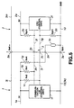
- FIG. 5 is substantially similar to the embodiment of FIG. 3, but a thermistor 30 for temperature compensation is disposed in addition to the embodiment of FIG. 3.
- This thermistor 30 is disposed between 5V power supply line 1a and the ground line 10 of the note book personal computer 1 through resistor 1g and terminal 3n.
- the data line 3f is pulled down with respect to ground 10 through resistor (Rn3) 1g, terminal 3n and thermistor 30.
- resistor (Rn3) 1g, terminal 3n and thermistor 30 When the battery pack 2 is loaded into the note book personal computer 1, signal level of power supply line 1a changes from H level to L level.
- the CPU 2f of the battery pack 2 detects change of signal level (change from H level to L level) of data line 3f, thereby making it possible to detect that the battery pack 2 has been inserted into the note book personal computer 1.
- connection terminals used in electrically connecting the battery pack with respect to the electronic equipment is reduced.
- it is possible to realize miniaturization and avoid unsatisfactory terminal contact.
- B-IN terminal which was conventionally required can be reduced, and miniaturization of the connector by reduction in the number of terminals can be realized and there can result unsatisfactory contact of the terminal.
- note book personal computer While the example of the so-called note book personal computer is mentioned as electronic equipment in the above-described embodiments, this invention is not limited to such implementation.
- This invention is not limited to the note book personal computer, but if equipment to be applied is equipment for which supply of power is required by the battery pack, this invention can be applied to other kind of computers, information terminal, sound recorder, video tape recorder, pocket telephone, electric bicycle and equipments for which the battery pack is required as already described.
Landscapes
- Engineering & Computer Science (AREA)
- Electrochemistry (AREA)
- General Chemical & Material Sciences (AREA)
- Manufacturing & Machinery (AREA)
- Chemical & Material Sciences (AREA)
- Chemical Kinetics & Catalysis (AREA)
- Power Engineering (AREA)
- Theoretical Computer Science (AREA)
- Physics & Mathematics (AREA)
- General Engineering & Computer Science (AREA)
- General Physics & Mathematics (AREA)
- Microelectronics & Electronic Packaging (AREA)
- Power Sources (AREA)
- Battery Mounting, Suspending (AREA)
- Charge And Discharge Circuits For Batteries Or The Like (AREA)
Abstract
Description
| STATE OF BATTERY PACK | INSERTION (LOADING) | TAKING OUT | ||
| (A) | STATE (1) COMMUNICATION STANDBY AT TIME OF POWER SUPPLY | DATA LINE: H → H → H | ||
| CLOCK LINE: L → H → L | ||||
| (B) | STATE (2) POWER SUPPLY COMMUNICATING STATE | DATA LINE: H → H/L → H | ||
| CLOCK LINE: L → H/L → L | ||||
| (C) | STATE (3) NO POWER SUPPLY | DATA LINE: H → H → H | ||
| CLOCK LINE: L → H → L |
| STATE OF BATTERY PACK | INSERTION (LOADING) | TAKING OUT | ||
| (A) | STATE (1) COMMUNICATION STANDBY AT TIME OF POWER SUPPLY | DATA LINE: H → H → H | ||
| CLOCK LINE: L → H → L | ||||
| (B) | STATE (2) POWER SUPPLY COMMUNICATING STATE | DATA LINE: H → H/L → H | ||
| CLOCK LINE: L → H/L → L | ||||
| (C) | STATE (3) NO POWER SUPPLY | DATA LINE: H → L → H | ||
| CLOCK LINE: L → L → L |
| STATE OF BATTERY PACK | INSERTION (LOADING) | TAKING OUT | ||
| (A) | STATE (1) COMMUNICATION STANDBY AT TIME OF POWER SUPPLY | DATA LINE: H → L → H | ||
| (B) | STATE (2) POWER SUPPLY COMMUNICATING STATE | DATA LINE: H → H/L → H | ||
| (C) | STATE (3) NO POWER SUPPLY | DATA LINE: H → L → H |
Claims (21)
- A battery pack adapted to be detachably loaded through an electric connecting portion with respect to an electronic equipment to thereby carry out power supply to the electronic equipment.
wherein a communication line for carrying out transmission/reception of information between the battery pack and the electronic equipment is used to detect whether the battery pack is in the state electrically connected to the connecting portion of the electronic equipment or in the state electrically taken out from the connecting portion of the electronic equipment. - A battery pack as set forth in claim 1,
wherein the communication line is composed of a data line for carrying out transmission/reception of data between the battery pack and the electronic equipment and a clock line supplied with clock from the electronic equipment to detect, on the basis of combination of states of signals on the data line and the clock line, whether the battery pack is in the state electrically connected to the connecting portion of the electronic equipment or in the state electrically detached from the connecting portion of the electronic equipment. - A battery pack as set forth in claim 2,
wherein whether the battery pack is in the state electrically connected to the connecting portion of the electronic equipment or in the state electrically detached from the connecting portion of the electronic equipment is detected in dependency upon presence or absence of a signal on the data line or the clock line when the electronic equipment is supplied with power and communication is being carried out between the battery pack and the electronic equipment. - A battery pack as set forth in claim 2,
wherein whether the battery pack is in the state electrically connected to the connecting portion of the electronic equipment or in the state electrically detached from the connecting portion of the electronic equipment is detected on the basis of change of signal level of the clock line or the data line at the time of a first state where power supply line connected to the data line and the clock line of the electronic equipment is caused to have high impedance, the electronic equipment is supplied with power and communication is not carried out between the battery pack and the electronic equipment, change of signal level of the data line or the clock line at the time of a second state where the electronic equipment is supplied with power and communication is being carried out between the battery pack and the electronic equipment, and change of signal level of the clock line or the data line at the time of a third state where the electronic equipment is not supplied with power. - A battery pack as set forth in claim 2,
wherein whether the battery pack is in the state electrically connected to the connecting portion of the electronic equipment or in the state electrically detached from the connecting portion of the electronic equipment is detected on the basis of change of signal level of the clock line or the data line at the time of a first state where power supply line connected to the data line and the clock line of the electronic equipment is caused to have low impedance, and the electronic equipment is supplied with power and communication is not carried out between the battery pack and the electronic equipment, change of signal level of the data line or the clock line at the time of a second state where the electronic equipment is supplied with power and communication is being carried out between the battery pack and the electronic equipment, and change of signal level of the data line or the clock line at the time of a third state where the electronic equipment is not supplied with power. - A battery pack as set forth in claim 2,
wherein whether the battery pack is in the state electrically connected to the connecting portion of the electronic equipment or in the state electrically detached from the connecting portion of the electronic equipment is detected on the basis of change of signal level of the clock line or the data line at the time of a first state where power supply line of the electronic equipment is caused to have low impedance at the time of loading of the battery pack, and the electronic equipment is supplied with power and communication is not carried out between the battery pack and the electronic equipment, change of signal level of the data line or the clock line at the time of a second state where the electronic equipment is supplied with power and communication is being carried out between the battery pack and the electronic equipment, and change of signal level of the data line or the clock line at the time of a third state where the electronic equipment is not supplied with power. - A battery pack as set forth in claim 1,
wherein the communication line is constituted by data line for carrying out transmission/reception of data between the battery pack and the electronic equipment to detect, on the basis of the state of a signal on the data line, whether the battery pack is in the state electrically connected to the connecting portion of the electronic equipment or in the state electrically detached from the connecting portion of the electronic equipment. - A battery pack as set forth in claim 7,
wherein whether the battery pack is in the state electrically connected to the connecting portion of the electronic equipment or in the state electrically detached from the connecting portion of the electronic equipment is detected in dependency upon presence or absence of a signal on the data line when the electronic equipment is supplied with power and communication is being carried out between the battery pack and the electronic equipment. - A battery pack as set forth in claim 7,
wherein whether the battery pack is in the state electrically connected to the connecting portion of the electronic equipment or in the state electrically detached from the connecting portion of the electronic equipment is detected on the basis of change of signal level of the data line at the time of a first state where the electronic equipment is supplied with power and communication is not carried out between the battery pack and the electronic equipment, change of signal level of the data line at the time of a second state where the electronic equipment is supplied with power and communication is being carried out between the battery pack and the electronic equipment, and change of signal level of the data line at the time of a third state where the electronic equipment is not supplied with power. - An electronic equipment system including a battery pack and an electronic equipment in which the battery pack is detachably loaded through an electric connecting portion so that power supply from the battery pack is carried out,
wherein the battery pack detects, by using a communication line for carrying out transmission/reception of information between the battery pack and the electronic equipment, whether the battery pack is in the state electrically connected to the connecting portion of the electronic equipment or in the state electrically detached from the connecting portion of the electronic equipment. - An electronic equipment system as set forth in claim 10,
wherein the communication line is composed of a data line disposed between the battery pack and the electronic equipment and adapted for carrying out transmission/reception of data, and a clock line disposed between the battery pack and the electronic equipment and supplied with clock therethrough, and the battery pack detects, on the basis of combination of states of signals on the data line and the clock line, whether the battery pack is in the state electrically connected to the connecting portion of the electronic equipment or in the state electrically detached from the connecting portion of the electronic equipment. - An electronic equipment system as set forth in claim 11,
wherein the battery pack detects, in dependency upon presence or absence of a signal on the data line or the clock line when power is supplied from the battery pack to the electronic equipment as the initial state in electrically connecting the battery pack to the electronic equipment and communication is being carried out between the battery pack and the electronic equipment, whether the battery pack is in the state electrically connected to the connecting portion of the electronic equipment or in the state electrically taken out from the connecting portion of the electronic equipment. - An electronic equipment system as set forth in claim 11,
wherein the battery pack detects, on the basis of change of signal level of the clock line or the data line at the time of a first state where the data line and the clock line of the electronic equipment are pulled up to a power supply line placed in the state of high impedance, power is supplied from the battery pack to the electronic equipment as the initial state in electrically connecting the battery pack to the electronic equipment and communication is not carried out between the battery pack and the electronic equipment, presence or absence of a signal on the data line or the clock line at the time of a second state where power is supplied from the battery pack to the electronic equipment and communication is being carried out between the battery pack and the electronic equipment, and change of signal level of the clock line or the data line at the time of a third state where power is not supplied from the battery pack to the electronic equipment, whether the battery pack is in the state electrically connected to the connecting portion of the electronic equipment or in the state electrically detached from the connecting portion of the electronic equipment. - An electronic equipment system as set forth in claim 11,
wherein the battery pack detects, on the basis of change of signal level of the clock line or the data line at the time of a first state where the data line and the clock line of the electronic equipment are pulled up to a power supply line placed in the state of low impedance, and power is supplied from the battery pack to the electronic equipment as the initial state in electrically connecting the battery pack to the electronic equipment and communication is not carried out between the battery pack and the electronic equipment, presence or absence of a signal on the data line or the clock line at the time of a second state where power is supplied from the battery pack to the electronic equipment and communication is being carried out between the battery pack and the electronic equipment, and change of signal level of the data line or the clock line at the time of a third state where power is not supplied from the battery pack to the electronic equipment, whether the battery pack is in the state electrically connected to the connecting portion of the electronic equipment or in the state electrically detached from the connecting portion of the electronic equipment. - An electronic equipment system as set forth in claim 11,
wherein the battery pack detects, on the basis of change of signal level of the clock line or the data line at the time of a first state where power supply line connected to the data line and the clock line of the electronic equipment is caused to have low impedance at the time of loading of the battery pack, and power is supplied from the battery pack to the electronic equipment as the initial state in electrically connecting the battery pack to the electronic equipment and communication is not carried out between the battery pack and the electronic equipment, presence or absence of a signal on the data line or the clock line at the time of a second state where power is supplied from the battery pack to the electronic equipment and communication is being carried out between the battery pack and the electronic equipment, and change of signal level of the data line or the clock line at the time of a third state where power is not supplied from the battery pack to the electronic equipment, whether the battery pack is in the state electrically connected to the connecting portion of the electronic equipment or in the state electrically detached from the connecting portion of the electronic equipment. - An electronic equipment system as set forth in claim 10,
wherein the communication line is disposed between the battery pack and the electronic equipment and comprised of a data line for carrying out transmission/reception of data to detect, on the basis of the state of a signal on the data line, whether the battery pack is in the state electrically connected to the connecting portion of the electronic equipment or in the state electrically detached from the connecting portion of the electronic equipment. - An electronic equipment system as set forth in claim 16,
wherein the battery pack detects, in accordance with presence or absence of a signal on the data line when power is supplied from the battery pack to the electronic equipment as the initial state in electrically connecting the battery pack to the electronic equipment and communication is being carried out between the battery pack and the electronic equipment, whether the battery pack is in the state electrically connected to the connecting portion of the electronic equipment or in the state electrically detached from the connecting portion of the electronic equipment. - An electronic equipment system as set forth in claim 16,
wherein the battery pack detects, on the basis of change of signal level of the data line at the time of a first state where power is supplied from the battery pack to the electronic equipment as the initial state in electrically connecting the battery pack to the electronic equipment and communication is not carried out between the battery pack and the electronic equipment, presence or absence of a signal on the data line at the time of a second state where power is supplied from the battery pack to the electronic equipment and communication is being carried out between the battery pack and the electronic equipment, and change of signal level of the data line at the time of a third state where no power is supplied from the battery pack to the electronic equipment, whether the battery pack is in the state electrically connected to the connecting portion of the electronic equipment or in the state electrically detached from the connecting portion of the electronic equipment. - A loading detection method for battery pack, which is adapted to detachably carry out loading of a battery pack through an electric connecting portion with respect to an electronic equipment to thereby carry out power supply to the electronic equipment,
wherein the battery pack detects, by using a communication line for carrying out transmission/reception of information between the battery pack and the electronic equipment, whether the battery pack is in the state electrically connected to the connecting portion of the electronic equipment, or in the state electrically detached from the connecting portion of the electronic equipment. - A loading detection method for battery pack as set forth in claim 19,
wherein the communication line is composed of a data line for carrying out transmission/reception of data between the battery pack and the electronic equipment and a clock line supplied with clock from the electronic equipment to detect, on the basis of combination of states of signals on the data line and the clock line, whether the battery pack is in the state electrically connected to the connecting portion of the electronic equipment or in the state electrically detached from the connecting portion of the electronic equipment. - A loading detection method for battery pack as set forth in claim 19,
wherein the communication line is comprised of a data line for carrying out transmission/reception of data between the battery pack and the electronic equipment to detect, on the basis of the state of a signal on the data line, whether the battery pack is in the state electrically connected to the connecting portion of the electronic equipment or in the state electrically detached from the connecting portion of the electronic equipment.
Applications Claiming Priority (3)
| Application Number | Priority Date | Filing Date | Title |
|---|---|---|---|
| JP13388797 | 1997-05-23 | ||
| JP133887/97 | 1997-05-23 | ||
| PCT/JP1998/002279 WO1998053516A1 (en) | 1997-05-23 | 1998-05-25 | Battery pack, electronic device system, and method of detecting attachment of battery pack |
Publications (3)
| Publication Number | Publication Date |
|---|---|
| EP0917229A1 true EP0917229A1 (en) | 1999-05-19 |
| EP0917229A4 EP0917229A4 (en) | 2005-03-02 |
| EP0917229B1 EP0917229B1 (en) | 2009-01-14 |
Family
ID=15115426
Family Applications (1)
| Application Number | Title | Priority Date | Filing Date |
|---|---|---|---|
| EP98921791A Expired - Lifetime EP0917229B1 (en) | 1997-05-23 | 1998-05-25 | Electronic device system with battery pack and detection means of battery pack attachment |
Country Status (5)
| Country | Link |
|---|---|
| US (1) | US6087803A (en) |
| EP (1) | EP0917229B1 (en) |
| KR (1) | KR100539035B1 (en) |
| DE (1) | DE69840469D1 (en) |
| WO (1) | WO1998053516A1 (en) |
Cited By (3)
| Publication number | Priority date | Publication date | Assignee | Title |
|---|---|---|---|---|
| CN102956934A (en) * | 2011-08-17 | 2013-03-06 | 比亚迪股份有限公司 | Battery module group |
| CN103814298A (en) * | 2011-04-28 | 2014-05-21 | 佐尔循环公司 | System and method for automatically detecting battery insertion |
| EP3537565A1 (en) * | 2011-04-28 | 2019-09-11 | ZOLL Circulation, Inc. | Battery management system for control of lithium cells |
Families Citing this family (22)
| Publication number | Priority date | Publication date | Assignee | Title |
|---|---|---|---|---|
| FR2811154B1 (en) * | 2000-07-03 | 2002-10-11 | Digiplug | BATTERY CHARGER, ESPECIALLY FOR A MOBILE PHONE |
| TW200413887A (en) * | 2003-01-20 | 2004-08-01 | Htc Corp | Automatic turn-on portable device by detecting a battery condition |
| JP2005321983A (en) * | 2004-05-07 | 2005-11-17 | Sony Corp | Electronic device, battery pack, power control method for electronic device, and program thereof |
| JP5084117B2 (en) * | 2005-08-02 | 2012-11-28 | 三洋電機株式会社 | Pack batteries and electrical equipment |
| US20080141052A1 (en) * | 2006-12-11 | 2008-06-12 | Carl Thelemann | System and method for detecting battery removal |
| KR100819242B1 (en) * | 2007-04-23 | 2008-04-03 | 삼성전자주식회사 | System and method for recognizing external device in portable terminal |
| CN101316042B (en) * | 2007-05-29 | 2012-07-18 | 深圳迈瑞生物医疗电子股份有限公司 | Safety control system for backup battery interface of medical equipment |
| US7755321B2 (en) * | 2008-03-13 | 2010-07-13 | Sony Ericsson Mobile Communications Ab | Method and apparatus for battery removal detection |
| US8525924B2 (en) * | 2008-12-29 | 2013-09-03 | Red.Com, Inc. | Modular motion camera |
| US8525925B2 (en) | 2008-12-29 | 2013-09-03 | Red.Com, Inc. | Modular digital camera |
| US8604748B2 (en) | 2010-04-27 | 2013-12-10 | St-Ericsson Sa | Methods and systems for detecting battery presence |
| KR101413251B1 (en) * | 2010-08-13 | 2014-06-27 | 주식회사 엘지화학 | Apparatus for managing secondary battery |
| KR101182890B1 (en) * | 2010-12-01 | 2012-09-13 | 삼성에스디아이 주식회사 | System for controlling charging of battery pack |
| KR101211875B1 (en) * | 2011-03-11 | 2012-12-18 | 삼성에스디아이 주식회사 | Battery management system and battery pack comprising the same |
| CN107257152B (en) | 2011-04-28 | 2021-04-09 | 佐尔循环公司 | System for updating data, operating parameters and/or software |
| CN103797681B (en) | 2011-04-28 | 2018-05-11 | 佐尔循环公司 | The system and method for tracking and achieving battery performance |
| US9681028B2 (en) | 2013-03-15 | 2017-06-13 | Red.Com, Inc. | Digital camera with wireless connectivity |
| ES2748454T3 (en) | 2014-04-04 | 2020-03-16 | Red Com Llc | Diffusion module for digital camera |
| US9413177B2 (en) * | 2014-11-05 | 2016-08-09 | Motorola Solutions, Inc. | Efficient apparatus and method for inhibiting corrosion with discharge blocking features in a battery |
| JP2019507996A (en) | 2015-12-14 | 2019-03-22 | レッド.コム,エルエルシー | Modular digital camera and mobile phone |
| JP7034560B2 (en) * | 2019-07-11 | 2022-03-14 | 矢崎総業株式会社 | Power supply |
| JP7368981B2 (en) * | 2019-09-02 | 2023-10-25 | キヤノン株式会社 | Battery packs and electronic equipment |
Family Cites Families (8)
| Publication number | Priority date | Publication date | Assignee | Title |
|---|---|---|---|---|
| US5619117A (en) * | 1982-06-07 | 1997-04-08 | Norand Corporation | Battery pack having memory |
| JP3036996B2 (en) * | 1992-10-13 | 2000-04-24 | 三洋電機株式会社 | Battery monitoring system and battery pack |
| US5629604A (en) * | 1992-11-13 | 1997-05-13 | Zenith Data Systems Corporation | Computer power supply system |
| US5870025A (en) * | 1994-04-26 | 1999-02-09 | Canon Kabushiki Kaisha | Power-supply apparatus and its mounting-completion indication method |
| JP3216032B2 (en) * | 1994-04-26 | 2001-10-09 | キヤノン株式会社 | Power supply device, portable device, and method of indicating completion of attachment of these devices |
| JP3372376B2 (en) * | 1994-11-09 | 2003-02-04 | 富士通株式会社 | Power supply circuit and battery device |
| KR0158109B1 (en) * | 1994-12-28 | 1998-12-15 | 김광호 | Charging control method and its circuit of rechargeable battery |
| US5641587A (en) * | 1995-12-15 | 1997-06-24 | Compaq Computer Corporation | Battery pack with a monitoring circuit for a known system |
-
1998
- 1998-05-25 DE DE69840469T patent/DE69840469D1/en not_active Expired - Lifetime
- 1998-05-25 WO PCT/JP1998/002279 patent/WO1998053516A1/en not_active Ceased
- 1998-05-25 KR KR10-1999-7000528A patent/KR100539035B1/en not_active Expired - Lifetime
- 1998-05-25 US US09/230,328 patent/US6087803A/en not_active Expired - Lifetime
- 1998-05-25 EP EP98921791A patent/EP0917229B1/en not_active Expired - Lifetime
Cited By (6)
| Publication number | Priority date | Publication date | Assignee | Title |
|---|---|---|---|---|
| CN103814298A (en) * | 2011-04-28 | 2014-05-21 | 佐尔循环公司 | System and method for automatically detecting battery insertion |
| EP2702419A4 (en) * | 2011-04-28 | 2014-10-22 | Zoll Circulation Inc | SYSTEM AND METHOD FOR AUTOMATIC BATTERY INTRODUCTION DETECTION |
| CN103814298B (en) * | 2011-04-28 | 2017-02-15 | 佐尔循环公司 | System and method for automatically detecting battery insertion |
| EP3537565A1 (en) * | 2011-04-28 | 2019-09-11 | ZOLL Circulation, Inc. | Battery management system for control of lithium cells |
| CN102956934A (en) * | 2011-08-17 | 2013-03-06 | 比亚迪股份有限公司 | Battery module group |
| CN102956934B (en) * | 2011-08-17 | 2015-05-13 | 比亚迪股份有限公司 | Battery module group |
Also Published As
| Publication number | Publication date |
|---|---|
| US6087803A (en) | 2000-07-11 |
| EP0917229A4 (en) | 2005-03-02 |
| EP0917229B1 (en) | 2009-01-14 |
| DE69840469D1 (en) | 2009-03-05 |
| WO1998053516A1 (en) | 1998-11-26 |
| KR20000029499A (en) | 2000-05-25 |
| KR100539035B1 (en) | 2005-12-27 |
Similar Documents
| Publication | Publication Date | Title |
|---|---|---|
| EP0917229A1 (en) | Battery pack, electronic device system, and method of detecting attachment of battery pack | |
| US5963019A (en) | Battery pack with battery protection circuit | |
| US6809649B1 (en) | Method and apparatus for communication between an electronic device and a connected battery | |
| US5399446A (en) | Battery cartridge having a terminal for transferring information therefrom | |
| US5903131A (en) | Battery set structure and charge/discharge control apparatus for lithium-ion battery | |
| US8179099B2 (en) | Battery state monitoring circuit and battery device | |
| US6100670A (en) | Multi-functional battery management module operable in a charging mode and a battery pack mode | |
| EP3588660B1 (en) | Battery pack and power system comprising same | |
| JP3372376B2 (en) | Power supply circuit and battery device | |
| US9069538B2 (en) | Preventing dark current flow in a mobile terminal | |
| GB2242083A (en) | Rechargeable battery pack for hand portable radio telephone | |
| JP2000215919A (en) | Electronic equipment and battery unit | |
| US7605565B2 (en) | Battery pack with protection circuit | |
| EP1096638A1 (en) | Electronic device and method of controlling electronic devices | |
| EP0661769B1 (en) | Improvements in or relating to battery pack arrangement | |
| JP3778709B2 (en) | Battery pack | |
| JP3549402B2 (en) | Battery pack | |
| CN102473973A (en) | Portable device, battery pack, reporting method and reporting program | |
| US6377020B1 (en) | Power supply unit | |
| KR20070087496A (en) | Battery unit and electronics | |
| JPS63110918A (en) | battery powered electronics | |
| JPWO1998053516A1 (en) | Battery pack, electronic device system, and battery pack attachment detection method | |
| CN118646116B (en) | Battery protection circuit, battery protection board, electronic devices and control methods | |
| JPH06237536A (en) | Battery usage system | |
| US20040126627A1 (en) | Chargeable battery for medical diagnostic instruments |
Legal Events
| Date | Code | Title | Description |
|---|---|---|---|
| PUAI | Public reference made under article 153(3) epc to a published international application that has entered the european phase |
Free format text: ORIGINAL CODE: 0009012 |
|
| 17P | Request for examination filed |
Effective date: 19990121 |
|
| AK | Designated contracting states |
Kind code of ref document: A1 Designated state(s): DE FR GB |
|
| A4 | Supplementary search report drawn up and despatched |
Effective date: 20050119 |
|
| 17Q | First examination report despatched |
Effective date: 20071107 |
|
| RTI1 | Title (correction) |
Free format text: ELECTRONIC DEVICE SYSTEM WITH BATTERY PACK AND DETECTION MEANS OF BATTERY PACK ATTACHMENT |
|
| GRAP | Despatch of communication of intention to grant a patent |
Free format text: ORIGINAL CODE: EPIDOSNIGR1 |
|
| GRAS | Grant fee paid |
Free format text: ORIGINAL CODE: EPIDOSNIGR3 |
|
| GRAA | (expected) grant |
Free format text: ORIGINAL CODE: 0009210 |
|
| AK | Designated contracting states |
Kind code of ref document: B1 Designated state(s): DE FR GB |
|
| REG | Reference to a national code |
Ref country code: GB Ref legal event code: FG4D |
|
| REF | Corresponds to: |
Ref document number: 69840469 Country of ref document: DE Date of ref document: 20090305 Kind code of ref document: P |
|
| PLBE | No opposition filed within time limit |
Free format text: ORIGINAL CODE: 0009261 |
|
| STAA | Information on the status of an ep patent application or granted ep patent |
Free format text: STATUS: NO OPPOSITION FILED WITHIN TIME LIMIT |
|
| 26N | No opposition filed |
Effective date: 20091015 |
|
| REG | Reference to a national code |
Ref country code: GB Ref legal event code: 746 Effective date: 20120702 |
|
| REG | Reference to a national code |
Ref country code: DE Ref legal event code: R084 Ref document number: 69840469 Country of ref document: DE Effective date: 20120614 |
|
| PGFP | Annual fee paid to national office [announced via postgrant information from national office to epo] |
Ref country code: GB Payment date: 20140521 Year of fee payment: 17 |
|
| PGFP | Annual fee paid to national office [announced via postgrant information from national office to epo] |
Ref country code: FR Payment date: 20140527 Year of fee payment: 17 |
|
| GBPC | Gb: european patent ceased through non-payment of renewal fee |
Effective date: 20150525 |
|
| REG | Reference to a national code |
Ref country code: FR Ref legal event code: ST Effective date: 20160129 |
|
| PG25 | Lapsed in a contracting state [announced via postgrant information from national office to epo] |
Ref country code: GB Free format text: LAPSE BECAUSE OF NON-PAYMENT OF DUE FEES Effective date: 20150525 |
|
| PG25 | Lapsed in a contracting state [announced via postgrant information from national office to epo] |
Ref country code: FR Free format text: LAPSE BECAUSE OF NON-PAYMENT OF DUE FEES Effective date: 20150601 |
|
| PGFP | Annual fee paid to national office [announced via postgrant information from national office to epo] |
Ref country code: DE Payment date: 20170523 Year of fee payment: 20 |
|
| REG | Reference to a national code |
Ref country code: DE Ref legal event code: R071 Ref document number: 69840469 Country of ref document: DE |