EP0916369B1 - Method and arragement for attaching a filter to a repiratory apparatus - Google Patents
Method and arragement for attaching a filter to a repiratory apparatus Download PDFInfo
- Publication number
- EP0916369B1 EP0916369B1 EP98660114A EP98660114A EP0916369B1 EP 0916369 B1 EP0916369 B1 EP 0916369B1 EP 98660114 A EP98660114 A EP 98660114A EP 98660114 A EP98660114 A EP 98660114A EP 0916369 B1 EP0916369 B1 EP 0916369B1
- Authority
- EP
- European Patent Office
- Prior art keywords
- filter
- cylindrical portion
- attachment boss
- respiratory apparatus
- thread
- Prior art date
- Legal status (The legal status is an assumption and is not a legal conclusion. Google has not performed a legal analysis and makes no representation as to the accuracy of the status listed.)
- Expired - Lifetime
Links
- 238000000034 method Methods 0.000 title claims description 10
- 230000000241 respiratory effect Effects 0.000 claims description 24
- 238000007789 sealing Methods 0.000 claims description 21
- 230000013011 mating Effects 0.000 claims 1
- 239000000428 dust Substances 0.000 description 5
- 238000004519 manufacturing process Methods 0.000 description 5
- 239000000463 material Substances 0.000 description 4
- 239000004743 Polypropylene Substances 0.000 description 3
- 230000001419 dependent effect Effects 0.000 description 3
- 239000013013 elastic material Substances 0.000 description 3
- 230000004048 modification Effects 0.000 description 3
- 238000012986 modification Methods 0.000 description 3
- -1 polypropylene Polymers 0.000 description 3
- 229920001155 polypropylene Polymers 0.000 description 3
- 229920002635 polyurethane Polymers 0.000 description 3
- 239000004814 polyurethane Substances 0.000 description 3
- 238000009825 accumulation Methods 0.000 description 2
- 230000001627 detrimental effect Effects 0.000 description 2
- 229920001971 elastomer Polymers 0.000 description 2
- 239000000126 substance Substances 0.000 description 2
- 238000005266 casting Methods 0.000 description 1
- 230000007423 decrease Effects 0.000 description 1
- 238000001914 filtration Methods 0.000 description 1
- 231100001261 hazardous Toxicity 0.000 description 1
- 239000002245 particle Substances 0.000 description 1
- 239000004033 plastic Substances 0.000 description 1
- 229920003023 plastic Polymers 0.000 description 1
- 230000001681 protective effect Effects 0.000 description 1
- 238000005086 pumping Methods 0.000 description 1
- 239000012858 resilient material Substances 0.000 description 1
- 239000000779 smoke Substances 0.000 description 1
- 239000007779 soft material Substances 0.000 description 1
Images


Classifications
-
- A—HUMAN NECESSITIES
- A62—LIFE-SAVING; FIRE-FIGHTING
- A62B—DEVICES, APPARATUS OR METHODS FOR LIFE-SAVING
- A62B7/00—Respiratory apparatus
- A62B7/10—Respiratory apparatus with filter elements
Definitions
- the invention relates generally to joints between parts in respiratory apparatuses intended for removing detrimental substances from respiratory air.
- the invention relates in particular to the attachment of a filter to the blower part of the respiratory apparatus.
- a modern respiratory apparatus 100 usually has, in accordance with Figure 1 , a face mask 101 intended for being secured over the wearer's face by means of straps and a blower part 102 inside which there is a blower (not shown separately in the figure) which sucks air through a filter or filters 103 and blows the air via a hose 104 to the face mask 101.
- the filters 103 are in general disposable. It is possible to link to a respiratory apparatus filters having different filtering properties according to the environment in which the wearer of the respiratory apparatus will be. Common filter types include, for example, particle filters and smoke gas filters.
- FIG. 2 depicts a cross section of a prior art method for attaching a filter 103 to the blower part 102.
- the filter has a threaded boss 201 the outer surface of which has a male thread 202 according to the DIN 3182 standard.
- the blower part 102 has a recess 203 the inner surface of which has a corresponding female thread 204. At the bottom of the recess 203 there is a step 205 against which there is placed a ring-like rubber seal 206.
- the filter 103 is attached to the blower part 102 by screwing its threaded boss 201 into the recess 203, the rim 207 of the outer end of the threaded boss will press against the rubber seal 206 and will seal the joint between the filter and the blower part.
- the filter always has to be screwed all the way to the bottom of the thread in order for the joint to be tight. If the filter has not been screwed into place properly, the joint between the filter and the blower part will leak, which may be fatal for the wearer.
- the DIN 3182 standard prescribes that the length of the threaded boss of the filter must be such that, when the filter is screwed into place, some of the thread remains visible, in which case the thread tends to collect dirt and dust. If the apparatus is used in an environment in which the dirt and dust contain detrimental substances, the dirt and dust accumulated in the thread may in time be hazardous.
- One object of the present invention is to provide a method and arrangement for attaching the filter so that the tightness of the joint is not dependent on whether or not the filter has been screwed all the way home. It is also an object of the invention to provide for the filter an attachment arrangement which is economical in terms of manufacturing techniques. It is a further object of the invention to provide an arrangement which reduces the accumulation of dirt and dust in the thread of the filter.
- the objects of the invention are achieved by forming a sealing zone on the inner surface of the filter attachment boss.
- the arrangement according to the invention is characterized by the features recited in the characterising part of the independent claim directed to an arrangement.
- the invention also relates to a method which is characterized by the features recited in the characterising part of the independent claim directed to a method.
- a cylindrical portion in that part of the respiratory apparatus to which the filter is attached, and when the filter is being attached this portion pushes inside the threaded boss of the filter.
- That filter part which, according to prior art, is threaded, is referred to below generally as an attachment boss.
- an attachment boss Between the outer surface of the cylindrical portion and the inner surface of the attachment boss of the filter it is possible to form a sealing zone by placing between the surfaces, for example, an O-ring of an elastic material, known per se. The closer the sealing zone thus formed is to the outer end of the cylindrical portion, the less the tightness of the arrangement is sensitive to whether or not the filter has been screwed properly in place.
- the invention does not exclude the possibility of the attachment arrangement also having a prior art seal: double sealing will further improve the safety in use of the product.
- the invention is highly applicable to a modular blower part which has a separate blower module to which it is possible to connect, according to need, suction duct modules of different shapes and sizes, to which modules it is further possible to connect a suitable number of filters.
- a filter is connected by the arrangement according to the invention directly to a cylindrical portion in the blower module.
- the suction duct module may in this case be a simple support part which does not have an actual suction duct but which merely supports the joint between the filter and the blower module.
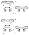
- Figure 3a shows as a partial cross-section a filter 301 and another part 302 of the respiratory apparatus, which part may be, for example the suction duct module of a modular blower part.
- the filter has an attachment boss 303, the outer surface of which has, in this embodiment of the invention, a male thread 304 defined by the DIN 3182 standard, in itself in accordance with prior art.
- the wall of the recess in part 302 has a corresponding female thread 305.
- Part 302 also has a cylindrical portion 306, which is coaxial with thread 305, in which case, when the filter 301 has been screwed into place, the cylindrical portion 306 extends inside the attachment boss 303 of the filter.
- a groove 307 in which there is placed a sealing ring, in itself in accordance with prior art, for example an O-ring 308, made of an elastic material.
- the depth of the groove 307 is smaller than the thickness of the O-ring 308, and thus, when the O-ring 308 is in the groove 307, its outer surface projects somewhat from the outer surface of the cylindrical portion.
- the outer diameter of the cylindrical portion 306 is to such an extent smaller than the inner diameter of the attachment boss 303 of the filter that the cylindrical portion fits well inside the attachment boss; however, the thickness of the O-ring is great enough to cause the inner surface of the attachment boss of the filter to press tightly against the O-ring, whereby a tight joint is formed between the inner surface of the attachment boss 303 and the outer surface of the cylindrical portion 306.
- Figure 3a shows that the tightness of the joint between the filter 301 and the part 302 is not too sensitive to whether or not the filter has been screwed properly in place. If the inner surface of the attachment boss 303 of the filter has substantially the shape of a straight circular cylinder, the filter can be unscrewed (the filter moving upwards relative to the position in the figure) until the outer end of the attachment boss 303 is at the level of the O-ring 308 without the tightness of the joint suffering therefrom. The closer the groove 307 is to the outer end (in the figure, the upwardly pointing end) of the cylindrical portion 306, the further the filter can be unscrewed without the joint beginning to leak.
- Figure 3b shows as a partial cross-section another embodiment of the invention, which is otherwise similar to the embodiment of Figure 3a , but in which there is additionally used a sealing ring 320 in itself in accordance with prior art.
- the inner end (in the figure, the lower end) of the female thread 305 comprised by part 302 has a flat surface 321 against which the sealing ring 320 is placed.
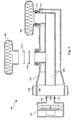
- Figure 4 shows as a partial cross-section a modular blower part 400, which is made up of a blower module 401, a suction duct module 402, and filters 403 and 404.
- the suction duct module 402 is attached to the blower module 401 by the blower module being pushed partly inside the cylindrical connection portion 405 in the suction duct module and by a band 406 being tightened around the connection portion 405 and the blower module portion inside it.
- the connection portion 405, the band 406 and the outer surface of the blower module 401 may have a hole for the hose leading to the face mask of the respiratory apparatus; for the sake of clarity, the hose and the hole are not shown in the figure.
- connection portion 405 it is also possible to form an attachment point for the hose at a point in the blower module which will not come inside the connection portion 405, in which case the connection portion 405 and the band 406 need not have a hole for it.
- the blower module 401 and the suction duct module 402 have been attached to each other, the cylindrical portion 407 in the blower module has been pushed inside the suction duct 408 in the suction duct module.
- the tightness of can, when so desired, be improved by placing in the groove 409 encircling the outer surface of the cylindrical portion 407 an O-ring 410 made of an elastic material.
- the suction duct module 402 has attachment sites for two filters 403 and 404.
- the filter 403 and the seals used for attaching it are shown detached, and the filter 404 and the seals used for attaching it are shown attached.
- the structure of the attachment sites is similar to that in Figure 3b , i.e. each attachment site has a female thread into which the male thread of the attachment boss of the filter fits, and a cylindrical portion which will extend inside the attachment boss of the filter when the filter is screwed in place, an O-ring 411, 412 having been placed in the groove encircling the outer surface of the cylindrical portion.
- the joints between the suction duct module 402 and the filters 403 and 404 are sealed by the O-ring 411, 412 and additionally - when the filters are properly screwed in place - by the prior-art sealing ring 413, 414.
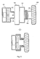
- Figure 5 shows as a partial cross-section the attachment of a filter 403, in the manner according to the invention, directly to the blower module 401.
- the attachment boss 303 of the filter 403 is simply pushed over the cylindrical portion 407 in the blower module 401, whereupon the O-ring 410 placed in the groove 409 encircling the outer surface of the cylindrical portion 407 will seal the joint between the filter and the blower module.
- the purpose of the cylindrical portion 407 is to direct air to the impeller or corresponding pumping means which is in the blower module and which, rotated by an electric motor, pumps the air to the face mask of the respiratory apparatus.
- the arrangement additionally includes a support part 501, which has a female thread 502 fitting the male thread of the attachment boss of the filter, and which can be attached to the blower module 401 by an arrangement based on a tightening band 406, similar to that described above in connection with Figure 4 with reference to the attachment of the suction duct module 402 to the blower part 401.
- FIG. 6 shows how a prior art sealing ring 320 is added to an arrangement in which the filter is directly connected to the blower module.
- the frame material of filters is most commonly injection-molded polypropylene.
- the frame material of the blower module is most commonly fiberglass-reinforced injection-molded polypropylene.
- the suction duct module may be of some more resilient material, such as polyurethane, which has been shaped, for example, by casting. Advantages derived from the selection of the materials are described, for example, in the same applicant's Finnish patent application number 972931 .
- the DIN 3182 standard requires that the thread by which the filter is attached to some other part of the respiratory apparatus meets, among others, certain rigidity requirements.
- the sealing in the attachment of the filter is not dependent on the rigidity of the thread, and thus the use of inserts can, at least in part, be forgone.
- the support part 501 may in its entirety be made of polyurethane. Plastic parts manufactured entirely of the same material are advantageous in terms of both the manufacturing techniques and recyclability.
- the invention does not presuppose that the inner surface of the attachment boss of the filter have the shape of a straight circular cylinder; it may be slightly conical so that the inner diameter of the attachment boss is at its maximum at the outermost end of the attachment boss and decreases towards the inner end of the attachment boss.
- the advantageous features of the invention will be lost, since an attachment boss having a conical inner surface becomes sealed against an O-ring on the surface of the cylindrical portion, coming inside it, in the best possible manner only when the filter has been screwed properly in place.
- the cylindrical portion which, when the filter is being attached, pushes inside the attachment boss of the filter may have a shape other than cylindrical; the invention presupposes only that a sufficiently large proportion of it fits inside the attachment boss of the filter so that the sealing zone can be formed.
- the said cylindrical portion is called cylindrical only so that it would have a certain consistent and unambiguous name.
- the invention does not presuppose that the outer surface of the attachment boss of the filter have a thread according to the DIN 3182 standard, or that the outer surface of the attachment boss have any thread, but since filter manufacturing lines are typically equipped to form a thread on the outer surface of the attachment boss of a filter, it is advantageous in terms of manufacturing techniques that the arrangement according to the invention allows the presence of a thread similar to that in prior art arrangements.
Landscapes
- Health & Medical Sciences (AREA)
- Pulmonology (AREA)
- General Health & Medical Sciences (AREA)
- Business, Economics & Management (AREA)
- Emergency Management (AREA)
- Respiratory Apparatuses And Protective Means (AREA)
- Filtering Of Dispersed Particles In Gases (AREA)
Description
- The invention relates generally to joints between parts in respiratory apparatuses intended for removing detrimental substances from respiratory air. The invention relates in particular to the attachment of a filter to the blower part of the respiratory apparatus.
- A modern
respiratory apparatus 100 usually has, in accordance withFigure 1 , aface mask 101 intended for being secured over the wearer's face by means of straps and ablower part 102 inside which there is a blower (not shown separately in the figure) which sucks air through a filter orfilters 103 and blows the air via ahose 104 to theface mask 101. Thefilters 103 are in general disposable. It is possible to link to a respiratory apparatus filters having different filtering properties according to the environment in which the wearer of the respiratory apparatus will be. Common filter types include, for example, particle filters and smoke gas filters. -
Figure 2 depicts a cross section of a prior art method for attaching afilter 103 to theblower part 102. The filter has a threadedboss 201 the outer surface of which has amale thread 202 according to the DIN 3182 standard. Theblower part 102 has arecess 203 the inner surface of which has a correspondingfemale thread 204. At the bottom of therecess 203 there is astep 205 against which there is placed a ring-like rubber seal 206. When thefilter 103 is attached to theblower part 102 by screwing its threadedboss 201 into therecess 203, therim 207 of the outer end of the threaded boss will press against therubber seal 206 and will seal the joint between the filter and the blower part. - One of the disadvantages of the prior art arrangement is that the filter always has to be screwed all the way to the bottom of the thread in order for the joint to be tight. If the filter has not been screwed into place properly, the joint between the filter and the blower part will leak, which may be fatal for the wearer. On the other hand, the DIN 3182 standard prescribes that the length of the threaded boss of the filter must be such that, when the filter is screwed into place, some of the thread remains visible, in which case the thread tends to collect dirt and dust. If the apparatus is used in an environment in which the dirt and dust contain detrimental substances, the dirt and dust accumulated in the thread may in time be hazardous.
- Prior art publications that disclose features of attaching a filter to a respiratory apparatus are for example
EP 065 754 EP 090 083 EP 394 139 DE 748 953 , andFR 2 537 695 - One object of the present invention is to provide a method and arrangement for attaching the filter so that the tightness of the joint is not dependent on whether or not the filter has been screwed all the way home. It is also an object of the invention to provide for the filter an attachment arrangement which is economical in terms of manufacturing techniques. It is a further object of the invention to provide an arrangement which reduces the accumulation of dirt and dust in the thread of the filter.
- The objects of the invention are achieved by forming a sealing zone on the inner surface of the filter attachment boss.
- The arrangement according to the invention is characterized by the features recited in the characterising part of the independent claim directed to an arrangement.
- The invention also relates to a method which is characterized by the features recited in the characterising part of the independent claim directed to a method.
- According to the invention, it is possible to form a cylindrical portion in that part of the respiratory apparatus to which the filter is attached, and when the filter is being attached this portion pushes inside the threaded boss of the filter. That filter part which, according to prior art, is threaded, is referred to below generally as an attachment boss. Between the outer surface of the cylindrical portion and the inner surface of the attachment boss of the filter it is possible to form a sealing zone by placing between the surfaces, for example, an O-ring of an elastic material, known per se. The closer the sealing zone thus formed is to the outer end of the cylindrical portion, the less the tightness of the arrangement is sensitive to whether or not the filter has been screwed properly in place. The invention does not exclude the possibility of the attachment arrangement also having a prior art seal: double sealing will further improve the safety in use of the product.
- The invention is highly applicable to a modular blower part which has a separate blower module to which it is possible to connect, according to need, suction duct modules of different shapes and sizes, to which modules it is further possible to connect a suitable number of filters. According to one preferred embodiment, a filter is connected by the arrangement according to the invention directly to a cylindrical portion in the blower module. The suction duct module may in this case be a simple support part which does not have an actual suction duct but which merely supports the joint between the filter and the blower module.
- The invention is described below in greater detail with reference to preferred embodiments presented by way of example and to the accompanying figures, wherein
- Figure 1
- depicts a prior art respiratory apparatus,
- Figure 2
- depicts a prior art arrangement for attaching the filter,
- Figure 3a
- depicts the principle of the invention,
- Figure 3b
- depicts a modification of the principle of
Figure 3a , - Figure 4
- depicts the principle according to
Figure 3b applied to one modular blower part, - Figure 5
- depicts the principle according to
Figure 3a applied to another modular blower part, and - Figure 6
- depicts one modification of the invention.
- Above, in connection with the description of prior art, reference was made to
Figures 1 and 2 , and thus below, in the description of the invention, reference will be made primarily toFigures 3a - 6 . In the figures, the same reference numerals are used for parts which correspond one to another. -
Figure 3a shows as a partial cross-section afilter 301 and anotherpart 302 of the respiratory apparatus, which part may be, for example the suction duct module of a modular blower part. The filter has anattachment boss 303, the outer surface of which has, in this embodiment of the invention, amale thread 304 defined by the DIN 3182 standard, in itself in accordance with prior art. The wall of the recess inpart 302 has a correspondingfemale thread 305.Part 302 also has acylindrical portion 306, which is coaxial withthread 305, in which case, when thefilter 301 has been screwed into place, thecylindrical portion 306 extends inside theattachment boss 303 of the filter. Encircling the outer surface of thecylindrical portion 306 there is agroove 307 in which there is placed a sealing ring, in itself in accordance with prior art, for example an O-ring 308, made of an elastic material. The depth of thegroove 307 is smaller than the thickness of the O-ring 308, and thus, when the O-ring 308 is in thegroove 307, its outer surface projects somewhat from the outer surface of the cylindrical portion. The outer diameter of thecylindrical portion 306 is to such an extent smaller than the inner diameter of theattachment boss 303 of the filter that the cylindrical portion fits well inside the attachment boss; however, the thickness of the O-ring is great enough to cause the inner surface of the attachment boss of the filter to press tightly against the O-ring, whereby a tight joint is formed between the inner surface of theattachment boss 303 and the outer surface of thecylindrical portion 306. -
Figure 3a shows that the tightness of the joint between thefilter 301 and thepart 302 is not too sensitive to whether or not the filter has been screwed properly in place. If the inner surface of theattachment boss 303 of the filter has substantially the shape of a straight circular cylinder, the filter can be unscrewed (the filter moving upwards relative to the position in the figure) until the outer end of theattachment boss 303 is at the level of the O-ring 308 without the tightness of the joint suffering therefrom. The closer thegroove 307 is to the outer end (in the figure, the upwardly pointing end) of thecylindrical portion 306, the further the filter can be unscrewed without the joint beginning to leak. -
Figure 3b shows as a partial cross-section another embodiment of the invention, which is otherwise similar to the embodiment ofFigure 3a , but in which there is additionally used asealing ring 320 in itself in accordance with prior art. The inner end (in the figure, the lower end) of thefemale thread 305 comprised bypart 302 has aflat surface 321 against which the sealingring 320 is placed. When thefilter 301 is screwed fully into place, the outermost end of its attachment boss will press against the sealingring 320 in the same manner as in prior art arrangements. Since, however, in the arrangement depicted inFigure 3b there is also a sealing zone according to the invention between the outer surface of thecylindrical portion 306 and the inner surface of theattachment boss 303, a very high safety in use is achieved through this arrangement: when the filter has been screwed properly in place, the joint between it andpart 302 has two sealing zones, and even if the filter were accidentally slightly unscrewed, there would still remain one sealing zone. -
Figure 4 shows as a partial cross-section amodular blower part 400, which is made up of ablower module 401, asuction duct module 402, andfilters suction duct module 402 is attached to theblower module 401 by the blower module being pushed partly inside thecylindrical connection portion 405 in the suction duct module and by aband 406 being tightened around theconnection portion 405 and the blower module portion inside it. Theconnection portion 405, theband 406 and the outer surface of theblower module 401 may have a hole for the hose leading to the face mask of the respiratory apparatus; for the sake of clarity, the hose and the hole are not shown in the figure. On the other hand, it is also possible to form an attachment point for the hose at a point in the blower module which will not come inside theconnection portion 405, in which case theconnection portion 405 and theband 406 need not have a hole for it. When theblower module 401 and thesuction duct module 402 have been attached to each other, thecylindrical portion 407 in the blower module has been pushed inside thesuction duct 408 in the suction duct module. Between the outer surface of thecylindrical portion 407 and the inner surface of thesuction duct 408 there is formed a joint the tightness of which can, when so desired, be improved by placing in thegroove 409 encircling the outer surface of thecylindrical portion 407 an O-ring 410 made of an elastic material. - The
suction duct module 402 has attachment sites for twofilters filter 403 and the seals used for attaching it are shown detached, and thefilter 404 and the seals used for attaching it are shown attached. The structure of the attachment sites is similar to that inFigure 3b , i.e. each attachment site has a female thread into which the male thread of the attachment boss of the filter fits, and a cylindrical portion which will extend inside the attachment boss of the filter when the filter is screwed in place, an O-ring suction duct module 402 and thefilters ring art sealing ring 413, 414. -
Figure 5 shows as a partial cross-section the attachment of afilter 403, in the manner according to the invention, directly to theblower module 401. Theattachment boss 303 of thefilter 403 is simply pushed over thecylindrical portion 407 in theblower module 401, whereupon the O-ring 410 placed in thegroove 409 encircling the outer surface of thecylindrical portion 407 will seal the joint between the filter and the blower module. The purpose of thecylindrical portion 407 is to direct air to the impeller or corresponding pumping means which is in the blower module and which, rotated by an electric motor, pumps the air to the face mask of the respiratory apparatus. The combination between the blower module and the filter, wherein theattachment boss 303 of the filter is pushed over thecylindrical portion 407, would not in itself require any other parts. For the firmness of the joint it is, however, preferable that the arrangement additionally includes asupport part 501, which has afemale thread 502 fitting the male thread of the attachment boss of the filter, and which can be attached to theblower module 401 by an arrangement based on atightening band 406, similar to that described above in connection withFigure 4 with reference to the attachment of thesuction duct module 402 to theblower part 401. It is clear that it would also be possible to add to the arrangement according toFigure 5 a prior art seal, for example by forming at the inner end (in the figure, the left end) of the cylindrical portion of the blower module 401 a flat surface against which the prior art sealing ring would be placed. - Since in the arrangement according to the invention the sealing is not produced at the outermost end of the attachment boss of the filter, and since the tightness of the joint between the filter and the rest of the respiratory apparatus is not dependent on the axial movement of the attachment boss of the filter (movement in the orientation of the central axis of the attachment thread), that part (most preferably the suction duct module or the support part according to
Figure 5 ) of the respiratory apparatus which has a female thread for the attachment of the filter can be shaped in a manner deviating from prior art. Above there was mentioned the prior art DIN 3182 standard, according to which some of the thread of the attachment boss must remain visible even when the filter has been screwed properly into place. In the arrangement according to the invention this need not be so; the filter can be screwed in so far that the entire attachment boss disappears into the recess in the wall of which there is the female thread. - Of the last-mentioned principle there can be presented a modification according to
Figure 6 , in which a separateannular sealing portion 602 is formed in the support part 601 (or some other corresponding part to which the filter is screwed). When thefilter 403 has been screwed fully in place, the sealingportion 602 will press against thatsurface 603 of the filter which faces that respiratory apparatus part to which the filter is attached. An arrangement such as this effectively prevents the accumulation of dirt and dust in the area of the attachment boss of the filter.Figure 6 also shows how a priorart sealing ring 320 is added to an arrangement in which the filter is directly connected to the blower module. - The frame material of filters is most commonly injection-molded polypropylene. In a modular blower unit the frame material of the blower module is most commonly fiberglass-reinforced injection-molded polypropylene. The suction duct module may be of some more resilient material, such as polyurethane, which has been shaped, for example, by casting. Advantages derived from the selection of the materials are described, for example, in the same applicant's Finnish patent application number
972931 Figure 5 , thesupport part 501 may in its entirety be made of polyurethane. Plastic parts manufactured entirely of the same material are advantageous in terms of both the manufacturing techniques and recyclability. - The invention can be modified in various ways without deviating from the protective scope of the patent claims presented below. For example, the invention does not presuppose that the inner surface of the attachment boss of the filter have the shape of a straight circular cylinder; it may be slightly conical so that the inner diameter of the attachment boss is at its maximum at the outermost end of the attachment boss and decreases towards the inner end of the attachment boss. By this there is achieved the advantage that it is easier to guide the filter into its place. On the other hand, at the same time some of the advantageous features of the invention will be lost, since an attachment boss having a conical inner surface becomes sealed against an O-ring on the surface of the cylindrical portion, coming inside it, in the best possible manner only when the filter has been screwed properly in place. Also in the suction duct module or the blower module the cylindrical portion which, when the filter is being attached, pushes inside the attachment boss of the filter may have a shape other than cylindrical; the invention presupposes only that a sufficiently large proportion of it fits inside the attachment boss of the filter so that the sealing zone can be formed. The said cylindrical portion is called cylindrical only so that it would have a certain consistent and unambiguous name. Also, the invention does not presuppose that the outer surface of the attachment boss of the filter have a thread according to the DIN 3182 standard, or that the outer surface of the attachment boss have any thread, but since filter manufacturing lines are typically equipped to form a thread on the outer surface of the attachment boss of a filter, it is advantageous in terms of manufacturing techniques that the arrangement according to the invention allows the presence of a thread similar to that in prior art arrangements.
Claims (5)
- An arrangement for attaching a filter (301, 403, 404) to a respiratory apparatus, the arrangement comprising a respiratory apparatus and a filter, in which arrangement the filter comprises an attachment boss (303) having a threaded outer surface and a smooth inner surface, characterized in that the arrangement comprises:- in that part (302, 402, 401) of the respiratory apparatus to which the filter is to be attached a smooth cylindrical portion (306, 407) having an outer diameter smaller than the inner diameter of the attachment boss,- means (308, 411, 412, 410) for forming a sealing zone between the outer surface of the said cylindrical portion and the inner surface of the said attachment boss,- on the outer surface of the attachment boss of the filter a male thread (304) and- in that part of the respiratory apparatus to which the filter is to be attached a female thread (305) which is concentric with the said cylindrical portion (306) and into which the said male thread fits mechanically.
- An arrangement according to Claim 1, characterized in that- that part of the respiratory apparatus to which the filter is to be attached comprises a blower module and a support part (501, 602) that comprises said female thread (502) into which the said male thread fits mechanically.
- An arrangement according to Claim 2, characterized in that it additionally comprises means for attaching the blower module (401) and the support part (501, 601) to each other in a position in which the said female thread (502) and the said cylindrical portion (407) are located concentrically relative to each other.
- An arrangement according to Claim 1 or 2, characterized in that the said male thread is a thread according to the DIN 3182 standard, such that the length of the threaded boss of the filter must be such that, when the filter is screwed in place, some of the thread remains visible.
- A method for attaching a filter to a respiratory apparatus, characterized in that in the method there is formed a sealing zone (308, 411, 412, 410) between the smooth outer surface of a cylindrical portion (306, 407) in that part (302, 401, 402) of the respiratory apparatus to which the filter is attached and the smooth inner surface of an attachment boss (303) in the filter, said smooth outer surface of said cylindrical portion (306, 407) having an outer diameter smaller than the inner diameter of the attachment boss, and that the attachment between the filter (403) and that part of the respiratory apparatus to which the filter is attached is additionally supported by screwing a male thread (304) on the outer surface of the said attachment boss into a female thread (305) mechanically mating with it.
Applications Claiming Priority (2)
| Application Number | Priority Date | Filing Date | Title |
|---|---|---|---|
| FI974123 | 1997-11-04 | ||
| FI974123A FI117161B (en) | 1997-11-04 | 1997-11-04 | Method and arrangement for attaching a filter to a respirator |
Publications (3)
| Publication Number | Publication Date |
|---|---|
| EP0916369A2 EP0916369A2 (en) | 1999-05-19 |
| EP0916369A3 EP0916369A3 (en) | 2001-05-09 |
| EP0916369B1 true EP0916369B1 (en) | 2012-01-18 |
Family
ID=8549856
Family Applications (1)
| Application Number | Title | Priority Date | Filing Date |
|---|---|---|---|
| EP98660114A Expired - Lifetime EP0916369B1 (en) | 1997-11-04 | 1998-11-04 | Method and arragement for attaching a filter to a repiratory apparatus |
Country Status (2)
| Country | Link |
|---|---|
| EP (1) | EP0916369B1 (en) |
| FI (1) | FI117161B (en) |
Cited By (1)
| Publication number | Priority date | Publication date | Assignee | Title |
|---|---|---|---|---|
| US10105556B2 (en) | 2013-03-15 | 2018-10-23 | Scott Technologies, Inc. | Respirator filter interface |
Families Citing this family (2)
| Publication number | Priority date | Publication date | Assignee | Title |
|---|---|---|---|---|
| ITPS20010028A1 (en) * | 2001-11-15 | 2003-05-15 | Cl Com Advanced Tecnology Srl | FULL FILTER MASK FOR THE PROTECTION OF BIOLOGICAL AGENTS |
| GB2474917B (en) * | 2009-11-02 | 2015-12-23 | Scott Health & Safety Ltd | Improvements to powered air breathing apparatus |
Family Cites Families (5)
| Publication number | Priority date | Publication date | Assignee | Title |
|---|---|---|---|---|
| DE748953C (en) * | 1940-05-17 | 1945-01-10 | Device for the optional connection of filters or oxygen breathing devices to the connection piece of gas protective masks | |
| DE3120475C1 (en) * | 1981-05-21 | 1982-11-11 | Auergesellschaft Gmbh, 1000 Berlin | Plug connection for detachable connection of connection components on respiratory protection devices |
| DE3211907A1 (en) * | 1982-03-31 | 1983-10-20 | Drägerwerk AG, 2400 Lübeck | DEVICE QUICK CONNECTOR FOR RESPIRATORY MASKS |
| FR2537695B1 (en) * | 1982-12-10 | 1987-03-20 | Commeinhes Remco | SNAP-ON CONNECTION AND RESPIRATORY APPARATUS THUS EQUIPPED |
| FR2646089B1 (en) * | 1989-04-21 | 1991-09-27 | Fenzy Sa | INTERMEDIATE CONNECTION FOR BREATHING APPARATUS |
-
1997
- 1997-11-04 FI FI974123A patent/FI117161B/en not_active IP Right Cessation
-
1998
- 1998-11-04 EP EP98660114A patent/EP0916369B1/en not_active Expired - Lifetime
Cited By (1)
| Publication number | Priority date | Publication date | Assignee | Title |
|---|---|---|---|---|
| US10105556B2 (en) | 2013-03-15 | 2018-10-23 | Scott Technologies, Inc. | Respirator filter interface |
Also Published As
| Publication number | Publication date |
|---|---|
| FI974123L (en) | 1999-05-05 |
| FI117161B (en) | 2006-07-14 |
| EP0916369A2 (en) | 1999-05-19 |
| FI974123A0 (en) | 1997-11-04 |
| EP0916369A3 (en) | 2001-05-09 |
Similar Documents
| Publication | Publication Date | Title |
|---|---|---|
| US5022901A (en) | Compression seal canister | |
| US6044842A (en) | Gasketless connecting adapter | |
| US5603792A (en) | Method of making a transducer-protector device for biomedical haemodialysis lines | |
| KR101618382B1 (en) | Multiple bellow-type filter with increased efficiency | |
| EP0736306B1 (en) | Luer-lock fitting for medical infusion/transfusion lines | |
| EP0329659B1 (en) | Cylindrical air filter with lightweight housing and radially directed seal | |
| AU596232B2 (en) | Filter container for an absorption filter and a particle filter, for direct or indirect connection to a protective mask | |
| US6866700B2 (en) | Filter housing assembly for use in oxygen concentrators and other compressors | |
| US5207811A (en) | Air filter sealing groove | |
| US4537426A (en) | Couplings for non-ferrous pipe | |
| GB2346422B (en) | A pipe coupling | |
| EP0787033A4 (en) | Pressure-actuated radial air filter seal | |
| CA2190391A1 (en) | Trocar valve assembly | |
| JPH09508958A (en) | Easily positionable gasket for rising flange | |
| JPS63203579A (en) | Liquid container | |
| US6511290B1 (en) | Blower housing with integral exhaust flange | |
| EP0130441A2 (en) | Pressure measuring system | |
| EP0916369A2 (en) | Method and arragement for attaching a filter to a repiratory apparatus | |
| CA1169766A (en) | Nipple insert | |
| US20060288674A1 (en) | Filter sealing system | |
| US4116474A (en) | Pipe coupling | |
| US5238476A (en) | Filter device, particularly intake air filter device for combustion engines | |
| EP1106232A1 (en) | Air filter with sealing collar in two parts | |
| EP0942167A2 (en) | Air filter failsafe filtered pressure tap | |
| KR200221602Y1 (en) | Connection structure of filter for water purifier |
Legal Events
| Date | Code | Title | Description |
|---|---|---|---|
| PUAI | Public reference made under article 153(3) epc to a published international application that has entered the european phase |
Free format text: ORIGINAL CODE: 0009012 |
|
| AK | Designated contracting states |
Kind code of ref document: A2 Designated state(s): DE GB SE |
|
| AX | Request for extension of the european patent |
Free format text: AL;LT;LV;MK;RO;SI |
|
| PUAL | Search report despatched |
Free format text: ORIGINAL CODE: 0009013 |
|
| AK | Designated contracting states |
Kind code of ref document: A3 Designated state(s): AT BE CH CY DE DK ES FI FR GB GR IE IT LI LU MC NL PT SE |
|
| AX | Request for extension of the european patent |
Free format text: AL;LT;LV;MK;RO;SI |
|
| RIC1 | Information provided on ipc code assigned before grant |
Free format text: 7A 62B 23/02 A |
|
| 17P | Request for examination filed |
Effective date: 20011001 |
|
| AKX | Designation fees paid |
Free format text: DE GB SE |
|
| RAP1 | Party data changed (applicant data changed or rights of an application transferred) |
Owner name: SCOTT HEALTH AND SAFETY OY |
|
| 17Q | First examination report despatched |
Effective date: 20080418 |
|
| GRAP | Despatch of communication of intention to grant a patent |
Free format text: ORIGINAL CODE: EPIDOSNIGR1 |
|
| GRAS | Grant fee paid |
Free format text: ORIGINAL CODE: EPIDOSNIGR3 |
|
| GRAA | (expected) grant |
Free format text: ORIGINAL CODE: 0009210 |
|
| AK | Designated contracting states |
Kind code of ref document: B1 Designated state(s): DE GB SE |
|
| REG | Reference to a national code |
Ref country code: GB Ref legal event code: FG4D |
|
| REG | Reference to a national code |
Ref country code: DE Ref legal event code: R082 Ref document number: 69842572 Country of ref document: DE |
|
| REG | Reference to a national code |
Ref country code: DE Ref legal event code: R096 Ref document number: 69842572 Country of ref document: DE Effective date: 20120315 |
|
| REG | Reference to a national code |
Ref country code: SE Ref legal event code: TRGR |
|
| PLBE | No opposition filed within time limit |
Free format text: ORIGINAL CODE: 0009261 |
|
| STAA | Information on the status of an ep patent application or granted ep patent |
Free format text: STATUS: NO OPPOSITION FILED WITHIN TIME LIMIT |
|
| 26N | No opposition filed |
Effective date: 20121019 |
|
| PGFP | Annual fee paid to national office [announced via postgrant information from national office to epo] |
Ref country code: DE Payment date: 20121128 Year of fee payment: 15 |
|
| REG | Reference to a national code |
Ref country code: DE Ref legal event code: R097 Ref document number: 69842572 Country of ref document: DE Effective date: 20121019 |
|
| PGFP | Annual fee paid to national office [announced via postgrant information from national office to epo] |
Ref country code: GB Payment date: 20121126 Year of fee payment: 15 Ref country code: SE Payment date: 20121126 Year of fee payment: 15 |
|
| REG | Reference to a national code |
Ref country code: SE Ref legal event code: EUG |
|
| GBPC | Gb: european patent ceased through non-payment of renewal fee |
Effective date: 20131104 |
|
| REG | Reference to a national code |
Ref country code: DE Ref legal event code: R119 Ref document number: 69842572 Country of ref document: DE Effective date: 20140603 |
|
| PG25 | Lapsed in a contracting state [announced via postgrant information from national office to epo] |
Ref country code: DE Free format text: LAPSE BECAUSE OF NON-PAYMENT OF DUE FEES Effective date: 20140603 Ref country code: SE Free format text: LAPSE BECAUSE OF NON-PAYMENT OF DUE FEES Effective date: 20131105 |
|
| PG25 | Lapsed in a contracting state [announced via postgrant information from national office to epo] |
Ref country code: GB Free format text: LAPSE BECAUSE OF NON-PAYMENT OF DUE FEES Effective date: 20131104 |