EP0916071B1 - Triangulation-based 3d imaging and processing method and system - Google Patents
Triangulation-based 3d imaging and processing method and system Download PDFInfo
- Publication number
- EP0916071B1 EP0916071B1 EP96931367A EP96931367A EP0916071B1 EP 0916071 B1 EP0916071 B1 EP 0916071B1 EP 96931367 A EP96931367 A EP 96931367A EP 96931367 A EP96931367 A EP 96931367A EP 0916071 B1 EP0916071 B1 EP 0916071B1
- Authority
- EP
- European Patent Office
- Prior art keywords
- height
- data
- transformed
- values
- gray scale
- Prior art date
- Legal status (The legal status is an assumption and is not a legal conclusion. Google has not performed a legal analysis and makes no representation as to the accuracy of the status listed.)
- Expired - Lifetime
Links
- 238000003672 processing method Methods 0.000 title claims description 12
- 238000003384 imaging method Methods 0.000 title description 30
- 238000000034 method Methods 0.000 claims description 36
- 238000012545 processing Methods 0.000 claims description 24
- 230000008569 process Effects 0.000 claims description 5
- 238000005259 measurement Methods 0.000 description 30
- 238000007689 inspection Methods 0.000 description 19
- 229910000679 solder Inorganic materials 0.000 description 16
- 230000003287 optical effect Effects 0.000 description 14
- 230000006870 function Effects 0.000 description 12
- 238000009826 distribution Methods 0.000 description 10
- 238000001914 filtration Methods 0.000 description 10
- 238000001514 detection method Methods 0.000 description 9
- 230000009467 reduction Effects 0.000 description 9
- 230000009466 transformation Effects 0.000 description 9
- 238000012935 Averaging Methods 0.000 description 8
- 238000005286 illumination Methods 0.000 description 8
- 230000009977 dual effect Effects 0.000 description 7
- 230000008901 benefit Effects 0.000 description 6
- 230000007547 defect Effects 0.000 description 6
- 230000000694 effects Effects 0.000 description 5
- 239000000523 sample Substances 0.000 description 5
- 238000004458 analytical method Methods 0.000 description 4
- 238000012986 modification Methods 0.000 description 4
- 230000004048 modification Effects 0.000 description 4
- 238000000844 transformation Methods 0.000 description 4
- 238000013459 approach Methods 0.000 description 3
- 230000000712 assembly Effects 0.000 description 3
- 238000000429 assembly Methods 0.000 description 3
- 230000001419 dependent effect Effects 0.000 description 3
- 238000013461 design Methods 0.000 description 3
- 238000010586 diagram Methods 0.000 description 3
- 230000002349 favourable effect Effects 0.000 description 3
- 230000006872 improvement Effects 0.000 description 3
- 238000012360 testing method Methods 0.000 description 3
- 238000003491 array Methods 0.000 description 2
- 230000005540 biological transmission Effects 0.000 description 2
- 230000006835 compression Effects 0.000 description 2
- 238000007906 compression Methods 0.000 description 2
- 238000005516 engineering process Methods 0.000 description 2
- 239000000463 material Substances 0.000 description 2
- 238000004377 microelectronic Methods 0.000 description 2
- 230000002123 temporal effect Effects 0.000 description 2
- 230000001131 transforming effect Effects 0.000 description 2
- PXFBZOLANLWPMH-UHFFFAOYSA-N 16-Epiaffinine Natural products C1C(C2=CC=CC=C2N2)=C2C(=O)CC2C(=CC)CN(C)C1C2CO PXFBZOLANLWPMH-UHFFFAOYSA-N 0.000 description 1
- 230000009471 action Effects 0.000 description 1
- 230000004075 alteration Effects 0.000 description 1
- 230000003466 anti-cipated effect Effects 0.000 description 1
- 230000015572 biosynthetic process Effects 0.000 description 1
- 239000000919 ceramic Substances 0.000 description 1
- 230000002301 combined effect Effects 0.000 description 1
- 230000001010 compromised effect Effects 0.000 description 1
- 238000012937 correction Methods 0.000 description 1
- 230000002596 correlated effect Effects 0.000 description 1
- 230000000875 corresponding effect Effects 0.000 description 1
- 238000013500 data storage Methods 0.000 description 1
- 238000011496 digital image analysis Methods 0.000 description 1
- 230000008030 elimination Effects 0.000 description 1
- 238000003379 elimination reaction Methods 0.000 description 1
- 230000002708 enhancing effect Effects 0.000 description 1
- 238000009432 framing Methods 0.000 description 1
- 239000011521 glass Substances 0.000 description 1
- 238000010191 image analysis Methods 0.000 description 1
- 238000010348 incorporation Methods 0.000 description 1
- 230000001788 irregular Effects 0.000 description 1
- 230000007246 mechanism Effects 0.000 description 1
- 239000002184 metal Substances 0.000 description 1
- 229910052751 metal Inorganic materials 0.000 description 1
- 150000002739 metals Chemical class 0.000 description 1
- 238000012544 monitoring process Methods 0.000 description 1
- 239000000123 paper Substances 0.000 description 1
- 238000007781 pre-processing Methods 0.000 description 1
- 230000036316 preload Effects 0.000 description 1
- 238000004886 process control Methods 0.000 description 1
- 230000000135 prohibitive effect Effects 0.000 description 1
- 238000005070 sampling Methods 0.000 description 1
- 239000004065 semiconductor Substances 0.000 description 1
- 230000035945 sensitivity Effects 0.000 description 1
- 239000007787 solid Substances 0.000 description 1
- 238000006467 substitution reaction Methods 0.000 description 1
- 230000003746 surface roughness Effects 0.000 description 1
- 239000000725 suspension Substances 0.000 description 1
- 230000001360 synchronised effect Effects 0.000 description 1
- 238000003466 welding Methods 0.000 description 1
Images


Definitions
- This invention relates to machine vision methods and systems and, in particular, to triangulation-based 3D imaging and processing methods and systems.
- 3D imaging techniques have been demonstrated ranging from con-focal microscopes to time-of-flight laser rangefinders, covering applications from microscopic integrated circuit measurements to large field-of-view applications such as mobile robot navigation. Performance specifications for these sensors vary widely, with a figure of merit often determined based upon specific requirements.
- 3D sensors which can potentially satisfy the measurement requirements include confocal microscopes, dynamic focus sensors, triangulation-based probes, and various interferometric devices. Cost effective solutions for process monitoring where specific regions of interest are monitored now exist, but are often limited in measurement speed.
- a three dimensional imager which can meet accuracy requirements and speed requirements has a recognized need in at least the following areas:
- Triangulation provides the most practical method for a high speed-accuracy product. Triangulation is the most effective method for applications where a relatively short working distance is acceptable and where off-axis viewing of three dimensional shape is tolerable (i.e. no narrow, deep holes).
- Figure 1 shows a sketch of a typical triangulation based sensor.
- An incident laser beam 10 strikes an object 12 at a first or a second height 14 and 16, respectively.
- a position sensitive detector or array sensor 18 is provided as well as a receiver optical system 20 for magnification.
- the instantaneous field of view of the sensor 18 is indicated at 22.
- Height and gray scale information are provided on lines 24 from a signal processor 26 to a computer 28 for image processing and analysis.
- IFOV instantaneous field of view
- an incident laser beam 40 penetrates translucent material of an object 42 and propagates outward becoming visible as background light to a first sensor 50 wherein the object 42 blocks light from a scattering center invisible to the second sensor 44.
- a region 43 of the object 42 scattered light is visible to both detectors. The light is scattered from internal scattering materials 43. The average value no longer is a proper height measurement but is erroneously recorded as a very high peak when, in fact, the region is much lower.
- True surface position is indicated at 46 and a truncated (shadowed) spot distribution is indicated at 48.
- the spot distribution is shown at 52.
- scattered light is only visible to the second sensor 50.
- a ray from the scattering center seen by the sensor 50 is indicated at 49.
- Figure 4 shows a case often found on circuit boards where a series of pads 54 are covered with solder paste or, on a finer scale, where leads are connected to the bonding pads in the inner lead bond region of a tab integrated circuit.
- Figure 4 shows first and second laser light scans 51 and 53 and their associated first and second detectors 56 and 58, respectively.
- a line 60 indicates correct detector position and spots on the detectors 56 and 58 represent actual detector position.
- the pads 54 are in close proximity, and the slanted edges lead to multiple reflections from adjacent pads or secondary background illumination as indicated at line 62.
- Lines 64 indicate useful distance information from the point of interest.
- the sensor sees a secondary reflection from the adjacent pad resulting in an erroneous high value, but the noise is not occluded from the sensor 58, so the error cannot cancel with simple averaging.
- simple averaging results in an artifact at the edge manifested as an incorrect high Z value 58 whereas value 56 is correct.
- FIG. 5 Another important example is shown in Figure 5.
- the object has a shiny surface finish and a curved geometric shape, the configuration which is most challenging for any 3D imaging system.
- a specific example is a single solder ball 66 which is an element of a ball grid array (BGA) consisting of hundreds or even thousands of solder deposits per square inch. Dimensions of each solder ball can vary from about ten microns to about .5 mm. With a high density of small diameter features, inspection will only prove useful if the imaging and image analysis system are able to provide measurements indicating deviation of coplanarity (height) and ball diameter measurements at a very rapid rate of speed, perhaps several thousand per second. Examination of three representative scans across the object illustrate challenges in imaging and preprocessing.
- BGA ball grid array
- Scan #1 (not shown in Figure 5).
- the gray scale and height values will be well matched and well within the dynamic range of the sensor.
- the average height value is a good estimate and cancels some asymmetry in the spot distribution.
- the surface orientation is favorable for both sensors 68 and 70.
- the ALC range is extreme, measurement speed may be compromised. If the range of ALC is insufficient and compression of the strong signal does not produce valid data for the sensor 68, then the sensor 70 will also be out of range. If direct laser diode modulation (only one decade range) is incorporated, this situation can easily occur. Hence, the strongest signal may not always be best.
- Scan #3 A third scan down the side of the object shows a most difficult problem.
- the specular surface illuminates what may be a glossy background which, because of the angle of incidence and reflection, produces an intensity reading at the sensor 68 which is, perhaps, orders of magnitude stronger than the signal from the point of interest. In this case, both the height and intensity readings from the sensors 68 and 70 are much different and indicate a severe error condition and low confidence in the data.
- triangulation based probes are available and can be broadly classified as follows: point sensors, line-of-light systems, and laser scanners producing data rates of about 10K points per second, up to 100K points per second, and up to 10M points per second respectively.
- point sensors have been developed with 4 detector systems and 8 detector systems arranged symmetrically about the transmitted point of light.
- the receivers are positioned at the sides square, and in a ring detector arrangement for 8 detector systems.
- Line-of-light systems offer substantial measurement speed advantages over mechanically scanned point detectors, but are limited by the camera readout rate to the 30K points per second range. Multiple lines of light, high speed framing cameras, or smaller arrays which can be read at faster frame rates offer some advantages. Nevertheless, accuracy will often be unacceptable in measurement applications (as opposed to height presence/absence) unless scene dependent errors are reduced. In laser line-of-light or line scan systems, the symmetry which allows for simple averaging of non-occluded detector pairs is absent, restricting the number of detectors to 2 devices, unless successive scans are utilized with rotation of the imaging head or part, or additional cameras and scan lines added for orthogonal viewing.
- the exposure is controlled to balance the power on the detector.
- the U.S. patent to Nakawaga, 4,553,844 shows a scanning/descanning arrangement for inspecting solder.
- the direction orthogonal to the position sensing axis is blocked resulting in an IFOV which is a narrow strip, similar to the Penney and Stern disclosures.
- the position sensing axis is exposed and with the use of only a single detection device the system is limited by phenomena illustrated in Figures 4 and 5. The most severe errors are not compensated.
- the U.S. patent to Amir, 5,048,965 describes a 3D imaging method using a CCD linear array and matched pairs of lights for occlusion avoidance.
- the method has potential for high speed acquisition (approaching video rates) and, with a 4096 linear array, simultaneous wide field coverage. With this method, two images, each with two matched light sources, are required for occlusion avoidance.
- the equivalent function is provided by a pair of encoded light patterns (illumination gradients of opposite sign) which are projected onto the surface and imaged onto the array, one illumination pattern for each single scan of the object.
- the height measurement obtained from a single illumination direction is computed with ratiometric processing (similar to PSD based systems) applied to the two encoded patterns (which are switched between passes).
- ratiometric processing similar to PSD based systems
- a prescribed relationship between the intensity values is used to compute depth as desired from the illumination spatial profiles. Examination of the resulting equation shows the relationship is equivalent to averaging the centroid estimates obtained from the two illumination directions.
- the U.S. patent to Chen et al., 5,118,192 shows a laser based 3D sensor system with internal mechanical means of rotating sensors to achieve favorable viewing conditions of irregular objects.
- the system utilizes multiple laser transmitters and detectors.
- the arrangement is optimized for viewing of objects like solder joints where occlusion and reflection artifacts are similar as illustrated in Figure 5.
- the oblique illumination and viewing arrangement, together with a means of pivoting the sensor, allow a substantial fraction of the sloped sides of the solder joint to be viewed in such a manner that a high signal-to-noise - low spurious reflection condition - is achieved for typical surface orientation and conditions.
- several conditions can be found by ray tracing for which occlusion and refection artifacts will be present within any single image. For demanding high speed applications, the time to acquire and process multiple viewpoints acquired through rotations and articulation is likely not available.
- An object of the present invention is to provide a triangulation-based 3D imaging and processing method and system including filtering and estimation techniques for 3D imaging so to reduce the measurement errors sensed along the depth position sensitive axis of measurement, hence substantially improving the overall performance of high speed, laser scanned systems.
- Another object of the present invention is to provide a triangulation-based 3D imaging and processing method and system which use information about object structure as seen by differences in measured height and gray scale data, and provide a knowledge-based multi-channel signal processing approach which either estimates (through weighted average of multiple sensor data) or filters each 3D data value for maximum contrast depending upon the confidence level of the information.
- Yet another object of the present invention is to provide a triangulation-based 3D imaging and processing method and system which use a high speed laser scanning system to scan or project a single line of laser light and receive light with exactly two detectors, yet produce a much higher overall speed-accuracy figure of merit than slower mechanically scanned point measurement device which use a plurality (2 or more) of detectors or additional detector/transmitter pairs, hence, maximizing potential utilization.
- Yet another object of the present invention is to provide a triangulation-based 3D imaging and processing method and system which operate in real time robustly and independent of special programming requirements (user intervention and placement of window) which could degrade measurement speed, yet allow for sufficient programming and threshold selection so as to optimize filtering and estimation for different imaging and measurement applications.
- Yet another object of the present invention is to provide a triangulation-based 3D imaging and processing method and system which improve the dynamic range by limiting required use of but not excluding real time light modulation devices (direct laser modulation, Acousto-optic, etc.) which are used to compress or otherwise limit signals into electronic range, recognizing that overload in one channel need not be an overload in another, and that the largest of two signals may not be the most desirable.
- real time light modulation devices direct laser modulation, Acousto-optic, etc.
- Yet another object of the present invention is to provide a triangulation-based 3D imaging and processing method and system which, in turn, provides linear and non-linear pointwise filtering methods for defect enhancement and texture analysis to enhance surface microstructure rather than "average out” the detail as done with the prior art.
- Yet still another object of the present invention is to provide a triangulation-based 3D imaging and processing method and system which weight pixels based upon confidence as determined by a relative match of gray scale and height data, and select transforms based upon the relative match.
- Yet a further object of the present invention is to provide a triangulation-based 3D imaging and processing method and system which include a knowledge-based 3D sensor which produces a confidence measure which can be used to determine data validity, or by means of computer control, control of a manipulator so as to provide feedback for'an articulator if so desired.
- a triangulation-based 3D processing method for generating gray scale values and transformed height values.
- the method includes the steps of generating a first pair of data values represented by height data and intensity data obtained from a first direction with respect to an object and generating a second pair of data values represented by height data and intensity data obtained from a second direction with respect to the object.
- the method also includes the steps of controllably and automatically selecting at least one control algorithm adapted to process the height and intensity data and processing the height data from the first and second directions and the intensity data from the first and second directions with the at least one control algorithm to obtain transformed height data.
- the method includes the step of processing the intensity data from the first and second directions to obtain transformed intensity data.
- the method includes the step of transmitting the transformed height and intensity data which are adapted to be processed by an image processing computer.
- the transformed height data represents at least one transformed height value and the transformed intensity data represents at least one transformed gray scale value.
- the method and system of the invention generally relates to three dimensional imaging and measurement using the principle of triangulation, and specifically relates to the use of laser scanning systems for high speed imaging, in which multiple detection systems are incorporated for improved accuracy through reduction of the effects of occlusion and spurious reflections.
- the invention relates to a new and useful filtering and estimation technique for gray scale and height data acquired by a laser scanning or structured light sensor where each point in the scene is viewed by exactly two sensors positioned on either side of the scan line or projected line of light.
- the method allows for reduction or elimination of errors which otherwise limit the achievable figure of merit of laser scanned systems when compared to much slower point laser triangulation systems incorporating additional detectors.
- FIG. 6 a triangulation-based imaging and processing system constructed in accordance with the present invention.
- the system includes a laser transmitter 100 which generally includes laser beam generator and electronic modulation mechanism for laser intensity control, beam deflector for scanning the laser beam or projecting a line of laser light, and optical focusing means to create a plurality of scanned points or a projected line of light across an object 102.
- a laser transmitter 100 which generally includes laser beam generator and electronic modulation mechanism for laser intensity control, beam deflector for scanning the laser beam or projecting a line of laser light, and optical focusing means to create a plurality of scanned points or a projected line of light across an object 102.
- the laser is typically a CLASS III-B laser diode such as the Sharp LT015-MD with wavelength typically in the range of 780 nm - 830 nm and with maximum power below 50 mw.
- Advances in semiconductor laser diode technology may allow for shorter wavelengths (680 nm) which has a primary advantage of alleviating requirements for enclosures and interlocks.
- Real time intensity modulation by an automatic light control 104 is an option for very wide dynamic range imaging, where the directional reflectance varies by more than about 3 decades.
- the modulation of the laser diode may be direct, but reduction by more than about one decade below the rated power produces undesirable spatial and temporal modes which can introduce spatial noise, particularly in diffractive scanning systems, but also in a classical systems using a polygon, galvanometer, or resonant device.
- the preferred means of modulation is with the use of an acousto-optic modulator with a beveled structure optimized for minimal delay such as 50 ns delay.
- the control range offered with such a modulator is much larger than what is achievable with direct laser modulation, exceeding 2 decades of additional range.
- the preferable method is to "ramp up" the light level and monitor the return with auxiliary amplifying detectors.
- the detectors of choice are avalanche photodiodes, preferably devices with 5 mm or larger diameter supplied by Advanced Photonix Corporation and having combined amplifier/detector rise times of 25 ns or less.
- a means of scanning or projecting a laser beam is needed.
- Other means of high speed scanning include polygon laser scanners, resonant devices and hologons which are mechanical defection units that are less desirable.
- projection of lines of light with the use of high speed cameras for faster readout than the typical 15K points per second can be used, but not for quasi-video rate, full field applications.
- the system of the present invention also generally includes first and second substantially identical sensors or receivers 106 and 108 which view off-axis.
- Each of the receivers 106 and 108 includes an optical delivery and focusing system and a detector having a position sensitive axis for determination of height by position detection and triangulation principle and for determination of received laser beam intensity.
- each of the receivers 106 and 108 also includes a high speed amplifying detector (limiter) for laser intensity control, where a small fraction of the received light is split and delivered to the detector which preferably includes an avalanche photodiode and its associated pre-amplifier.
- a best implementation of the previously mentioned intensity control method will be determined by a combination of the received signals from each of the two detectors.
- Figure 5 best illustrates the point where the capability of the detector 70 is sacrificed.
- Laser intensity control for enhancing the electronic dynamic range is not independent of the optical dynamic range and the effects of optical crosstalk resulting from a finite point spread function.
- the automatic light control 104 is electronic and has inputs derived from the amplifying detectors previously mentioned.
- the light control 104 produces an output voltage to control the modulator of the transmitter 100 based upon a predetermined function of both channels, (i.e. set light output such that Max(g1,g2) ⁇ V maximum and Min(g1,g2) > V minimum where V maximum and V minimum correspond to upper and lower useful limits of position sensor dynamic range) so that, whenever possible, neither channel exceeds a predetermined maximum intensity value set by the maximum useful dynamic range of the position detector, but both channels exceed a lower threshold, thereby maintaining a valid data condition.
- each of the receivers 106 and 108 includes signal processing means or circuit which produces a digital height value representing the centroid of the spot intensity distribution on the detector, and to produce digital gray scale from integrated distribution or peak intensity value.
- Each position detector requires a signal processing means for compressing wide dynamic range signals into a somewhat limited (typically 10-12 bits at high speed) A-D converter.
- a switched gain amplifier system is preferred, where each gain (or compression) stage is activated based upon a comparison with a signal threshold. This allows for good linearity, easy calibration, and good stability with temperature.
- DC restoration circuitry is used (sometimes called correlated double sampling) to compensate for offset drift, but more important, to cancel position dependent errors arising from charge storage and leakage from high signal values to lower ones. If the correction is applied to each pixel, substantial reduction in image smear occurs.
- Other means of signal processing include log ratio circuits which simplify the ratiometric processing to a simple subtraction operation.
- the multiple sensor signals After digitization of the gray scale and height information, the multiple sensor signals must be combined in some way to produce a good estimate of the height value at any given point, along with improving gray scale contrast.
- the averaging or summing limit the capability for study of surface texture when the scanned laser spot size is approximately the size of the surface marks, in some cases it is desirable to enhance these features, rather than average.
- conditional decision logic in which to select a series of alternative linear or non-linear transformations based upon the confidence of the sensor data, knowledge of scene reflectance of transmission characteristics, or the overall measurement goal.
- the function accomplished is both a filter and an estimator as illustrated in Figure 6 as a multi-channel filtering and estimation block 110.
- a controller 112 controls selected logic or numeric function via programmed inputs from a host computer 114.
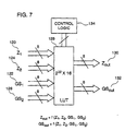
- Figure 7 shows a specific embodiment which provides for implementation of a large number of numerical and combinational logic functions.
- Figure 7 illustrates a general implementation of combining logic for providing filtering and estimation of the 3D (i.e. Z 1 , Z 2 ) and gray scale, GS 1 , GS 2 , information.
- This implementation shows the input and output data to be 8 bits of resolution, however this implementation can apply to any number of bits for the inputs or outputs.
- Inputs 120 (Z 1 ) and 122 (GS 1 ) are the 3D and gray scale information from the first receiver 106
- inputs 124 (Z 2 ) and 126 (GS 2 ) are the 3D and gray scale information from the second receiver 108.
- a look-up table 128 contains enough memory access for a one-to-one correspondence for every input combination to provide a desired output for the Z data 130 and the gray scale data 132.
- This logic can be used to correct various errors that may exist in the system, such as scale and offset errors between the two sensors, or known offsets in the 3D information based upon the gray scale value, as well as provide the proper decision rules to create
- Control logic 134 is used to load the desired decision rule into the look-up table memory, as well as provide quick modifications of the current decision rules based on calibrations, or to select pre-load decision rules with little impact on processing time.
- This general implementation provides full functional encoding of the 3D and gray scale outputs based upon the 3D and gray scale inputs from both receivers. However, at this time, the amount of memory needed may be cost prohibitive for the application it must support. Several variations of this implementation exist that can provide the desired functionality with minimum memory requirements.
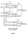
- Figure 8 shows the preferred embodiment with a much smaller memory requirement than the embodiment of Figure 7.
- modification of the gray scale signal need not depend upon the calculated 3D values, therefore a look-up table 140 provides a gray scale output only dependent upon the two gray scale inputs.
- the output of the look-up table 140 can be the result from either receiver only, or a linear or non-linear estimate based upon both channels, such as an average, maximum, or maximum value from each channel.
- Gray scale-to-Z look-up tables 142 and 144 provide full gray scale to 3D transformation for each channel respectively.
- this implementation shows two additional bits which may be used to encode additional information about the gray scale-to-Z relationship, such as gray scale thresholding, which can be passed on to a decision rule look-up table 146. For example, if the first receiver 106 has a gray scale value less than or greater than a pre-set threshold, then the decision rule should select the 3D value from the second receiver 108.
- the number of extra bits passed on from the gray scale-to-Z look-up tables 142 and 144 are shown as two bits, providing up to 4 tests that can be applied in the decision rule look-up table 146. However, any number of bits could be used.
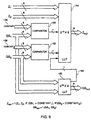
- Figure 9 shows an alternate embodiment with even less of a memory requirement than the embodiment of Figure 8.
- the gray scale-to-Z look-up tables 142 and 144 of Figure 8 are replaced with comparators 150 and 152, which can provide information to a decision rule look-up table 154 after comparing the gray scale data from the first and second receivers 106 and 108 with known constant values on buses 156 and 158.
- This implementation may be preferred if full gray scale-to-3D transformations are not necessary.
- a gray scale-to-gray scale look-up table 160 can also generate an informational bit 162 connected to the decision rule look-up table 154, such as which of the two receivers 106 and 108 is providing the maximum gray scale value.
- this implementation shows one comparator per gray scale channel, multiple comparators could be used to provide multiple threshold data values, including the specifying of a range of gray scale values to select the proper Z decision rule.
- the memory requirement of each of the implementations of Figures 8 and 9 can also be further reduced if the gray scale to gray scale transformation is not needed by replacing the look-up table (140 or 160) with a switch (not shown) to continuously provide the gray scale information from either the first receiver 106 or the second receiver 108.
- the logic providing the gray scale and 3D information may have specifically encoded values in the data that may signify that the gray scale intensity is too high or too low to provide accurate 3D information, or that the 3D information is out of range.
- the transformation tables can pass the special encoded values unchanged to the downstream logic, or even make special decisions based upon the appearance of the special values in one or more channels. Spatial filtering such as a median filter can be used later to "fill-in" the special encoded values based upon the data which can be inferred from the surrounding pixels.
- the combiner of Figure 7 is digital and preprocesses dual channels of 3D and gray scale information or data to provide estimation and filtering of gray scale and 3D data prior to computer image analysis.
- the following typical functions are performed at block 110:
Landscapes
- Length Measuring Devices By Optical Means (AREA)
Description
- Inspection of circuit boards and components: solder paste and components, lead and solder ball grid array coplanarity, package dimensions and lead-to-body standoff;
- Microelectronics assemblies: multi-chip-modules, high density miniature bump grid arrays, TAB inner lead bond, wire bond;
- Micromachined parts: miniature machines and mechanical assemblies;
- Data storage industry: disk platter flatness, disk drive suspensions, defect detection;
- General surface defect detection: ceramics, glass, metals, paper; and
- Shape analysis and matching: forensic science including toolmarks, firearm ID, pattern matching, 3D texture analysis.
Claims (12)
- A triangulation-based 3D processing method for generating gray scale values and transformed height values, the method comprising the steps of:generating a first pair of data values represented by height data and intensity data obtained from a first direction with respect to an object;generating a second pair of data values represented by height data and intensity data obtained from a second direction with respect to the object;controllably and automatically selecting at least one control algorithm adapted to process the height and intensity data; andprocessing the height data from the first and second directions and the intensity data from the first and second directions with the at least one control algorithm to obtain transformed height data.
- The method of claim 1 wherein the transformed height data represents a plurality of transformed height values and wherein an output image comprises a minimum of the transformed height values.
- The method of claim 1 wherein the transformed height data represents a plurality of transformed height values and wherein an output image comprises a maximum of the transformed height values.
- The method of claim 1 wherein the transformed height data represents a difference in transformed height values, the difference being processed by the at least one control algorithm to obtain another transformed height value adapted to be processed by an image processing computer.
- The method of claim 1 further comprising the step of processing the intensity data from the first and second directions to obtain transformed intensity data, the transformed height data representing at least one transformed height value and the transformed intensity data representing at least one transformed gray scale value.
- The method of claim 5 further comprising the step of transmitting the transformed height and intensity data which are adapted to be processed by an image processing computer.
- A triangulation-based 3D processing system for generating gray scale values and transformed height values, the system comprising:means (106) for generating a first pair of data values represented by height data and intensity data obtained from a first direction with respect to an object;means (108) for generating a second pair of data values represented by height data and intensity data obtained from a second direction with respect to the object;means (112) for controllably and automatically selecting at least one control algorithm adapted to process the height and intensity data; andmeans (110) for processing the height data from the first and second directions and the intensity data from the first and second directions with the at least one control algorithm to obtain transformed height data.
- The system of claim 7 wherein the transformed height data represents a plurality of transformed height values and arranged such that an output image comprises a minimum of the transformed height values.
- The system of claim 7 wherein the transformed height data represents a plurality of transformed height values and arranged such that an output image comprises a maximum of the transformed height values.
- The system of claim 7 wherein the transformed height data represents a difference in transformed height values, and arranged such that the difference is being processed by the at least one control algorithm to obtain another transformed height value adapted to be processed by an image processing computer.
- The system of claim 7 further comprising means for processing the intensity data from the first and second directions to obtain transformed intensity data, the transformed height data representing at least one transformed height value and the transformed intensity data representing at least one transformed gray scale value.
- The system of claim 11 further comprising means for transmitting the transformed height and intensity data which are adapted to be processed by an image processing computer.
Applications Claiming Priority (1)
| Application Number | Priority Date | Filing Date | Title |
|---|---|---|---|
| PCT/US1996/012693 WO1998005923A1 (en) | 1994-05-19 | 1996-08-05 | Triangulation-based 3d imaging and processing method and system |
Publications (3)
| Publication Number | Publication Date |
|---|---|
| EP0916071A1 EP0916071A1 (en) | 1999-05-19 |
| EP0916071A4 EP0916071A4 (en) | 2000-12-06 |
| EP0916071B1 true EP0916071B1 (en) | 2003-02-26 |
Family
ID=22255552
Family Applications (1)
| Application Number | Title | Priority Date | Filing Date |
|---|---|---|---|
| EP96931367A Expired - Lifetime EP0916071B1 (en) | 1996-08-05 | 1996-08-05 | Triangulation-based 3d imaging and processing method and system |
Country Status (3)
| Country | Link |
|---|---|
| EP (1) | EP0916071B1 (en) |
| JP (1) | JP2000513099A (en) |
| DE (1) | DE69626424T2 (en) |
Cited By (3)
| Publication number | Priority date | Publication date | Assignee | Title |
|---|---|---|---|---|
| DE102005002190B4 (en) * | 2005-01-17 | 2007-04-12 | Fraunhofer-Gesellschaft zur Förderung der angewandten Forschung e.V. | Scanner and method for operating a scanner |
| US7903245B2 (en) | 2007-08-20 | 2011-03-08 | Marc Miousset | Multi-beam optical probe and system for dimensional measurement |
| TWI495850B (en) * | 2012-03-07 | 2015-08-11 | Kye Systems Corp | Optical sensing device |
Families Citing this family (6)
| Publication number | Priority date | Publication date | Assignee | Title |
|---|---|---|---|---|
| KR101275187B1 (en) | 2011-07-29 | 2013-06-17 | 엘지전자 주식회사 | Panel testing apparatus and method thereof |
| KR101421941B1 (en) * | 2012-09-21 | 2014-07-28 | 주식회사 씨케이앤비 | Apparatus for detecting defect |
| JP6649802B2 (en) * | 2016-02-26 | 2020-02-19 | 株式会社キーエンス | Three-dimensional image inspection device, three-dimensional image inspection method, three-dimensional image inspection program, computer-readable recording medium, and recorded device |
| JP6758062B2 (en) * | 2016-03-22 | 2020-09-23 | 株式会社東洋精機製作所 | Specimen stretch tracking device and tensile test device |
| CN109373931B (en) * | 2018-12-14 | 2020-11-03 | 上海晶电新能源有限公司 | System and method for detecting surface shape of reflecting surface of optical equipment for solar thermal power generation |
| CN111174704B (en) * | 2019-11-26 | 2022-04-19 | 武汉华工激光工程有限责任公司 | Method for measuring height of tin ball by gray image |
Family Cites Families (1)
| Publication number | Priority date | Publication date | Assignee | Title |
|---|---|---|---|---|
| US4687326A (en) * | 1985-11-12 | 1987-08-18 | General Electric Company | Integrated range and luminance camera |
-
1996
- 1996-08-05 JP JP10507868A patent/JP2000513099A/en active Pending
- 1996-08-05 DE DE69626424T patent/DE69626424T2/en not_active Expired - Fee Related
- 1996-08-05 EP EP96931367A patent/EP0916071B1/en not_active Expired - Lifetime
Cited By (3)
| Publication number | Priority date | Publication date | Assignee | Title |
|---|---|---|---|---|
| DE102005002190B4 (en) * | 2005-01-17 | 2007-04-12 | Fraunhofer-Gesellschaft zur Förderung der angewandten Forschung e.V. | Scanner and method for operating a scanner |
| US7903245B2 (en) | 2007-08-20 | 2011-03-08 | Marc Miousset | Multi-beam optical probe and system for dimensional measurement |
| TWI495850B (en) * | 2012-03-07 | 2015-08-11 | Kye Systems Corp | Optical sensing device |
Also Published As
| Publication number | Publication date |
|---|---|
| EP0916071A1 (en) | 1999-05-19 |
| DE69626424D1 (en) | 2003-04-03 |
| DE69626424T2 (en) | 2003-12-24 |
| JP2000513099A (en) | 2000-10-03 |
| EP0916071A4 (en) | 2000-12-06 |
Similar Documents
| Publication | Publication Date | Title |
|---|---|---|
| US5654800A (en) | Triangulation-based 3D imaging and processing method and system | |
| US5812269A (en) | Triangulation-based 3-D imaging and processing method and system | |
| CA1287486C (en) | Method and system for high-speed, high-resolution, 3-d imaging of an object at a vision station | |
| US4796997A (en) | Method and system for high-speed, 3-D imaging of an object at a vision station | |
| US5812268A (en) | Grid array inspection system and method | |
| US6172349B1 (en) | Autofocusing apparatus and method for high resolution microscope system | |
| US6369401B1 (en) | Three-dimensional optical volume measurement for objects to be categorized | |
| US5448359A (en) | Optical distance sensor | |
| EP0417736B1 (en) | System for optically inspecting conditions of parts packaged on substrate | |
| CA2017518A1 (en) | Colour-range imaging | |
| WO1996012981A1 (en) | Autofocusing apparatus and method for high resolution microscope system | |
| CN113474618B (en) | System and method for object inspection using multispectral 3D laser scanning | |
| EP0916071A1 (en) | Triangulation-based 3d imaging and processing method and system | |
| JPH11132748A (en) | Multifocal simultaneous detection device, three-dimensional shape detection device, appearance inspection device, and method thereof | |
| US5880844A (en) | Hybrid confocal microscopy | |
| JP4215220B2 (en) | Surface inspection method and surface inspection apparatus | |
| KR100341637B1 (en) | Triangulation-based 3d imaging and processing method and system | |
| JPH0749930B2 (en) | Mounted board inspection device | |
| GB2204947A (en) | Method and system for high speed, 3-D imaging of an object at a vision station | |
| EP0939294A1 (en) | Determining topographical values | |
| JP2525261B2 (en) | Mounted board visual inspection device | |
| JP2929828B2 (en) | IC lead inspection method and device | |
| JPH02300617A (en) | Shape measuring device | |
| JPH0399208A (en) | Inspection apparatus for mounting board | |
| Jabr | Digitally enhanced micro-interferometry |
Legal Events
| Date | Code | Title | Description |
|---|---|---|---|
| PUAI | Public reference made under article 153(3) epc to a published international application that has entered the european phase |
Free format text: ORIGINAL CODE: 0009012 |
|
| 17P | Request for examination filed |
Effective date: 19990202 |
|
| AK | Designated contracting states |
Kind code of ref document: A1 Designated state(s): DE FI FR GB IE NL SE |
|
| RAP1 | Party data changed (applicant data changed or rights of an application transferred) |
Owner name: GENERAL SCANNING, INC. |
|
| A4 | Supplementary search report drawn up and despatched |
Effective date: 20001023 |
|
| AK | Designated contracting states |
Kind code of ref document: A4 Designated state(s): DE FI FR GB IE NL SE |
|
| 17Q | First examination report despatched |
Effective date: 20010817 |
|
| GRAG | Despatch of communication of intention to grant |
Free format text: ORIGINAL CODE: EPIDOS AGRA |
|
| GRAG | Despatch of communication of intention to grant |
Free format text: ORIGINAL CODE: EPIDOS AGRA |
|
| GRAH | Despatch of communication of intention to grant a patent |
Free format text: ORIGINAL CODE: EPIDOS IGRA |
|
| GRAH | Despatch of communication of intention to grant a patent |
Free format text: ORIGINAL CODE: EPIDOS IGRA |
|
| GRAA | (expected) grant |
Free format text: ORIGINAL CODE: 0009210 |
|
| AK | Designated contracting states |
Designated state(s): DE FI FR GB IE NL SE |
|
| PG25 | Lapsed in a contracting state [announced via postgrant information from national office to epo] |
Ref country code: NL Free format text: LAPSE BECAUSE OF FAILURE TO SUBMIT A TRANSLATION OF THE DESCRIPTION OR TO PAY THE FEE WITHIN THE PRESCRIBED TIME-LIMIT Effective date: 20030226 Ref country code: FI Free format text: LAPSE BECAUSE OF FAILURE TO SUBMIT A TRANSLATION OF THE DESCRIPTION OR TO PAY THE FEE WITHIN THE PRESCRIBED TIME-LIMIT Effective date: 20030226 |
|
| REG | Reference to a national code |
Ref country code: GB Ref legal event code: FG4D |
|
| REG | Reference to a national code |
Ref country code: IE Ref legal event code: FG4D |
|
| REF | Corresponds to: |
Ref document number: 69626424 Country of ref document: DE Date of ref document: 20030403 Kind code of ref document: P |
|
| PG25 | Lapsed in a contracting state [announced via postgrant information from national office to epo] |
Ref country code: SE Free format text: LAPSE BECAUSE OF FAILURE TO SUBMIT A TRANSLATION OF THE DESCRIPTION OR TO PAY THE FEE WITHIN THE PRESCRIBED TIME-LIMIT Effective date: 20030526 |
|
| NLV1 | Nl: lapsed or annulled due to failure to fulfill the requirements of art. 29p and 29m of the patents act | ||
| PG25 | Lapsed in a contracting state [announced via postgrant information from national office to epo] |
Ref country code: IE Free format text: LAPSE BECAUSE OF NON-PAYMENT OF DUE FEES Effective date: 20030805 |
|
| ET | Fr: translation filed | ||
| PLBE | No opposition filed within time limit |
Free format text: ORIGINAL CODE: 0009261 |
|
| STAA | Information on the status of an ep patent application or granted ep patent |
Free format text: STATUS: NO OPPOSITION FILED WITHIN TIME LIMIT |
|
| 26N | No opposition filed |
Effective date: 20031127 |
|
| REG | Reference to a national code |
Ref country code: IE Ref legal event code: MM4A |
|
| PGFP | Annual fee paid to national office [announced via postgrant information from national office to epo] |
Ref country code: FR Payment date: 20040819 Year of fee payment: 9 |
|
| PG25 | Lapsed in a contracting state [announced via postgrant information from national office to epo] |
Ref country code: FR Free format text: LAPSE BECAUSE OF NON-PAYMENT OF DUE FEES Effective date: 20060428 |
|
| REG | Reference to a national code |
Ref country code: FR Ref legal event code: ST Effective date: 20060428 |
|
| PGFP | Annual fee paid to national office [announced via postgrant information from national office to epo] |
Ref country code: GB Payment date: 20070830 Year of fee payment: 12 |
|
| PGFP | Annual fee paid to national office [announced via postgrant information from national office to epo] |
Ref country code: DE Payment date: 20071001 Year of fee payment: 12 |
|
| GBPC | Gb: european patent ceased through non-payment of renewal fee |
Effective date: 20080805 |
|
| PG25 | Lapsed in a contracting state [announced via postgrant information from national office to epo] |
Ref country code: DE Free format text: LAPSE BECAUSE OF NON-PAYMENT OF DUE FEES Effective date: 20090303 |
|
| PG25 | Lapsed in a contracting state [announced via postgrant information from national office to epo] |
Ref country code: GB Free format text: LAPSE BECAUSE OF NON-PAYMENT OF DUE FEES Effective date: 20080805 |