EP0915252A2 - Common rail fuel injection system - Google Patents
Common rail fuel injection system Download PDFInfo
- Publication number
- EP0915252A2 EP0915252A2 EP98117887A EP98117887A EP0915252A2 EP 0915252 A2 EP0915252 A2 EP 0915252A2 EP 98117887 A EP98117887 A EP 98117887A EP 98117887 A EP98117887 A EP 98117887A EP 0915252 A2 EP0915252 A2 EP 0915252A2
- Authority
- EP
- European Patent Office
- Prior art keywords
- rail
- housing
- injection system
- injectors
- openings
- Prior art date
- Legal status (The legal status is an assumption and is not a legal conclusion. Google has not performed a legal analysis and makes no representation as to the accuracy of the status listed.)
- Withdrawn
Links
Images

Classifications
-
- F—MECHANICAL ENGINEERING; LIGHTING; HEATING; WEAPONS; BLASTING
- F02—COMBUSTION ENGINES; HOT-GAS OR COMBUSTION-PRODUCT ENGINE PLANTS
- F02M—SUPPLYING COMBUSTION ENGINES IN GENERAL WITH COMBUSTIBLE MIXTURES OR CONSTITUENTS THEREOF
- F02M39/00—Arrangements of fuel-injection apparatus with respect to engines; Pump drives adapted to such arrangements
- F02M39/02—Arrangements of fuel-injection apparatus to facilitate the driving of pumps; Arrangements of fuel-injection pumps; Pump drives
-
- F—MECHANICAL ENGINEERING; LIGHTING; HEATING; WEAPONS; BLASTING
- F02—COMBUSTION ENGINES; HOT-GAS OR COMBUSTION-PRODUCT ENGINE PLANTS
- F02M—SUPPLYING COMBUSTION ENGINES IN GENERAL WITH COMBUSTIBLE MIXTURES OR CONSTITUENTS THEREOF
- F02M55/00—Fuel-injection apparatus characterised by their fuel conduits or their venting means; Arrangements of conduits between fuel tank and pump F02M37/00
- F02M55/02—Conduits between injection pumps and injectors, e.g. conduits between pump and common-rail or conduits between common-rail and injectors
- F02M55/025—Common rails
-
- F—MECHANICAL ENGINEERING; LIGHTING; HEATING; WEAPONS; BLASTING
- F02—COMBUSTION ENGINES; HOT-GAS OR COMBUSTION-PRODUCT ENGINE PLANTS
- F02M—SUPPLYING COMBUSTION ENGINES IN GENERAL WITH COMBUSTIBLE MIXTURES OR CONSTITUENTS THEREOF
- F02M61/00—Fuel-injectors not provided for in groups F02M39/00 - F02M57/00 or F02M67/00
- F02M61/14—Arrangements of injectors with respect to engines; Mounting of injectors
-
- F—MECHANICAL ENGINEERING; LIGHTING; HEATING; WEAPONS; BLASTING
- F02—COMBUSTION ENGINES; HOT-GAS OR COMBUSTION-PRODUCT ENGINE PLANTS
- F02M—SUPPLYING COMBUSTION ENGINES IN GENERAL WITH COMBUSTIBLE MIXTURES OR CONSTITUENTS THEREOF
- F02M63/00—Other fuel-injection apparatus having pertinent characteristics not provided for in groups F02M39/00 - F02M57/00 or F02M67/00; Details, component parts, or accessories of fuel-injection apparatus, not provided for in, or of interest apart from, the apparatus of groups F02M39/00 - F02M61/00 or F02M67/00; Combination of fuel pump with other devices, e.g. lubricating oil pump
- F02M63/02—Fuel-injection apparatus having several injectors fed by a common pumping element, or having several pumping elements feeding a common injector; Fuel-injection apparatus having provisions for cutting-out pumps, pumping elements, or injectors; Fuel-injection apparatus having provisions for variably interconnecting pumping elements and injectors alternatively
- F02M63/0225—Fuel-injection apparatus having a common rail feeding several injectors ; Means for varying pressure in common rails; Pumps feeding common rails
-
- F—MECHANICAL ENGINEERING; LIGHTING; HEATING; WEAPONS; BLASTING
- F02—COMBUSTION ENGINES; HOT-GAS OR COMBUSTION-PRODUCT ENGINE PLANTS
- F02B—INTERNAL-COMBUSTION PISTON ENGINES; COMBUSTION ENGINES IN GENERAL
- F02B3/00—Engines characterised by air compression and subsequent fuel addition
- F02B3/06—Engines characterised by air compression and subsequent fuel addition with compression ignition
Definitions
- the invention relates to a common rail injection system for internal combustion engines.
- Common rail injection systems are used in internal combustion engines, where the combustion medium is used to optimize the combustion performance in the combustion chambers of the individual cylinders should be atomized.
- the combustion medium is in a High pressure pump compressed and on a rail on the injectors of the individual cylinder distributed.
- the electrical signal is transmitted Injection process of the combustion medium into the combustion chamber triggered, with the combustion medium under high pressure through the injectors of the injectors at high speed finely distributed in the combustion chambers of the engine.
- a pump housing High pressure pump is a flange on a motor housing Internal combustion engine attached.
- the high pressure pump works with one Plunger cylinder which, together with a plunger, creates a delivery chamber limited.
- the delivery chamber is with a line for the inflow of the pressure medium connected, which is regulated by a pressure-controlled inlet valve and the plunger cylinder has a passage for the outflow of the pressure medium, which is also controlled by a pressure-controlled valve is regulated on.
- the plunger cylinder is surrounded by a pressure body, whose flow channels follow the passage opening of the plunger cylinder connect outside.
- JP-A-09 060562 discloses an internal combustion engine with direct injection, where a high pressure fuel pump with the cylinder head connected is.
- the cylinder head has a channel inside through which the fuel is pumped away from the high pressure fuel pump becomes.
- the common rail placed on the injection valves is included connected to the cylinder head and has a passage in its interior to distribute the fuel to the injectors.
- a pump housing is created from a plunger cylinder and a piston guide formed for a high pressure pump. This from plunger cylinder and Existing pump housing engages in a suitable piston guide Opening a motor housing in the way that part of the pump housing protrudes from the motor housing and directly on this by means of bolts is attached.
- This construction is also in construction and assembly complex.
- the present invention has set itself the task of a common rail To provide an improved injection system and before has a simpler structure.
- the injection system is connected to a high pressure pump elongated rail, which has a pressure chamber along its longitudinal axis. Openings for direct reception penetrate the pressure chamber provided by injectors.
- the advantage of such a construction is that the injectors can be inserted directly into the rail, which makes assembly very easy. This brings a further simplification Insert a plunger cylinder in a designated opening of the rail. If the plunger cylinder has a press fit in the Fixing opening of the rail fixed, this affects in the same way and Way out as the encirclement by a pressure body, which in the older CH patent application No. 1997 1275/97.
- various advantages such as the load on the high pressure pump higher pressures can be achieved.
- the injectors used have in the area that after insertion at the pressure chamber of the Rails lies on inlet openings through which the pressure medium enters the injectors flow and are sprayed from there into the combustion chambers can.
- the advantage is that the pressure medium from the pressure chamber of the rail can flow directly into the injectors. The assembly will thereby very simplified and by eliminating the connecting parts material costs can be saved.
- the openings for the injectors in the rail are with their opening axes aligned parallel to each other and are preferably in one plane. This will make the openings for the injectors both in the Rail as well as in the cylinder head housing and inserting the injectors in the openings simplified. This is especially for series production in the Industry of great importance.
- the parallel axis guidance of the receiving opening for the plunger cylinder and the openings for the injectors in turn simplify insertion of the openings and assembly of the entire system. Also made possible this is a straightforward design of the rail.
- the injection system can be further simplified if the rail connects one Forms part of the pump housing, especially if it integrally with the Pump housing or the housing cover is molded.
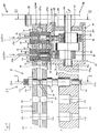
- Internal combustion engine 10 shows an elongated, straight rail 12, the parallel to a cylinder head housing belonging to the internal combustion engine 10 14 is arranged, and a high pressure pump 16 thereof Drive in a known, later described manner from Internal combustion engine 10 takes place.
- the rail has a pressure chamber 20 and along its longitudinal axis 18 perpendicular to it, piercing the rail 12 in the area of the pressure chamber 20, Openings 22 for receiving injectors 24.
- the Openings 22 are parallel to one another with their opening axes 26 arranged and lie in one plane. In their extension, the Opening axes 26 also the axes of injector openings 28 of the Cylinder head housing 14.
- the injectors 24, when they pass through the openings 22 of the rail 12 into the injector openings 28 of the cylinder head housing 14 are used with their injector axes 26a parallel to one another and in one plane.
- the injectors 24 essentially have are rotationally symmetrical, at one end injection nozzles 30 on.
- the injectors 24 are shaped such that the injection nozzles 30 after installation in a combustion chamber 32 shown in FIG. 2 of the internal combustion engine 10 protrude.
- One of the injector 30 opposite injector head 34 protrudes beyond the rail 12.
- the injectors 24 in the section after the Insert the injectors 24 at the level of the pressure chamber 20 of the rail 12 lies, a circumferential groove 36 through which it is ensured that the Injectors 24 flow around the pressure medium located in the pressure chamber 20 can be.
- This section of the injectors 24 are also located Inlet openings 38 through which the pressure medium enters the injectors 24 can flow in.
- a fastener 40 for example a screw connection
- the injectors 24 are fixed in the rail 12.
- the rail 12 On the side of the high pressure pump 16, the rail 12 has two receiving openings 44 for receiving plunger cylinders 46 and one Channel 20a on.
- the channel 20a goes in the dashed line 48 in the Pressure chamber 20 of the rail 12 and connects the receiving openings 44 with the pressure chamber 20 of the rail 12. So that the pressure medium used Plunger cylinders 46 can flow around the channel 20a circumferential grooves embedded in the plunger cylinder 46, which at used plunger cylinders 46 an annular channel 50 (indicated by dashed lines) form around the plunger cylinders 46.
- the plunger cylinders 46 are over a press fit in the rail 12 fixes what the same effect as that Enclose the plunger cylinder with a pressure body, as in the older one CH Patent Application No. 1997 1275/97.
- the receiving openings 44 made in the rail 12 for the plunger cylinders 46 have axes 52 lying parallel to one another, which in one Plane with and parallel to the opening axes 26 of the openings 22 in the Rail 12 or the injector axes 26a of the injectors 24 are arranged. This leads to the fact that the plunger cylinders 46 after their insertion in the receiving openings 44 with their plunger axes 52a parallel and in lie on a plane to the opening axes 26 and the injector axes 26a.
- Each plunger cylinder 46 defines together with a plunger 54 a delivery space 56.
- This delivery space 56 is in the plunger cylinder 46 let inlet channel 58 and a feed line 58a with a reservoir for the pressure medium, not shown.
- the pressure medium is fed in through a pressure-controlled inlet valve 60 regulated.
- the high pressure pump 16 has a pump housing 66, to which below another includes a housing element 68 with a side wall 68a in which Housing openings 70 are excluded.
- the plunger cylinders 46 protrude now with the side in which the plungers 54 in the plunger cylinders 46 are guided into these housing openings 70 of the side wall 68a of the housing element 68 in.
- the housing openings 70 are so designed that between the plunger cylinders 46 and the Housing element 68 remains a small gap 72, so that the plunger cylinders 46 can be inserted into the housing element 68 with some play.
- the housing element 68 is above the side wall 68a via the columns 72 open to the outside. Through the rail 12, which on the side wall 68a of the Housing element 68 is arranged close to the housing element 68 as if closed by a lid.
- Housing element 68 is formed on the inside as a bearing Recess 76 incorporated in which the drive shaft 78 with the Power transmission opposite end region 78a is mounted.
- the wall 74 at the dashed dividing line 74a goes into the integrally molded cylinder head housing 14 on.
- the wall 74 of the housing element 68 closes a side plate 80 which also belongs to the pump housing 66, a further opening of the housing element 68.
- a bearing opening 82 of this side plate 80 is the Drive shaft 78 on its side facing the power transmission stored. In the case of repairs, access is also via this side plate 80 allows the inside of the pump housing 66.
- the plunger cylinders 46 with the plungers 54 and the drive shaft 78 the high pressure pump 16 are arranged at right angles to each other.
- For the Stroke movement of - by means of compression springs 83 in the direction against Drive shaft 78 pushed - plunger 54 in the plunger cylinders 46 of the high pressure pump 16 are on the drive shaft 78 of the high pressure pump 16 eccentric 84 attached.
- Between the eccentrics 84 and the plunger 54 are rolling rings 86 in a known manner attached, which can rotate freely on the eccentric 84.
- the high-pressure pump 16 is driven in the embodiment shown here the drive shaft 78 via a spur gear mechanism indicated in FIGS. 1 and 3 88 with a camshaft which is also only shown in a hint 90 of the internal combustion engine 10 coupled.
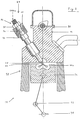
- FIG. 2 shows the common rail injection system 8 according to the invention Fig. 1 along the section axis II-II.
- the injector 24 is over the fastener 40 and the attachment 42 fixed in the rail 12 and in the Injector opening 28 of the cylinder head housing 14 inserted.
- the one in 3 only schematically indicated internal combustion engine 10 with a Engine housing 92 is only partially shown as a reciprocating piston engine formed in the piston 94, the combustion chamber 32 incorporated is.
- the injection nozzle 30 of the injector 24 projects into this combustion chamber 32 in.
- the piston 94 is via a crank mechanism 96 connected to a crankshaft 98, which is only hinted at is.
- FIG. 3 is the injection system 8 from FIG. 1 along the section III-III shown.
- the dashed circular lines 100 and the arrows 102 indicate the power transmission from the camshaft 90 via the spur gear 88 to the drive shaft 78 of the high pressure pump 16.
- Right angled to the drive shaft 78 is the plunger cylinder enclosed by the rail 12 46 arranged and with the supply line 58a for the inflow of the pressure medium Mistake.
- the internal combustion engine 10 is with its motor housing 92, piston 94, crank gear 96 and crankshaft 98 also only hinted at here.
- the injection system 8 it is advantageous for the functioning of the injection system 8 necessary that the rotational movement of the drive shaft 78 and that of the Camshaft 90 of the internal combustion engine 10 is operated in angular synchronism become.
- the drive shaft 78 is then preferably driven, for example, via the spur gear 88, in a known manner from the camshaft 90, as indicated in FIGS. 1 and 3. Due to the rotational movement of the drive shaft 78, mediated by the Eccentric 84, the plungers 54 perform stroke movements.
- the compression stroke of the plunger 54 closes the inlet valve 60 and the outlet valve 64 opens under pressure control and gives the passage 62 free.
- the pressure medium can thus through the passage 62 from the Delivery chamber 56 into the ring channel 50 and further into the channel 20a of the rail 12 stream. From there it flows further into the pressure space 20 of the rail 12 and through the inlet openings 38 into the interior of the injectors 24.
- the indicated injection process 104 becomes an electrical signal triggered and the print medium at high speed and high Pressure finely distributed into the combustion chamber 32.
- a is used instead of the rail 12 Housing cover 106 close to the side wall 68a of the Housing elements 68 arranged and that over the columns 72 between the used plunger cylinders 46 and the housing element 68 open Housing element 68 closed in this way.
- the Housing cover 106 analogous to the rail 12 receiving openings 44 for the Receiving the plunger cylinder 46 and have a channel 20a.
- the housing cover 106 which have a Press fit plunger 46 used so that everyone Delivery chamber 56 through the passage 62 and the through the annular groove Plunger cylinder 46 shaped ring channel 50 with the channel 20a of the Housing cover 106 is connected. That containing the plunger cylinders 46 Component, which in FIG.
- the housing cover 106 to which the Rail 12 is integrally formed on the dashed line 48.
- the rail 12 in a different way, e.g. about a high pressure hose with the channel 20a of the housing cover 106 would be connected.
- the housing element 68 itself can also have receiving openings 44 for the accommodation of the plunger cylinders 46 and a channel 20a may be provided, such that the plunger cylinders 46 directly into the housing element 68 a press fit can be used. They are here too Plunger cylinder 46 configured so that the delivery chamber 56 over the Passage 62 and the ring channel 50 is connected to the channel 20a.
- rail 12 only has openings 22 for receiving the Injectors 24 but not the receiving openings 44 for the plunger cylinders 46 on.
- the pressure chamber 20 of the rail 12 can then either over High pressure hoses with the channel 20a of the housing element 68 be connected or in that the rail 12 directly to the Housing element 68 is integrally formed.
- the housing element 68 Integrated part of the cylinder head housing 14 and thus the Motor housing 92.
- Other embodiments in which other parts of the pump housing 66 is an integral part of the motor housing 92 preferably the cylinder head housing 14 of the internal combustion engine 10 are, but are also conceivable.
- the rail 12 on the one hand the cylinder head housing 14 and on the other hand to the housing cover 106 or the housing element 68 can be integrally formed so that these elements over the rail 12 in the engine housing 92 or the cylinder head housing 14 to get integrated.
- Housing cover 106 or side plate 80 can also be in the engine housing 92 or the cylinder head housing 14 may be integrated or combinations of these parts.
Abstract
Description
Die Erfindung betrifft ein Common-Rail Einspritzsystem für Verbrennungsmotoren.The invention relates to a common rail injection system for internal combustion engines.
Common-Rail Einspritzsysteme werden bei Verbrennungsmotoren engesetzt, bei denen zur Optimierung der Verbrennungsleistung das Verbrennungsmedium in den Verbrennungskammern der einzelnen Zylinder fein zerstäubt vorliegen soll. Dazu wird das Verbrennungsmedium in einer Hochdruckpumpe verdichtet und über ein Rail auf die Injektoren der einzelnen Zylinder verteilt. Über ein elektrisches Signal wird schliesslich der Einspritzvorgang des Verbrennungsmediums in die Verbrennungskammer ausgelöst, wobei sich das unter hohem Druck stehende Verbrennungsmedium über die Einspritzdüsen der Injektoren mit hoher Geschwindigkeit fein in den Verbrennungskammern des Motors verteilt.Common rail injection systems are used in internal combustion engines, where the combustion medium is used to optimize the combustion performance in the combustion chambers of the individual cylinders should be atomized. For this, the combustion medium is in a High pressure pump compressed and on a rail on the injectors of the individual cylinder distributed. Finally, the electrical signal is transmitted Injection process of the combustion medium into the combustion chamber triggered, with the combustion medium under high pressure through the injectors of the injectors at high speed finely distributed in the combustion chambers of the engine.
Ein Einspritzsystem dieser Art ist beispielsweise im älteren CH-Patentgesuch Nr. 1997 1275/97 offenbart. Eine ein Pumpengehäuse aufweisende Hochdruckpumpe ist über einen Flansch an einem Motorengehäuse eines Verbrennungsmotors befestigt. Die Hochdruckpumpe arbeitet mit einem Plungerzylinder der zusammen mit einem Plungerkolben einen Förderraum begrenzt. Der Förderraum ist mit einer Leitung für den Zufluss des Druckmediums verbunden, der durch ein druckgesteuertes Einlassventil reguliert wird und der Plungerzylinder weist eine Durchlassöffnung für das Ausströmen des Druckmediums, das ebenfalls durch ein druckgesteuertes Ventil reguliert wird, auf. Der Plungerzylinder ist von einem Druckkörper umfasst, dessen Strömungskanäle die Durchlassöffnung des Plungerzylinders nach aussen verbinden. Über einen Hochdruckschlauch zwischen Druckkörper und Common-Rail oder dadurch, dass das Common-Rail direkt an den Druckkörper angeformt ist, werden die Strömungskanäle des Druckkörpers mit dem Druckraum des Rails verbunden. Die Verbindung zwischen den einzelnen Injektoren und dem Rail wird durch Hochdruckschläuche gewährleistet, die über entsprechende Anschlussstücke an den Injektoren bzw. dem Rail befestigt sind. Durch ihr separates Pumpengehäuse und durch die verschiedenen Verbindungsstücke und Anschlüsse weist diese Konstruktion viele verschiedene, z.T. recht kostspielige Teile auf, die in aufwendiger Montage zusammengesetzt werden müssen.An injection system of this type is, for example, in the older CH patent application No. 1997 1275/97. A pump housing High pressure pump is a flange on a motor housing Internal combustion engine attached. The high pressure pump works with one Plunger cylinder which, together with a plunger, creates a delivery chamber limited. The delivery chamber is with a line for the inflow of the pressure medium connected, which is regulated by a pressure-controlled inlet valve and the plunger cylinder has a passage for the outflow of the pressure medium, which is also controlled by a pressure-controlled valve is regulated on. The plunger cylinder is surrounded by a pressure body, whose flow channels follow the passage opening of the plunger cylinder connect outside. Via a high pressure hose between the pressure body and common rail or in that the common rail directly to the Pressure body is molded, the flow channels of the pressure body connected to the pressure chamber of the rail. The connection between the individual injectors and the rail is through high pressure hoses ensures that via appropriate connectors on the injectors or the rail are attached. With its separate pump housing and due to the various connectors and connections this shows Construction many different, partly quite expensive parts that are in complex assembly must be assembled.
JP-A-09 060562 offenbart einen Verbrennungsmotor mit Direkteinspritzung, bei dem eine Hochdruckbrennstoffpumpe mit dem Zylinderkopf verbunden ist. Der Zylinderkopf weist in seinem Innern einen Kanal auf, durch den der Brennstoff von der Hochdruckbrennstoffpumpe weggefördert wird. Das auf die Einspritzventile aufgesetzte Common-Rail ist mit dem Zylinderkopf verbunden und weist in seinem Innern einen Durchlass zum Verteilen des Brennstoffs an die Einspritzventile auf.JP-A-09 060562 discloses an internal combustion engine with direct injection, where a high pressure fuel pump with the cylinder head connected is. The cylinder head has a channel inside through which the fuel is pumped away from the high pressure fuel pump becomes. The common rail placed on the injection valves is included connected to the cylinder head and has a passage in its interior to distribute the fuel to the injectors.
Bei der aus der US-Patentschrift Nr. 5,603,303 bekannten Konstruktion, wird aus einem Plungerzylinder und einer Kolbenführung ein Pumpengehäuse für eine Hochdruckpumpe gebildet. Dieses aus Plungerzylinder und Kolbenführung bestehende Pumpengehäuse durchgreift in einer passenden Öffnung ein Motorengehäuse in der Art, dass ein Teil des Pumpengehäuses aus dem Motorengehäuse herausragt und mittels Bolzen direkt an diesem befestigt ist. Auch diese Konstruktion ist im Aufbau und in der Montage aufwendig.In the construction known from US Pat. No. 5,603,303, a pump housing is created from a plunger cylinder and a piston guide formed for a high pressure pump. This from plunger cylinder and Existing pump housing engages in a suitable piston guide Opening a motor housing in the way that part of the pump housing protrudes from the motor housing and directly on this by means of bolts is attached. This construction is also in construction and assembly complex.
Die vorliegende Erfindung hat sich die Aufgabe gestellt, ein Common-Rail Einspritzsystem zur Verfügung zu stellen, das einen verbesserten und vor allem einfacheren Aufbau aufweist.The present invention has set itself the task of a common rail To provide an improved injection system and before has a simpler structure.
Diese Aufgabe wird gelöst durch ein Common-Rail Einspritzsystem mit den Merkmalen gemäss Anspruch 1.This problem is solved by a common rail injection system with the Features according to claim 1.
Das Einspritzsystem besitzt ein mit einer Hochdruckpumpe verbundenes langgestrecktes Rail, das entlang seiner Längsachse einen Druckraum aufweist. Den Druckraum durchstossend sind Öffnungen für die direkte Aufnahme von Injektoren vorgesehen. Der Vorteil einer solchen Konstruktion liegt darin, dass die Injektoren direkt in das Rail eingesetzt werden können, was die Montage sehr vereinfacht. Eine weitere Vereinfachung bringt das Einsetzen eines Plungerzylinders in eine dafür vorgesehene Aufnahmeöffnung des Rails. Wird der Plungerzylinder über eine Presspassung in der Aufnahmeöffnung des Rails fixiert, so wirkt sich dies in gleicher Art und Weise aus wie die Umfassung durch einen Druckkörper, die im älteren CH-Patentgesuch Nr. 1997 1275/97 beschrieben ist. Wie dort ausgeführt, können durch die Umfassung der Plungerzylinder durch einen Druckkörper verschiedene Vorteile wie z.B. die Belastung der Hochdruckpumpe mit höheren Drücken erzielt werden.The injection system is connected to a high pressure pump elongated rail, which has a pressure chamber along its longitudinal axis. Openings for direct reception penetrate the pressure chamber provided by injectors. The advantage of such a construction is that the injectors can be inserted directly into the rail, which makes assembly very easy. This brings a further simplification Insert a plunger cylinder in a designated opening of the rail. If the plunger cylinder has a press fit in the Fixing opening of the rail fixed, this affects in the same way and Way out as the encirclement by a pressure body, which in the older CH patent application No. 1997 1275/97. As stated there can by surrounding the plunger cylinder by a pressure body various advantages such as the load on the high pressure pump higher pressures can be achieved.
In einer bevorzugten Ausführungsform weisen die eingesetzten Injektoren in dem Bereich, der nach dem Einsetzen auf Höhe des Druckraumes des Rails liegt, Einlassöffnungen auf, durch die das Druckmedium in die Injektoren strömen und von dort in die Verbrennungskammern verspritzt werden kann. Der Vorteil liegt darin, dass das Druckmedium aus der Druckkammer des Rails direkt in die Injektoren einströmen kann. Die Montage wird dadurch sehr vereinfacht und durch den Wegfall der Verbindungsteile können Materialkosten eingespart werden.In a preferred embodiment, the injectors used have in the area that after insertion at the pressure chamber of the Rails lies on inlet openings through which the pressure medium enters the injectors flow and are sprayed from there into the combustion chambers can. The advantage is that the pressure medium from the pressure chamber of the rail can flow directly into the injectors. The assembly will thereby very simplified and by eliminating the connecting parts material costs can be saved.
Eine besonders einfache Ausführungsform ist in Anspruch 3 beschrieben. Die Öffnungen für die Injektoren im Rail sind mit ihren Öffnungsachsen parallel zueinander ausgerichtet und liegen vorzugsweise in einer Ebene. Dadurch wird das Einbringen der Öffnungen für die Injektoren sowohl im Rail als auch im Zylinderkopfgehäuse und das Einsetzen der Injektoren in die Öffnungen vereinfacht. Dies ist speziell für die Serienproduktion in der Industrie von grosser Bedeutung.A particularly simple embodiment is described in claim 3. The openings for the injectors in the rail are with their opening axes aligned parallel to each other and are preferably in one plane. This will make the openings for the injectors both in the Rail as well as in the cylinder head housing and inserting the injectors in the openings simplified. This is especially for series production in the Industry of great importance.
Die parallele Achsenführung der Aufnahmeöffnung für den Plungerzylinder und der Öffnungen für die Injektoren vereinfacht wiederum das Einbringen der Öffnungen und die Montage des gesamten Systems. Ausserdem ermöglicht dies eine geradlinige Ausbildung des Rails.The parallel axis guidance of the receiving opening for the plunger cylinder and the openings for the injectors in turn simplify insertion of the openings and assembly of the entire system. Also made possible this is a straightforward design of the rail.
Weiter vereinfacht werden kann das Einspritzsystem, wenn das Rail einen Teil des Pumpengehäuses bildet, insbesondere wenn es einstückig an das Pumpengehäuse bzw. den Gehäusedeckel angeformt ist.The injection system can be further simplified if the rail connects one Forms part of the pump housing, especially if it integrally with the Pump housing or the housing cover is molded.
Neben einer sehr einfachen Montage und einem einfachen Aufbau kann durch die Integration des Pumpengehäuses der Hochdruckpumpe in ein Motorengehäuse, vorzugsweise in ein Zylinderkopfgehäuse eines Verbrennungsmotors, eine Gewichtsersparnis erzielt werden.In addition to a very simple assembly and a simple structure by integrating the pump housing of the high pressure pump into one Engine housing, preferably in a cylinder head housing of an internal combustion engine, a weight saving can be achieved.
Eine weitere Vereinfachung des Einspritzsystems und damit auch seiner Montage kann durch bevorzugte Ausführungsformen, wie sie in den weiteren abhängigen Ansprüchen definiert sind, erreicht werden.A further simplification of the injection system and thus also its Assembly can be carried out by preferred embodiments, as described in the further dependent claims are defined.
Das erfindungsgemässe Common-Rail Einspritzsystem wird nun anhand eines Ausführungsbeispieles, das mehrere der verschiedenen Vereinfachungsmöglichkeiten kombiniert, näher beschrieben. Es zeigen rein schematisch:
- Fig. 1
- im Längsschnitt einen Teil eines erfindungsgemässen Common-Rail Einspritzsystems;
- Fig. 2
- in einem Schnitt entlang der Linie II-II der Fig. 1, das dort gezeigte Einspritzsystem; und
- Fig. 3
- in einem Schnitt entlang der Linie III-III der Fig. 1, das dort gezeigte Einspritzsystem mit einem teilweise geschnitten dargestellten Verbrennungsmotor.
- Fig. 1
- in longitudinal section a part of a common rail injection system according to the invention;
- Fig. 2
- in a section along the line II-II of Figure 1, the injection system shown there. and
- Fig. 3
- in a section along the line III-III of Fig. 1, the injection system shown there with a partially cut internal combustion engine.
Der in Fig. 1 dargestellte Teil des erfindungsgemässen Common-Rail Einspritzsystems
8 eines auch in Fig. 2 und 3 andeutungsweise dargestellten
Verbrennungsmotors 10 zeigt ein langgestrecktes, geradliniges Rail 12, das
parallel zu einem zum Verbrennungsmotor 10 gehörenden Zylinderkopfgehäuse
14 angeordnet ist, und eine Hochdruckpumpe 16 deren
Antrieb in bekannter, später noch genauer beschriebener Weise vom
Verbrennungsmotor 10 aus erfolgt.The part of the common rail injection system according to the invention shown in FIG. 1
8 one also indicated in FIGS. 2 and 3
Das Rail weist entlang seiner Längsachse 18 einen Druckraum 20 und
senkrecht dazu, das Rail 12 im Bereich des Druckraumes 20 durchstossend,
Öffnungen 22 für die Aufnahme von Injektoren 24 auf. Die
Öffnungen 22 sind mit ihren Öffnungsachsen 26 parallel zueinander
angeordnet und liegen in einer Ebene. In ihrer Verlängerung bilden die
Öffnungsachsen 26 auch die Achsen von Injektorenöffnungen 28 des
Zylinderkopfgehäuses 14. Somit liegen schliesslich auch die Injektoren 24,
wenn sie durch die Öffnungen 22 des Rails 12 hindurch in die Injektorenöffnungen
28 des Zylinderkopfgehäuses 14 eingesetzt werden mit
ihren Injektorenachsen 26a parallel zueinander und in einer Ebene.The rail has a pressure chamber 20 and along its
Wie in Fig. 1 und 2 dargestellt, weisen die Injektoren 24, die im wesentlichen
rotationssymmetrisch ausgebildet sind, an einem Ende Einpritzdüsen
30 auf. Die Injektoren 24 sind so ausgeformt, dass die Einpritzdüsen 30
nach der Montage in eine in Fig. 2 dargestellte Verbrennungskammer 32
des Verbrennungsmotors 10 hineinragen. Ein der Einspritzdüse 30
gegenüberliegender Injektorenkopf 34 ragt über das Rail 12 hinaus. Wie
Fig.1 zeigt, weisen die Injektoren 24 in dem Abschnitt, der nach dem
Einsetzen der Injektoren 24 in der Höhe des Druckraumes 20 des Rails 12
liegt, eine Umfangsnut 36 auf, durch die gewährleistet wird, dass die
Injektoren 24 vom im Druckraum 20 befindlichen Druckmedium umströmt
werden können. In diesem Abschnitt der Injektoren 24 befinden sich auch
Einlassöffnungen 38, durch die das Druckmedium in die Injektoren 24
einströmen kann. Mit Hilfe eines Befestigungselementes 40, beispielsweise
einer Schraubverbindung, im Bereich des über das Rail 12 hinausragenden
Injektorkopfes 34 und eines Anlagers 42 auf der gegenüberliegenden
Aussenwand des Rails 12 werden die Injektoren 24 im Rail 12 fixiert.As shown in FIGS. 1 and 2, the
Auf der Seite der Hochdruckpumpe 16 weist das Rail 12 zwei Aufnahmeöffnungen
44 für die Aufnahme von Plungerzylindern 46 und einen
Kanal 20a auf. Der Kanal 20a geht bei der gestrichelten Linie 48 in den
Druckraum 20 des Rails 12 über und verbindet die Aufnahmeöffnungen 44
mit dem Druckraum 20 des Rails 12. Damit das Druckmedium die eingesetzten
Plungerzylinder 46 umströmen kann, sind in Höhe des Kanals
20a umfangsseitig Ringnuten in die Plungerzylinder 46 eingelassen, die bei
eingesetzten Plungerzylindern 46 einen Ringkanal 50 (gestrichelt angedeutet)
um die Plungerzylinder 46 bilden. Die Plungerzylinder 46 sind über
eine Presspassung im Rail 12 fixiert, was die gleiche Wirkung wie das
Umfassen der Plungerzylinder mit einem Druckkörper hat, wie dies im älteren
CH-Patentgesuch Nr. 1997 1275/97 beschrieben ist.On the side of the
Die ins Rail 12 eingebrachten Aufnahmeöffnungen 44 für die Plungerzylinder
46 weisen parallel zueinander liegende Achsen 52 auf, die in einer
Ebene mit und parallel zu den Öffnungsachsen 26 der Öffnungen 22 im
Rail 12 bzw. den Injektorenachsen 26a der Injektoren 24 angeordnet sind.
Dies führt dazu, dass auch die Plungerzylinder 46 nach ihrem Einsetzen in
die Aufnahmeöffnungen 44 mit ihren Plungerachsen 52a parallel und in
einer Ebene zu den Öffnungsachsen 26 bzw. den Injektorenachsen 26a liegen.The receiving openings 44 made in the
Jeder Plungerzylinder 46 begrenzt zusammen mit einem Plungerkolben 54
einen Förderraum 56. Dieser Förderraum 56 ist über einen in den Plungerzylinder
46 eingelassenen Zuflusskanal 58 und eine Zuleitung 58a mit
einem nicht dargestellten Reservoir für das Druckmedium verbunden. Der
Zufluss des Druckmediums wird durch ein druckgesteuertes Einlassventil
60 reguliert. Über einen Durchlass 62, der in den Plungerzylinder 46 eingearbeitet
ist, und den Förderraum 56 mit dem Ringkanal 50 verbindet,
kann das Druckmedium, reguliert durch ein ebenfalls druckgesteuertes
Auslassventil 64, wieder aus dem Förderraum 56 ausströmen.Each
Die Hochdruckpumpe 16 weist ein Pumpengehäuse 66 auf, zu dem unter
anderem ein Gehäuseelement 68 mit einer Seitenwand 68a gehört, in der
Gehäuseöffnungen 70 ausgenommen sind. Die Plungerzylinder 46 ragen
nun mit der Seite, in der die Plungerkolben 54 in den Plungerzylindern 46
geführt sind, in diese Gehäuseöffnungen 70 der Seitenwand 68a des Gehäuseelements
68 hinein. Dabei sind die Gehäuseöffnungen 70 so
ausgestaltet, dass zwischen den eingesetzten Plungerzylindern 46 und dem
Gehäuseelement 68 ein kleiner Spalt 72 bleibt, so dass die Plungerzylinder
46 mit etwas Spiel in das Gehäuseelement 68 eingesetzt werden können.
Über die Spalten 72 ist das Gehäuseelement 68 über die Seitenwand 68a
gegen aussen offen. Durch das Rail 12, das auf der Seitenwand 68a des
Gehäuseelements 68 enganschliessend angeordnet ist, wird das Gehäuseelement
68 wie durch einen Deckel verschlossen.The
In einer senkrecht zu dieser Seitenwand 68a liegenden Wand 74 des
Gehäuseelementes 68 ist auf der Innenseite eine als Lager ausgeformten
Aussparung 76 eingearbeitet, in der die Antriebswelle 78 mit ihrem der
Kraftübertragung gegenüberliegenden Endbereich 78a gelagert ist. Auf der
anderen Seite geht die Wand 74 bei der gestrichelten Trennlinie 74a in das
einstückig angeformte Zylinderkopfgehäuse 14 über. Gegenüber der Wand
74 des Gehäuseelementes 68 verschliesst eine Seitenplatte 80, die
ebenfalls zum Pumpengehäuse 66 gehört, eine weiter Öffnung des Gehäuseelements
68. In einer Lageröffnung 82 dieser Seitenplatte 80 ist die
Antriebswelle 78 auf ihrer der Kraftübertragung zugewandten Seite
gelagert. Bei Reparaturen ist über diese Seitenplatte 80 auch der Zugang in
das Innere des Pumpengehäuses 66 ermöglicht.In a wall 74 of the wall lying perpendicular to this
Die Plungerzylinder 46 mit den Plungerkolben 54 und die Antriebswelle 78
der Hochdruckpumpe 16 sind rechtwinklig zueinander angeordnet. Für die
Hubbewegung der - mittels Druckfedern 83 in Richtung gegen die
Antriebswelle 78 gedrängten - Plungerkolben 54 in den Plungerzylindern 46
der Hochdruckpumpe 16 sind auf der Antriebswelle 78 der Hochdruckpumpe
16 Exzenter 84 angebracht. Zwischen den Exzentern 84 und
den Plungerkolben 54 sind in bekannter Art und Weise Abwälzringe 86
angebracht, die sich frei auf den Exzentern 84 drehen können. Für den
Antrieb der Hochdruckpumpe 16 ist in der hier gezeigten Ausführungsform
die Antriebswelle 78 über ein in Fig. 1 und Fig. 3 angedeutetes Stirnradgetriebe
88 mit einer ebenfalls nur andeutungsweise dargestellten Nockenwelle
90 des Verbrennungsmotors 10 gekoppelt.The
Fig. 2 zeigt das erfindungsgemässe Common-Rail Einspritzsystem 8 aus
Fig. 1 entlang der Schnittachse II-II. Der Injektor 24 ist über das Befestigungselement
40 und das Anlager 42 im Rail 12 fixiert und in die
Injektorenöffnung 28 des Zylinderkopfgehäuses 14 eingesetzt. Der auch in
den Fig. 3 nur schematisch angedeutete Verbrennungsmotor 10 mit einem
nur teilweise dargestellten Motorengehäuse 92 ist als Hubkolbenmotor
ausgebildet, in dessen Kolben 94 die Verbrennungskammer 32 eingearbeitet
ist. Die Einspritzdüse 30 des Injektors 24 ragt in diese Verbrennungskammer
32 hinein. Der Kolben 94 ist über ein Kurbelgetriebe 96
mit einer Kurbelwelle 98 verbunden, was nur andeutungsweise dargestellt
ist.2 shows the common rail injection system 8 according to the invention
Fig. 1 along the section axis II-II. The
In Fig. 3 ist das Einspritzsystem 8 aus Fig. 1 entlang dem Schnitt III-III
dargestellt. Die gestrichelt gezeichneten Kreislinien 100 und die Pfeile 102
deuten die Kraftübertragung von der Nockenwelle 90 über das Stirnradgetriebe
88 an die Antriebswelle 78 der Hochdruckpumpe 16 an. Rechtwinkelig
zur Antriebswelle 78 ist der vom Rail 12 umfasste Plungerzylinder
46 angeordnet und mit der Zuleitung 58a für den Zufluss des Druckmediums
versehen. Der Verbrennungsmotor 10 ist mit seinem Motorengehäuse
92, Kolben 94, Kurbelgetriebe 96 und der Kurbelwelle 98 auch
hier nur angedeutet.3 is the injection system 8 from FIG. 1 along the section III-III
shown. The dashed
Für die Funktionsweise des Einspritzsystems 8 ist es vorteilhaft aber nicht
notwendig, dass die Drehbewegung der Antriebswelle 78 und die der
Nockenwelle 90 des Verbrennungsmotors 10 winkelsynchron betrieben
werden. Vorzugsweise erfolgt dann der Antrieb der Antriebswelle 78,
beispielsweise über das Stirnradgetriebe 88, in bekannter Art und Weise
von der Nockenwelle 90 aus, wie dies in den Fig. 1 und 3 angedeutet ist.
Aufgrund der Drehbewegung der Antriebswelle 78, vermittelt durch die
Exzenter 84, führen die Plungerkolben 54 Hubbewegungen aus. Bei einem
Saughub des Plungerkolbens 54 öffnet sich druckgesteuert das Einlassventil
60 und das Druckmedium strömt aus dem Reservoir über die
Zuleitung 58a und den Zuflusskanal 58 in den Förderraum 56. Bei einem
Kompressionshub des Plungerkolbens 54 schliesst sich das Einlassventil 60
und das Auslassventil 64 öffnet druckgesteuert und gibt den Durchlass 62
frei. Das Druckmedium kann so über den Durchlass 62 aus dem
Förderraum 56 in den Ringkanal 50 und weiter in den Kanal 20a des Rails
12 strömen. Von dort aus strömt es weiter in den Druckraum 20 des Rails
12 und durch die Einlassöffnungen 38 in das Innere der Injektoren 24. Über
ein elektrisches Signal wird der angedeutete Einspritzvorgang 104
ausgelöst und das Druckmedium mit hoher Geschwindigkeit und hohem
Druck fein in die Verbrennungskammer 32 hinein verteilt.However, it is advantageous for the functioning of the injection system 8
necessary that the rotational movement of the
Andere Antriebsmöglichkeiten als die oben beschriebene von der
Nockenwelle 90 über ein Stirnradgetriebe 88 an die Antriebswelle 78 sind
natürlich ebenso möglich. So ist statt eines Stirnradgetriebes 88 z.B. auch
die Kraftübertragung mittels eines Riementriebes denkbar, oder ein Antrieb
statt von der Nockenwelle 90 direkt von der Kurbelwelle 98 aus.Different drive options than the one described above by the
In einer unterschiedlichen Ausführungsform wird an Stelle des Rails 12 ein
Gehäusedeckel 106 enganschliessend an die Seitenwand 68a des
Gehäuseelments 68 angeordnet und das über die Spalten 72 zwischen den
eingesetzten Plungerzylindern 46 und dem Gehäuseelment 68 offene
Gehäuseelement 68 auf diese Weise verschlossen. Dazu muss der
Gehäusedeckel 106 analog zum Rail 12 Aufnahmeöffnungen 44 für die
Aufnahme der Plungerzylinder 46 und einen Kanal 20a aufweisen. Wie in
das Rail 12 sind auch in den Gehäusedeckel 106, die über eine
Presspassung eingesetzten Plungerzylinder 46 so ausgestaltet, dass jeder
Förderraum 56 über den Durchlass 62 und den durch die Ringnut am
Plungerzylinder 46 geformten Ringkanal 50 mit dem Kanal 20a des
Gehäusedeckels 106 verbunden ist. Das die Plungerzylinder 46 enthaltende
Bauteil, das in Fig. 1 enganschliessend an das Gehäuseelement 68
angeordnet ist, kann also auch der Gehäusedeckel 106 sein, an den das
Rail 12 bei der gestrichelten Linie 48 einstückig angeformt ist. Genauso
wäre aber auch denkbar, dass das Rail 12 auf eine andere Weise, z.B. über
einen Hochdruckschlauch, mit dem Kanal 20a des Gehäusedeckels 106
verbunden wäre.In a different embodiment, a is used instead of the
Auch das Gehäuseelement 68 selbst kann mit Aufnahmeöffnungen 44 für
die Aufnahme der Plungerzylinder 46 und einem Kanal 20a versehen sein,
derart dass die Plungerzylinder 46 direkt in das Gehäuseelement 68 mit
einer Presspassung eingesetzt werden können. Auch hier sind die
Plungerzylinder 46 so ausgestaltet, dass der Förderraum 56 über den
Durchlass 62 und den Ringkanal 50 mit dem Kanal 20a verbunden ist. Das
Rail 12 weist in diesem Fall nur die Öffnungen 22 für die Aufnahme der
Injektoren 24 nicht aber die Aufnahmeöffnungen 44 für die Plungerzylinder
46 auf. Der Druckraum 20 des Rails 12 kann dann entweder über
Hochdruckschläuche mit dem Kanal 20a des Gehäuseelements 68
verbunden sein oder dadurch, dass das Rail 12 direkt an das
Gehäuseelement 68 angeformt ist.The
In der in Fig. 1 dargestellten Ausführungsform ist das Gehäuseelement 68
integrierter Bestandteil des Zylinderkopfgehäuses 14 und damit des
Motorengehäuses 92. Andere Ausführungsformen, bei denen andere Teile
des Pumpengehäuses 66 integrierter Bestandteil des Motorengehäuses 92
vorzugsweise des Zylinderkopfgehäuses 14 des Verbrennungsmotors 10
sind, sind aber ebenso denkbar. Dabei kann z.B. das Rail 12 einerseits an
das Zylinderkopfgehäuse 14 und andererseits an den Gehäusedeckel 106
oder das Gehäuseelement 68 angeformt sein, so dass diese Elemente über
das Rail 12 in das Motoerengehäuse 92 bzw. deas Zylinderkopfgehäuse 14
integriert werden. Auch Gehäusedeckel 106 oder Seitenplatte 80 können in
das Motorengehäuse 92 oder das Zylinderkopfgehäuse 14 integriert sein
oder Kombintionen dieser Teile.In the embodiment shown in FIG. 1, the
Um ein Umströmen der Injektoren 24 und der Plungerzylinder 46 durch das
Druckmedium zu gewährleisten, können auch andere Möglichkeiten als die
Umfangsnuten 36 an den Injektoren 24 und die den Ringkanal 50
mitformenden umfangseitigen Ringnuten an den Plungerzylindern 46
vorgesehen werden. Denkbar wären z.B. ringförmige Nuten an der
Innenseite der Öffnungen 26 für die Injektoren 24 bzw. in den
Aufnahmeöffnungen 44 für die Plungerzylinder 46. Auch wäre es
vorstellbar, dass die Injektoren 24 statt über ein Befestigungselement 40
und ein Anlager 42 auf eine andere Art und Weise mit dem Rail 12
verbunden werden, beispielsweise durch eine Schrumpfpassung. Ebenso
können auch die Plungerzylinder 46 auf eine andere Weise als über eine
Presspassung in den Aufnahmeöffnungen 44 fixiert sein. Für die
Funktionsweise ist es auch prinzipiell nicht von entscheidender Bedeutung
ob der Plungerzylinder 46 aus dem den Plungerzylinder 46 aufnehmenden
Bauteil hinausragt, eben mit diesem abschliesst oder von ihm überdeckend
eingefasst wird. Dies gilt ebenso für die Injektoren 24 im Rail 12. Auch die
Ausrichtung der Achsen 52 der Aufnahmeöffnungen 44 für die
Plungerzylinder 46 und der Öffnungsachsen 26 der Öffnungen 22 für die
Injektoren 24 müssen nicht zwingend parallel und in einer Ebene
angeordnet sein. Auch andere Ausrichtungen sind vorstellbar.To flow around the
Claims (9)
Applications Claiming Priority (3)
| Application Number | Priority Date | Filing Date | Title |
|---|---|---|---|
| CH255797 | 1997-11-05 | ||
| CH2557/97 | 1997-11-05 | ||
| CH255797 | 1997-11-05 |
Publications (2)
| Publication Number | Publication Date |
|---|---|
| EP0915252A2 true EP0915252A2 (en) | 1999-05-12 |
| EP0915252A3 EP0915252A3 (en) | 2000-03-15 |
Family
ID=4236484
Family Applications (1)
| Application Number | Title | Priority Date | Filing Date |
|---|---|---|---|
| EP98117887A Withdrawn EP0915252A3 (en) | 1997-11-05 | 1998-09-21 | Common rail fuel injection system |
Country Status (3)
| Country | Link |
|---|---|
| EP (1) | EP0915252A3 (en) |
| JP (1) | JPH11200986A (en) |
| CA (1) | CA2251148A1 (en) |
Cited By (11)
| Publication number | Priority date | Publication date | Assignee | Title |
|---|---|---|---|---|
| EP0990792A2 (en) * | 1998-09-30 | 2000-04-05 | SIG Schweizerische Industrie-Gesellschaft | Common-Rail fuel injection system |
| WO2001023749A1 (en) * | 1999-09-29 | 2001-04-05 | Robert Bosch Gmbh | High pressure fuel accumulator |
| EP1101931A2 (en) | 1999-11-19 | 2001-05-23 | CRT Common Rail Technologies AG | High pressure common rail injection system |
| WO2004079182A1 (en) * | 2003-03-04 | 2004-09-16 | Siemens Aktiengesellschaft | High pressure fuel accumulator |
| EP1298316A3 (en) * | 2001-09-26 | 2005-02-02 | DEUTZ Aktiengesellschaft | Fuel injection system |
| EP2088310A1 (en) * | 2008-02-08 | 2009-08-12 | DEUTZ Aktiengesellschaft | Internal combustion engine with a Common Rail injection system |
| WO2011088958A1 (en) * | 2010-01-22 | 2011-07-28 | Robert Bosch Gmbh | High-pressure pump |
| DE102010051883A1 (en) * | 2010-11-22 | 2012-05-24 | Benteler Automobiltechnik Gmbh | Fuel distributor for supplying fuel to injection valves of combustion engine, has sleeve fitted in pipe in fluid-tight manner and provided with passage for feedthrough of fastening element, where recess is formed transverse to passage |
| DE102015205170A1 (en) | 2015-03-23 | 2016-09-29 | Bayerische Motoren Werke Aktiengesellschaft | Fuel injector |
| DE102015205169A1 (en) | 2015-03-23 | 2016-09-29 | Bayerische Motoren Werke Aktiengesellschaft | Fuel injector |
| DE102015209646A1 (en) | 2015-05-27 | 2016-12-01 | Bayerische Motoren Werke Aktiengesellschaft | Fuel injector |
Families Citing this family (5)
| Publication number | Priority date | Publication date | Assignee | Title |
|---|---|---|---|---|
| US9200563B2 (en) | 2013-03-12 | 2015-12-01 | Pratt & Whitney Canada Corp. | Internal combustion engine with common rail pilot and main injection |
| US9896998B2 (en) | 2015-02-20 | 2018-02-20 | Pratt & Whitney Canada Corp. | Compound engine assembly with modulated flow |
| US9932892B2 (en) | 2015-02-20 | 2018-04-03 | Pratt & Whitney Canada Corp. | Compound engine assembly with coaxial compressor and offset turbine section |
| US9797297B2 (en) | 2015-02-20 | 2017-10-24 | Pratt & Whitney Canada Corp. | Compound engine assembly with common inlet |
| US9879591B2 (en) | 2015-02-20 | 2018-01-30 | Pratt & Whitney Canada Corp. | Engine intake assembly with selector valve |
Citations (3)
| Publication number | Priority date | Publication date | Assignee | Title |
|---|---|---|---|---|
| CH127597A (en) | 1927-05-25 | 1928-09-01 | Sulzer Ag | Standing piston machine, in particular internal combustion engine. |
| US5603303A (en) | 1994-04-28 | 1997-02-18 | Nippondenso Co., Ltd. | High pressure fuel supply pump |
| JPH0960562A (en) | 1995-08-24 | 1997-03-04 | Nissan Motor Co Ltd | Direct injection-type internal combustion engine |
Family Cites Families (4)
| Publication number | Priority date | Publication date | Assignee | Title |
|---|---|---|---|---|
| FR2701295B1 (en) * | 1993-02-05 | 1995-04-28 | Sindra Sa | Fuel injection rail and one of its manufacturing processes. |
| US5538403A (en) * | 1994-05-06 | 1996-07-23 | Cummins Engine Company, Inc. | High pressure pump for fuel injection systems |
| JP2689226B2 (en) * | 1994-12-02 | 1997-12-10 | 株式会社ゼクセル | Fuel pump for high pressure fuel injector |
| JPH0988761A (en) * | 1995-09-26 | 1997-03-31 | Isuzu Motors Ltd | Fuel injection device of internal combustion engine |
-
1998
- 1998-09-21 EP EP98117887A patent/EP0915252A3/en not_active Withdrawn
- 1998-10-14 JP JP10291931A patent/JPH11200986A/en active Pending
- 1998-10-19 CA CA002251148A patent/CA2251148A1/en not_active Abandoned
Patent Citations (3)
| Publication number | Priority date | Publication date | Assignee | Title |
|---|---|---|---|---|
| CH127597A (en) | 1927-05-25 | 1928-09-01 | Sulzer Ag | Standing piston machine, in particular internal combustion engine. |
| US5603303A (en) | 1994-04-28 | 1997-02-18 | Nippondenso Co., Ltd. | High pressure fuel supply pump |
| JPH0960562A (en) | 1995-08-24 | 1997-03-04 | Nissan Motor Co Ltd | Direct injection-type internal combustion engine |
Cited By (17)
| Publication number | Priority date | Publication date | Assignee | Title |
|---|---|---|---|---|
| EP0990792A3 (en) * | 1998-09-30 | 2003-05-21 | CRT Common Rail Technologies AG | Common-Rail fuel injection system |
| EP0990792A2 (en) * | 1998-09-30 | 2000-04-05 | SIG Schweizerische Industrie-Gesellschaft | Common-Rail fuel injection system |
| WO2001023749A1 (en) * | 1999-09-29 | 2001-04-05 | Robert Bosch Gmbh | High pressure fuel accumulator |
| EP1101931A2 (en) | 1999-11-19 | 2001-05-23 | CRT Common Rail Technologies AG | High pressure common rail injection system |
| US6330876B1 (en) | 1999-11-19 | 2001-12-18 | Crt Common Rail Technologies Ag | High-pressure injection system with common rail |
| US6745753B2 (en) | 1999-11-19 | 2004-06-08 | Crt Common Rail Technologies Ag | High-pressure injection system |
| EP1298316A3 (en) * | 2001-09-26 | 2005-02-02 | DEUTZ Aktiengesellschaft | Fuel injection system |
| US7040289B2 (en) | 2003-03-04 | 2006-05-09 | Siemens Aktiengesellschaft | High pressure fuel accumulator |
| WO2004079182A1 (en) * | 2003-03-04 | 2004-09-16 | Siemens Aktiengesellschaft | High pressure fuel accumulator |
| US7182069B2 (en) | 2003-03-04 | 2007-02-27 | Siemens Aktiengesellschaft | High pressure fuel accumulator |
| EP2088310A1 (en) * | 2008-02-08 | 2009-08-12 | DEUTZ Aktiengesellschaft | Internal combustion engine with a Common Rail injection system |
| WO2011088958A1 (en) * | 2010-01-22 | 2011-07-28 | Robert Bosch Gmbh | High-pressure pump |
| DE102010051883A1 (en) * | 2010-11-22 | 2012-05-24 | Benteler Automobiltechnik Gmbh | Fuel distributor for supplying fuel to injection valves of combustion engine, has sleeve fitted in pipe in fluid-tight manner and provided with passage for feedthrough of fastening element, where recess is formed transverse to passage |
| DE102010051883B4 (en) * | 2010-11-22 | 2016-06-02 | Benteler Automobiltechnik Gmbh | Fuel distributor |
| DE102015205170A1 (en) | 2015-03-23 | 2016-09-29 | Bayerische Motoren Werke Aktiengesellschaft | Fuel injector |
| DE102015205169A1 (en) | 2015-03-23 | 2016-09-29 | Bayerische Motoren Werke Aktiengesellschaft | Fuel injector |
| DE102015209646A1 (en) | 2015-05-27 | 2016-12-01 | Bayerische Motoren Werke Aktiengesellschaft | Fuel injector |
Also Published As
| Publication number | Publication date |
|---|---|
| EP0915252A3 (en) | 2000-03-15 |
| JPH11200986A (en) | 1999-07-27 |
| CA2251148A1 (en) | 1999-05-05 |
Similar Documents
| Publication | Publication Date | Title |
|---|---|---|
| EP1931875B1 (en) | High pressure pump, in particular for a fuel injection device of an internal combustion engine | |
| EP0391366B1 (en) | Fuel injection apparatus | |
| EP0915252A2 (en) | Common rail fuel injection system | |
| DE3732259C2 (en) | Method and device for injecting fuel into an internal combustion engine | |
| EP1714030B1 (en) | High-pressure pump, particularly for a fuel injection device of a combustion engine | |
| DE4237469A1 (en) | Fuel injection device, in particular pump nozzle for internal combustion engines | |
| EP1561028B1 (en) | High-pressure fuel pump comprising a ball valve in the low-pressure inlet | |
| DE102018214212A1 (en) | High-pressure fuel pump | |
| WO2013092968A2 (en) | Pump, in particular a high pressure fuel pump for a fuel injection device | |
| WO2011131481A1 (en) | High-pressure pump | |
| DE3221405A1 (en) | FUEL INJECTION PUMP FOR INTERNAL COMBUSTION ENGINES | |
| DE10129449A1 (en) | High-pressure fuel pump for internal combustion engines with improved part-load behavior | |
| WO2004055368A1 (en) | High pressure pump for a fuel injection device for an internal combustion engine | |
| EP0990792A2 (en) | Common-Rail fuel injection system | |
| EP1361357A2 (en) | Fuel pump, in particular for an internal combustion engine with direct injection | |
| DE4437927A1 (en) | Injector with solenoid valve control for fuel injection into the combustion chamber of a diesel engine | |
| EP1537334B1 (en) | Pump, especially for a fuel injection device for an internal combustion engine | |
| EP0881380A1 (en) | High-pressure feed pump | |
| EP1211419A2 (en) | Device for pumping fluids, especially fuel | |
| DE102004019626B4 (en) | Fuel injection pump and rotary / linear motion conversion mechanism with safety device | |
| DE102008042649A1 (en) | Plug-in pump comprises cylinder head with hollow cylinder, in which piston is accommodated, where piston limits pump room with one end and extends hollow cylinder with other end | |
| WO1994020749A1 (en) | Internal-combustion engine with fuel injection, in particular a single-cylinder diesel engine | |
| DE19721241C1 (en) | Pump nozzle | |
| DE10355028A1 (en) | High pressure pump especially for vehicle has the piston rod and cam follower made in one piece and spring loaded to press onto the drive cam | |
| DE102020114435B3 (en) | Fuel injection system for fuel-water injection for an internal combustion engine |
Legal Events
| Date | Code | Title | Description |
|---|---|---|---|
| PUAI | Public reference made under article 153(3) epc to a published international application that has entered the european phase |
Free format text: ORIGINAL CODE: 0009012 |
|
| AK | Designated contracting states |
Kind code of ref document: A2 Designated state(s): AT BE CH CY DE DK ES FI FR GB GR IE IT LI LU MC NL PT SE |
|
| AX | Request for extension of the european patent |
Free format text: AL;LT;LV;MK;RO;SI |
|
| PUAL | Search report despatched |
Free format text: ORIGINAL CODE: 0009013 |
|
| AK | Designated contracting states |
Kind code of ref document: A3 Designated state(s): AT BE CH CY DE DK ES FI FR GB GR IE IT LI LU MC NL PT SE |
|
| AX | Request for extension of the european patent |
Free format text: AL;LT;LV;MK;RO;SI |
|
| AKX | Designation fees paid | ||
| STAA | Information on the status of an ep patent application or granted ep patent |
Free format text: STATUS: THE APPLICATION IS DEEMED TO BE WITHDRAWN |
|
| 18D | Application deemed to be withdrawn |
Effective date: 20000916 |
|
| REG | Reference to a national code |
Ref country code: DE Ref legal event code: 8566 |