EP0915063A2 - Quick change invert arm assembly - Google Patents
Quick change invert arm assembly Download PDFInfo
- Publication number
- EP0915063A2 EP0915063A2 EP98120441A EP98120441A EP0915063A2 EP 0915063 A2 EP0915063 A2 EP 0915063A2 EP 98120441 A EP98120441 A EP 98120441A EP 98120441 A EP98120441 A EP 98120441A EP 0915063 A2 EP0915063 A2 EP 0915063A2
- Authority
- EP
- European Patent Office
- Prior art keywords
- invert arm
- neck ring
- aperture
- ring assembly
- pair
- Prior art date
- Legal status (The legal status is an assumption and is not a legal conclusion. Google has not performed a legal analysis and makes no representation as to the accuracy of the status listed.)
- Withdrawn
Links
Images






Classifications
-
- C—CHEMISTRY; METALLURGY
- C03—GLASS; MINERAL OR SLAG WOOL
- C03B—MANUFACTURE, SHAPING, OR SUPPLEMENTARY PROCESSES
- C03B9/00—Blowing glass; Production of hollow glass articles
- C03B9/30—Details of blowing glass; Use of materials for the moulds
- C03B9/34—Glass-blowing moulds not otherwise provided for
- C03B9/342—Neck moulds
-
- C—CHEMISTRY; METALLURGY
- C03—GLASS; MINERAL OR SLAG WOOL
- C03B—MANUFACTURE, SHAPING, OR SUPPLEMENTARY PROCESSES
- C03B9/00—Blowing glass; Production of hollow glass articles
- C03B9/13—Blowing glass; Production of hollow glass articles in gob feeder machines
- C03B9/14—Blowing glass; Production of hollow glass articles in gob feeder machines in "blow" machines or in "blow-and-blow" machines
- C03B9/16—Blowing glass; Production of hollow glass articles in gob feeder machines in "blow" machines or in "blow-and-blow" machines in machines with turn-over moulds
- C03B9/165—Details of such machines, e.g. guide funnels, turn-over mechanisms
Definitions
- This invention relates to an invert arm assembly for a glass container forming machine of the individual section (I.S.) type. More particularly, this invention relates to an invert arm assembly of the foregoing type that carries one or more neck ring assemblies, usually two, three or four such neck ring assemblies, in an opposed pair of separable arms, which do not need to be separated to permit rapid replacement of the neck ring assemblies.
- glass containers including a wide variety of bottles and jars, are, and for many years have been, manufactured by machines of the I.S. type, a type that uses a multiplicity of side-by-side sections each of which forms containers in a two-step molding operation.
- a preform of the container often called a parison or a blank
- the blank is then transferred by a 180° inverting operation in a vertical plane to a second mold of the I.S. machine section, often called a blow mold, for forming into the finished container by blowing.
- each container is provided with a threaded or otherwise contoured closure-receiving portion at its open end, which is usually referred to as a "finish," and the finish is formed by an assembly of separable segments that are joined end to end in an annular pattern during the formation of the finish, an assembly that is usually referred to as a “neck ring assembly” or a “neck mold assembly.”
- each neck ring assembly is carried by an assembly that is used to transfer the parison from the parison mold to the blow mold, and the parison is carried by the neck ring assembly during the transfer to the blow mold.
- the assembly used to transfer the parison from the blank mold to the blow mold is usually referred to as an "invert arm assembly.”
- each invert arm assembly carries two, three or four neck ring assemblies, each with a parison, depending on whether the associated I.S. machine is designed for double gob, triple gob or quadruple gob operation, and each invert arm assembly is made up of an opposed pair of arm segments that separate from one another when it is desired to remove the blown containers from their neck ring assemblies for further processing.
- the invert arm assembly After removal of the blown containers from the neck ring assemblies carried by the invert arm assembly, the invert arm assembly, with its neck ring assemblies, is then transferred back to the blank mold section, by another 180° turning operation, for a repeat of the process.
- the aforesaid and other problems associated with prior art I.S. invert arm assemblies are avoided by providing an invert arm assembly that is capable of having neck ring assemblies quickly installed therein, and removed therefrom, without the need to separate the arm segments during the removal and installation of the neck ring assemblies.
- This permits the replacement of neck ring assemblies while the invert arm assembly is at the blank mold side of an I.S. machine, which is a much more accessible location than the blow mold side of the machine, the location where prior art invert arm assemblies must be located during removal and replacement of neck ring assemblies.
- the invert arm assembly of the present invention includes neck rings assemblies that can be installed therein, and removed therefrom, by a simple push and twist motion or with the aid of a simple hand tool, and individual neck ring assemblies carried by the same invert arm assembly, which are individually locked in place, can be individually replaced whereas prior art neck ring assemblies were subject to disengagement during replacement of all such assemblies because of a common locking arrangement.
- the invert arm segments of the invert arm assembly are also provided with alignment pins, which help to ensure proper alignment upon the closing of the arm segments after removal of blown containers therefrom and limit individual arm segment movement relative to each other while in their open positions, and the invert arm segments are also provided with fixed stops at the arm segments mounting locations to simplify arm segment position adjustment when replacing an arm segment.
- an object of the present invention to provide an improved invert arm assembly for a glass container forming machine of the individual section type. More particularly, it is an object of the present invention to provide an invert arm assembly of the foregoing character that carries one or more neck ring assemblies which may be readily installed therein, or removed therefrom, without the need to separate the invert arm segments that are a part of such invert arm assembly.
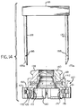
- FIG. 1 illustrates an invert arm assembly according to the present invention, which is generally identified by reference numeral 20.
- the invert arm assembly 20 is made up of side-by-side invert arm segments 22, 24.
- the invert arm segments 22, 24 are separable to open a space therebetween, as is known in the art, but when closed, as shown, define apertures 26 for receiving neck ring assemblies that must be removable from the invert arm assembly 20.
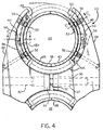
- the invert arm assembly 20 is shown in FIG. 4 with a neck ring assembly 28 installed in the radially outermost of the apertures 26, and it is to be understood that similar neck ring assemblies 28 will be installed in the other apertures 26 of the invert arm assembly 20 during the operation of an I.S.
- the invert arm assembly 20 is shown as having three apertures 26, and it is, therefore, designed for use with a triple gob I.S. machine, that is, a machine that is capable of forming three glass containers at a time at each machine section, as is also understood in the art.
- the design of the invert arm assembly 20 can be adapted for use in double gob I.S. machines, that is, machines capable of forming two glass containers at a time at each machine section, or in quad I.S. machines, that is, machines capable of forming four glass containers at a time at each machine section.
- one of the invert arm segments 22, 24, shown as the invert arm segment 22 is provided with an opening 30, and a pin 32 is inserted in the opening 30, the pin 32 being provided with a collar 34 (FIG. 7) to limit the depth of the insertion of the pin 32 into the opening 30.
- the other of the invert arm segments 22, 24, shown as the invert arm segment 34 is provided with an opening 36 that is aligned with the opening 30 when the invert arm segments 22, 24 are properly aligned.
- the free end of the pin 32 is slidably received within the opening 36 as the invert arm segments 22, 24 open and close with respect to one another to ensure the invert arm segments remain in proper alignment with one another.
- the opening 36 is lined with a generally T-shaped annular bushing 37 to facilitate the sliding of the free end of the pin 32 with respect to the opening 36.
- the neck ring assembly 28 is made up of a pair of semi-circular neck ring segments 38, 40, which are joined end to end in a circular configuration, as is shown in FIG. 4, when the invert arm segments 22, 24 are closed with respect to one another. In this position of the neck ring segments 38, 40, the neck ring assembly 28 is capable of molding a finish on a glass container being formed and of grasping the container being formed during its transfer by a 180° inverting motion in a vertical plane from the blank mold station to the blow mold station of an I.S. glass forming machine.
- the neck ring assembly 20 is also provided with an internal annular member 42 (FIG.
- the neck ring segments 38, 40 are provided with diametrically opposed, radially outwardly projecting flanges 44, 46, which are circumferentially spaced apart from one another, and the invert arm segments 22, 24, are provided with a diametrically opposed pair of circumferentially spaced apart radially inwardly projecting flanges 48, 50, respectively, surrounding each of the apertures 26.
- the spacing between the ends of the flanges 48, 50 is sufficient to permit a neck ring assembly 28 to be inserted into an aperture 26 when the flanges 44, 46 of the neck ring assembly 28 are properly aligned, that is, at right angles to their normal positions during the operation of the invert arm assembly 20 in an I.S. machine.
- the normal operating positions of the neck ring segments 38, 40 are shown in FIG. 4 at the 3 o'clock and 9 o'clock positions, respectively, and the positions of the flanges 44, 46 of the neck ring segments 38, 40 during insertion of a neck ring assembly 28 into the aperture 26, or during removal of the neck ring assembly 28 from the aperture 26, are shown in phantom in FIG. 4, at the 12 o'clock and 6 o'clock positions.
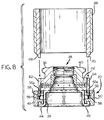
- Each of the invert arm segment flanges 48, 50 is generally T-shaped, with a radially innermost head portion, as is shown in FIG. 6 for the invert arm segment flange 50 of the invert arm segment 24, and each neck ring segment flange 44, 46 is generally C-shaped, as is shown in FIG. 6 for the neck ring segment 46.
- the head portion of each invert arm segment flange is received within an opening of a neck ring segment flange, as is shown in FIG. 6 where the head portion of the T-shaped invert arm segment flange 50 is received within an opening of the C-shaped neck ring segment 46, to positively axially position the neck ring segments 38, 40 with respect to the adjacent invert arm segments 22, 24.
- each of the invert arm segment flanges 48, 50 is provided with one or more, shown as two, centering pins 52 (FIGs. 4 and 6).
- Each centering pin 52 is provided with an enlarged rounded radially innermost end portion 52a, and is resiliently biased into contact with an adjacent portion of a neck ring assembly 28 by a coil spring 54.
- the coil spring 54 is trapped between the head portion 52a of the centering pin 52 and an inwardly projecting annular portion of the invert arm segment flange, shown as the portion 50a of the invert arm segment flange 50 in FIG. 6.
- each locking pin 56 projects upwardly beyond the shank portion of each of the T-shaped invert arm segment flanges 48, 50 with which it is associated, and is resiliently biased toward its uppermost position by a coil spring 58 that is trapped between a collar 60 secured to the locking pin 56 and a shoulder within a bore in the invert arm segment flange in which locking pin 56 is positioned.
- a coil spring 58 that is trapped between a collar 60 secured to the locking pin 56 and a shoulder within a bore in the invert arm segment flange in which locking pin 56 is positioned.
- FIG. 5 for the locking pin 56 associated with the invert arm segment flange 48, in which the coil spring 58 is located in a bore 48a of the invert arm segment flange 48 and engages a shoulder 48b of the bore 48a.
- the neck ring assembly 28 is normally prevented from turning within the aperture 26 in which it is located by providing the neck rings segments 38, 40 with slots 62, 64, respectively, in alignment with the locking pins 56, the free ends 56a of the locking pins 56 projecting into the slots 62, 64.
- the neck ring assembly 28 can be rotated to a sufficient extent to permit the neck ring segment flanges 44, 46 to align with the spaces between the ends of the invert arm segment flanges 48, 50, to thereupon permit the neck ring assembly 28 to be readily withdrawn from the aperture 26.
- an annular tool 66 with a spaced apart pair of downwardly depending fingers 68, 70 that align with the slots 62, 64, respectively, is provided to permit manual depression of the locking pins 56, as is shown in FIG. 9.
- elements that correspond to elements of the embodiment of FIGs. 1-9 are identified by three digit reference numerals, the last two digits of which correspond to the two digit numerals of the corresponding element of the embodiment of FIGs. 1-9.
- FIG. 10 illustrates an invert arm assembly, generally identified by reference numeral 120.
- the invert arm assembly 120 is made up of side-by-side invert arm segments 122, 124.
- the invert arm segments 122, 124 are separable to open a space therebetween, but when closed, as shown, define apertures 126 for receiving neck ring assemblies that must be removable from the invert arm assembly 120.
- the invert arm assembly 120 is shown in FIG. 14 with a neck ring assembly 128 installed in an aperture 126, and it is to be understood that similar neck ring assemblies 128 will be installed in the other apertures 126 of the invert arm assembly 120 during the operation of an I.S. glass container forming machine having invert arm assemblies corresponding to the invert arm assembly 120.
- one of the invert arm segments 122, 124 is provided with an opening 130, and a pin 132 is inserted in the opening 130, the pin 132 being provided with a collar 134 that limits the depth of the insertion of the pin 132 into the opening 130.
- the other of the invert arm segments 122, 124, shown as the invert arm segment 124 is provided with an opening 136 that is aligned with the opening 130 when the invert arm segments 122, 124 are properly aligned.
- the free end of the pin 132 is slidably received with the opening 136 as the invert arm segments 122, 124 open and close with respect to one another to ensure that the invert arm segment 122, 124 remain in proper alignment with one another, the opening 136 being provided with a generally T-shaped annular bushing 137 to facilitate the sliding of the free end of the pin 132 with respect to the opening 136.
- the neck assembly 128 is made up of a pair of semi-circular neck ring segments 138, 140, which are joined end to end in a circular figuration as is shown in FIG. 14, when the invert arm segment 122, 124 are closed with respect to one another, to permit the neck ring assembly 128 to mold a finish on a glass container being formed and to grasp the container being formed during its transfer, by a 180° inverting motion in a vertical plane, from the blank mold station to the blow mold station of an I.S. glass forming machine.
- the neck ring assembly 128 is also provided with an internal guide ring 142 that is endless in configuration and the guide ring 142 serves to guide the neck ring segments 138, 140 as they open and close with respect to one another.
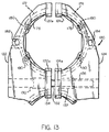
- the neck ring segments 138, 140 are provided with a diametrically opposed pair of outwardly facing arcuate slots 172, 174, respectively, and the invert arm segments 122, 124 are provided with arcuate shoes 176, 178, respectively, that are receivable in the slots 172, 174, respectively, to securely but disengageably retain the neck ring assembly 128 in an aperture 126 of the invert arm assembly 120.
- the shoes 176, 178 are biased toward their innermost positions by springs 180 (FIG. 13) to securely retain a neck ring assembly 128 in the aperture 126.
- the shoes 176, 178 can be retracted from their neck ring assembly retaining positions of FIG. 14 to positions shown in FIG.
- a hand tool 166 is provided to retract the spring-biased arcuate shoes 176, 178 to permit a neck ring assembly 128 to be withdrawn from, or inserted into, an aperture 126.
- the hand tool 166 is provided with a spaced apart pair of depending prongs 168, 170, each of which has a free end 168a, 170a, respectively, which it is tapered outwardly as it proceeds upwardly.
- the free ends 168a, 170a of the depending prongs 168, 170 are receivable in apertures 182, 184 of the shoes 176, 178, respectively, that are partly blocked by the invert arm segments 122, 124, respectively, when the shoes 176, 178 are in their innermost positions, as shown in FIGs. 13 and 14.
- the prongs 168, 170 are provided with radially outwardly projecting pins 186, 188, respectively, that will engage the invert arm segments 122, 124, respectively when the shoes 176, 178 have been radially retracted a distance sufficient to permit a neck ring assembly 128 to be removed from the aperture 126.
- the neck ring assembly 128 is provided with a diametrically opposed pair of longitudinally extending slots 190, only one of which is illustrated in FIG. 14.
- the slots 190 engage keys 192 in each aperture 126 of FIG. 10, the keys 192 being formed from adjacent portions 122a, 124a of the invert arm segments 122, 124, respectively, when the invert arm segments 122, 124 are in proximity to one another.
- the adjacent portion 122a, 124a serve to prevent the removal of the neck ring assembly 128 from, and the insertion of a neck ring assembly 128 into, an aperture 126 when the invert arm segments 122, 124 are spaced apart from one another, as they will be at the blow mold side of an I.S. machine during removal of finished containers from the neck ring assembly 128.
- elements that correspond to elements of the embodiment of FIGs. 1-9 and/or to the embodiment of FIGs.10-15 are identified by a three hundred (300) series numeral, the last two (2) digits of which correspond to the two (2) digit numerals of the corresponding elements of the embodiment of FIGs. 1-9 or to the last two (2) digits of the numerals of the corresponding elements of the embodiment of FIGs. 10-15.
- FIG. 16 shows a plurality of neck ring assemblies 328 installed in apertures 326 of an invert arm assembly 320, which is made up of an opposed pair of invert arm segments 322, 324.
- Each neck ring assembly 328 is made up of a pair of semi-circular neck ring segments 338, 340, each of whose opposed ends is positioned adjacent to an opposed end of the other neck ring segment, and the junctures between the segments 338, 340 of the neck ring assemblies 328 are aligned in the operating positions of the neck ring assemblies 328, as shown in FIG. 16.
- the segments 338, 340 of the neck ring assemblies 328 are provided with flattened portions 338a, 340a, respectively, on opposed sides of the junctures therebetween, for a purpose which will hereinafter to be described more fully.
- the invert arm segments 322, 324 are provided with a diametrically opposed pair of generally C-shaped, inwardly facing shoes 396 surrounding each of the apertures 326.
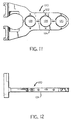
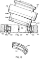
- One of the shoes 396 is shown in detail in perspective in FIG. 17.
- Each shoe 396 is secured to adjacent structure of the invert arm segment 322 or 324 in which it is installed by pins (not shown) extending through a spaced apart pair of holes 398, 399, and each is provided with a leaf spring 397 whose opposed ends are restrained by the shoe 396.
- the springs 397 are free to flex inwardly with respect to the shoes 396 as shown, for example, in FIGs. 20 and 22.
- the shoes 396 are spaced between a diametrically opposed pair of outwardly projecting flanges 328a, 328b of a neck ring assembly 328 as the neck ring assembly 328 is being installed in an aperture 326, or as it is being removed from an aperture 326, during which time the neck ring assembly 328 is oriented at a right angle around its central axis with respect to its normal operating position, as can be seen by a comparison of FIGs. 20 and 22.
- the spring 397 of an opposed pair of shoes 396 engages part-cylindrical portions of the neck ring segments 338, 340a in the operating position of each of the neck ring assemblies 328 to positively center each neck ring assembly 328 in the aperture 326 in which it is installed.
- the flat portions 338a, 340a of the neck ring segments 338, 340 readily permit a neck ring assembly 328 to be inserted into, or removed from, an aperture 326, when the neck ring assembly 328 is oriented at a right angle with respect to its normal operating position.
- Each neck ring assembly 328 is restrained against movement along its central axis in its normal operating position, at its lowermost position in the orientation shown in FIG. 17, by engagement of an annular shoulder 328c of the neck ring assembly 328 against an annular shoulder portion 396a of the shoe 396 and, at its uppermost position, by interference between the shoe 396 and the flanges 328a, 328b of the neck ring assembly 328. Further, each neck ring assembly 328 is releasably restrained against movement around its central axis in its normal operating position by retracting the shoe 396 along the axis of the holes 398, 399 by inserting the prongs of a hand tool similar to the hand tool 166 of the embodiment of FIGs. 10-15 into an aperture 382 of each of an opposed pair of shoes 396.
- FIGs. 16-22 The advantage of the embodiment of FIGs. 16-22 over the embodiments of FIGs. 1-9 or 10-15 is that the embodiment of FIGs. 16-22 is not as subject to being fouled with mold dope in glass forming machines whose forming molds are periodically swabbed with mold dope for purposes of facilitating the separation of the containers being formed therein from the structure of the molds.
Landscapes
- Engineering & Computer Science (AREA)
- Chemical & Material Sciences (AREA)
- Manufacturing & Machinery (AREA)
- Materials Engineering (AREA)
- Organic Chemistry (AREA)
- Specific Conveyance Elements (AREA)
- Re-Forming, After-Treatment, Cutting And Transporting Of Glass Products (AREA)
- Filling Of Jars Or Cans And Processes For Cleaning And Sealing Jars (AREA)
Abstract
Description
Claims (15)
- An invert arm assembly (20) for a glass container forming machine, said invert arm assembly comprising:an opposed pair of invert arm segments (22, 24), said invert arm segments being aligned with one another and being movable with respect to one another from positions where said invert arm segments are adjacent to one another to positions where said invert arm segments are separated from one another, said invert arm segments defining an aperture (26) for receiving and retaining a neck ring assembly (28) when said invert arm segments (22, 24) are disposed adjacent to one another, said invert arm segments being oscillatable in unison through an arc of approximately 180°;a neck ring assembly (28) disposed in said aperture (26), said neck ring assembly being retained by said invert arm segments (22, 24) when said invert arm segments are disposed adjacent to one another and being oscillatable with said invert arm segments when said invert arm segments are oscillated; andmeans for disengagably securing said neck ring assembly (28) to said invert arm segments (22, 24) within said aperture (26) to permit said neck ring assembly to be removed from said aperture while said invert arm segments are disposed adjacent to one another.
- An invert arm assembly according to claim 1 wherein said means for disengagably securing comprises:an opposed pair of arcuate shoes (176, 178) carried by said invert arm segments (122, 124), said opposed pair of arcuate shoes being movably transversely of said aperture (126) between readially innermost positions and radially outermost positions and releasably engaging said neck ring assembly (128) in the radially innermost positions of said arcuate shoes (176, 178); andspring means (180) resiliently biasing said pair of arcuate shoes (176, 178) toward their radially innermost positions.
- An invert arm assembly according to claim 2 whereinsaid neck ring assembly (128) comprises circumferentially extending slot means (172, 174), said pair of arcuate shoes (176, 178) of said means for disengagably securing being engaged in said circumferentially extending slot means when said pair of arcuate shoes are in their radially innermost positions and not being engaged in said circumferentially extending slot means when said pair of arcuate shoes are in their radially outermost positions.
- An invert arm assembly according to claim 2 and further comprising:means for circumferentially orienting said neck ring assembly within said at least one aperture.
- An invert arm assembly according to claim 4 wherein said means for circumferentially orienting comprises:an opposed pair of axially extending slots (190) in said neck ring assembly; andan opposed pair of keys (192) defined by said opposed pair of invert arm segments, said opposed pair of keys being receivable within said opposed pair of axially extending slots (190) when said opposed pair of invert arms segments are disposed adjacent to one another.
- An invert arm assembly according to claim 1 and further comprising:a pin (32) carried by one of said opposed pair of invert arm segments and projecting outwardly therefrom toward the other of said opposed pair of invert arm segments; andan opening (36) in the other of said opposed pair of invert arm segments, said pin (32) being slidably received in said opening (36) to maintain alignment between said opposed pair of invert arm segments (22, 24) as they move with respect to one another.
- An invert arm assembly according to claim 3 wherein each of said pair of arcuate shoes (176, 178) comprises:_an aperture (182, 184) extending transversely of said circumferentially extending slot means (172, 174), said aperture (182, 184) being engagably by a hand tool (166) from a location external to said invert arm segment to wedge said each of said arcuate shoes toward its radially outermost position.
- An invert arm assembly according to claim 1 wherein said means for disengagably securing comprises:an externally facing longitudinally extending slot (62, 64) in an exterior of said neck ring assembly (28);a pin (56) carried by one of said invert arm segments (22, 24), said pin having a free end engagable in said externally facing slot (62, 64) to prevent rotation of said neck ring assembly (28) within said aperture (26) of said invert arm assembly (20); andspring means (58) for resiliently biasing said pin (56) toward said neck ring assembly to cause the free end of said pin to project into said externally facing slot (62, 64) to prevent rotation of said neck assembly, said pin being engagable by a hand tool (66) from a location external to said invert arm assembly to cause said pin to become disengaged from said slot, to thereby permit said neck ring assembly to be rotated within said aperture.
- An invert arm assembly according to claim 1 wherein said means for disengagably securing comprises:an opposed pair of externally facing slots (62, 64) in an exterior of said neck ring assembly,an opposed pair of pins (56), one of said opposed pair of pins being carried by one of said invert arm segments, the other of said opposed pair of pins being carried by the other of said invert arm segments, each of said opposed pair of pins having a free end, the free end of one of said opposed pair of pins being receivable in one of said opposed pair of externally facing slots, the free end of the other of said opposed pair of pins being simultaneously receivable in the other of said opposed pair of externally facing slots, anda pair of springs (58), one of said pair of springs resiliently biasing one of said pair of pins toward said neck ring assembly to cause the free end of said one of said pair of springs to project into one of said externally facing slots of said neck ring assembly, the other of said pair of spring resiliently biasing the free end of the other of said pair of pins to cause the free end of said other of said pair of pins to project into the other of said pair of externally facing slots, each of said pair of pins being simultaneously engagable by a hand tool from a location external to said invert arm assembly to cause said pair of pins to become disengaged from said pair of slots, to thereby permit said neck ring assembly to be rotated within said aperture.
- An invert arm assembly according to claim 8 wherein said means for disengagably securing said neck ring assembly to said invert arm segments within said aperture further comprises:means for preventing axial motion of said neck ring assembly within said aperture when the free end of said pin is engaged in said externally facing slot (62, 64), and for permitting axial motion of said neck ring assembly within said aperture when the free end of said pin is not engaged in said externally slot and said neck ring assembly has been rotated within said aperture.
- An invert arm assembly according to claim 9 wherein said means for disengagably securing said neck ring assembly to said invert arm segments within said aperture further comprises:means for preventing axial motion of said neck ring assembly (28) within said aperture when the free end of each of said pair of pins (56) is engaged in an externally facing slot (62, 64) of said pair of externally facing slots, and for permitting axial motion of said neck ring assembly (28) within said aperture (26) when the free end of each of said pair of pins (56) is not engaged in an externally facing slot (62, 64) of said externally facing slots and said neck rings assembly has been rotated by a part of a turn within said aperture.
- An invert arm assembly according to claim 1 wherein said means comprises an opposed pair of generally C-shaped shoes (176, 178) carried by said invert arm segments (122, 124), each of said shoes engaging opposed ends of a recilient, arcuate spring (180) therein said arcuate spring resiliently engaging an exterior portion of said neck ring assembly.
- The method of changing a neck ring assembly (28) carried in an invert arm assembly (20) of a glass container forming machining of the individual section type, the invert arm assembly (20) having an opposed pair of invert arm segments (22, 24) that are aligned with one another and are movable with respect to one another and define an aperture (26) when the invert arm segments are disposed adjacent to one another, said method comprising:providing at least one of the neck ring segments (22, 24) with an externally engagable spring-biased means (58) for locking said neck ring assembly (28) in said aperture (26) when said spring-biased means is not engaged;engaging the spring-biased means (58) to unlock the neck ring assembly (28) from the aperture defined by the invert arm segments when the invert arm segments are disposed adjacent to one another; andremoving the neck assembly (28) from the aperture (26) while the invert arm segments (22, 24) are disposed adjacent to one another.
- The method of claim 13 wherein the neck ring assembly (28) is removed from the aperture (26) by a pulling motion.
- The method of claim 13 wherein the neck ring assembly (28) is removed from the aperture (26) by turning the neck ring assembly a part turn within the aperture (26) and then by pulling the neck ring assembly away from the aperture.
Applications Claiming Priority (2)
| Application Number | Priority Date | Filing Date | Title |
|---|---|---|---|
| US960455 | 1997-10-29 | ||
| US08/960,455 US5893942A (en) | 1997-10-29 | 1997-10-29 | Quick change invert arm assembly |
Publications (2)
| Publication Number | Publication Date |
|---|---|
| EP0915063A2 true EP0915063A2 (en) | 1999-05-12 |
| EP0915063A3 EP0915063A3 (en) | 1999-08-25 |
Family
ID=25503172
Family Applications (1)
| Application Number | Title | Priority Date | Filing Date |
|---|---|---|---|
| EP98120441A Withdrawn EP0915063A3 (en) | 1997-10-29 | 1998-10-29 | Quick change invert arm assembly |
Country Status (2)
| Country | Link |
|---|---|
| US (1) | US5893942A (en) |
| EP (1) | EP0915063A3 (en) |
Cited By (1)
| Publication number | Priority date | Publication date | Assignee | Title |
|---|---|---|---|---|
| WO2006073657A1 (en) | 2005-01-03 | 2006-07-13 | Owens-Brockway Glass Container Inc. | Guiding device for neck ring of a glassware making machine |
Families Citing this family (8)
| Publication number | Priority date | Publication date | Assignee | Title |
|---|---|---|---|---|
| US6318129B1 (en) * | 1999-12-14 | 2001-11-20 | Emhart Glass S.A. | Mold for use in I.S. machine |
| US6902708B1 (en) | 2000-04-25 | 2005-06-07 | Air Liquide America Corporation | Method and apparatus for making carbon black |
| US6848273B2 (en) * | 2002-06-03 | 2005-02-01 | Owens-Brockway Glass Container Inc. | Apparatus for blowing and removing glass containers |
| US7065986B2 (en) * | 2002-11-19 | 2006-06-27 | Eastman Kodak Company | Molding assembly |
| US7296442B2 (en) * | 2004-07-15 | 2007-11-20 | Owens-Brockway Glass Container Inc. | Neck ring cooling |
| US10000405B2 (en) * | 2010-06-29 | 2018-06-19 | Owens-Brockway Glass Container Inc. | Stelvin/cork glass wine bottles |
| EP2897873B1 (en) * | 2012-09-19 | 2019-09-25 | Vetropack Holding AG | Bottle opening for twist-off crown cap with splintering protection |
| EP3741732B1 (en) * | 2019-05-21 | 2024-02-21 | Emhart Glass S.A. | Glass forming machine comprising a swabbing station and method |
Family Cites Families (10)
| Publication number | Priority date | Publication date | Assignee | Title |
|---|---|---|---|---|
| US2949701A (en) * | 1955-09-14 | 1960-08-23 | Owens Illinois Glass Co | Apparatus for aligning glass forming molds |
| US3024571A (en) * | 1957-07-25 | 1962-03-13 | Owens Illinois Glass Co | Apparatus for molding glass |
| US3241941A (en) * | 1957-07-25 | 1966-03-22 | Owens Illinois Glass Co | Neck mold apparatus for glass forming machine |
| US3249418A (en) * | 1960-11-25 | 1966-05-03 | Owens Illinois Inc | Air operated neck molds |
| US3244499A (en) * | 1962-08-17 | 1966-04-05 | Corning Glass Works | Axially separable neck ring mold assembly |
| US3233999A (en) * | 1962-09-05 | 1966-02-08 | Owens Illinois Glass Co | Invert mechanism on glass forming machine |
| US3445218A (en) * | 1964-07-14 | 1969-05-20 | Owens Illinois Inc | Parison transfer and invert mechanism |
| US3617233A (en) * | 1969-05-08 | 1971-11-02 | Owens Illinois Inc | Glass-forming machine |
| US3934998A (en) * | 1974-06-26 | 1976-01-27 | Emhart Corporation | Neck ring cartridge for glassware machine |
| GB1597296A (en) * | 1978-03-17 | 1981-09-03 | Emhart Ind | Glassware forming machines |
-
1997
- 1997-10-29 US US08/960,455 patent/US5893942A/en not_active Expired - Fee Related
-
1998
- 1998-10-29 EP EP98120441A patent/EP0915063A3/en not_active Withdrawn
Cited By (5)
| Publication number | Priority date | Publication date | Assignee | Title |
|---|---|---|---|---|
| WO2006073657A1 (en) | 2005-01-03 | 2006-07-13 | Owens-Brockway Glass Container Inc. | Guiding device for neck ring of a glassware making machine |
| US7353667B2 (en) | 2005-01-03 | 2008-04-08 | Owens-Brockway Glass Container Inc. | Neck ring guide for glassware making machine |
| EP2246308A2 (en) | 2005-01-03 | 2010-11-03 | Owens-Brockway Glass Container Inc. | Guiding device for neck ring of a glassware making machine |
| EP2246308A3 (en) * | 2005-01-03 | 2011-10-26 | Owens-Brockway Glass Container Inc. | Guiding device for neck ring of a glassware making machine |
| KR101246000B1 (en) * | 2005-01-03 | 2013-03-20 | 오웬스-브로크웨이 글라스 컨테이너 인코퍼레이티드 | Guiding device for neck ring of a glassware making machine |
Also Published As
| Publication number | Publication date |
|---|---|
| US5893942A (en) | 1999-04-13 |
| EP0915063A3 (en) | 1999-08-25 |
Similar Documents
| Publication | Publication Date | Title |
|---|---|---|
| US5893942A (en) | Quick change invert arm assembly | |
| EP0945240B1 (en) | Segmented mold for pneumatic tires | |
| CN113977915B (en) | Preform conveying system with rotator angle indexing device | |
| EP2202048B1 (en) | Blowmould with locking device and the method | |
| JP2008023706A (en) | Individual support device for container with neck and equipment provided with transfer device using such support device | |
| US6428302B1 (en) | Universal blow mold assembly | |
| US5980810A (en) | Tire mold | |
| US11529757B2 (en) | Device for gripping a container preform, comprising an ejector acting as a tool for removing a spinner tip | |
| CN100513135C (en) | Arrangement for detachably fixing a stretching rod on a slide | |
| EP3293156A1 (en) | Neck ring holder device for machines for forming glass containers and method for manufacturing such containers | |
| EP1358025A1 (en) | Quick change connector for plunger for glass container forming process and equipment | |
| EP0997443A2 (en) | Neck ring mechanism for glass forming machine | |
| JP2010149460A (en) | Replacing method of preform conveying plug, blow molding machine, and preform conveying plug | |
| JP2002254433A (en) | Tire vulcanizing mold and tire manufacturing method | |
| US10138152B2 (en) | Lock ring mounting arrangement for blow heads | |
| US2328662A (en) | Transfer ring for molding purposes | |
| US7353667B2 (en) | Neck ring guide for glassware making machine | |
| US6450795B1 (en) | Quick change mounting apparatus at the eject station of an injection stretch blow molding machine | |
| US6210082B1 (en) | Method for repairing diametral surfaces of glass manufacturing molds | |
| US6085552A (en) | Aligning fixture for mold opening and closing mechanism | |
| CN113754250B (en) | Single-drip pliers | |
| US3792991A (en) | Machine for the production of hollow glass bodies | |
| AU2015228995B2 (en) | Lock re-pinning assembly | |
| CN217019453U (en) | Processing frock of elasticity opening snap ring and relief valve adjusting ring round pin | |
| RU2064852C1 (en) | Matrix for turret-type automatic die |
Legal Events
| Date | Code | Title | Description |
|---|---|---|---|
| PUAI | Public reference made under article 153(3) epc to a published international application that has entered the european phase |
Free format text: ORIGINAL CODE: 0009012 |
|
| AK | Designated contracting states |
Kind code of ref document: A2 Designated state(s): AT BE CH DE DK ES FI FR GB GR IT LI NL PT SE |
|
| AX | Request for extension of the european patent |
Free format text: AL;LT;LV;MK;RO;SI |
|
| PUAL | Search report despatched |
Free format text: ORIGINAL CODE: 0009013 |
|
| AK | Designated contracting states |
Kind code of ref document: A3 Designated state(s): AT BE CH CY DE DK ES FI FR GB GR IE IT LI LU MC NL PT SE |
|
| AX | Request for extension of the european patent |
Free format text: AL;LT;LV;MK;RO;SI |
|
| RIC1 | Information provided on ipc code assigned before grant |
Free format text: 6C 03B 9/16 A, 6C 03B 9/193 B, 6C 03B 9/34 B, 6C 03B 9/353 B |
|
| 17P | Request for examination filed |
Effective date: 19991204 |
|
| AKX | Designation fees paid |
Free format text: AT BE CH DE DK ES FI FR GB GR IT LI NL PT SE |
|
| 17Q | First examination report despatched |
Effective date: 20010919 |
|
| GRAH | Despatch of communication of intention to grant a patent |
Free format text: ORIGINAL CODE: EPIDOS IGRA |
|
| GRAH | Despatch of communication of intention to grant a patent |
Free format text: ORIGINAL CODE: EPIDOS IGRA |
|
| STAA | Information on the status of an ep patent application or granted ep patent |
Free format text: STATUS: THE APPLICATION IS DEEMED TO BE WITHDRAWN |
|
| 18D | Application deemed to be withdrawn |
Effective date: 20030304 |