EP0914581B1 - Solar energy receiver assembly - Google Patents
Solar energy receiver assembly Download PDFInfo
- Publication number
- EP0914581B1 EP0914581B1 EP97933364A EP97933364A EP0914581B1 EP 0914581 B1 EP0914581 B1 EP 0914581B1 EP 97933364 A EP97933364 A EP 97933364A EP 97933364 A EP97933364 A EP 97933364A EP 0914581 B1 EP0914581 B1 EP 0914581B1
- Authority
- EP
- European Patent Office
- Prior art keywords
- solar energy
- receiver
- energy
- diffuser
- assembly according
- Prior art date
- Legal status (The legal status is an assumption and is not a legal conclusion. Google has not performed a legal analysis and makes no representation as to the accuracy of the status listed.)
- Expired - Lifetime
Links
- 239000000463 material Substances 0.000 claims abstract description 24
- 239000012530 fluid Substances 0.000 claims description 8
- 229910010293 ceramic material Inorganic materials 0.000 claims description 5
- 238000009792 diffusion process Methods 0.000 claims description 5
- 239000011449 brick Substances 0.000 claims description 4
- 230000005855 radiation Effects 0.000 claims description 3
- 239000000919 ceramic Substances 0.000 claims description 2
- 230000001419 dependent effect Effects 0.000 claims description 2
- 239000011094 fiberboard Substances 0.000 claims description 2
- 238000009413 insulation Methods 0.000 claims description 2
- 239000007769 metal material Substances 0.000 claims description 2
- 238000001228 spectrum Methods 0.000 claims description 2
- 230000004907 flux Effects 0.000 abstract description 12
- 230000000694 effects Effects 0.000 abstract description 6
- 230000005611 electricity Effects 0.000 description 4
- 238000004519 manufacturing process Methods 0.000 description 4
- 230000005670 electromagnetic radiation Effects 0.000 description 3
- 239000002803 fossil fuel Substances 0.000 description 3
- 230000003287 optical effect Effects 0.000 description 3
- 238000013459 approach Methods 0.000 description 2
- 230000007613 environmental effect Effects 0.000 description 2
- 239000012528 membrane Substances 0.000 description 2
- PNEYBMLMFCGWSK-UHFFFAOYSA-N aluminium oxide Inorganic materials [O-2].[O-2].[O-2].[Al+3].[Al+3] PNEYBMLMFCGWSK-UHFFFAOYSA-N 0.000 description 1
- 210000003850 cellular structure Anatomy 0.000 description 1
- 238000006243 chemical reaction Methods 0.000 description 1
- 239000012141 concentrate Substances 0.000 description 1
- 235000012489 doughnuts Nutrition 0.000 description 1
- 239000003344 environmental pollutant Substances 0.000 description 1
- 239000000446 fuel Substances 0.000 description 1
- 239000011159 matrix material Substances 0.000 description 1
- 238000012986 modification Methods 0.000 description 1
- 230000004048 modification Effects 0.000 description 1
- 239000003758 nuclear fuel Substances 0.000 description 1
- 231100000719 pollutant Toxicity 0.000 description 1
- 238000010248 power generation Methods 0.000 description 1
- 239000010453 quartz Substances 0.000 description 1
- 230000001105 regulatory effect Effects 0.000 description 1
- 230000000717 retained effect Effects 0.000 description 1
- VYPSYNLAJGMNEJ-UHFFFAOYSA-N silicon dioxide Inorganic materials O=[Si]=O VYPSYNLAJGMNEJ-UHFFFAOYSA-N 0.000 description 1
- 230000003746 surface roughness Effects 0.000 description 1
- 230000005612 types of electricity Effects 0.000 description 1
Images

Classifications
-
- F—MECHANICAL ENGINEERING; LIGHTING; HEATING; WEAPONS; BLASTING
- F24—HEATING; RANGES; VENTILATING
- F24S—SOLAR HEAT COLLECTORS; SOLAR HEAT SYSTEMS
- F24S20/00—Solar heat collectors specially adapted for particular uses or environments
- F24S20/20—Solar heat collectors for receiving concentrated solar energy, e.g. receivers for solar power plants
-
- F—MECHANICAL ENGINEERING; LIGHTING; HEATING; WEAPONS; BLASTING
- F24—HEATING; RANGES; VENTILATING
- F24S—SOLAR HEAT COLLECTORS; SOLAR HEAT SYSTEMS
- F24S23/00—Arrangements for concentrating solar-rays for solar heat collectors
- F24S23/70—Arrangements for concentrating solar-rays for solar heat collectors with reflectors
-
- F—MECHANICAL ENGINEERING; LIGHTING; HEATING; WEAPONS; BLASTING
- F24—HEATING; RANGES; VENTILATING
- F24S—SOLAR HEAT COLLECTORS; SOLAR HEAT SYSTEMS
- F24S23/00—Arrangements for concentrating solar-rays for solar heat collectors
- F24S23/70—Arrangements for concentrating solar-rays for solar heat collectors with reflectors
- F24S2023/83—Other shapes
- F24S2023/832—Other shapes curved
-
- F—MECHANICAL ENGINEERING; LIGHTING; HEATING; WEAPONS; BLASTING
- F24—HEATING; RANGES; VENTILATING
- F24S—SOLAR HEAT COLLECTORS; SOLAR HEAT SYSTEMS
- F24S23/00—Arrangements for concentrating solar-rays for solar heat collectors
- F24S23/70—Arrangements for concentrating solar-rays for solar heat collectors with reflectors
- F24S2023/88—Multi reflective traps
-
- Y—GENERAL TAGGING OF NEW TECHNOLOGICAL DEVELOPMENTS; GENERAL TAGGING OF CROSS-SECTIONAL TECHNOLOGIES SPANNING OVER SEVERAL SECTIONS OF THE IPC; TECHNICAL SUBJECTS COVERED BY FORMER USPC CROSS-REFERENCE ART COLLECTIONS [XRACs] AND DIGESTS
- Y02—TECHNOLOGIES OR APPLICATIONS FOR MITIGATION OR ADAPTATION AGAINST CLIMATE CHANGE
- Y02E—REDUCTION OF GREENHOUSE GAS [GHG] EMISSIONS, RELATED TO ENERGY GENERATION, TRANSMISSION OR DISTRIBUTION
- Y02E10/00—Energy generation through renewable energy sources
- Y02E10/40—Solar thermal energy, e.g. solar towers
Definitions
- This invention is related to a solar energy receiver assembly for receiving solar energy from a solar energy concentrator.
- Utility companies are interested in not only being environmentally sensitive by using sources of renewable energy, such as solar energy, and avoiding the generation of pollutants associated with fossil fuel and nuclear power generation systems. They are also interested in reducing the costs associated with constructing, operating and eventually dismantling additional nuclear or fossil fuel powered electricity generating facilities. Fuel costs, particularly the costs of fossil fuels such as oil, have fluctuated wildly in the past and utility companies are interested in developing sources of energy that would not be subject to these price fluctuations. Fields of solar concentrators combined with Stirling cycle engines connected to electrical generators are being seriously considered for these types of electricity generation applications.
- the Stirling cycle engines and related devices for utilizing solar energy that could be used in connection with the inventive solar energy diffuser could include those previously developed by the Assignee of the present invention, Stirling Thermal Motors, Inc., including those described in U.S. patent nos. 4,707,990; 4,715,183, 4,785,633, and 4,911,144, which are hereby incorporated herein by reference.
- the solar concentrators must be constructed using reflectors that have relatively imperfect optical characteristics, such as mirrors formed by attaching the edges of a mirrorized membrane material to a rigid frame and drawing a vacuum on the back of the membrane to cause it to form a concave reflective surface.
- reflectors that have relatively imperfect optical characteristics, such as mirrors formed by attaching the edges of a mirrorized membrane material to a rigid frame and drawing a vacuum on the back of the membrane to cause it to form a concave reflective surface.
- Relatively perfect reflectors such as the laboratory grade mirrors used in telescopes, are far too expensive to be used in commercial solar collection systems.
- each facet of the reflector array has slightly different optical characteristics and can never be perfectly aligned with respect to the solar energy receiver, the solar energy concentrated onto the solar energy receiver by an array of reflector facets will necessarily be less uniform than an equivalently sized singe reflector.
- Environmental factors such as wind, and mechanical factors, such as material fatigue, can also dynamically change the distribution of the energy concentrated by the reflectors into the receiver.
- the receiver tubes which absorb the solar energy be as short as possible. Additional receiver tube length causes additional frictional energy losses and reduces the efficiency of the receiver system.
- the materials used to fabricate the tubes have inherent limitations, however, that limit the maximum amount of energy flux that the tubes can be subjected to without failing. While the temperatures of the tube walls are generally regulated by the working fluid circulated within the tubes, inadvertently high energy concentrations can cause "hot spots" that can lead to catastrophic tube failures.
- Solar reflectors are typically aligned with respect to the solar energy receivers so that the focal point of the reflector is located behind the receiver tubes.
- the expected concentration of solar energy in the vicinity of the receiver tubes in this configuration can be visualized as a doughnut or innertube shaped area of high energy flux. If the reflectors are not optically perfect or not properly positioned and aligned, hot spots (areas of inadvertently over-concentrated energy) can be formed. If the energy flux in one of these hot spots is sufficiency high, the tube material limitations can be exceeded and the tubes can fail.
- the inventive diffuser reduces the convective energy losses associated with open prior art solar receiver chambers because the cellular structure of the inventive diffuser restricts the exchange of hot air in the vicinity of the receiver tubes with cooler external air, particularly air exchange due to turbulence associated with the flow of air generally parallel to the aperture of the receiver.
- the additional heat retained within the receiver chamber results in increased efficiency of the solar receiver unit and the entire solar energy collection system incorporating the diffuser.
- a portion of the solar energy passing through energy diffusing cavities 26 is reflected on one or more occasions by cavity walls 30 and is emitted from the cavities through inner openings 28 with a different and more diffused orientation than it had when it entered the cavities.
- a portion of the solar energy 22 passing through energy diffusing cavities 26 does not contact cavity walls 30 and is unaffected by diffuser 10.
- solar energy 22 After being emitted from diffuser 10 at inner openings 28, solar energy 22 passes through the lower section of receiver chamber 20 and is substantially absorbed by receiver tubes 16.
- Working fluid circulated through receiver tubes 16 transfers solar energy 22 to a device that utilizes the energy, such as a Stirling cycle engine.
- raypaths 34 and 36 solar energy reflecting off the side of cavity walls 30 will be reoriented in two ways, either directionally or spatially. These cavitational reorientation effects serve to scatter and diffuse the incoming solar energy by disrupting the focused character of the solar energy received from the solar energy concentrator.
- the specular vs. diffusive reflective characteristics of the materials or materials which make up cavity walls 30 and the relative geometry of the energy diffusing cavities must be balanced to provide the desired degree of diffusion in the diffuser.
- the ability of the materials which will make up the diffuser to survive in the environment within receiver chamber 20 must also be considered. Long narrow cavities that have cavity walls that are highly diffusely reflective will diffuse substantially more of the incoming solar energy than short broad cavities that have cavity walls that are highly specularly reflective. It is also possible to select materials that exhibit wavelength dependent effects, such as materials which reflect the vast majority of the incident energy only in the wavelength spectrum of the incoming solar radiation (from .2 to 2.0 micrometers).
- the apparent emissivity of the cavity approaches the value of 1 which holds for a black body.
- An embodiment of diffuser 10 having a matrix of energy diffusing cavities which are approximately 10 millimeters across and 50 millimeters long is expected to produce a satisfactory diffusing effect and a uniform pattern of energy exiting the diffuser.
Landscapes
- Engineering & Computer Science (AREA)
- Physics & Mathematics (AREA)
- Life Sciences & Earth Sciences (AREA)
- Sustainable Development (AREA)
- Sustainable Energy (AREA)
- Thermal Sciences (AREA)
- Chemical & Material Sciences (AREA)
- Combustion & Propulsion (AREA)
- Mechanical Engineering (AREA)
- General Engineering & Computer Science (AREA)
- Photovoltaic Devices (AREA)
Abstract
Description
- This invention is related to a solar energy receiver assembly for receiving solar energy from a solar energy concentrator.
- Plans are under consideration at several utility companies to develop large fields of solar powered electrical generators to generate additional quantities of electricity needed during peak electrical demand periods Because peak demand periods for electrical service occur during daylight hours, when solar powered electrical generators are operable, and demands for electrical service are often substantially reduced at night, when solar powered electrical generators are inoperable, solar powered electrical generators offer an ideal source of electricity for utility companies to compensate for this daily fluctuation in electrical service demand.
- Utility companies are interested in not only being environmentally sensitive by using sources of renewable energy, such as solar energy, and avoiding the generation of pollutants associated with fossil fuel and nuclear power generation systems. They are also interested in reducing the costs associated with constructing, operating and eventually dismantling additional nuclear or fossil fuel powered electricity generating facilities. Fuel costs, particularly the costs of fossil fuels such as oil, have fluctuated wildly in the past and utility companies are interested in developing sources of energy that would not be subject to these price fluctuations. Fields of solar concentrators combined with Stirling cycle engines connected to electrical generators are being seriously considered for these types of electricity generation applications. The Stirling cycle engines and related devices for utilizing solar energy that could be used in connection with the inventive solar energy diffuser could include those previously developed by the Assignee of the present invention, Stirling Thermal Motors, Inc., including those described in U.S. patent nos. 4,707,990; 4,715,183, 4,785,633, and 4,911,144, which are hereby incorporated herein by reference.
- To cost effectively generate electricity on a commercial scale utilizing solar energy concentrators, solar energy receivers, Stirling cycle engines, and electrical generators in combination, the solar concentrators must be constructed using reflectors that have relatively imperfect optical characteristics, such as mirrors formed by attaching the edges of a mirrorized membrane material to a rigid frame and drawing a vacuum on the back of the membrane to cause it to form a concave reflective surface. Relatively perfect reflectors, such as the laboratory grade mirrors used in telescopes, are far too expensive to be used in commercial solar collection systems.
- Instead of manufacturing extremely large single reflectors, it is often more cost effective to assemble a collection of smaller reflectors (also called facets) into an array that simulate the reflective characteristics of a larger single reflector. This array of smaller reflectors collects the majority of the solar energy that could be collected by an equivalently sized singe reflector, but they are much easier to manufacture and maintain. Because each facet of the reflector array has slightly different optical characteristics and can never be perfectly aligned with respect to the solar energy receiver, the solar energy concentrated onto the solar energy receiver by an array of reflector facets will necessarily be less uniform than an equivalently sized singe reflector.
- Environmental factors, such as wind, and mechanical factors, such as material fatigue, can also dynamically change the distribution of the energy concentrated by the reflectors into the receiver.
- When designing and engineering a solar energy receiver, it is preferred that the receiver tubes which absorb the solar energy be as short as possible. Additional receiver tube length causes additional frictional energy losses and reduces the efficiency of the receiver system. The materials used to fabricate the tubes have inherent limitations, however, that limit the maximum amount of energy flux that the tubes can be subjected to without failing. While the temperatures of the tube walls are generally regulated by the working fluid circulated within the tubes, inadvertently high energy concentrations can cause "hot spots" that can lead to catastrophic tube failures.
- Solar reflectors are typically aligned with respect to the solar energy receivers so that the focal point of the reflector is located behind the receiver tubes. The expected concentration of solar energy in the vicinity of the receiver tubes in this configuration can be visualized as a doughnut or innertube shaped area of high energy flux. If the reflectors are not optically perfect or not properly positioned and aligned, hot spots (areas of inadvertently over-concentrated energy) can be formed. If the energy flux in one of these hot spots is sufficiency high, the tube material limitations can be exceeded and the tubes can fail. To compensate for the normal level of nonuniform flux distribution that would be expected under these circumstances and to prevent peak flux levels from causing the tube temperatures to exceed their designed material limits, a large safety margin between expected flux levels and tube material maximum allowable flux levels had to be built into prior art solar receivers. To provide this large safety margin, the receivers were placed well outside of the optimal focal distance of the reflectors, the receivers were contained within chambers which were larger than otherwise necessary to accommodate this less focused energy, and the receiver tube lengths were increased to allow them to capture more of this less focused solar energy. While these modifications addressed the hot spots/tube failures problem, it designed in significant inefficiencies into prior art solar energy receivers and the entire solar energy collection systems.
- Previous attempts to address this problem have focused on attempting to more precisely tune the reflectors to more closely regulate the energy flux seen by the receivers. While attempts to improve both the optical qualities of low cost reflectors and the ability to properly position and align these types of reflectors will obviously continue, the inventive diffuser takes the opposite approach. The diffuser receives the imperfectly focused solar energy collected by prior art solar collectors and diffuses the solar energy before it contacts the receiver. This allows the receiver to be designed with an expected flux level that is closer to the material limits of the receiver tube itself, which can dramatically improve the performance characteristics of solar collection systems using conventional solar energy concentrators.
- Another problem associated with conventional solar receiver units is the loss of energy associated with the circulation of air into and out of the receiver chamber. Solar energy receivers are typically located in a housing constructed of refractory bricks. The aperture through which the solar energy is received is generally narrower than the array of receiver tubes to limit the loss of energy out of the system.
- In some prior art solar energy receivers, quartz lens were placed over the aperture to limit the loss of energy associated with the circulation of air into and out of the receiver chamber. These types of lenses, however, are quite expensive and as they become dirty, less and less of the available light energy is able to pass into the receiver chamber and is instead absorbed by the contaminates, which can lead to the failure of the lens.
- It is known from WO-94/06046 an energy directing device for use with energy which has a wave-like propagation mode, said device comprising an array of reflecting elements, said array having a surface of curvature, the elements of the array being positioned with their reflecting surfaces substantially orthogonal to the surface of curvature.
- The inventive diffuser reduces the convective energy losses associated with open prior art solar receiver chambers because the cellular structure of the inventive diffuser restricts the exchange of hot air in the vicinity of the receiver tubes with cooler external air, particularly air exchange due to turbulence associated with the flow of air generally parallel to the aperture of the receiver. The additional heat retained within the receiver chamber results in increased efficiency of the solar receiver unit and the entire solar energy collection system incorporating the diffuser.
- Further objects, features and advantages of the invention will become apparent from a consideration of the following description and the appended claims when taken in connection with the accompanying drawings.
-
- FIG. 1 is a cross section view of a solar energy receiver incorporating the inventive diffuser;
- FIG. 2 is a perspective view of an embodiment of the inventive diffuser having energy diffusing cavities with hexagonal cross sections;
- FIG. 3 is a close up cross sectional view of one of the energy diffusing cavities of the inventive diffuser from FIG. 2 showing various demonstrative solar energy raypaths;
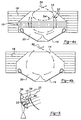
- FIGS. 4a and 4b are cross sectional views of two solar energy receivers, the first incorporating the inventive diffuser and the second without the inventive diffuser;
- FIG. 5 is a schematic view of a solar powered electrical generation system incorporating the inventive diffuser.
-
- A diffuser in accordance with this invention is shown installed in a solar energy receiver in FIG. 1 and is generally designated by
reference number 10. Diffuser 10 is installed in asolar energy receiver 12 between areceiver aperture 14 andreceiver tubes 16.Solar energy receiver 12 has refractory bricks orfiberboard type insulation 18 which surround and retain heat within areceiver chamber 20.Solar energy 22 enteringsolar energy receiver 12 throughreceiver aperture 14, passes through the upper portion ofreceiver chamber 20 and entersdiffuser 10 through a plurality ofouter openings 24. Fromouter openings 24,solar energy 22 passes through a plurality ofenergy diffusing cavities 26 and is emitted fromdiffuser 10 at a plurality ofinner openings 28. As will be discussed in more detail below, a portion of the solar energy passing throughenergy diffusing cavities 26 is reflected on one or more occasions bycavity walls 30 and is emitted from the cavities throughinner openings 28 with a different and more diffused orientation than it had when it entered the cavities. A portion of thesolar energy 22 passing throughenergy diffusing cavities 26 does not contactcavity walls 30 and is unaffected bydiffuser 10. After being emitted fromdiffuser 10 atinner openings 28,solar energy 22 passes through the lower section ofreceiver chamber 20 and is substantially absorbed byreceiver tubes 16. Working fluid circulated throughreceiver tubes 16 transferssolar energy 22 to a device that utilizes the energy, such as a Stirling cycle engine. - While
diffuser 10 may be located anywhere between the solar concentrator andreceiver tubes 16, it is preferable to placediffuser 10 as close as possible toreceiver tubes 16. This allows the solar concentrators to be focused as ifdiffuser 10 was not present. Diffuser 10 then diffuses the incomingsolar energy 22 to reduce the probability of inadvertently forming hot spots that could cause tube failures. The environment adjacent toreceiver tubes 16 is severe, however, being subjected to both extremely high temperatures and wide temperature variations. Becausediffuser 10 is not externally cooled, as arereceiver tubes 16 by the working fluid,diffuser 10 must be able to radiate significant quantities of heat to survive in this harsh operating environment. - FIG. 2 shows an embodiment of diffuser 10 from a perspective view.
Outer openings 24 and inner openings 28 (not shown) are hexagonally shaped andenergy diffusing cavities 26 have hexagonally shaped cross sections. This shape allows the individualenergy diffusing cavities 26 to be tightly bundled together withindiffuser 10 and reduces the required thickness ofcavity walls 30. Minimizing wall thickness is important because the portions ofcavity walls 30 which are perpendicular to the direction of incomingsolar energy 22 reflect solar energy away fromdiffuser 10 and the majority of this reflected energy will be emitted throughreceiver aperture 14 out ofsolar energy receiver 12 and lost. Minimizing the wall thickness is also important because it reduces the diffuser mass to surface area ratio which increases the ability of the diffuser to radiate heat. Bundled hexagonal shapes can also provide a great deal of structural strength to diffuser 10.Diffuser 10 will ideally be structurally self supporting and only connected to the remaining components ofsolar energy receiver 12 at its periphery, where the diffuser is mounted torefractory bricks 18.Diffuser 10 could alternatively be constructed of bundled tubes with circular, square or rectangular cross sections or a myriad of other alternative shapes to provide tightly bundled energy diffusing cavities. The commercial availability of engineering materials consistent with the disclosed embodiment, makes this a preferred commercial embodiment ofdiffuser 10. - While
cavity walls 30 are shown in FIGS. 1 and 2 to be perpendicular toreceiver aperture 14 and are shown to be uniformly parallel to one another, theinventive diffuser 10 is not restricted to these particular configurations. An alternative embodiment of the diffuser, for instance, could be constructed by determining the quantity of energy expected to enter each discreteenergy diffusing cavity 26 from the solar concentrator and its relative orientation and then varying the orientation ofcavity walls 30 to distribute this energy uniformly along the surfaces ofreceiver tubes 16. -
Diffuser 10 may be made of any material that is highly reflective ofsolar energy 22 and capable of surviving under the extreme environmental conditions withinsolar energy receiver 12. Suitable materials for constructingdiffuser 10 include ceramics and coated metal materials. Alumina-based ceramic materials fabricated into honeycomb sheet structures are believed to be the best commercially available material for the manufacturing the inventive diffuser. These types of ceramic materials can be highly reflective of incident solar energy and are also able to readily reradiate the solar energy absorbed by the diffuser. Honeycomb ceramic materials manufactured by Coming Incorporated, Coming, New York 14831 may have acceptable engineering specifications for the inventive diffuser. - In FIG. 3, a close up cross section view of an individual energy diffusing cavity is shown with a variety of demonstrative raypaths. The behavior of
solar energy 22 can effectively be represented by raypaths which are parallel to the direction of propagation. In FIG. 3, incomingsolar energy 22 entersenergy diffusing cavity 26 throughouter opening 24 and exitsenergy diffusing cavity 26 throughinner opening 28. A portion ofsolar energy 22 enteringenergy diffusing cavity 26 throughouter opening 24 is reflected bycavity walls 30 before it exitsenergy diffusing cavity 26 throughinner opening 28. As will be seen below, this reflected solar energy has a different and more diffuse orientation when it exitsenergy diffusing cavity 26 throughinner opening 28 than it had when it enteredenergy diffusing cavity 26 throughouter opening 24. -
Raypath 32 representssolar energy 22 which entersenergy diffusing cavity 26 throughouter opening 24 at a relative location withinouter opening 24 and at an incidence angle that allows it to pass throughenergy diffusing cavity 26 without contactingcavity walls 30. If thecavity walls 30 ofdiffuser 10 are perpendicular toouter opening 24, anysolar energy 22 which entersenergy diffusing cavity 26 perpendicularly toouter opening 24 will pass throughenergy diffusing cavity 26 without being reoriented or diffused. The proportion of thesolar energy 22 that will pass throughenergy diffusing cavity 26 unaltered is a function of the range of relative incidence angles of the energy enteringenergy diffusing cavity 26 and the geometry of the energy diffusing cavity. The greater the ratio is between the length ofenergy diffusing cavity 26 and the diameter ofouter opening 24, the lower the proportion ofsolar energy 22 that will pass throughenergy diffusing cavity 26 without being reoriented and diffused. - Raypath 34 represents
solar energy 22 which entersenergy diffusing cavity 26 throughouter opening 24 at a relative location withinouter opening 24 and at an incidence angle such thatsolar energy 22 reflects once off ofcavity wall 30 before exitingenergy diffusing cavity 26 throughinner opening 28. As can be seen from raypath 34, thesolar energy 22 emitted fromenergy diffusing cavity 26 for these types of raypaths has an inverted directional orientation compared to the directional orientation these types of raypaths had when they enteredenergy diffusing cavity 26. -
Raypath 36 representssolar energy 22 which entersenergy diffusing cavity 26 throughouter opening 24 at a relative location withinouter opening 24 and at an incidence angle such thatsolar energy 22 reflects twice off ofcavity wall 30 before exitingenergy diffusing cavity 26 throughinner opening 28. As can be seen from this raypath, thesolar energy 22 is emitted fromenergy diffusing cavity 26 at an orientation identical to that it had when it enteredenergy diffusing cavity 26, but the raypath has been spatially displaced relative to the incoming raypath. Obviously there are raypaths where the solar energy is reflected offcavity walls 30 on 3, 4 or more occasions before it is emitted fromenergy diffusing cavity 26. - As can be seen by
raypaths 34 and 36, solar energy reflecting off the side ofcavity walls 30 will be reoriented in two ways, either directionally or spatially. These cavitational reorientation effects serve to scatter and diffuse the incoming solar energy by disrupting the focused character of the solar energy received from the solar energy concentrator. - In demonstrating the effects of energy traveling along
raypaths 34 and 36, it was assumed thatsolar energy 22 will reflect specularly offcavity wall 30. Specular reflection is commonly referred to as mirror-like reflection, where the outgoing ray leaves the reflecting surface as a mirror image of the incoming ray. Specular reflection occurs when the surface is smooth compared to the wavelength of the incoming radiation (i.e. when the roughness of the surface is less than one-tenth of the wavelength of the reflected electromagnetic radiation). A second type of reflection, diffuse reflection, occurs when the surface roughness exceeds two times the wavelength of the electromagnetic radiation. When raypaths are diffusely reflected, the energy is reflected away from the surface in uniform hemispherical directions from the point of contact. -
Raypath 38 demonstrates the effects of diffuse reflection off the surface ofcavity wall 30. Whensolar energy 22 traveling alongraypath 38 is diffusely reflected bycavity wall 30, the energy is reflected away fromcavity wall 30 uniformly in all directions. A portion of the energy is reflected at angles where it will be directly emitted back out of the cavity, a portion of the energy is reflected at angles where it will directly passes through the cavity, and a portion of the energy is reflected at angles where the energy will reflect at least once more off a wall of the cavity before it leaves the cavity. A portion of the subsequently rereflected energy will eventually pass through the cavity and a portion will be emitted back out of the cavity. - As can be seen by
raypath 38,solar energy 22 which diffusely reflects off the side ofcavity walls 30 will be uniformly disoriented and will immediately lose any focused character. A portion of the diffusely reflected energy is reflected out of the diffuser, however, and is lost. -
Raypath 40 demonstrates the effects of a mixed reflection that has both specular and diffuse characteristics. Mixed reflections typically occur when the roughness of the surface is between one tenth and two times the wavelength of the reflected electromagnetic radiation. In these types of reflections, a portion of the energy is reflected in the general mirror image direction, although a portion of the energy is also reflected in a generally diffuse manner. - To design an optimal solar energy diffuser for any particular solar energy collection system, the specular vs. diffusive reflective characteristics of the materials or materials which make up
cavity walls 30 and the relative geometry of the energy diffusing cavities must be balanced to provide the desired degree of diffusion in the diffuser. The ability of the materials which will make up the diffuser to survive in the environment withinreceiver chamber 20 must also be considered. Long narrow cavities that have cavity walls that are highly diffusely reflective will diffuse substantially more of the incoming solar energy than short broad cavities that have cavity walls that are highly specularly reflective. It is also possible to select materials that exhibit wavelength dependent effects, such as materials which reflect the vast majority of the incident energy only in the wavelength spectrum of the incoming solar radiation (from .2 to 2.0 micrometers). - As the ratio of the length of energy diffusing cavity to the diameter of energy diffusing cavity increases, the apparent emissivity of the cavity approaches the value of 1 which holds for a black body. The doser the apparent emissivity of the cavity is to 1, the less of the energy passing into the diffuser which will eventually be reflected back through the diffuser. An embodiment of
diffuser 10 having a matrix of energy diffusing cavities which are approximately 10 millimeters across and 50 millimeters long is expected to produce a satisfactory diffusing effect and a uniform pattern of energy exiting the diffuser. - Because
diffuser 10 reorients and diffuses the incomingsolar energy 22, the likelihood of hot spots is reduced andsolar energy receiver 12 can be designed with expected energy flux levels which are much closer to the material limitations ofreceiver tubes 16. This allows the solar energy concentrators to be positioned where they will provide a more focused supply of solar energy into the solar energy receiver, and allow the size of bothreceiver chamber 20 andreceiver tubes 16 to be reduced to accept this more focused energy, which can dramatically increase the overall efficiency of the solar energy receiver and the entire solar energy collection system. - A second type of efficiency is also gained by use of the inventive diffuser. FIGS. 4a and 4b show the circulation of air within a solar energy
receiver incorporating diffuser 10 and a conventional open solar energy receiver without the inventive diffuser. In FIG. 4a, a generally cross aperture air current 50 passes throughreceiver aperture 14 and intoupper receiver chamber 20. As air current 50 circulates withinupper receiver chamber 20, anunbaffled portion 52 of the air current will pass through theenergy diffusing cavities 26 ofdiffuser 10, pass into the lower portion ofreceiver chamber 20, come into contact withreceiver tubes 16, and exit the lower portion ofreceiver chamber 20 through theenergy diffusing cavities 26. The otherbaffled portion 54 of air current 50 will be deflected along the upper surface ofdiffuser 10 and will not circulate into the lower portion ofreceiver chamber 20. The portion of the air current 50 that will be deflected bydiffuser 10 will depend on the wind velocity, the incidence angle of the air current as it contacts the diffuser, the geometry of each cavity and the relative smoothness or roughness of the material used to manufacture the diffuser. FIG. 4b shows a similar generally cross aperture air current 50 passing throughreceiver aperture 14 and intoreceiver chamber 20 whendiffuser 10 is not present. Because there is no physical restriction that would separate the upper portion ofreceiver chamber 20 from the lower portion of the receiver chamber, air current 50 tends to circulate generally along the outside of the receiver chamber, where it comes into contact withreceiver tubes 16 and then exits the receiver chamber throughreceiver aperture 14. Because the air circulating in the immediate vicinity ofreceiver tubes 16 removes energy from thesolar energy receiver 12 and the diffuser limits the amount of air circulating in this area, the inventive diffuser increases the efficiency of the solar energy receiver over prior open solar receivers. - FIG. 5 shows a typical solar energy to electrical energy conversion system incorporating the inventive diffuser. A
solar energy concentrator 56, consisting generally of a parabolic reflector having an array of parabolic reflector facets, concentrates solar energy intosolar energy receiver 12. The solar energy is absorbed by the receiver tubes and transferred to the working fluid. The working fluid is then circulated to aStirling cycle engine 58 which converts the heat energy into rotational mechanical energy. This rotational mechanical energy is converted by electrical generator 60 into electrical energy which can be transmitted to an electrical power distribution grid. As discussed above, the inventive diffuser allows optically imperfect cost effective reflectors to be focused more closely on the receiver tubes at expected flux levels that are doser to the material limits of the tubes, with less of a concern that unintended hot spots will be formed that could cause catastrophic tube failures, and, through the use of shorter tubes and more compact receiver housings, increasing the overall efficiency of the solar energy receiver. In addition, the diffuser baffles incoming air and reduces the energy losses associated with the exchange of air into and out of the receiver chamber. These increased efficiencies can dramatically increase the overall efficiency of the entire solar powered electrical generation system.
Claims (18)
- A solar energy receiver assembly for receiving solar energy from a solar energy concentrator (56), said solar energy receiver assembly characterized by:
a solar energy receiver (12) having an insulated receiver chamber (20) and an open receiver aperture (14) through which air and solar energy is allowed to enter said receiver chamber (20), means for absorbing solar energy (16) are fixed to said solar energy receiver (12) within said receiver chamber (20) and located opposite said receiver aperture (14), a diffuser (10) having a relatively thin, flat structure being located within said receiver chamber (20) between said receiver aperture (14) and said means for absorbing solar energy (16) and being positioned approximately parallel to said receiver aperture (14) thereby creating a lower section of said receiver chamber (20), said diffuser (10) having a plurality of open cavities (26), each of said cavities (26) having an outer opening (24), an inner opening (28), and side walls (30), said cavities (26) being positioned so said solar energy is received into said cavities from said solar energy concentrator (56) through said outer openings (24) and emitted from said cavities (26) to said means for absorbing solar energy (16) through said inner openings (28), said cavities (26) allowing air to pass, whereby restricting the circulation of air within said lower section of the receiver chamber (20) near said means for absorbing solar energy (16). - A solar energy receiver assembly according to Claim 1 characterized by said cavities (26) being tightly bundled.
- A solar energy receiver assembly according to Claim 1 characterized by said diffuser (10) being self supporting.
- A solar energy receiver assembly according to Claim 1 characterized by said diffuser (10) being formed from material highly reflective of solar energy or said diffuser (10) having an exterior surface and said exterior surface is formed from material highly and primarily specularly reflective of solar energy.
- A solar energy receiver assembly according to Claim 1 characterized by said energy diffusion cavities (26) having hexagon shaped cross sections.
- A solar energy receiver assembly according to Claim 1 characterized by said energy receiving means (16) further being characterized by heater tubes and working fluid circulating within said heater tubes.
- A solar energy receiver assembly according to Claim 1 characterized by said diffuser (16) means being formed from aluminia-based ceramic material.
- A solar energy receiver assembly according to Claim 1 characterized by the ratio of the average lenght of said side walls (30) divided by the average width of said outer openings (24) being between 1 and 7.
- A solar energy receiver assembly according to Claim 1 characterized by the ratio of the average length of said side walls (30) divided by the average width of said outer openings (24) being between 4 and 6.
- A solar energy receiver assembly according to Claim 1 characterized by said solar energy receiver (12) having refractory bricks or fiberboard type insulation (18) which surround and retain heat within said receiver chamber (20).
- A solar energy receiver assembly according to Claim 1 characterized by said energy diffusion cavities (26) having circular shaped cross sections.
- A solar energy receiver assembly according to Claim 1 characterized by said energy diffusion cavities (26) having square shaped cross sections.
- A solar energy receiver assembly according to Claim 1 characterized by said energy diffusion cavities (26) having rectangular shaped cross sections.
- A solar energy receiver assembly according to Claim 1 characterized by said diffuser (16) being formed from ceramics and/or coated metal materials.
- A solar energy receiver assembly according to Claim 1 characterized by said diffuser (16) being formed from honeycomb ceramic materials.
- A solar energy receiver assembly according to Claim 1 characterized by said diffuser (16) is formed from materials that exhibit wave-length dependent effects, such as materials which reflect the vast majority of the incident energy only in the wave-length spectrum of the incoming solar radiation, i.e. from 0.2 to 2.0 micrometers.
- A solar energy receiver assembly according to claim 1 characterized by said diffuser (10) being located within said receiver chamber (20) thereby creating an upper and a lower section of the receiver chamber (20).
- Use of an solar energy receiver assembly according to one or more of the Claims 1 to 17, in a solar energy to electrical energy convertion system additionally comprising a solar energy concentrator (56), concentrating solar energy into solar energy receiver (12), whereas the solar energy is absorbed by the receiver tubes (16) and transferred to a working fluid, the working fluid circulating to a stirling cycle engine (58), which converts the heat energy to rotational mechanical energy and rotational mechanical energy is converted by electrical generator (60) into electrical energy.
Applications Claiming Priority (3)
| Application Number | Priority Date | Filing Date | Title |
|---|---|---|---|
| US08/685,927 US5735262A (en) | 1996-07-22 | 1996-07-22 | Solar energy diffuser |
| US685927 | 1996-07-22 | ||
| PCT/US1997/012030 WO1998003823A1 (en) | 1996-07-22 | 1997-07-11 | Solar energy diffuser |
Publications (2)
| Publication Number | Publication Date |
|---|---|
| EP0914581A1 EP0914581A1 (en) | 1999-05-12 |
| EP0914581B1 true EP0914581B1 (en) | 2001-10-31 |
Family
ID=24754238
Family Applications (1)
| Application Number | Title | Priority Date | Filing Date |
|---|---|---|---|
| EP97933364A Expired - Lifetime EP0914581B1 (en) | 1996-07-22 | 1997-07-11 | Solar energy receiver assembly |
Country Status (6)
| Country | Link |
|---|---|
| US (1) | US5735262A (en) |
| EP (1) | EP0914581B1 (en) |
| AU (1) | AU734473B2 (en) |
| DE (1) | DE69707889T2 (en) |
| IL (1) | IL128175A (en) |
| WO (1) | WO1998003823A1 (en) |
Families Citing this family (33)
| Publication number | Priority date | Publication date | Assignee | Title |
|---|---|---|---|---|
| US6020554A (en) * | 1999-03-19 | 2000-02-01 | Photovoltaics International, Llc | Tracking solar energy conversion unit adapted for field assembly |
| US8227688B1 (en) | 2005-10-17 | 2012-07-24 | Solaria Corporation | Method and resulting structure for assembling photovoltaic regions onto lead frame members for integration on concentrating elements for solar cells |
| US7910822B1 (en) | 2005-10-17 | 2011-03-22 | Solaria Corporation | Fabrication process for photovoltaic cell |
| USD555083S1 (en) | 2005-11-08 | 2007-11-13 | Solaria Corporation | Solar cell package design |
| USD555084S1 (en) | 2005-11-18 | 2007-11-13 | Solaria Corporation | Circular solar cell package design |
| USD559174S1 (en) | 2005-11-18 | 2008-01-08 | Solaria Corporation | Shaped solar cell package design |
| USD558139S1 (en) | 2005-11-18 | 2007-12-25 | Solaria Corporation | Triangular solar cell design |
| USD568238S1 (en) | 2005-11-18 | 2008-05-06 | Solaria Corporation | Rectangular solar cell package design |
| US7910392B2 (en) | 2007-04-02 | 2011-03-22 | Solaria Corporation | Method and system for assembling a solar cell package |
| BRPI0810567B1 (en) | 2007-04-23 | 2020-05-05 | New Power Concepts Llc | stirling cycle machine |
| US8763391B2 (en) | 2007-04-23 | 2014-07-01 | Deka Products Limited Partnership | Stirling cycle machine |
| USD588534S1 (en) | 2007-07-26 | 2009-03-17 | Solaria Corporation | Shaped solar cell package |
| US8049098B2 (en) | 2007-09-05 | 2011-11-01 | Solaria Corporation | Notch structure for concentrating module and method of manufacture using photovoltaic strips |
| US7910035B2 (en) | 2007-12-12 | 2011-03-22 | Solaria Corporation | Method and system for manufacturing integrated molded concentrator photovoltaic device |
| USD591229S1 (en) | 2008-01-24 | 2009-04-28 | Solaria Corporation | Shaped solar cell package |
| US9441575B2 (en) * | 2008-04-25 | 2016-09-13 | New Power Concepts Llc | Thermal energy recovery system |
| US20090277441A1 (en) * | 2008-05-10 | 2009-11-12 | Reed Jensen | Low entropy heat exchanger especially for use with solar gas processors |
| CN102245977A (en) * | 2008-10-23 | 2011-11-16 | 西南太阳能技术公司 | Window system for a solar receiver and method and solar receiver system employing same |
| DE102009006952A1 (en) * | 2009-01-30 | 2010-08-05 | Saint-Gobain Industriekeramik Rödental GmbH | Housing for a solar absorber module, solar absorber module and solar absorber arrangement, and method of manufacture |
| DE102009006953B3 (en) | 2009-01-30 | 2010-08-19 | Saint-Gobain Industriekeramik Rödental GmbH | Process for producing a ceramic absorber body for solar radiation and absorber body |
| US9797341B2 (en) | 2009-07-01 | 2017-10-24 | New Power Concepts Llc | Linear cross-head bearing for stirling engine |
| US9823024B2 (en) * | 2009-07-01 | 2017-11-21 | New Power Concepts Llc | Stirling cycle machine |
| US9828940B2 (en) | 2009-07-01 | 2017-11-28 | New Power Concepts Llc | Stirling cycle machine |
| US9822730B2 (en) | 2009-07-01 | 2017-11-21 | New Power Concepts, Llc | Floating rod seal for a stirling cycle machine |
| US8083363B2 (en) * | 2009-08-20 | 2011-12-27 | Solatube International, Inc. | Daylighting devices and methods with auxiliary lighting fixtures |
| US8568011B2 (en) | 2009-08-20 | 2013-10-29 | Solatube International, Inc. | Daylighting devices with auxiliary lighting system and light turning features |
| US8098433B2 (en) * | 2009-12-11 | 2012-01-17 | Solatube International, Inc. | Direct and indirect light diffusing devices and methods |
| US8601757B2 (en) | 2010-05-27 | 2013-12-10 | Solatube International, Inc. | Thermally insulating fenestration devices and methods |
| CN104081115B (en) | 2011-11-30 | 2016-11-09 | 索乐图国际公司 | Daylight collection system and method |
| FR2990265B1 (en) * | 2012-05-04 | 2014-04-25 | Saint Gobain Quartz Sas | SOLAR COLLECTOR WITH WALL IN REFLECTIVE MATERIAL |
| US9921397B2 (en) | 2012-12-11 | 2018-03-20 | Solatube International, Inc. | Daylight collectors with thermal control |
| US8982467B2 (en) | 2012-12-11 | 2015-03-17 | Solatube International, Inc. | High aspect ratio daylight collectors |
| US20230400225A1 (en) * | 2022-06-10 | 2023-12-14 | Qatar Foundation For Education, Science And Community Development | Solar receiver with varied reflectivity |
Family Cites Families (15)
| Publication number | Priority date | Publication date | Assignee | Title |
|---|---|---|---|---|
| US4018211A (en) * | 1974-05-01 | 1977-04-19 | Aai Corporation | Solar energy collection and transfer arrangement and method, and method of assembly |
| FR2305697A1 (en) * | 1975-03-26 | 1976-10-22 | Bennavail Francis | Solar energy absorber unit - has walls perpendicular to glass partitioning space above absorbent cell |
| US4019496A (en) * | 1975-04-07 | 1977-04-26 | Daystar Corporation | Collecting solar energy |
| US4047517A (en) * | 1976-07-06 | 1977-09-13 | Arnberg B Thomas | Method and apparatus for receiving solar energy |
| US4262657A (en) * | 1976-08-06 | 1981-04-21 | Union Carbide Corporation | Solar air heater |
| US4334524A (en) * | 1977-08-12 | 1982-06-15 | Union Carbide Corporation | Solar heater with bondless honeycomb heat trap |
| US4271820A (en) * | 1979-05-16 | 1981-06-09 | Danforth Holley | Solar heat structure |
| US4427838A (en) * | 1981-06-09 | 1984-01-24 | Goldman Arnold J | Direct and diffused solar radiation collector |
| AU547949B2 (en) * | 1981-11-20 | 1985-11-14 | Yazaki Corp. | Solar heat collector |
| US4475538A (en) * | 1983-11-30 | 1984-10-09 | United Stirling Ab | Window for solar receiver for a solar-powered hot gas engine |
| US4707990A (en) | 1987-02-27 | 1987-11-24 | Stirling Thermal Motors, Inc. | Solar powered Stirling engine |
| US4715183A (en) | 1987-02-27 | 1987-12-29 | Stirling Thermal Motors, Inc. | Dual source external heating system for a heat pipe |
| US4785633A (en) | 1988-03-10 | 1988-11-22 | Stirling Thermal Motors, Inc. | Solar evaporator |
| US4911144A (en) | 1989-05-01 | 1990-03-27 | Stirling Thermal Motors, Inc. | Spherical solar energy collector |
| EP0663077A4 (en) * | 1992-09-04 | 1995-11-29 | Univ Australian | OPTICAL REFLECTOR ARRANGEMENTS AND DEVICE USING SUCH ARRANGEMENTS. |
-
1996
- 1996-07-22 US US08/685,927 patent/US5735262A/en not_active Expired - Fee Related
-
1997
- 1997-07-11 EP EP97933364A patent/EP0914581B1/en not_active Expired - Lifetime
- 1997-07-11 DE DE69707889T patent/DE69707889T2/en not_active Expired - Fee Related
- 1997-07-11 WO PCT/US1997/012030 patent/WO1998003823A1/en not_active Ceased
- 1997-07-11 AU AU36566/97A patent/AU734473B2/en not_active Ceased
- 1997-07-11 IL IL12817597A patent/IL128175A/en not_active IP Right Cessation
Also Published As
| Publication number | Publication date |
|---|---|
| DE69707889D1 (en) | 2001-12-06 |
| DE69707889T2 (en) | 2002-06-20 |
| AU3656697A (en) | 1998-02-10 |
| AU734473B2 (en) | 2001-06-14 |
| IL128175A0 (en) | 1999-11-30 |
| IL128175A (en) | 2001-05-20 |
| US5735262A (en) | 1998-04-07 |
| EP0914581A1 (en) | 1999-05-12 |
| WO1998003823A1 (en) | 1998-01-29 |
Similar Documents
| Publication | Publication Date | Title |
|---|---|---|
| US5735262A (en) | Solar energy diffuser | |
| US6541694B2 (en) | Nonimaging light concentrator with uniform irradiance | |
| EP2158616B1 (en) | Concentrating photovoltaic kaleidoscope and method | |
| US4131485A (en) | Solar energy collector and concentrator | |
| US6666207B1 (en) | Solar energy concentrator and converter | |
| US4427838A (en) | Direct and diffused solar radiation collector | |
| US20080066799A1 (en) | Optical Concentrator for Solar Cell Electrical Power Generation | |
| US20090065045A1 (en) | Solar electricity generation system | |
| Fraidenraich | Design procedure of V‐trough cavities for photovoltaic systems | |
| US20130104984A1 (en) | Monolithic photovoltaic solar concentrator | |
| US8853530B2 (en) | Concentrator photovoltaic unit and apparatus | |
| CA2722714A1 (en) | Photovoltaic generator with a spherical imaging lens for use with a paraboloidal solar reflector | |
| GB2031179A (en) | Concentrating light energy for transduction | |
| US20030137754A1 (en) | Multistage system for radiant energy flux transformation | |
| WO2010131250A1 (en) | Light collection system and method | |
| US9244262B2 (en) | Low cost focussing system giving high concentrations | |
| RU2134849C1 (en) | Solar photoelectric module with concentrator | |
| CN112187166B (en) | High-efficiency concentrating solar cell panel | |
| WO2010041249A1 (en) | High concentration "reverse bulb" solar photovoltaic module | |
| US4397302A (en) | Non-focusing solar energy concentrator | |
| EP3403031B1 (en) | Optimized static radiation collector | |
| TWI578024B (en) | Light collecting module | |
| RU2227876C2 (en) | Solar power plant | |
| O’Gallagher et al. | Applications of maximally concentrating optics for solar energy collection | |
| TWI583124B (en) | Light collecting module |
Legal Events
| Date | Code | Title | Description |
|---|---|---|---|
| PUAI | Public reference made under article 153(3) epc to a published international application that has entered the european phase |
Free format text: ORIGINAL CODE: 0009012 |
|
| 17P | Request for examination filed |
Effective date: 19990219 |
|
| AK | Designated contracting states |
Kind code of ref document: A1 Designated state(s): DE ES FR GR IT |
|
| RAP1 | Party data changed (applicant data changed or rights of an application transferred) |
Owner name: STM CORPORATION |
|
| 17Q | First examination report despatched |
Effective date: 19990719 |
|
| GRAG | Despatch of communication of intention to grant |
Free format text: ORIGINAL CODE: EPIDOS AGRA |
|
| RTI1 | Title (correction) |
Free format text: SOLAR ENERGY RECEIVER ASSEMBLY |
|
| GRAG | Despatch of communication of intention to grant |
Free format text: ORIGINAL CODE: EPIDOS AGRA |
|
| GRAH | Despatch of communication of intention to grant a patent |
Free format text: ORIGINAL CODE: EPIDOS IGRA |
|
| RAP1 | Party data changed (applicant data changed or rights of an application transferred) |
Owner name: STM POWER, INC. |
|
| GRAH | Despatch of communication of intention to grant a patent |
Free format text: ORIGINAL CODE: EPIDOS IGRA |
|
| GRAH | Despatch of communication of intention to grant a patent |
Free format text: ORIGINAL CODE: EPIDOS IGRA |
|
| GRAH | Despatch of communication of intention to grant a patent |
Free format text: ORIGINAL CODE: EPIDOS IGRA |
|
| GRAA | (expected) grant |
Free format text: ORIGINAL CODE: 0009210 |
|
| AK | Designated contracting states |
Kind code of ref document: B1 Designated state(s): DE ES FR GR IT |
|
| PG25 | Lapsed in a contracting state [announced via postgrant information from national office to epo] |
Ref country code: IT Free format text: LAPSE BECAUSE OF FAILURE TO SUBMIT A TRANSLATION OF THE DESCRIPTION OR TO PAY THE FEE WITHIN THE PRESCRIBED TIME-LIMIT;WARNING: LAPSES OF ITALIAN PATENTS WITH EFFECTIVE DATE BEFORE 2007 MAY HAVE OCCURRED AT ANY TIME BEFORE 2007. THE CORRECT EFFECTIVE DATE MAY BE DIFFERENT FROM THE ONE RECORDED. Effective date: 20011031 |
|
| REF | Corresponds to: |
Ref document number: 69707889 Country of ref document: DE Date of ref document: 20011206 |
|
| ET | Fr: translation filed | ||
| PG25 | Lapsed in a contracting state [announced via postgrant information from national office to epo] |
Ref country code: GR Free format text: LAPSE BECAUSE OF FAILURE TO SUBMIT A TRANSLATION OF THE DESCRIPTION OR TO PAY THE FEE WITHIN THE PRESCRIBED TIME-LIMIT Effective date: 20020201 |
|
| PG25 | Lapsed in a contracting state [announced via postgrant information from national office to epo] |
Ref country code: ES Free format text: LAPSE BECAUSE OF FAILURE TO SUBMIT A TRANSLATION OF THE DESCRIPTION OR TO PAY THE FEE WITHIN THE PRESCRIBED TIME-LIMIT Effective date: 20020430 |
|
| PLBE | No opposition filed within time limit |
Free format text: ORIGINAL CODE: 0009261 |
|
| STAA | Information on the status of an ep patent application or granted ep patent |
Free format text: STATUS: NO OPPOSITION FILED WITHIN TIME LIMIT |
|
| 26N | No opposition filed | ||
| PG25 | Lapsed in a contracting state [announced via postgrant information from national office to epo] |
Ref country code: DE Free format text: LAPSE BECAUSE OF NON-PAYMENT OF DUE FEES Effective date: 20030201 |
|
| PG25 | Lapsed in a contracting state [announced via postgrant information from national office to epo] |
Ref country code: FR Free format text: LAPSE BECAUSE OF NON-PAYMENT OF DUE FEES Effective date: 20030331 |
|
| REG | Reference to a national code |
Ref country code: FR Ref legal event code: ST |
|
| PGFP | Annual fee paid to national office [announced via postgrant information from national office to epo] |
Ref country code: FR Payment date: 20020619 Year of fee payment: 6 |