EP0913746A2 - Sensor invalidation system - Google Patents
Sensor invalidation system Download PDFInfo
- Publication number
- EP0913746A2 EP0913746A2 EP98120275A EP98120275A EP0913746A2 EP 0913746 A2 EP0913746 A2 EP 0913746A2 EP 98120275 A EP98120275 A EP 98120275A EP 98120275 A EP98120275 A EP 98120275A EP 0913746 A2 EP0913746 A2 EP 0913746A2
- Authority
- EP
- European Patent Office
- Prior art keywords
- miscompare
- debounced
- parameter
- sensors
- sensor
- Prior art date
- Legal status (The legal status is an assumption and is not a legal conclusion. Google has not performed a legal analysis and makes no representation as to the accuracy of the status listed.)
- Withdrawn
Links
- 238000001514 detection method Methods 0.000 claims description 7
- 230000007423 decrease Effects 0.000 claims description 5
- 238000010200 validation analysis Methods 0.000 claims 12
- 238000012544 monitoring process Methods 0.000 abstract description 2
- 230000006870 function Effects 0.000 description 9
- 238000012360 testing method Methods 0.000 description 7
- 230000008901 benefit Effects 0.000 description 4
- 238000010586 diagram Methods 0.000 description 4
- 238000000034 method Methods 0.000 description 4
- 101150075070 PFD1 gene Proteins 0.000 description 3
- 101150029579 pfd-2 gene Proteins 0.000 description 3
- 238000012935 Averaging Methods 0.000 description 2
- 230000009471 action Effects 0.000 description 2
- 230000003068 static effect Effects 0.000 description 2
- 238000013459 approach Methods 0.000 description 1
- 230000002950 deficient Effects 0.000 description 1
- 230000006872 improvement Effects 0.000 description 1
- 239000000203 mixture Substances 0.000 description 1
- 230000008569 process Effects 0.000 description 1
- 229920006395 saturated elastomer Polymers 0.000 description 1
- 239000007787 solid Substances 0.000 description 1
Images


Classifications
-
- G—PHYSICS
- G05—CONTROLLING; REGULATING
- G05B—CONTROL OR REGULATING SYSTEMS IN GENERAL; FUNCTIONAL ELEMENTS OF SUCH SYSTEMS; MONITORING OR TESTING ARRANGEMENTS FOR SUCH SYSTEMS OR ELEMENTS
- G05B9/00—Safety arrangements
- G05B9/02—Safety arrangements electric
- G05B9/03—Safety arrangements electric with multiple-channel loop, i.e. redundant control systems
Definitions
- the present invention relates generally to redundant systems and more specifically to automatic sensor invalidation detection and reversion for redundant sensors.
- Redundant systems have a long history.
- Various types of redundant systems have long been used in many applications where a failure may result in a significant loss of time, money, or even lives.
- the redundant or backup system may include redundant components for many, if not all, the elements of the primary system. There may even be multiple redundant systems. The complexity is more evident as components fail and are either manually or automatically replaced with the redundant components.
- redundant systems are avionics systems for aircraft. These systems have displays for a pilot and copilot, processors for the various aircraft systems, input devices, actuators, and redundant devices for nearly every element. They also have numerous sensors which provide data used by the various systems and displays to safely control the aircraft. These include sensors such as air data sensors, inertial reference systems, navigation sensing systems, and the like. Aircraft often have at least two or even three of each type of sensor.
- the invention discloses a redundant sensor monitoring system which hacks sensor miscomparisons and automatically reverts to valid sensors as required.
- equivalent parameters(i.e. outputs) of redundant sensors are compared and out of tolerance comparisons are detected.
- a debounce routine generates debounced parameter miscompare signals as a function of the magnitude and frequency of parameter miscompares. If the debounce routine indicates two equivalent parameters miscomparing, both debounced parameter miscompare signals are set invalid.
- One of the miscomparing parameters can be reset to valid if another equivalent parameter from a third sensor compares with it. When one or more important parameters from a specific sensor are set invalid the entire sensor is set invalid.
- the debounce routine continues to track parameter miscomparisons and clears debounced parameter miscompare signals when parameters cease to miscompare for a dynamically determined period of time.
- an autoreversion scheme is used to automatically deselect invalid sensors and revert to alternate sensors based on the sensor valid flags. The invention is described in more detail below.
- the first step of comparing equivalent parameters requires that some terms be defined.
- Parameters refer to the outputs of sensors.
- Equivalent parameters refer to parameters which are representative of similar physical quantities. For example, static air pressure from two air data sensors are equivalent parameters.
- the miscompare detector routine includes customized predetermined tolerances to prevent insignificant miscomparisons being flagged as a miscompare. When a miscomparison occurs the magnitude of the miscomparison is measured for use in the next step of the invention.
- the miscomparison data from this step is referred to as raw parameter miscompare data.
- Dynamically debouncing the raw parameter miscompare data is the second step of the invention.
- This step tracks the history of miscomparisons between parameters to provide improved decision making on when to set a debounced parameter miscompare flag. For example, if a pair of parameters has only one isolated miscomparison it is not necessarily indicative of a failure. Therefore the parameters can continue to be used and there is no need to set the debounced parameter miscompare flag. However, if the parameters have a history of miscomparisons one(or both) may be unsuitable for some uses such as closed loop control systems. In this case the debounced parameter miscompare flag would be set.
- the dynamic debounce routine also tracks the magnitude of miscomparisons of the parameters. This provides additional data to improve decision making on when to set a parameter miscompare flag. For example, two parameters which have a history of numerous, yet small, miscomparisons may still be suitable for use. However, a parameter which has a history of only a few large miscomparisons may be unsuitable for use.
- the invention allows a blend of the frequency and magnitude of miscomparisons to be used in deciding to set a parameter miscompare flag.
- the dynamic debounce routine similarly uses the history of parameter miscomparisons to decide when a debounced parameter miscomparison flag can be cleared. If a pair of parameters have a history of many large miscomparisons the debounce routine waits for many compare states prior to clearing the debounced parameter miscompare flag. On the other hand, if a pair of parameters have a history of few and/or small miscomparisons the debounce routine more quickly clears the debounced parameter miscompare flag.
- This dynamic debounce scheme more accurately detects invalid parameters while also allowing marginal parameters to be used if they satisfy certain criteria. This improves the availability of sensors and thus the availability of the system.
- the preferred embodiment of the dynamic debounce routine uses a formula which yields a sum that is continuously updated and is representative of the miscomparison history of pairs of parameters.
- parameter and sensor invalids which are set by the sensors themselves, freshness tests, reasonableness criteria, and the like. These tests work in conjunction with the miscompare testing described above. If a parameter or sensor is set invalid by one of these other tests, the debounce routine will not override that invalid flag.
- Autoreversion is the third step of the invention. This step analyzes debounced parameter miscompare flags to determine which sensor or sensors to de-select and to determine which sensor or sensors to select (i.e. revert to). Predetermined autoreversion logic ensures that the best sensors are selected based on the state of the invalid flags.
- the invalid flags preferably encompass invalid flags from all sources such as the sensors themselves, the freshness testing, the reasonableness testing, and, of course, the parameter miscomparison testing.
- One subtle aspect of the invention relates to setting entire sensors invalid.
- the preferred embodiment sets a sensor invalid when one or more important parameters from the sensor miscompare or are set invalid. This is considered useful since multiple outputs of a sensor are often related. Thus if one parameter from a sensor is bad it is likely that other parameters from the same sensor are also bad or soon will soon be bad. This also simplifies the autoreversion logic for the operator. Instead of a mixed selection of parameters from equivalent sensors from multiple equivalent sensors being presented on a display, one such equivalent sensor is selected to provide all the parameters. Therefore, one message on the display can notify the operator/pilot which sensor is providing the data.
- the invention is particularly useful in systems having triple(or more) redundant sensors and in systems where availability is important.
- the object of the invention is to provide improved redundant sensor management.
- a feature of the invention is a miscompare detector which detects not only miscomparisons but also the magnitude of the miscomparisons.
- Another feature of the invention is a dynamic debounce routine which sets and resets miscompare flags as a function of the history of miscomparisons.
- Another feature is the autoreversion function which automatically deselects invalid sensors and selects the proper sensors to use.
- An advantage of the invention is improved sensor availability and consequently improved safety.
- Another advantage is simplified operator interface.
- Another advantage is sensor continuity.
- Yet another advantage is enhanced sensor invalidity detection.
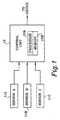
- Figure 1 is a block diagram of the invention. Shown in figure 1 are control unit 10 and sensors 11. Sensors 11 provide at least one equivalent parameter which are communicated to control unit 10. For example, if sensors 11 are air data sensors they each provide several equivalent parameters such as static air pressure, air speed, air temperature, etc.
- the invention is useful for systems having two or more redundant sensors. However, it is particularly useful in systems with three or more redundant sensors as shown in figure 1.
- Control unit 10 includes means for comparing equivalent parameters, dynamically debouncing the raw miscompare data, and implementing the autoreversion logic.
- control unit 10 includes a processor 10A and memory 10B which accomplish these tasks.
- processor 10A and memory 10B which accomplish these tasks.
- Control unit 10 either uses the results itself or communicates the results to other devices which operate on the results.
- control unit 10 itself operates on the sensor data then communicates data or commands to other devices.
- the devices can be virtually any type of actuator, display, controller, or the like.
- Figures 2A and 2B illustrate specific embodiments of the invention.
- Figure 2A shows the invention embodied as part of an EFIS(electronic flight instrument system). Shown in figure 2A are EFIS 20, symbol generator 21, display 22, and sensors 11.
- Sensors 11 may include a variety of sensor types.
- sensors 11 may include air data computers, global positioning sensor systems(GPSS), inertial reference systems(IRS), distance measuring equipment(DME), VOR, and others.
- GPSS global positioning sensor systems
- IRS inertial reference systems
- DME distance measuring equipment
- VOR VOR
- Parameters from sensors 11 are communicated to symbol generator 21.
- Symbol generator 21 performs the functions of control unit 10 above. Symbol generator 21 compares equivalent parameters, dynamically debounces the miscomparisons, and uses predetermined autoreversion logic to decide which of the equivalent parameters to use.
- an electronic display system e.g. EFIS
- the entire sensor which generated the parameter is set invalid and the display system reverts to another sensor.
- This scheme simplifies pilot workload by maintaining consistency on the display. Only one message is required to notify the pilot that a different sensor is now being used. This whole-sensor invalidation approach is supported by the assumption that sensor outputs are closely interrelated. If one output is corrupt there is a high probability that other outputs will also soon be corrupt.
- Symbol generator 21 includes processor 21A and memory 21B. Symbol generator 21 selects the appropriate sensor according to the autoreversion logic and communicates the parameters and pilot notifications to display 22.
- Figure 2B shows the invention embodied as part of an autopilot.
- Figure 2B shows sensors 11, autopilot 23, and actuators 24. Sensors 11 are similar to the sensors in figure 2A. Parameters from sensors 11 are communicated to autopilot 23.
- Autopilot 23 includes processor 23A and memory 23B. Autopilot 23 functions as control unit 10 described above. Autopilot 23 compares equivalent parameters, dynamically debounces the miscomparisons, and selects which parameters to use according to predetermined autoreversion logic. Autopilot 23 uses the parameters in conventional autopilot control algorithms to yield commands which are transmitted to the various actuators associated with the control surfaces of the aircraft.
- Figure 3 is block diagram of the preferred embodiment of a miscompare detector and debounce. Shown in figure 3 are sensor parameters 30, miscompare detector 31 and debounce 32.
- a typical miscompare detector as known in the prior art merely compares two parameters and yields a binary indication of either a compare or miscompare status.
- the invention uses an improved miscompare detector which also yields an indication of the magnitude of the miscomparison.
- Miscompare detector 31 includes filters 33, difference device 34, averaging device 35, absolute value devices 36, gain 37A, bias 37B, summing device 38, and threshold detector 39.
- Equivalent parameters 30 are input into filters.
- Filters 33 are conventional low pass filters to eliminate noise. Filtered parameter signals from both filters 33 are averaged by averaging device to yield an average signal. Similarly, both filtered parameter signals are input to difference device 34 to yield a difference signal indicative of the difference between the two signals.
- difference device 34 The output of difference device 34 is input to absolute value device 36A which communicates the absolute value of the difference between the parameters 30 to threshold detector 39.
- the average of parameters 30 is communicated from average device 35 to absolute value device 36B.
- the absolute value of the average of parameters 30 is communicated from absolute value device 36B to gain 37A.
- the outputs of gain 37A and bias 37B are summed together by summing device 38.
- Gain 37A and bias 37B allow miscompare detector 31 to be adapted for different criteria and parameters as desired for specific applications. For example, an autopilot may have strict criteria while an EFIS may have more relaxed criteria for the same parameter.
- Gain 37A scales the absolute value of the average of parameters 11.
- Bias 37B provides an offset which is summed with output of gain 37A.
- the output of summing device 38 is the threshold and is communicated to threshold detector 39.
- Threshold detector 39 compares the output of absolute value device 36A with the threshold signal from summing device 38.
- the output of detector 39 is a raw parameter miscompare signal indicating if the threshold has been exceeded and the magnitude of the miscompare. This signal is communicated to the dynamic debounce routine 32.
- Dynamic debounce routine 32 uses the raw parameter miscompare signal along with predetermined debounce criteria for the specific parameter to generate a debounced parameter miscompare flag/signal. This flag is used in the autoreversion logic described below.
- Dynamic debounce routine 32 tracks the history of raw parameter miscompares which are used to compute when to set debounced parameter miscompare flags. Debounce routine 32 factors in both the frequency and magnitude of miscomparisons in its computations. For a typical parameter, a several small raw miscomparisons will not cause the debounced miscompare flag to be set. Similarly, a large isolated miscomparison will not cause the miscomparison flag to be set. However, once the frequency and/or magnitude of miscomparisons become sufficiently large, the debounce routine sets the debounced miscompare flag.
- the debounce routine continues to track the history of raw miscomparisons. It is generally undesirable to have the debounce routine frequently toggle a debounced miscompare flag. Also, it is generally not desired to reset a miscompare flag immediately upon the occurrence of raw miscompare signal indicating no miscompare.
- the debounce routine solves these problems by setting criteria which must be satisfied prior to resetting a debounced miscompare flag. A parameter must remain in a compare state for a dynamically determined period of time before the debounced miscompare flag is reset. This dynamic period of time is a function of the history of raw miscompares.
- a history of frequent and/or large raw miscomparisons requires a longer period of no raw miscomparisons before the debounced miscompare flag is reset.
- a history of infrequent and/or small magnitude raw miscomparisons may require a shorter period of no raw miscomparisons before the debounced miscompare flag is reset.
- K 90*16384 20*10 (16384 is 1/2 scale in a 16 bit word)
- gain is zero and the bias is 6 degrees in the preferred embodiment, for use with an EFIS.
- Figure 4 illustrates this idea.
- the dash steps 41 represent a constant magnitude miscompare (x) and the solid steps 42 represent a constant magnitude miscompare (2x) for an given K. It is apparent that the amount of time to reach the 1/2 full scale value for the larger magnitude miscompare is twice as fast as the smaller miscompare.
- the down count(as illustrated in figure 4) is preferably a constant equal to the minimum miscompare thresholds up count. In other words, the down count is as slow as the slowest up count. Therefore, both large and small magnitude miscompares have the same debounce off time if the sum of the counts is saturated at full scale. Similarly, it is possible for a debounced miscompare flag to be set for only one count over the threshold and then the raw miscompare signal to revert to a compare state. In this case, if the magnitude was small, the debounce off time could be equal to only one or two counts only.
- the final step of the invention is the autoreversion process.
- the invention deselects sensors not to be used and automatically reverts to use a different sensor if needed.
- Two variables are typically used in this step.
- the variables are the debounced parameter miscompare flags and the sensor(or parameter) valids.
- the flags and valids are used in conjunction with predetermined reversion logic to make desired reversion decisions.
- Those skilled in the art recognize invention can also be adapted to deselect parameters instead of whole-sensors if desired.
- the preferred embodiment implements the miscompare detector, debounce routine, and autoreversion logic in software. However, other embodiments are possible.
- Figure 5 illustrates predetermined autoreversion logic for two primary flight displays(PFDs) in an aircraft cockpit.
- PFDs primary flight displays
- PFD 1 refers to the sensor initially associated with PFD 1
- PFD 2 refers to the sensor initially associated with PFD 2
- “3rd sensor” refers to the redundant sensor.
- the " ⁇ " represents a miscompare between sensors.
- the method of the invention follows from the above description. Equivalent parameters from at least two sensors are compared, the magnitude of miscomparison between the equivalent parameters is detected, and a signal representative thereof is generated. The signal is dynamically debounced. Finally, sensors are deselected as a function of the debounced parameter miscomparison signal and predetermined autoreversion logic.
- the present invention represents a new and useful method and apparatus for managing redundant sensors.
Landscapes
- Physics & Mathematics (AREA)
- General Physics & Mathematics (AREA)
- Engineering & Computer Science (AREA)
- Automation & Control Theory (AREA)
- Catching Or Destruction (AREA)
- Investigating Or Analyzing Materials By The Use Of Electric Means (AREA)
- Investigating Or Analyzing Materials By The Use Of Fluid Adsorption Or Reactions (AREA)
- Testing Or Calibration Of Command Recording Devices (AREA)
Abstract
Description
Claims (12)
- A multi-sensor validation system in which equivalent parameters from at least two sensors (11A, 11B, 11C) are compared, said system comprising:a control unit (10) in communication with said sensors, said control unit generating at least one debounced miscompare signal as a function of the magnitude and duration of miscomparisons between at least two of said equivalent parameters.
- The multi-sensor validation system according to claim 1 wherein said control unit (10) deselects at least one of said parameters, said deselection being a function of said at least one debounced miscompare signals and predetermined autoreversion logic.
- The multi-sensor validation system according to claim 1 wherein each of said debounced miscompare signals is characterized such that as the magnitude of miscomparison between said equivalent parameters increases the time period for setting the debounced miscompare signal to a miscompare state decreases.
- The multi-sensor validation system according to claim 3 wherein each of said debounced miscompare signals is characterized such that as the magnitude of miscomparison between said at least two equivalent parameters decreases the time period for setting the debounced miscompare signal to a miscompare state increases.
- The multi-sensor validation system according to claim 1 wherein each of said debounced miscompare signals is characterized such that resetting the signal from a miscompare state to a compare state is a function of the magnitude and duration of prior miscomparisons between said equivalent parameters.
- The multi-sensor validation system according to claim 1 wherein said control unit (10) deselects one of said sensors from providing parameter data, said deselection a function of said at least one debounced miscompare signals and predetermined autoreversion logic.
- A multi-sensor validation system in which equivalent parameters from at least two sensors are evaluated, said management system comprising:a) control means for deselecting at least one of said sensors as a provider of data, said control means including,1) compare means for comparing at least two of said equivalent parameters and generating a raw parameter miscompare signal indicative of the magnitude of miscomparison between said equivalent parameters,2) debounce means for generating a debounced parameter miscompare signal as a function of said raw parameter miscompare signal, and,3) autoreversion means for deselecting one of said sensors as a provider of data, said deselecting being a function of said debounced parameter miscompare signal and predetermined autoreversion logic.
- The sensor validation detection system according to claim 7 wherein said debounce means generates said debounced parameter compare signal as a function of the history of said raw parameter miscompare signals for said equivalent parameters.
- The sensor validation detection system according to claim 8 wherein said debounce means generates said debounced miscompare signals as a function of the magnitude and frequency of miscomparison between said equivalent parameters.
- The sensor validation detection system according to claim 9 wherein said debounced parameter miscompare signal is characterized in that as the magnitude of miscomparisons increase, the debounced parameter miscompare signal is set to a miscompare state in a shorter time period and as the magnitude of miscomparisons decreases, the debounced parameter miscompare signal is set to a miscompare state after a longer time period.
- The sensor validation detection system according to claim 10 wherein said debounced parameter miscompare signal is characterized in that as the frequency of miscomparisons increase, the debounced parameter miscompare signal is set to a miscompare state in a shorter time period and as the frequency of miscomparisons decreases, the debounced parameter miscompare signal is set to a miscompare state after a longer time period.
- The sensor validation detection system according to claim 9 wherein said debounced parameter miscompare signal is characterized in that the debounced parameter miscompare signal is reset from a miscompare state to a compare state as a function of the magnitude and frequency of prior raw parameter miscompare signals.
Applications Claiming Priority (2)
| Application Number | Priority Date | Filing Date | Title |
|---|---|---|---|
| US96185097A | 1997-10-31 | 1997-10-31 | |
| US961850 | 1997-10-31 |
Publications (2)
| Publication Number | Publication Date |
|---|---|
| EP0913746A2 true EP0913746A2 (en) | 1999-05-06 |
| EP0913746A3 EP0913746A3 (en) | 2000-04-12 |
Family
ID=25505101
Family Applications (1)
| Application Number | Title | Priority Date | Filing Date |
|---|---|---|---|
| EP98120275A Withdrawn EP0913746A3 (en) | 1997-10-31 | 1998-10-27 | Sensor invalidation system |
Country Status (1)
| Country | Link |
|---|---|
| EP (1) | EP0913746A3 (en) |
Cited By (15)
| Publication number | Priority date | Publication date | Assignee | Title |
|---|---|---|---|---|
| WO2000048883A1 (en) * | 1999-02-18 | 2000-08-24 | Continental Teves Ag & Co. Ohg | Sensor system with monitoring device, notably for an esp system for vehicles |
| WO2000070415A1 (en) * | 1999-05-14 | 2000-11-23 | Honeywell Inc. | Automatic mode detection and rejection of inadvertent mode changes from dual use of sensor input channel |
| FR2842596A1 (en) * | 2002-07-16 | 2004-01-23 | Commissariat Energie Atomique | Automatic sensor testing, compares measurements between sensor in use and reference sensor with replacement if criterion of accuracy is not met |
| FR2855922A1 (en) * | 2003-06-06 | 2004-12-10 | Thales Sa | METHOD AND DEVICE FOR PROCESSING INFORMATION FROM RESPONDENT PRIMARY FLIGHT EQUIPMENT |
| WO2009109655A1 (en) * | 2008-03-07 | 2009-09-11 | Vestas Wind Systems A/S | A control system and a method for controlling a wind turbine |
| WO2009109467A3 (en) * | 2008-03-07 | 2010-09-10 | Vestas Wind Systems A/S | A control system and a method for redundant control of a wind turbine |
| FR2960319A1 (en) * | 2010-05-19 | 2011-11-25 | Airbus Operations Sas | Method for increasing reliability of vibration information provided by sensors on vibrations subjected by aircraft, involves determining or not-determining failure event in processing chain associated to vibration sensor |
| EP2159418A3 (en) * | 2008-08-27 | 2012-01-11 | Nordex Energy GmbH | Method for operating a wind farm with a wind speed measurement device |
| US20140142877A1 (en) * | 2012-11-19 | 2014-05-22 | General Electric Company | Systems and methods for monitoring current values |
| EP2765307A1 (en) * | 2013-02-07 | 2014-08-13 | SSB Wind Systems GmbH & Co. KG | Sensor system and method for monitoring and processing of blade sensor signals in a wind turbine |
| DE10242128B4 (en) * | 2002-09-11 | 2016-09-15 | Robert Bosch Gmbh | Method and device for monitoring a redundant sensor arrangement |
| CN110573857A (en) * | 2018-02-01 | 2019-12-13 | 山东诺方电子科技有限公司 | High and low frequency multi-core sensor system |
| EP4210024A1 (en) * | 2022-01-05 | 2023-07-12 | Honeywell International Inc. | Systems and methods for enabling user control over use of aircraft sensors located onboard an aircraft |
| WO2024125951A1 (en) * | 2022-12-16 | 2024-06-20 | Zf Friedrichshafen Ag | Method for checking the plausibility of a parameter |
| US12091189B2 (en) | 2022-01-05 | 2024-09-17 | Honeywell International Inc. | Systems and methods for enabling user control over use of aircraft sensors located onboard an aircraft |
Family Cites Families (6)
| Publication number | Priority date | Publication date | Assignee | Title |
|---|---|---|---|---|
| US4771427A (en) * | 1986-10-02 | 1988-09-13 | United Technologies Corporation | Equalization in redundant channels |
| US4916612A (en) * | 1987-11-02 | 1990-04-10 | The Boeing Company | Dual channel signal selection and fault detection system |
| DE3928456A1 (en) * | 1989-08-29 | 1991-03-07 | Nord Micro Elektronik Feinmech | METHOD AND CIRCUIT ARRANGEMENT FOR FORMING AN EVALUATION SIGNAL FROM A MULTIPLE NUMBER OF REDUNDANT MEASURING SIGNALS |
| US5550736A (en) * | 1993-04-27 | 1996-08-27 | Honeywell Inc. | Fail-operational fault tolerant flight critical computer architecture and monitoring method |
| EP0720004B1 (en) * | 1994-12-27 | 2000-02-16 | LITEF GmbH | FDIC-method for minimising measurement errors in a measurement arrangement with redundant sensors |
| US5710776A (en) * | 1995-05-15 | 1998-01-20 | The Boeing Company | Signal selection and fault detection apparatus and method |
-
1998
- 1998-10-27 EP EP98120275A patent/EP0913746A3/en not_active Withdrawn
Cited By (22)
| Publication number | Priority date | Publication date | Assignee | Title |
|---|---|---|---|---|
| WO2000048883A1 (en) * | 1999-02-18 | 2000-08-24 | Continental Teves Ag & Co. Ohg | Sensor system with monitoring device, notably for an esp system for vehicles |
| US6625527B1 (en) | 1999-02-18 | 2003-09-23 | Continental Teves Ag & Co. Ohg | Sensor system with monitoring device |
| WO2000070415A1 (en) * | 1999-05-14 | 2000-11-23 | Honeywell Inc. | Automatic mode detection and rejection of inadvertent mode changes from dual use of sensor input channel |
| FR2842596A1 (en) * | 2002-07-16 | 2004-01-23 | Commissariat Energie Atomique | Automatic sensor testing, compares measurements between sensor in use and reference sensor with replacement if criterion of accuracy is not met |
| DE10242128B4 (en) * | 2002-09-11 | 2016-09-15 | Robert Bosch Gmbh | Method and device for monitoring a redundant sensor arrangement |
| WO2004109516A1 (en) * | 2003-06-06 | 2004-12-16 | Thales | Method and device for processing information output by redundant primary flight equipment |
| FR2855922A1 (en) * | 2003-06-06 | 2004-12-10 | Thales Sa | METHOD AND DEVICE FOR PROCESSING INFORMATION FROM RESPONDENT PRIMARY FLIGHT EQUIPMENT |
| WO2009109467A3 (en) * | 2008-03-07 | 2010-09-10 | Vestas Wind Systems A/S | A control system and a method for redundant control of a wind turbine |
| US8546967B2 (en) | 2008-03-07 | 2013-10-01 | Vestas Wind Systems A/S | Control system and a method for controlling a wind turbine |
| US8736092B2 (en) | 2008-03-07 | 2014-05-27 | Vestas Wind Systems A/S | Control system and a method for redundant control of a wind turbine |
| WO2009109655A1 (en) * | 2008-03-07 | 2009-09-11 | Vestas Wind Systems A/S | A control system and a method for controlling a wind turbine |
| EP2159418A3 (en) * | 2008-08-27 | 2012-01-11 | Nordex Energy GmbH | Method for operating a wind farm with a wind speed measurement device |
| US8102067B2 (en) | 2008-08-27 | 2012-01-24 | Nordex Energy Gmbh | Method for the operation of a wind energy plant having a wind velocity measurement device |
| FR2960319A1 (en) * | 2010-05-19 | 2011-11-25 | Airbus Operations Sas | Method for increasing reliability of vibration information provided by sensors on vibrations subjected by aircraft, involves determining or not-determining failure event in processing chain associated to vibration sensor |
| US20140142877A1 (en) * | 2012-11-19 | 2014-05-22 | General Electric Company | Systems and methods for monitoring current values |
| EP2765307A1 (en) * | 2013-02-07 | 2014-08-13 | SSB Wind Systems GmbH & Co. KG | Sensor system and method for monitoring and processing of blade sensor signals in a wind turbine |
| CN110573857A (en) * | 2018-02-01 | 2019-12-13 | 山东诺方电子科技有限公司 | High and low frequency multi-core sensor system |
| CN110651176A (en) * | 2018-02-01 | 2020-01-03 | 山东诺方电子科技有限公司 | Rotation method of multi-core sensor neutron sensor |
| CN110933950A (en) * | 2018-02-01 | 2020-03-27 | 山东诺方电子科技有限公司 | Method for isolating and recovering abnormal sub-sensors in multi-core sensor |
| EP4210024A1 (en) * | 2022-01-05 | 2023-07-12 | Honeywell International Inc. | Systems and methods for enabling user control over use of aircraft sensors located onboard an aircraft |
| US12091189B2 (en) | 2022-01-05 | 2024-09-17 | Honeywell International Inc. | Systems and methods for enabling user control over use of aircraft sensors located onboard an aircraft |
| WO2024125951A1 (en) * | 2022-12-16 | 2024-06-20 | Zf Friedrichshafen Ag | Method for checking the plausibility of a parameter |
Also Published As
| Publication number | Publication date |
|---|---|
| EP0913746A3 (en) | 2000-04-12 |
Similar Documents
| Publication | Publication Date | Title |
|---|---|---|
| EP0913746A2 (en) | Sensor invalidation system | |
| CA1164067A (en) | Sensor fault detection by activity monitoring | |
| US9593962B2 (en) | Systems and methods for attitude fault detection based on integrated GNSS/inertial hybrid filter residuals | |
| Willsky | A survey of design methods for failure detection in dynamic systems | |
| US7107176B2 (en) | Sensor fusion using self evaluating process sensors | |
| US4926364A (en) | Method and apparatus for determining weighted average of process variable | |
| EP3006899B1 (en) | Systems and methods for attitude fault detection based on air data and aircraft control settings | |
| EP0743583B1 (en) | Monitoring systems for detecting failures in fly-by-wire aircraft flight control systems | |
| US10858123B2 (en) | Methods and systems for detecting data anomalies | |
| US20200183424A1 (en) | Flight control system for determining a fault based on error between a measured and an estimated angle of attack | |
| EP3663772B1 (en) | Flight control system for determining estimated dynamic pressure based on lift and drag coefficients | |
| US9701418B2 (en) | Pilot fatigue detection system and method from aircraft control device movement | |
| US6298286B1 (en) | Method of preventing potentially hazardously misleading attitude data | |
| CN108369109B (en) | Method for monitoring at least two redundant sensors | |
| WO1999023628A1 (en) | Method and apparatus of monitoring a navigation system using deviation signals from navigation sensors | |
| EP4089497B1 (en) | Methods and systems for depicting avionics data anomalies | |
| US20200183423A1 (en) | Flight control system for determining a common mode pneumatic fault | |
| GB2135782A (en) | Oscillatory sensor failure monitor | |
| US20210394790A1 (en) | Imu fault monitoring method and apparatus for multiple imus/gnss integrated navigation system | |
| CN111337957B (en) | Autonomous integrity monitoring method and system for satellite-borne navigation receiver | |
| CN117870657A (en) | A monitoring method, device and storage medium based on heterogeneous sensor configuration | |
| US20030020487A1 (en) | Method and system for sensor fault detection | |
| US7933725B2 (en) | Using sensor spectral energy to detect and/or isolate sensor faults | |
| US20060287809A1 (en) | Method and device for processing information output by redundant primary flight equipment | |
| Feng et al. | Hybrid online multi-sensor error detection and functional redundancy for artificial pancreas control systems |
Legal Events
| Date | Code | Title | Description |
|---|---|---|---|
| PUAI | Public reference made under article 153(3) epc to a published international application that has entered the european phase |
Free format text: ORIGINAL CODE: 0009012 |
|
| AK | Designated contracting states |
Kind code of ref document: A2 Designated state(s): DE FR GB IT |
|
| AX | Request for extension of the european patent |
Free format text: AL;LT;LV;MK;RO;SI |
|
| PUAL | Search report despatched |
Free format text: ORIGINAL CODE: 0009013 |
|
| AK | Designated contracting states |
Kind code of ref document: A3 Designated state(s): AT BE CH CY DE DK ES FI FR GB GR IE IT LI LU MC NL PT SE |
|
| AX | Request for extension of the european patent |
Free format text: AL;LT;LV;MK;RO;SI |
|
| 17P | Request for examination filed |
Effective date: 20000426 |
|
| AKX | Designation fees paid |
Free format text: DE FR GB IT |
|
| 17Q | First examination report despatched |
Effective date: 20010831 |
|
| STAA | Information on the status of an ep patent application or granted ep patent |
Free format text: STATUS: THE APPLICATION IS DEEMED TO BE WITHDRAWN |
|
| 18D | Application deemed to be withdrawn |
Effective date: 20020111 |