EP0913265B1 - Image printing apparatus - Google Patents
Image printing apparatus Download PDFInfo
- Publication number
- EP0913265B1 EP0913265B1 EP98304476A EP98304476A EP0913265B1 EP 0913265 B1 EP0913265 B1 EP 0913265B1 EP 98304476 A EP98304476 A EP 98304476A EP 98304476 A EP98304476 A EP 98304476A EP 0913265 B1 EP0913265 B1 EP 0913265B1
- Authority
- EP
- European Patent Office
- Prior art keywords
- printing
- cutting
- image signal
- image
- cutting position
- Prior art date
- Legal status (The legal status is an assumption and is not a legal conclusion. Google has not performed a legal analysis and makes no representation as to the accuracy of the status listed.)
- Expired - Lifetime
Links
Images




Classifications
-
- B—PERFORMING OPERATIONS; TRANSPORTING
- B41—PRINTING; LINING MACHINES; TYPEWRITERS; STAMPS
- B41J—TYPEWRITERS; SELECTIVE PRINTING MECHANISMS, i.e. MECHANISMS PRINTING OTHERWISE THAN FROM A FORME; CORRECTION OF TYPOGRAPHICAL ERRORS
- B41J11/00—Devices or arrangements of selective printing mechanisms, e.g. ink-jet printers or thermal printers, for supporting or handling copy material in sheet or web form
- B41J11/008—Controlling printhead for accurately positioning print image on printing material, e.g. with the intention to control the width of margins
-
- B—PERFORMING OPERATIONS; TRANSPORTING
- B41—PRINTING; LINING MACHINES; TYPEWRITERS; STAMPS
- B41J—TYPEWRITERS; SELECTIVE PRINTING MECHANISMS, i.e. MECHANISMS PRINTING OTHERWISE THAN FROM A FORME; CORRECTION OF TYPOGRAPHICAL ERRORS
- B41J11/00—Devices or arrangements of selective printing mechanisms, e.g. ink-jet printers or thermal printers, for supporting or handling copy material in sheet or web form
- B41J11/0065—Means for printing without leaving a margin on at least one edge of the copy material, e.g. edge-to-edge printing
-
- B—PERFORMING OPERATIONS; TRANSPORTING
- B41—PRINTING; LINING MACHINES; TYPEWRITERS; STAMPS
- B41J—TYPEWRITERS; SELECTIVE PRINTING MECHANISMS, i.e. MECHANISMS PRINTING OTHERWISE THAN FROM A FORME; CORRECTION OF TYPOGRAPHICAL ERRORS
- B41J11/00—Devices or arrangements of selective printing mechanisms, e.g. ink-jet printers or thermal printers, for supporting or handling copy material in sheet or web form
- B41J11/66—Applications of cutting devices
- B41J11/663—Controlling cutting, cutting resulting in special shapes of the cutting line, e.g. controlling cutting positions, e.g. for cutting in the immediate vicinity of a printed image
-
- B—PERFORMING OPERATIONS; TRANSPORTING
- B41—PRINTING; LINING MACHINES; TYPEWRITERS; STAMPS
- B41J—TYPEWRITERS; SELECTIVE PRINTING MECHANISMS, i.e. MECHANISMS PRINTING OTHERWISE THAN FROM A FORME; CORRECTION OF TYPOGRAPHICAL ERRORS
- B41J11/00—Devices or arrangements of selective printing mechanisms, e.g. ink-jet printers or thermal printers, for supporting or handling copy material in sheet or web form
- B41J11/66—Applications of cutting devices
- B41J11/666—Cutting partly, e.g. cutting only the uppermost layer of a multiple-layer printing material
-
- B—PERFORMING OPERATIONS; TRANSPORTING
- B41—PRINTING; LINING MACHINES; TYPEWRITERS; STAMPS
- B41J—TYPEWRITERS; SELECTIVE PRINTING MECHANISMS, i.e. MECHANISMS PRINTING OTHERWISE THAN FROM A FORME; CORRECTION OF TYPOGRAPHICAL ERRORS
- B41J11/00—Devices or arrangements of selective printing mechanisms, e.g. ink-jet printers or thermal printers, for supporting or handling copy material in sheet or web form
- B41J11/66—Applications of cutting devices
- B41J11/70—Applications of cutting devices cutting perpendicular to the direction of paper feed
Definitions
- the present invention relates to an image printing apparatus for, after printing an image on printing paper on the basis of an image signal, cutting the paper to obtain cut printing paper.
- FIG. 16 roughly shows a structure of a printing unit (hereinafter referred to as a printing mechanical unit) 12 of the image printing apparatus using a thermal transfer recording method with a roll type of printing paper.
- a thermal head 1 for patterning an image signal to thermally transfer it to printing paper is in contact with an ink sheet 2 coated by a thermal-soluble or thermal-sublimation ink for thermal transfer recording.
- the ink sheet 2 and the printing paper 3 are brought into intimate contact with the thermal head 1 by being pressed by a platen roller 4 opposed to the thermal head 1, so that an image pattern in the thermal head 1 is thermally transferred to the printing paper 3 via the ink sheet 2.
- the ink sheet 2 and the printing paper 3 are sent out by the rotation of the platen roller 4.
- the ink sheet 2 and the printing paper are long roll types of paper.
- the ink sheet 2 is supplied from an ink sheet supply roll 201, and rolled up by an ink sheet take-up roll 202.
- the printing paper 3 is supplied from a printing paper supply roll 301, sent in a discharge direction via the platen roller 4 by a pinch roller 5, and cut by a cutter 6 on the basis of a cutting command from a CPU 10.
- the image printing apparatus 90 is an apparatus for making a print by receiving an image signal inputted from the outside. It has an input terminal T1 for inputting a digital image signal.
- the input terminal T1 is directly connected to a memory controller 22 which is an input and output interface of an image or control signal.
- the memory controller 22 is connected to a frame memory 21 for storing picture information of one frame, a CPU (central processing unit) 10, and a transfer circuit 23 for making a data conversion for printing.
- the transfer circuit 23 is connected to the thermal head 1 of the printing mechanical unit 12.
- the CPU 10 reads or writes an image signal from and to the frame memory 21 via the memory controller 22, and also has a function for controlling the printing mechanical unit 12 via a mechanical controller 11 which will be described later.
- the CPU 10 is connected to the mechanical controller 11 for controlling the mechanism of the printing mechanical unit 12, and the mechanical controller 11 is connected to all the equipment described with reference to FIG. 16.
- the CPU 10 is also connected to a programmable ROM 13 for storing, for example, a predetermined cutting position of the printing paper.
- the digital image signal inputted via the input terminal T1 is temporarily stored into the frame memory 21 via the memory controller 22 under the control of the CPU 10.
- the image signal stored in the frame memory 21 is read by the transfer circuit 23 via the memory controller 22 under the control of the CPU 10.
- the transfer circuit 23 converts the image signal into data for printing, and send it to the thermal head 1 of the printing mechanical unit 12.
- the data conversion of the image signal into the data for printing by the transfer circuit 23 includes a color conversion from an RGB signal to a YMC (yellow, magenta, and cyanogen) signal, a conversion from a YMC signal to a pulse signal for operating the thermal head, or the like.
- the thermal head 1 heats a heater line (an array of heating elements disposed on the head) for a given time to sink a thermal-soluble or thermal-sublimation ink applied to the ink sheet 2 into the printing paper 3 by means of thermal solution or thermal sublimation, thereby printing an image on the printing paper 3 on the basis of the data for printing obtained from the transfer circuit 23.
- a heater line an array of heating elements disposed on the head
- the printed printing paper is sent out by the pinch roller 5 of the printing mechanical unit 12, and cut by the cutter 6 on the basis of the cutting command from the CPU 10.
- a cutting position of the printed printing paper has been preset and stored in the programmable ROM 13.
- the CPU 10 gives the cutting command which indicates the cutting position stored in the programmable ROM 13 to the cutter 6 of the printing mechanical unit 12 via the mechanical controller 11.
- the programmable ROM 13 needs to be rewritten.
- the printing paper 3 has a blank area of a length L1 from the heater line of the thermal head 1 to the pinch roller 5.
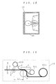
- FIG. 18 shows an example of cut printing paper 30 outputted from the image printing apparatus 90. As shown in the figure, an area of the length L1 from the top end of the cut printing paper 30 to a printing start position RS is blank. This blank area is a margin M1 which is so wide that one can hold it.
- the printing paper is cut only one time after printing to a predetermined size at a cutting position CP in the vicinity of a printing end position RE, so that the wide margin M1 remains on the cut printing paper 30. If the cutting position CP is shifted to the opposite direction to a discharge direction of the paper, a margin M2 corresponding to a shift length L2 of the cutting position CP remains.
- a width W1 of a heater line 16, which is a print width of the thermal head 1 is smaller than a width W2 of the printing paper 3 as shown in FIG. 19, a margin M3 of a length L3 and M4 of a length L4 also remain at the left and right of the printing paper 30, respectively, after printing.
- the margins M1 to M4 remain even after the area is divided into printing images 311.
- the conventional image printing apparatus 90 leaves the margins M1 to M4 at the top and bottom or the left and right of the cut printing paper 30. Especially at the printing start position RS, the wide margin M1 remains.
- EP-A-0 767 066 relates to a printer with cutting means for cutting the recording sheet.
- the lengths of the leading and trailing margins can be input by the user. If not set by the user, the margins are set to zero.
- the recording sheet has position marks which can be sensed and used to determine the cutting position.
- a first aspect of the present invention is directed to an image printing apparatus as claimed in claim 1.
- control means determines the first cutting position that is on the side of the print area not less than the maximum shift length to be caused by the cutting means with respect to the printing start position, and the final cutting position that is on the side of the print area not less than the maximum shift length to be caused by the cutting means with respect to the printing end position.
- the print area includes a multiple print area where a plurality of printing images are longitudinally printed adjacent to each other; and the control means determines a border between adjacent printing images of the plurality of printing images as at least one intermediate cutting position, and gives the cutting command which indicates the at least one intermediate cutting position as well as the first and final cutting positions, to the cutting means.
- the data conversion means includes: image signal processing means for receiving the image signal, and obtaining a processed image signal by processing the image signal so that a picture pattern having a predetermined width is laterally printed at both longitudinal ends of each of the plurality of printing images on the printing paper; and processed image signal conversion means for converting the processed image signal into the data for printing.
- the image signal processing means sets the predetermined width of the picture pattern to be not less than the maximum shift length to be caused by the cutting means.
- the image signal processing means further receives a pattern signal for specifying a predetermined pattern, and obtains the processed image signal by processing the image signal so that the picture pattern including the predetermined pattern is printed.
- the print width by the printing means corresponding to the lateral direction of the printing paper is set to be not less than a predetermined width of the printing paper.
- the control means determines the first cutting position that is on the side of the print area with respect to the printing start position of the print area and the final cutting position that is on the side of the print area with respect to the printing end position of the print area, and gives the cutting command which indicates the first and final cutting positions to the cutting means.
- control means determines the first cutting position that is on the side of the print area not less than the maximum shift length to be caused by the cutting means with respect to the printing start position, and the final cutting position that is on the side of the print area not less than the maximum shift length with respect to the cutting end position.
- control means determines a border between adjacent printing images of the plurality of printing images as at least one intermediate cutting position, and gives the cutting command which indicates at least one intermediate cutting position as well as the first and final cutting positions, to the cutting means.
- the image signal processing means obtains a processed image signal by processing an image signal so that a picture pattern having a predetermined width is laterally printed in both longitudinal ends of each of the plurality of printing images on the printing paper.
- the printing paper will be always cut at the picture pattern having a predetermined width. Namely, one image would never extend over two pieces of cut printing paper. This provides plural pieces of cut printing paper having good appearances.
- the image signal processing means sets the predetermined width of the picture pattern to be not less than the maximum shift length to be made by the cutting means. Thus, even with the maximum shift length, the printing paper will be always cut at the picture pattern having the predetermined width.
- the image signal processing means further receives the pattern signal for specifying a predetermined pattern, and processes the image signal so that the picture pattern including the predetermined pattern is printed.
- an additional value can be added to the original image by providing a pattern signal for specifying a predetermined pattern matching the image to be printed, to the image signal processing means. This improves plural pieces of cut printing paper in appearance.
- the present invention provides the image printing apparatus for producing cut printing paper which is entirely an effective print area without any margin.
- FIG. 1 is a block diagram of a structure of an image printing apparatus using a thermal transfer recording method according to a first preferred embodiment of the present invention.
- a CPU 10A is connected to a cutting position determination device 14 for voluntarily determining a cutting position of printing paper.
- the CPU 10A has a cutting position automatic calculation function for automatically determining the cutting position on the basis of print information stored in a mechanical controller 11 which will be described later, so as not to leave any margin.
- a width W3 of a heater line 17 of a thermal head 1a is larger than a width W2 of the printing paper 3 as shown in FIG. 2, both left and right edges of the heater line 17 jut out beyond the printing paper 3. This allows the printing paper 3 to be printed to the very edges without any left or right margin.
- a discharge direction is assumed as a longitudinal direction of the printing paper 3, and a direction perpendicular to the discharge direction as a lateral direction of the printing paper 3.
- a printing mechanical unit 12 is similar to that of the conventional unit in FIG. 16 except that the thermal head 1 is substituted by the thermal head 1a, so that the following description will be given with reference to FIG. 16.
- a digital image signal inputted via an input terminal T1 is temporarily stored in a frame memory 21 via a memory controller 22 under the control of the CPU 10A.
- the image signal stored in the frame memory 21 is read by a transfer circuit 23 via the memory controller 22 under the control of the CPU 10A.
- the transfer circuit 23 converts the image signal into data for printing to send it to the thermal head 1a of the printing mechanical unit 12.
- the data conversion of the image signal by the transfer circuit 23 includes a color conversion from an RGB signal into a YMC (yellow, magenta, and cyanogen) signal, a conversion from the YMC signal into a pulse signal for operating the thermal head, or the like.
- the thermal head 1a then heats a heater line for a given time to sink a thermal-soluble or thermal-sublimation ink coated on an ink sheet into the printing paper 3 by means of thermal solution or thermal sublimation, thereby printing an image on the printing paper 3 on the basis of the data for printing obtained from the transfer circuit 23.
- the printing paper 3 can be printed to the very edges in its lateral direction without any margin. Namely, the whole printing paper 3 from the printing start position RS to the printing end position RE can be an effective print area. As in the conventional case, however, a margin M1 of a length L1 from the top end R0 of the printing paper to the printing start position RS still remains.
- the printed printing paper 3 is sent out by a pinch roller 5 of the printing mechanical unit 12, and cut by a cutter 6.
- the cutter 6 is controlled by a cutting command from the CPU 10A via the mechanical controller 11.
- the printed printing paper 3 needs to be cut at a first cutting position C1 in the vicinity of the printing start position RS and at a final cutting position C2 in the vicinity of the printing end position RE.
- the CPU 10A outputs the cutting command which indicates the first and final cutting positions C1 and C2 satisfying the following conditions (1) and (2):
- the first cutting position C1 is determined so as to be on the side of the print area (from the printing start position RS to the printing end position RE) with respect to the printing start position RS of the print area, while the final cutting position C2 is determined so as to be on the side of the print area with respect to the printing end position RE of the print area.
- the printing paper 3 is laterally cut by the cutter 6 under the cutting command which indicates the first and final cutting positions C1 and C2 satisfying the conditions (1) and (2).
- the printing paper can be always cut at the print area. This provides cut printing paper 33 without any margin at the top and bottom or left and right as shown in FIG. 4.
- printed printing paper 34 needs to be cut at an intermediate cutting position C2 between two printing images as well as at first and final cutting positions C1 and C3 in the vicinity of the printing start position RS and printing end position RE, respectively.
- the CPU 10A outputs a cutting command which indicates the first and final cutting positions C1 and C3 satisfying the following conditions (11) and (12), and the intermediate cutting position C2 satisfying the following condition (13):
- the first cutting position C1 is determined so as to be on the side of the print area with respect to the printing start position RS of the print area, and the final cutting position C3 so as to be on the side of the print area with respect to the printing end position RE of the print area.
- the printing paper 3 is laterally cut by the cutter 6 on the basis of the cutting command which indicates the first and final cutting positions C1 and C3 satisfying the conditions (11) and (12), and the intermediate cutting position C2 satisfying the condition (13).
- the printing paper can be always cut at the print area. This provides plural pieces of cut printing paper 341 without any margin at the top and bottom or left and right as shown in FIG. 6.
- P pieces of cut printing paper without any margin at the top and bottom or left and right can be obtained by applying the aforementioned conditions (11) to (13) to the final cutting position C(P+1) and the intermediate cutting position CP (from C2 to CP). Further, the multiple printing includes either cases where all printing images are the same or where they are different from each other.
- the length from the printing start position RS to the printing end position RE (corresponding to X in FIG. 3 and X2 in FIG. 5) is fixed.
- the length L1 of the margin M1 can be uniquely determined according to the structure of the printing mechanical unit 12, and the maximum shift lengths ⁇ S1 and ⁇ S2 (or ⁇ S3) of the first and final cutting positions, respectively, can be previously obtained.
- the lengths (N, N2, M or the like) satisfying the conditions (1) and (2) or (11) and (12) and specifying the first and final cutting positions can be preset.
- the first and final cutting positions may be able to set in a programmable ROM 13. It may be also possible to determine a desired cutting position by the cutting position determination device 14 while ignoring the information stored in the programmable ROM 13. For instance, when there is a change in the structure of the printing mechanical unit 12 or in the contents of the print including the size of the print area, the number of printing images, or the like, the determination of the cutting position by the cutting position determination device 14 becomes effective.
- the printing paper can be simply and easily cut under the control of the CPU 10A by determining the cutting position by the cutting position determination device 14. This achieves an easy-to-use image printing apparatus for users.
- the other cutting positions may be determined on the basis of the final cutting position.
- the cutting position to be determined by the cutting position determination device 14 is not limited to the first or final cutting position.
- the device 14 may determine other cutting positions necessary for the multiple printing.
- the CPU 10A has the cutting position automatic calculation function for automatically determining the other cutting positions on the basis of the print information from the mechanical controller 11 as well as the reference cutting position and the number of cuttings from the cutting position determination device 14.
- the other cutting positions can be automatically and appropriately calculated with this function.
- the CPU 10A can automatically calculate all the cutting positions satisfying the aforementioned conditions (1) and (2) or (11) to (13) only with the print information.
- This print information is provided to the mechanical controller 11 before printing, for example, by the input from information input means (not shown).
- FIG. 7 is a flow chart of the cutting operation of the image printing apparatus according to the first preferred embodiment.
- a final cutting position CK and the number of cuttings K obtained from the cutting position determination device 14 are recognized at a step S1.
- step S2 whether the printing is multiple or single is determined on the basis of whether the number of cuttings K is not less than 3 or not at a step S2.
- the process goes to a step S3, while for the multiple printing, to a step S4.
- the first cutting position C1 satisfying the aforementioned conditions (11) and (12), and the intermediate cutting positions C2 to C(K-1) satisfying the aforementioned condition (13), are obtained.
- step S3 or S4 the cutting positions C1 through CK corresponding to the number of printing images are determined. Then, the information of all the cutting positions C1 through CK is transferred to the mechanical controller 11 at a step S5, and, by controlling the operation of the cutter 6 at a step S6, the printing paper is laterally cut per printing image unit. In this way, (K-1) pieces of cut printing paper without any margin at the top and bottom or left and right are obtained.
- the shift of the intermediate cutting position C2 causes one of the images to extend over two pieces of cut printing paper, thereby deteriorating a part of the cut printing paper in appearance.
- FIG. 12 is a block diagram of a structure of an image printing apparatus according to a second preferred embodiment of the present invention, featuring a newly provided image signal processing part 18.
- the image signal processing part 18 receives an image signal of an original image such as an image 42 in FIG. 13, from an input terminal T1, and also a pattern signal for specifying a frame picture pattern such as a frame picture pattern 41 in FIG. 14 from a pattern input terminal T2.
- a programmable ROM 13 previously stored is the size of the frame picture pattern which is preferably not less than the maximum shift length of the intermediate cutting position.
- the image signal processing part 18 outputs a processed image signal of the image 43 as shown in FIG. 15 to the memory controller 22.
- the processed image signal is obtained by adding the frame picture pattern 15 having patterns specified by the pattern signal and the frame size obtained from the programmable ROM 13, to the original image.
- the other components or operations are all similar to those of the first preferred embodiment.
- the frame picture pattern 15 Since the processed image signal containing the frame picture pattern is provided by the image signal processing part 18 to the memory controller 22 according to the second preferred embodiment, the frame picture pattern 15 will be always printed at both top and bottom parts (longitudinal ends) of each printing image in multiple printing. Namely, the frame picture pattern 15 is always printed at an intermediate cutting position between images and its vicinity. Thus, even if the intermediate cutting position is somewhat shifted in the longitudinal direction, the printing paper is always cut at the frame picture pattern 15. Consequently, plural pieces of cut photographic pictures would not be deteriorated in appearance.
- the printing paper can be always cut at the frame picture pattern 15.
- plural pieces of cut printing paper would not be deteriorated in appearance.
- an additional value can be added to an original image by providing the pattern signal for specifying the pattern matching the image to be printed to the pattern input terminal T2. This improves plural pieces of cut printing paper in appearance.
- the image signal processing part 18 inputs the pattern signal of the frame picture pattern, instead of the pattern signal, an image signal for specifying the frame picture pattern itself may be directly inputted and composed with the image signal obtained from the input terminal T1. In this case, the programmable ROM 13 does not need to store the size of the frame picture pattern.
- the image signal processing part 18 of the second preferred embodiment inputs the image signal via the input terminal T1 and the pattern signal via the input terminal T2 as shown in FIG. 12, those signals may be inputted via only one input terminal by multiplexing or time-sharing the image signal and the pattern signal.
Landscapes
- Handling Of Sheets (AREA)
- Controlling Rewinding, Feeding, Winding, Or Abnormalities Of Webs (AREA)
Description
- The present invention relates to an image printing apparatus for, after printing an image on printing paper on the basis of an image signal, cutting the paper to obtain cut printing paper.
- FIG. 16 roughly shows a structure of a printing unit (hereinafter referred to as a printing mechanical unit) 12 of the image printing apparatus using a thermal transfer recording method with a roll type of printing paper.
- In FIG. 16, a
thermal head 1 for patterning an image signal to thermally transfer it to printing paper is in contact with anink sheet 2 coated by a thermal-soluble or thermal-sublimation ink for thermal transfer recording. Under theink sheet 2 provided isprinting paper 3. Theink sheet 2 and theprinting paper 3 are brought into intimate contact with thethermal head 1 by being pressed by aplaten roller 4 opposed to thethermal head 1, so that an image pattern in thethermal head 1 is thermally transferred to theprinting paper 3 via theink sheet 2. After the thermal transfer, theink sheet 2 and theprinting paper 3 are sent out by the rotation of theplaten roller 4. - The
ink sheet 2 and the printing paper are long roll types of paper. Theink sheet 2 is supplied from an inksheet supply roll 201, and rolled up by an ink sheet take-up roll 202. Theprinting paper 3 is supplied from a printingpaper supply roll 301, sent in a discharge direction via theplaten roller 4 by apinch roller 5, and cut by acutter 6 on the basis of a cutting command from aCPU 10. - Next, a structure of an
image printing apparatus 90 will be described with reference to FIG. 17. Theimage printing apparatus 90 is an apparatus for making a print by receiving an image signal inputted from the outside. It has an input terminal T1 for inputting a digital image signal. - The input terminal T1 is directly connected to a
memory controller 22 which is an input and output interface of an image or control signal. - The
memory controller 22 is connected to aframe memory 21 for storing picture information of one frame, a CPU (central processing unit) 10, and atransfer circuit 23 for making a data conversion for printing. Thetransfer circuit 23 is connected to thethermal head 1 of the printingmechanical unit 12. - The
CPU 10 reads or writes an image signal from and to theframe memory 21 via thememory controller 22, and also has a function for controlling the printingmechanical unit 12 via amechanical controller 11 which will be described later. - Further, the
CPU 10 is connected to themechanical controller 11 for controlling the mechanism of the printingmechanical unit 12, and themechanical controller 11 is connected to all the equipment described with reference to FIG. 16. TheCPU 10 is also connected to aprogrammable ROM 13 for storing, for example, a predetermined cutting position of the printing paper. - In such a structure, the digital image signal inputted via the input terminal T1 is temporarily stored into the
frame memory 21 via thememory controller 22 under the control of theCPU 10. - The image signal stored in the
frame memory 21 is read by thetransfer circuit 23 via thememory controller 22 under the control of theCPU 10. Thetransfer circuit 23 converts the image signal into data for printing, and send it to thethermal head 1 of the printingmechanical unit 12. The data conversion of the image signal into the data for printing by thetransfer circuit 23 includes a color conversion from an RGB signal to a YMC (yellow, magenta, and cyanogen) signal, a conversion from a YMC signal to a pulse signal for operating the thermal head, or the like. - Then, the
thermal head 1 heats a heater line (an array of heating elements disposed on the head) for a given time to sink a thermal-soluble or thermal-sublimation ink applied to theink sheet 2 into theprinting paper 3 by means of thermal solution or thermal sublimation, thereby printing an image on theprinting paper 3 on the basis of the data for printing obtained from thetransfer circuit 23. - The printed printing paper is sent out by the
pinch roller 5 of the printingmechanical unit 12, and cut by thecutter 6 on the basis of the cutting command from theCPU 10. A cutting position of the printed printing paper has been preset and stored in theprogrammable ROM 13. Thus, theCPU 10 gives the cutting command which indicates the cutting position stored in theprogrammable ROM 13 to thecutter 6 of the printingmechanical unit 12 via themechanical controller 11. In order to change the cutting position, theprogrammable ROM 13 needs to be rewritten. - According to the structure of the printing
mechanical unit 12 as shown in FIG. 16, theprinting paper 3 has a blank area of a length L1 from the heater line of thethermal head 1 to thepinch roller 5. FIG. 18 shows an example of cutprinting paper 30 outputted from theimage printing apparatus 90. As shown in the figure, an area of the length L1 from the top end of thecut printing paper 30 to a printing start position RS is blank. This blank area is a margin M1 which is so wide that one can hold it. - In the conventional
image printing apparatus 90, the printing paper is cut only one time after printing to a predetermined size at a cutting position CP in the vicinity of a printing end position RE, so that the wide margin M1 remains on thecut printing paper 30. If the cutting position CP is shifted to the opposite direction to a discharge direction of the paper, a margin M2 corresponding to a shift length L2 of the cutting position CP remains. - Since a width W1 of a
heater line 16, which is a print width of thethermal head 1, is smaller than a width W2 of theprinting paper 3 as shown in FIG. 19, a margin M3 of a length L3 and M4 of a length L4 also remain at the left and right of theprinting paper 30, respectively, after printing. - Likewise, even for a multiple printing where a plurality of printing images are longitudinally printed in one print area as is the case with
cut printing paper 31 in FIG. 20, the margins M1 to M4 remain even after the area is divided intoprinting images 311. - As described above, the conventional
image printing apparatus 90 leaves the margins M1 to M4 at the top and bottom or the left and right of thecut printing paper 30. Especially at the printing start position RS, the wide margin M1 remains. - EP-A-0 767 066 relates to a printer with cutting means for cutting the recording sheet. The lengths of the leading and trailing margins can be input by the user. If not set by the user, the margins are set to zero. The recording sheet has position marks which can be sensed and used to determine the cutting position.
- A first aspect of the present invention is directed to an image printing apparatus as claimed in
claim 1. - Preferably, in the image printing apparatus according to a second aspect of the present invention, the control means determines the first cutting position that is on the side of the print area not less than the maximum shift length to be caused by the cutting means with respect to the printing start position, and the final cutting position that is on the side of the print area not less than the maximum shift length to be caused by the cutting means with respect to the printing end position.
- Preferably, in the image printing apparatus according to a third aspect of the present invention, the print area includes a multiple print area where a plurality of printing images are longitudinally printed adjacent to each other; and the control means determines a border between adjacent printing images of the plurality of printing images as at least one intermediate cutting position, and gives the cutting command which indicates the at least one intermediate cutting position as well as the first and final cutting positions, to the cutting means.
- Preferably, in the image printing apparatus according to a fourth aspect of the present invention, the data conversion means includes: image signal processing means for receiving the image signal, and obtaining a processed image signal by processing the image signal so that a picture pattern having a predetermined width is laterally printed at both longitudinal ends of each of the plurality of printing images on the printing paper; and processed image signal conversion means for converting the processed image signal into the data for printing.
- Preferably, in the image printing apparatus according to a fifth aspect of the present invention, the image signal processing means sets the predetermined width of the picture pattern to be not less than the maximum shift length to be caused by the cutting means.
- Preferably, in the image printing apparatus according to a sixth aspect of the present invention, the image signal processing means further receives a pattern signal for specifying a predetermined pattern, and obtains the processed image signal by processing the image signal so that the picture pattern including the predetermined pattern is printed.
- In the image printing apparatus according to the first aspect, the print width by the printing means corresponding to the lateral direction of the printing paper, is set to be not less than a predetermined width of the printing paper. Further, the control means determines the first cutting position that is on the side of the print area with respect to the printing start position of the print area and the final cutting position that is on the side of the print area with respect to the printing end position of the print area, and gives the cutting command which indicates the first and final cutting positions to the cutting means. Thus, even if the first and final cutting positions are somewhat shifted in the longitudinal direction of the printing paper in cutting, the cut printing paper which is entirely an effective print area without any margin, is obtainable.
- Further, in the image printing apparatus according to the second aspect, the control means determines the first cutting position that is on the side of the print area not less than the maximum shift length to be caused by the cutting means with respect to the printing start position, and the final cutting position that is on the side of the print area not less than the maximum shift length with respect to the cutting end position. Thus, even with the maximum shift length in the opposite direction to the print area, the printing paper will be always cut at the print area. Consequently, the cut printing paper which is entirely an effective print area without any margin, is obtainable.
- Further, in the image printing apparatus according to the third aspect, the control means determines a border between adjacent printing images of the plurality of printing images as at least one intermediate cutting position, and gives the cutting command which indicates at least one intermediate cutting position as well as the first and final cutting positions, to the cutting means. Thus, plural pieces of cut printing paper which are entirely effective print areas without any margin, are obtainable.
- In the image printing apparatus according to the fourth aspect, the image signal processing means obtains a processed image signal by processing an image signal so that a picture pattern having a predetermined width is laterally printed in both longitudinal ends of each of the plurality of printing images on the printing paper. Thus, even if at least one intermediate cutting position is somewhat shifted in the longitudinal direction of the printing paper in cutting, the printing paper will be always cut at the picture pattern having a predetermined width. Namely, one image would never extend over two pieces of cut printing paper. This provides plural pieces of cut printing paper having good appearances.
- Further, in the image printing apparatus according to the fifth aspect, the image signal processing means sets the predetermined width of the picture pattern to be not less than the maximum shift length to be made by the cutting means. Thus, even with the maximum shift length, the printing paper will be always cut at the picture pattern having the predetermined width.
- This certainly prevents one image from extending over two pieces of cut printing paper, thereby providing plural pieces of cut printing paper having good appearances.
- In the image printing apparatus according to the sixth aspect, the image signal processing means further receives the pattern signal for specifying a predetermined pattern, and processes the image signal so that the picture pattern including the predetermined pattern is printed. Thus, an additional value can be added to the original image by providing a pattern signal for specifying a predetermined pattern matching the image to be printed, to the image signal processing means. This improves plural pieces of cut printing paper in appearance.
- The present invention provides the image printing apparatus for producing cut printing paper which is entirely an effective print area without any margin.
- These and other objects, features, aspects and advantages of the present invention will become more apparent from the following detailed description of the present invention when taken in conjunction with the accompanying drawings.
-
- FIG. 1 is a block diagram of an image printing apparatus according to a first preferred embodiment of the present invention.
- FIG. 2 is a perspective view of a heater line of a thermal head.
- FIG. 3 is an illustration of printed printing paper before cutting for a single printing.
- FIG. 4 is an illustration of the printed printing paper after cutting for the single printing.
- FIG. 5 is an illustration of printed printing paper before cutting for a multiple printing.
- FIG. 6 is an illustration of the printed printing paper after cutting for the multiple printing.
- FIG. 7 is a flow chart of a cutting operation of the image printing apparatus according to the first preferred embodiment.
- FIG. 8 is an illustration of printed printing paper before cutting for the multiple printing.
- FIG. 9 is an illustration of the printed printing paper after cutting for the multiple printing.
- FIG. 10 is an illustration of printed printing paper before cutting for the multiple printing according to a second preferred embodiment of the present invention.
- FIG. 11 is an illustration of the printed printing paper after cutting for the multiple printing according to the second preferred embodiment.
- FIG. 12 is a block diagram of an image printing apparatus according to a third preferred embodiment of the present invention.
- FIG. 13 is an illustration of an original image.
- FIG. 14 is an illustration of a frame picture pattern.
- FIG. 15 is an illustration of an image overlaid on the frame picture pattern.
- FIG. 16 is an illustration of a mechanical unit of the image printing apparatus.
- FIG. 17 is a block diagram of a structure of a conventional image printing apparatus.
- FIG. 18 is an illustration of printed printing paper after cutting for the single printing, produced by the conventional image printing apparatus.
- FIG. 19 is a perspective view of a heater line of a conventional thermal head.
- FIG. 20 is an illustration of printed printing paper after cutting for the multiple printing, produced by the conventional image printing apparatus.
-
- FIG. 1 is a block diagram of a structure of an image printing apparatus using a thermal transfer recording method according to a first preferred embodiment of the present invention. As shown in the figure, a
CPU 10A is connected to a cuttingposition determination device 14 for voluntarily determining a cutting position of printing paper. Also, theCPU 10A has a cutting position automatic calculation function for automatically determining the cutting position on the basis of print information stored in amechanical controller 11 which will be described later, so as not to leave any margin. - Further, since a width W3 of a
heater line 17 of a thermal head 1a is larger than a width W2 of theprinting paper 3 as shown in FIG. 2, both left and right edges of theheater line 17 jut out beyond theprinting paper 3. This allows theprinting paper 3 to be printed to the very edges without any left or right margin. For convenience of description, a discharge direction is assumed as a longitudinal direction of theprinting paper 3, and a direction perpendicular to the discharge direction as a lateral direction of theprinting paper 3. - As similar to those of the conventional
image printing apparatus 90 in FIG. 17, the other components are indicated by the same reference numerals, and omitted from the description. Further, the structure of a printingmechanical unit 12 is similar to that of the conventional unit in FIG. 16 except that thethermal head 1 is substituted by the thermal head 1a, so that the following description will be given with reference to FIG. 16. - In such a structure, a digital image signal inputted via an input terminal T1 is temporarily stored in a
frame memory 21 via amemory controller 22 under the control of theCPU 10A. - The image signal stored in the
frame memory 21 is read by atransfer circuit 23 via thememory controller 22 under the control of theCPU 10A. Thetransfer circuit 23 converts the image signal into data for printing to send it to the thermal head 1a of the printingmechanical unit 12. The data conversion of the image signal by thetransfer circuit 23 includes a color conversion from an RGB signal into a YMC (yellow, magenta, and cyanogen) signal, a conversion from the YMC signal into a pulse signal for operating the thermal head, or the like. - The thermal head 1a then heats a heater line for a given time to sink a thermal-soluble or thermal-sublimation ink coated on an ink sheet into the
printing paper 3 by means of thermal solution or thermal sublimation, thereby printing an image on theprinting paper 3 on the basis of the data for printing obtained from thetransfer circuit 23. - At this time, by expanding a print width of the thermal head 1a (i.e. the width W3 of the heater line 17) larger than the width W2 of the
printing paper 3, theprinting paper 3 can be printed to the very edges in its lateral direction without any margin. Namely, thewhole printing paper 3 from the printing start position RS to the printing end position RE can be an effective print area. As in the conventional case, however, a margin M1 of a length L1 from the top end R0 of the printing paper to the printing start position RS still remains. - The printed
printing paper 3 is sent out by apinch roller 5 of the printingmechanical unit 12, and cut by acutter 6. Thecutter 6 is controlled by a cutting command from theCPU 10A via themechanical controller 11. - For a single printing where one printing image is printed on the printed
printing paper 3 as shown in FIG. 3, the printedprinting paper 3 needs to be cut at a first cutting position C1 in the vicinity of the printing start position RS and at a final cutting position C2 in the vicinity of the printing end position RE. At this time, theCPU 10A outputs the cutting command which indicates the first and final cutting positions C1 and C2 satisfying the following conditions (1) and (2): - (1) A distance M from the top end R0 of the printing paper to the first
cutting position C1 satisfies {M≧L1 +Δ S1}, where Δ S1 is the maximum shift
length of the cutting position C1 to be made by the
cutter 6 in cutting. - (2) A distance N from the first cutting position C1 to the final cutting
position C2 satisfies {M+N+Δ S2≦L1+X}, where Δ S2 is the maximum shift
length of the final cutting position C2 to be made by the
cutter 6 in cutting (= Δ S1), and X is the length from the printing start position RS to the printing end position RE. -
- With consideration of the shift to be made by the
cutter 6 in cutting, the first cutting position C1 is determined so as to be on the side of the print area (from the printing start position RS to the printing end position RE) with respect to the printing start position RS of the print area, while the final cutting position C2 is determined so as to be on the side of the print area with respect to the printing end position RE of the print area. - In this manner, the
printing paper 3 is laterally cut by thecutter 6 under the cutting command which indicates the first and final cutting positions C1 and C2 satisfying the conditions (1) and (2). - Therefore, even if the first and final cutting positions C1 and C2 are shifted to the maximum shift length Δ S1 and Δ S2 in the opposite direction to the print area, respectively, the printing paper can be always cut at the print area. This provides cut
printing paper 33 without any margin at the top and bottom or left and right as shown in FIG. 4. - For a multiple printing where a plurality of printing images (two in FIG. 5) are longitudinally printed adjacent to each other in one print area as shown in FIG. 5, printed
printing paper 34 needs to be cut at an intermediate cutting position C2 between two printing images as well as at first and final cutting positions C1 and C3 in the vicinity of the printing start position RS and printing end position RE, respectively. In this case, theCPU 10A outputs a cutting command which indicates the first and final cutting positions C1 and C3 satisfying the following conditions (11) and (12), and the intermediate cutting position C2 satisfying the following condition (13): - (11) A distance M from the top end R0 of the printing paper to the first
cutting position C1 satisfies {M≧L1 +Δ S1}, where Δ S1 is the maximum shift
length of the first cutting position C1 to be made by the
cutter 6 in cutting; - (12) A distance N2 from the first cutting position C1 to the final cutting
position C3 satisfies {M+N2+Δ S3≦L1+X2}, where Δ S3 is the maximum shift
length of the final cutting position C3 to be made by the
cutter 6 in cutting (= Δ S1), and X2 is the length from the printing start position RS to the printing end position RE; - (13) The intermediate cutting position C2 is determined so as to be in the vicinity of a border between adjacent two printing images.
-
- With consideration of the shift to be made by the
cutter 6 in cutting, the first cutting position C1 is determined so as to be on the side of the print area with respect to the printing start position RS of the print area, and the final cutting position C3 so as to be on the side of the print area with respect to the printing end position RE of the print area. - In this manner, the
printing paper 3 is laterally cut by thecutter 6 on the basis of the cutting command which indicates the first and final cutting positions C1 and C3 satisfying the conditions (11) and (12), and the intermediate cutting position C2 satisfying the condition (13). - Therefore, even if the first cutting position C1 and the final cutting position C3 are shifted to the maximum shift length Δ S1 and Δ S2 in the opposite direction to the print area, the printing paper can be always cut at the print area. This provides plural pieces of
cut printing paper 341 without any margin at the top and bottom or left and right as shown in FIG. 6. - Even for the multiple printing where P (≧ 3) printing images are continuously printed, P pieces of cut printing paper without any margin at the top and bottom or left and right can be obtained by applying the aforementioned conditions (11) to (13) to the final cutting position C(P+1) and the intermediate cutting position CP (from C2 to CP). Further, the multiple printing includes either cases where all printing images are the same or where they are different from each other.
- When the number of printing images and the sizes of the print area or printing paper are all fixed, the length from the printing start position RS to the printing end position RE (corresponding to X in FIG. 3 and X2 in FIG. 5) is fixed. In this case, the length L1 of the margin M1 can be uniquely determined according to the structure of the printing
mechanical unit 12, and the maximum shift lengths ΔS1 and ΔS2 (or ΔS3) of the first and final cutting positions, respectively, can be previously obtained. Thus, the lengths (N, N2, M or the like) satisfying the conditions (1) and (2) or (11) and (12) and specifying the first and final cutting positions, can be preset. - When the contents of the print has been already known as described above, the first and final cutting positions may be able to set in a
programmable ROM 13. It may be also possible to determine a desired cutting position by the cuttingposition determination device 14 while ignoring the information stored in theprogrammable ROM 13. For instance, when there is a change in the structure of the printingmechanical unit 12 or in the contents of the print including the size of the print area, the number of printing images, or the like, the determination of the cutting position by the cuttingposition determination device 14 becomes effective. - Especially, when the cutting operation is simply repeated at fixed positions as in the step for obtaining the
cut printing paper 33 in FIG. 4 or 341 in FIG. 6, the printing paper can be simply and easily cut under the control of theCPU 10A by determining the cutting position by the cuttingposition determination device 14. This achieves an easy-to-use image printing apparatus for users. - Further, it may be also possible to set some cutting positions in the
programmable ROM 13 and determine the remaining cutting positions by the cuttingposition determination device 14. For example, as in the conventional case, with only the final cutting position set in theprogrammable ROM 13, the other cutting positions may be determined on the basis of the final cutting position. - The cutting position to be determined by the cutting
position determination device 14 is not limited to the first or final cutting position. Thedevice 14 may determine other cutting positions necessary for the multiple printing. - Further, it may be also possible to determine only a reference cutting position (generally the final cutting position) and the number of cuttings by the cutting
position determination device 14, and obtain the other cutting positions by theCPU 10A. TheCPU 10A has the cutting position automatic calculation function for automatically determining the other cutting positions on the basis of the print information from themechanical controller 11 as well as the reference cutting position and the number of cuttings from the cuttingposition determination device 14. Thus, for the multiple printing, for example, the other cutting positions can be automatically and appropriately calculated with this function. - Further, if the print information of the
mechanical controller 11 includes not only the type of printing, multiple or single, but also the type of the printing paper or the number of printing images in the multiple printing, theCPU 10A can automatically calculate all the cutting positions satisfying the aforementioned conditions (1) and (2) or (11) to (13) only with the print information. This print information is provided to themechanical controller 11 before printing, for example, by the input from information input means (not shown). - FIG. 7 is a flow chart of the cutting operation of the image printing apparatus according to the first preferred embodiment. Although there are many methods for determining the cutting positions with the aforementioned conditions (1) and (2) or (11) to (13), we will now describe, as an example, one cutting operation performed under the control of the
CPU 10A which receives the final cutting position and the number of cuttings from the cuttingposition determination device 14. - First, a final cutting position CK and the number of cuttings K obtained from the cutting
position determination device 14 are recognized at a step S1. - Then, whether the printing is multiple or single is determined on the basis of whether the number of cuttings K is not less than 3 or not at a step S2. For the single printing, the process goes to a step S3, while for the multiple printing, to a step S4.
- At the step S3, with reference to the final cutting position C2, the first cutting position C1 satisfying the aforementioned conditions (1) and (2) is obtained.
- At the step S4, with reference to the final cutting position CK, the first cutting position C1 satisfying the aforementioned conditions (11) and (12), and the intermediate cutting positions C2 to C(K-1) satisfying the aforementioned condition (13), are obtained.
- Through either of the step S3 or S4, the cutting positions C1 through CK corresponding to the number of printing images are determined. Then, the information of all the cutting positions C1 through CK is transferred to the
mechanical controller 11 at a step S5, and, by controlling the operation of thecutter 6 at a step S6, the printing paper is laterally cut per printing image unit. In this way, (K-1) pieces of cut printing paper without any margin at the top and bottom or left and right are obtained. - When picture patterns on both top and bottom ends of the printing image are plain as shown in FIG. 5, even if the intermediate cutting position C2 is somewhat shifted in the longitudinal direction, the
cut printing paper 341 would not be deteriorated in appearance as shown in FIG. 6. - However, when a pattern in the vicinity of a border between two printing images is not plain, the shift of the intermediate cutting position C2 causes one of the images to extend over two pieces of cut printing paper, thereby deteriorating a part of the cut printing paper in appearance.
- For example, when the upper part of a person's body is printed at a border between two printing images, and the intermediate cutting position C2 therebetween is shifted in the discharge direction as shown in FIG. 8, a part of the image to be generally on cut printing paper 351_1 is left on cut printing paper 351_2 as shown in FIG. 9. This deteriorates the cut printing paper 351_2 in appearance.
- To avoid this problem, considering the shift length of the intermediate cutting position C2, a
frame picture pattern 15 is printed with the original image as shown in FIG. 10. Thus, even with the shift length of the intermediate cutting position C2, the two pieces of cut printing paper 361_1 and 361_2 would not be deteriorated in appearance as shown in FIG. 11. This is the characteristics of the image printing apparatus according to the second preferred embodiment. - FIG. 12 is a block diagram of a structure of an image printing apparatus according to a second preferred embodiment of the present invention, featuring a newly provided image
signal processing part 18. - The image
signal processing part 18 receives an image signal of an original image such as animage 42 in FIG. 13, from an input terminal T1, and also a pattern signal for specifying a frame picture pattern such as aframe picture pattern 41 in FIG. 14 from a pattern input terminal T2. In aprogrammable ROM 13 previously stored is the size of the frame picture pattern which is preferably not less than the maximum shift length of the intermediate cutting position. - The image
signal processing part 18 outputs a processed image signal of theimage 43 as shown in FIG. 15 to thememory controller 22. The processed image signal is obtained by adding theframe picture pattern 15 having patterns specified by the pattern signal and the frame size obtained from theprogrammable ROM 13, to the original image. The other components or operations are all similar to those of the first preferred embodiment. - Since the processed image signal containing the frame picture pattern is provided by the image
signal processing part 18 to thememory controller 22 according to the second preferred embodiment, theframe picture pattern 15 will be always printed at both top and bottom parts (longitudinal ends) of each printing image in multiple printing. Namely, theframe picture pattern 15 is always printed at an intermediate cutting position between images and its vicinity. Thus, even if the intermediate cutting position is somewhat shifted in the longitudinal direction, the printing paper is always cut at theframe picture pattern 15. Consequently, plural pieces of cut photographic pictures would not be deteriorated in appearance. - At this time, if the size of the frame picture pattern is set to be not less than the maximum shift length of the intermediate cutting position, even with the maximum shift length, the printing paper can be always cut at the
frame picture pattern 15. Thus, plural pieces of cut printing paper would not be deteriorated in appearance. - Further, an additional value can be added to an original image by providing the pattern signal for specifying the pattern matching the image to be printed to the pattern input terminal T2. This improves plural pieces of cut printing paper in appearance.
- Although the image
signal processing part 18 inputs the pattern signal of the frame picture pattern, instead of the pattern signal, an image signal for specifying the frame picture pattern itself may be directly inputted and composed with the image signal obtained from the input terminal T1. In this case, theprogrammable ROM 13 does not need to store the size of the frame picture pattern. - Further, although the image
signal processing part 18 of the second preferred embodiment inputs the image signal via the input terminal T1 and the pattern signal via the input terminal T2 as shown in FIG. 12, those signals may be inputted via only one input terminal by multiplexing or time-sharing the image signal and the pattern signal. - While the invention has been described in detail, the foregoing description is in all aspects illustrative and not restrictive. It is understood that numerous other modifications and variations can be devised without departing from the scope of the invention.
Claims (6)
- An image printing apparatus comprising:characterised in that said control means <10A, 11, 13, 14> determines a first cutting position that is within said print area and a final cutting position that is within said print area, and gives said cutting command which indicates said first and final cutting positions to said cutting means <4 to 6>.data conversion means <18, 21 to 23> for receiving an image signal from the outside and converting said image signal into data for printing;printing means <1a, 2, 4, 5, 201, 202> for printing at least one printing image longitudinally on said printing paper to obtain a print area, on the basis of said data for printing;control means <10A, 11, 13, 14> for giving a cutting command which indicates a cutting position of said printing paper; andcutting means <4 to 6> for laterally cutting said printing paper on the basis of said cutting command;
- The image printing apparatus according to Claim 1, wherein
said control means <10A, 11, 13, 14> determines that the first cutting position is at a distance from the printing start position that is not less than the maximum shift of the cutting position in the longitudinal direction caused by said cutting means, and said final cutting position is at a distance from the printing and position that is not less than the maximum shift of the cutting position in the longitudinal direction caused by said cutting means <4 to 6>. - The image printing apparatus according to Claim 1 or Claim 2, wherein
said print area includes a multiple print area where a plurality of printing images are longitudinally printed adjacent to each other; and
said control means <10A, 11, 13, 14> determines a border between adjacent printing images of said plurality of images as at least one intermediate cutting position, and gives said cutting command which indicates said at least one intermediate cutting position as well as said first and final cutting positions, to said cutting means <4 to 6>. - The image printing apparatus according to Claim 3, wherein
said data conversion means includes:image signal processing means <13, 18> for receiving said image signal, and obtaining a processed image signal by processing said image signal so that a picture pattern having a predetermined width is laterally printed at both longitudinal ends of each of said plurality of printing images on said printing paper; andprocessed image signal conversion means <21 to 23> for converting said processed image signal into said data for printing. - The image printing apparatus according to Claim 4, wherein
said image signal processing means <13, 18> sets said predetermined width of said picture pattern to be not less than the maximum shift of the cutting position in the longitudinal direction caused by said cutting means <4 to 6>. - The image printing apparatus according to Claim 4, wherein
said image signal processing means <13, 18> further receives a pattern signal for specifying a predetermined pattern, and obtains said processed image signal by processing said image signal so that said picture pattern including said predetermined pattern is printed.
Applications Claiming Priority (3)
| Application Number | Priority Date | Filing Date | Title |
|---|---|---|---|
| JP29831997 | 1997-10-30 | ||
| JP298319/97 | 1997-10-30 | ||
| JP29831997A JP3756302B2 (en) | 1997-10-30 | 1997-10-30 | Image printing device |
Publications (3)
| Publication Number | Publication Date |
|---|---|
| EP0913265A2 EP0913265A2 (en) | 1999-05-06 |
| EP0913265A3 EP0913265A3 (en) | 1999-06-30 |
| EP0913265B1 true EP0913265B1 (en) | 2002-10-02 |
Family
ID=17858117
Family Applications (1)
| Application Number | Title | Priority Date | Filing Date |
|---|---|---|---|
| EP98304476A Expired - Lifetime EP0913265B1 (en) | 1997-10-30 | 1998-06-05 | Image printing apparatus |
Country Status (7)
| Country | Link |
|---|---|
| US (1) | US6281981B1 (en) |
| EP (1) | EP0913265B1 (en) |
| JP (1) | JP3756302B2 (en) |
| KR (1) | KR100295207B1 (en) |
| CN (1) | CN1142862C (en) |
| DE (1) | DE69808404T2 (en) |
| TW (1) | TW439662U (en) |
Families Citing this family (15)
| Publication number | Priority date | Publication date | Assignee | Title |
|---|---|---|---|---|
| JP2001310849A (en) * | 2000-04-28 | 2001-11-06 | Konica Corp | Image recording device |
| US7095526B1 (en) | 2000-10-18 | 2006-08-22 | Eastman Kodak Company | Automatic layout method for full-bleed printing |
| JP3919683B2 (en) | 2003-03-10 | 2007-05-30 | キヤノン株式会社 | Development device |
| CN100448681C (en) * | 2003-07-10 | 2009-01-07 | 精工电子有限公司 | Forward conveying and cutting method of heat-sensitive adhesive paper and its printing machine |
| FR2875170B1 (en) | 2004-09-13 | 2006-11-24 | Sagem | PRINTING METHOD USING A THERMAL PRINTER |
| US7930958B2 (en) | 2005-07-14 | 2011-04-26 | Provo Craft And Novelty, Inc. | Blade housing for electronic cutting apparatus |
| JP4962310B2 (en) * | 2007-12-27 | 2012-06-27 | セイコーエプソン株式会社 | RECORDING CONTROL DEVICE, RECORDING CONTROL METHOD, AND PROGRAM |
| JP5188186B2 (en) * | 2008-01-10 | 2013-04-24 | キヤノン株式会社 | Cartridge and printer device |
| WO2011028593A2 (en) | 2009-08-26 | 2011-03-10 | Provo Craft And Novelty, Inc. | Crafting apparatus including a workpiece feed path bypass assembly and workpiece feed path analyzer |
| US20110280999A1 (en) | 2009-12-23 | 2011-11-17 | Provo Craft And Novelty, Inc. | Foodstuff Crafting Apparatus, Components, Assembly, and Method for Utilizing the Same |
| JP5753415B2 (en) * | 2011-03-22 | 2015-07-22 | セイコーエプソン株式会社 | Printing apparatus and printing apparatus control method |
| JP5314070B2 (en) * | 2011-03-28 | 2013-10-16 | シャープ株式会社 | Printing system |
| JP6447559B2 (en) * | 2016-03-28 | 2019-01-09 | ブラザー工業株式会社 | Printing apparatus, printing method, and printing program |
| JP6834765B2 (en) | 2017-05-16 | 2021-02-24 | 株式会社リコー | Inkjet printer and 3D printing method |
| JP7380184B2 (en) * | 2019-12-23 | 2023-11-15 | ブラザー工業株式会社 | printing device |
Family Cites Families (13)
| Publication number | Priority date | Publication date | Assignee | Title |
|---|---|---|---|---|
| US4888717A (en) * | 1984-11-02 | 1989-12-19 | Adolph Coors Company | Web lateral position control apparatus and method |
| EP0475625B1 (en) * | 1990-08-31 | 1996-05-22 | New Oji Paper Co., Ltd. | Printer having a sheet cutter |
| JP2643569B2 (en) * | 1990-09-12 | 1997-08-20 | ブラザー工業株式会社 | Tape printer |
| JPH05293794A (en) | 1992-04-16 | 1993-11-09 | Ricoh Co Ltd | Image forming device |
| JPH068549A (en) | 1992-06-25 | 1994-01-18 | Sony Corp | Video printer |
| JPH06320826A (en) * | 1993-03-15 | 1994-11-22 | Brother Ind Ltd | Tape printer |
| JPH0781163A (en) * | 1993-09-14 | 1995-03-28 | Toshiba Corp | Thermal recording device |
| KR0132870B1 (en) * | 1993-09-29 | 1998-04-15 | 김광호 | Apparatus and method for printing |
| JP2910537B2 (en) | 1993-12-09 | 1999-06-23 | 日産自動車株式会社 | Auxiliary air control device for internal combustion engine |
| JP3403855B2 (en) | 1995-04-07 | 2003-05-06 | 三菱電機株式会社 | Image printer device |
| JP3533779B2 (en) * | 1995-10-04 | 2004-05-31 | カシオ計算機株式会社 | Color printing equipment |
| JPH09267525A (en) * | 1996-04-03 | 1997-10-14 | Nec Corp | Data communicating apparatus |
| JP3555350B2 (en) * | 1996-08-26 | 2004-08-18 | ノーリツ鋼機株式会社 | Photo processing equipment |
-
1997
- 1997-10-30 JP JP29831997A patent/JP3756302B2/en not_active Expired - Fee Related
-
1998
- 1998-06-01 TW TW089215330U patent/TW439662U/en not_active IP Right Cessation
- 1998-06-05 DE DE69808404T patent/DE69808404T2/en not_active Expired - Fee Related
- 1998-06-05 EP EP98304476A patent/EP0913265B1/en not_active Expired - Lifetime
- 1998-06-25 US US09/104,421 patent/US6281981B1/en not_active Expired - Fee Related
- 1998-06-29 CN CNB981152996A patent/CN1142862C/en not_active Expired - Fee Related
- 1998-08-07 KR KR1019980032121A patent/KR100295207B1/en not_active Expired - Fee Related
Also Published As
| Publication number | Publication date |
|---|---|
| KR19990036587A (en) | 1999-05-25 |
| CN1142862C (en) | 2004-03-24 |
| US6281981B1 (en) | 2001-08-28 |
| EP0913265A2 (en) | 1999-05-06 |
| DE69808404D1 (en) | 2002-11-07 |
| CN1216271A (en) | 1999-05-12 |
| EP0913265A3 (en) | 1999-06-30 |
| KR100295207B1 (en) | 2001-07-12 |
| JPH11129562A (en) | 1999-05-18 |
| JP3756302B2 (en) | 2006-03-15 |
| DE69808404T2 (en) | 2003-06-18 |
| HK1019575A1 (en) | 2000-02-18 |
| TW439662U (en) | 2001-06-07 |
Similar Documents
| Publication | Publication Date | Title |
|---|---|---|
| US6281981B1 (en) | Image printing apparatus | |
| EP1315363B1 (en) | Print control method | |
| CN101668640B (en) | Thermal printer and control method thereof | |
| WO2008008188A2 (en) | Producing standard format and wide-format prints | |
| JPH1044482A (en) | Thermal transfer recording method | |
| US5450213A (en) | Facsimile machine capable of printing plurality of original images in main scanning direction of recording paper | |
| HK1019575B (en) | Image printing apparatus | |
| US7084891B2 (en) | Photoprinter printing image on recording paper | |
| KR20020062179A (en) | Printing control apparatus and method, and heat transfer printing medium | |
| US5262799A (en) | Recording apparatus with auxiliary recording and method for same | |
| US6398433B1 (en) | Printing method for block copy film and block copy printer | |
| US5623299A (en) | Thermal transfer recording apparatus with ink sheet and recording medium transported by predetermined amounts | |
| JP3403855B2 (en) | Image printer device | |
| JP3301392B2 (en) | Video printer | |
| US5777654A (en) | Printing method and apparatus in which a print sheet is pressed to a drum by an ink film | |
| JP2002254687A (en) | Thermal printer control device, control method, and control program | |
| JPH10309817A (en) | Thermal transfer printer and ink sheet | |
| JP2002326414A (en) | Color printing equipment | |
| JPH066928Y2 (en) | Thermal fax machine | |
| JPH06237352A (en) | Facsimile equipment | |
| JP2000015887A (en) | Thermal printer | |
| JPH11334120A (en) | Sublimation type thermal transfer video printer | |
| JPH04125165A (en) | color thermal printer | |
| JPS6311362A (en) | Method for measuring density characteristic in gradation printer | |
| JP2002187328A (en) | Printer, control method thereof, and computer-readable information recording medium |
Legal Events
| Date | Code | Title | Description |
|---|---|---|---|
| PUAI | Public reference made under article 153(3) epc to a published international application that has entered the european phase |
Free format text: ORIGINAL CODE: 0009012 |
|
| AK | Designated contracting states |
Kind code of ref document: A2 Designated state(s): DE FR GB NL |
|
| AX | Request for extension of the european patent |
Free format text: AL;LT;LV;MK;RO;SI |
|
| PUAL | Search report despatched |
Free format text: ORIGINAL CODE: 0009013 |
|
| AK | Designated contracting states |
Kind code of ref document: A3 Designated state(s): AT BE CH CY DE DK ES FI FR GB GR IE IT LI LU MC NL PT SE |
|
| AX | Request for extension of the european patent |
Free format text: AL;LT;LV;MK;RO;SI |
|
| 17P | Request for examination filed |
Effective date: 19990623 |
|
| AKX | Designation fees paid |
Free format text: DE FR GB NL |
|
| 17Q | First examination report despatched |
Effective date: 20000331 |
|
| GRAG | Despatch of communication of intention to grant |
Free format text: ORIGINAL CODE: EPIDOS AGRA |
|
| GRAG | Despatch of communication of intention to grant |
Free format text: ORIGINAL CODE: EPIDOS AGRA |
|
| GRAH | Despatch of communication of intention to grant a patent |
Free format text: ORIGINAL CODE: EPIDOS IGRA |
|
| GRAH | Despatch of communication of intention to grant a patent |
Free format text: ORIGINAL CODE: EPIDOS IGRA |
|
| GRAA | (expected) grant |
Free format text: ORIGINAL CODE: 0009210 |
|
| AK | Designated contracting states |
Kind code of ref document: B1 Designated state(s): DE FR GB NL |
|
| REG | Reference to a national code |
Ref country code: GB Ref legal event code: FG4D |
|
| REF | Corresponds to: |
Ref document number: 69808404 Country of ref document: DE Date of ref document: 20021107 |
|
| ET | Fr: translation filed | ||
| PLBE | No opposition filed within time limit |
Free format text: ORIGINAL CODE: 0009261 |
|
| STAA | Information on the status of an ep patent application or granted ep patent |
Free format text: STATUS: NO OPPOSITION FILED WITHIN TIME LIMIT |
|
| 26N | No opposition filed |
Effective date: 20030703 |
|
| PGFP | Annual fee paid to national office [announced via postgrant information from national office to epo] |
Ref country code: GB Payment date: 20060531 Year of fee payment: 9 |
|
| PGFP | Annual fee paid to national office [announced via postgrant information from national office to epo] |
Ref country code: DE Payment date: 20060601 Year of fee payment: 9 |
|
| PGFP | Annual fee paid to national office [announced via postgrant information from national office to epo] |
Ref country code: FR Payment date: 20060608 Year of fee payment: 9 |
|
| PGFP | Annual fee paid to national office [announced via postgrant information from national office to epo] |
Ref country code: NL Payment date: 20060615 Year of fee payment: 9 |
|
| GBPC | Gb: european patent ceased through non-payment of renewal fee |
Effective date: 20070605 |
|
| NLV4 | Nl: lapsed or anulled due to non-payment of the annual fee |
Effective date: 20080101 |
|
| REG | Reference to a national code |
Ref country code: FR Ref legal event code: ST Effective date: 20080229 |
|
| PG25 | Lapsed in a contracting state [announced via postgrant information from national office to epo] |
Ref country code: NL Free format text: LAPSE BECAUSE OF NON-PAYMENT OF DUE FEES Effective date: 20080101 Ref country code: DE Free format text: LAPSE BECAUSE OF NON-PAYMENT OF DUE FEES Effective date: 20080101 |
|
| PG25 | Lapsed in a contracting state [announced via postgrant information from national office to epo] |
Ref country code: GB Free format text: LAPSE BECAUSE OF NON-PAYMENT OF DUE FEES Effective date: 20070605 |
|
| PG25 | Lapsed in a contracting state [announced via postgrant information from national office to epo] |
Ref country code: FR Free format text: LAPSE BECAUSE OF NON-PAYMENT OF DUE FEES Effective date: 20070702 |