EP0912856B1 - An improved connection arrangement - Google Patents
An improved connection arrangement Download PDFInfo
- Publication number
- EP0912856B1 EP0912856B1 EP97931579A EP97931579A EP0912856B1 EP 0912856 B1 EP0912856 B1 EP 0912856B1 EP 97931579 A EP97931579 A EP 97931579A EP 97931579 A EP97931579 A EP 97931579A EP 0912856 B1 EP0912856 B1 EP 0912856B1
- Authority
- EP
- European Patent Office
- Prior art keywords
- male
- locking
- female
- components
- connector
- Prior art date
- Legal status (The legal status is an assumption and is not a legal conclusion. Google has not performed a legal analysis and makes no representation as to the accuracy of the status listed.)
- Expired - Lifetime
Links
Images



Classifications
-
- F—MECHANICAL ENGINEERING; LIGHTING; HEATING; WEAPONS; BLASTING
- F16—ENGINEERING ELEMENTS AND UNITS; GENERAL MEASURES FOR PRODUCING AND MAINTAINING EFFECTIVE FUNCTIONING OF MACHINES OR INSTALLATIONS; THERMAL INSULATION IN GENERAL
- F16L—PIPES; JOINTS OR FITTINGS FOR PIPES; SUPPORTS FOR PIPES, CABLES OR PROTECTIVE TUBING; MEANS FOR THERMAL INSULATION IN GENERAL
- F16L37/00—Couplings of the quick-acting type
- F16L37/08—Couplings of the quick-acting type in which the connection between abutting or axially overlapping ends is maintained by locking members
- F16L37/084—Couplings of the quick-acting type in which the connection between abutting or axially overlapping ends is maintained by locking members combined with automatic locking
-
- Y—GENERAL TAGGING OF NEW TECHNOLOGICAL DEVELOPMENTS; GENERAL TAGGING OF CROSS-SECTIONAL TECHNOLOGIES SPANNING OVER SEVERAL SECTIONS OF THE IPC; TECHNICAL SUBJECTS COVERED BY FORMER USPC CROSS-REFERENCE ART COLLECTIONS [XRACs] AND DIGESTS
- Y10—TECHNICAL SUBJECTS COVERED BY FORMER USPC
- Y10S—TECHNICAL SUBJECTS COVERED BY FORMER USPC CROSS-REFERENCE ART COLLECTIONS [XRACs] AND DIGESTS
- Y10S285/00—Pipe joints or couplings
- Y10S285/921—Snap-fit
Definitions
- the present invention relates to a connector for coupling objects together, and in particular relates to a connector for the coupling of a male and a female components.
- connectors for the coupling of male and female components by means of a snap fit action.
- Such connectors comprise one or more connecting elements such as lugs or projections on one component which engage upon or with the other component.
- Such connectors sometimes rely upon deformation of the connecting elements during the coupling process, or alternatively upon the radial movement of the connecting elements during the coupling process.
- the connectors may also be prone to being inadvertently uncoupled.
- US-A-4 429 938 discloses an electrical connector with two components which can be assembled by pushing them together in an axial direction.
- a first component (a plug) has an outer cover and an internal part bearing elongate and axially disposed pins which are electrical contacts.
- the second component (a socket) has parts adapted to receive the pins slidingly when the two components are assembled.
- the outer cover has formations which during assembly enter mating L-shaped recesses arranged peripherally on the second component. When the formations have moved as far as possible axially in the recesses, the cover is rotated so that each formation enters a locking position in the bottom arm of its respective "L", so that withdrawal of the first component from the second then requires both a reverse rotation and axial movement of the outer cover.
- the formations are urged into their locking positions by resilient members on the outer cover which, during coupling, bear on angled sections of the second component. Because the pins must enter the second component axially, and the shape of the recesses requires rotation of the outer cover during coupling, the outer cover is given a degree of freedom to rotate with respect to the internal part.
- the connector relies on contact of the resilient members with mating surfaces of the second component to urge the formations on the outer cover into their locking positions. There is no resilient connection between the rotatable locking means (outer cover and its formations) and any such locating means.
- FR-A-2 658 899 discloses a simpler connection arrangement, of the bayonet type. A male and a female component are connected by being pushed axially into engagement with each other.
- US-A-4 887 849 discloses a connection arrangement suitable for automotive use in connecting radiator hoses to radiators, and for similar applications.
- a male component has axially extending flexible fingers which, when the male component is axially pushed into engagement with the female component, deflect outwards after which lugs on the ends of the fingers snap inwardly behind shoulders formed in the female component.
- the male and female components are formed in such a way that they can move relative to each other only in an axial direction during coupling.
- the locking means in this connector namely the fingers with their lugs, bend about axes perpendicular to the axis of the connector.
- This connector differs from the others discussed above in that the male and female components are constrained to move axially only during coupling and uncoupling with no final rotation being required to complete the coupling process. However, a rotation of the whole male component about the connector axis is required to initiate decoupling.
- a connector for coupling a male and a female component according to claim 1.
- the biasing means could include at least one spring.
- the skirt could have one or more guide recesses therein to provide torsional flexibility.
- the skirt could be adapted, when in the locking position, to prevent radial disengagement of the first locking lug(s) from the second locking lug(s).
- each first locking lug could have a face inclined to said axial direction and which slides on a face of the corresponding second locking lug during coupling of said components giving rise to said first rotation of said locking means.
- the connector could be such that in a locked condition of said connector, said locking means is rotatable by a user to a position in which said male and female components are free to move axially apart.
- Said first component could be said male component, said connector further including a seal for sealing between the male and female components in the zone of the coupling.
- the connector could be such that in a locked condition of said connector, the or each abutting pair of first and second locking lugs abut each other at a plane of contact inclined to said axial direction at such an angle that when said first and second components are pulled apart with a predetermined axial force, the first locking lug slides relatively to the second locking lug at said plane of contact until said locking means is rotated about said axial direction sufficiently to cease to lock said male and female components together axially.
- Said locating means could comprise guide projections on one of said male and female components defining guide recesses therebetween and guide projections on the other of said male and female components, wherein, during coupling and uncoupling of said components, said guide projections on said other of the components move through said guide recesses.
- a male member 10 includes a cylindrical outer wall 12, the surface of which is provided with locating/guiding means in the form of a series of male guide projections 16 which are spaced around the outer circumference of the outer wall 12 so as to define gaps or male guide recesses 19 therebetween.
- the male guide projections 16 are located proximate the outer end 18 of the male member 10.
- male member 10 and female member 20 depicted in Fig. 1 are hollow, it should be noted that the male member 10 may also be solid.
- the corresponding female member 20 includes a cylindrical skirt (inner wall) 22, which is provided with locating/guide means in the form of female guide projections 28 which are located away from the open end or mouth 26 of the female member 20.
- the female guide projections 28 extend in an axial direction down the cylindrical skirt (inner wall) 22 of the female member 20.
- a series of female guide projections 28 are located around the cylindrical skirt (inner wall) 22 of the female member 20.
- the series of projections 28 defines a series of female guide recesses 21.
- the male and female members are connected along a longitudinal axis 11.
- the female guide projections 28 on the inner surface of the female member 20 pass neatly through the gaps or male guide recesses 19 defined by the male guide projections 16a, 16b etc., on the outer wall 12 of the male member 10.
- the arrangement does not permit any substantial movement other than axial of the male and female components when the components are at least partially engaged.
- the said grooves or guides can be arranged to allow only one possible dual alignment of the male and female components.
- male locking lugs 14 are provided on the outer surface of the male member 10 and female locking lugs 24 are provided on the inner surface of the female member 20.
- One or more of locking lugs 24 are provided on the inside surface of the skirt of the female member 20 at a location proximate the mouth 26 of the female member 20. 5
- one or more locking lugs 14 are provided on the outside surface of the male member 10 at a location which will result in the respective locking lugs 14 and 24 cooperating to restrain the female member 20 on the male member 10 when the female member 20 is fully fitted.
- a locking member 30 may be employed in applications where there is a need to ensure positive locking between the male and female members, or where a degree of tamper proofing of the connection is desired.
- the locking member 30 takes the form of an annular sleeve or collar which is engaged on the female member 20 by means of a lug 36 which is located in a corresponding outer female guide recess 21 in the wall 22 of the female member 20.
- the locking member 30 may be engaged with the male member 10.
- a tab 34 is provided to enable the user to easily manipulate the locking member between its locked and unlocked positions.
- the locking member 30 includes one or more fingers 32 which are adapted to be located between the male and female members and to restrict the turning movement of the female member 20 relative to the male member 10 and thereby prevent decoupling of the members.
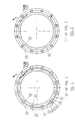
- the positioning of a finger 32 when in the locked position is illustrated in Fig. 2.
- FIG. 3 an alternative configuration of the guide means and locking means is depicted.
- the female guide projections 28 on the female member 20 are located proximate the mouth 26 of the female member 20 and the locking lugs 24 are located away from the mouth 26.
- the locking lugs 14 of the male member 10 are located proximate its end 18 whilst the male guide projections 16 are located away from the end 18.
- the locking lugs 14 of the male member pass over the locking lugs 24 of the female member 20.
- This connector may be employed in applications such as the permanent coupling of pipes and the like.
- a suitable seal may be incorporated into the coupling to provide for sealing between the male and female members in the zone of the coupling.
- the female guide projection 28 on the inside surface of the female member 20 is brought into alignment with the gap 23 between the two male guide projection 16a, 16b on the outer surface 12 of the male member 10.
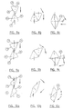
- the locking lug 24 on the female member 20 and the locking lug 14 on the male member 10 are in proximity to each other. In this position the locking lugs 14 and 24 are not in direct axial alignment but are slightly offset as illustrated in Fig. 8a.
- the rotational movement of the skirt of the female member 20 arises from a degree of elastic rotational deflection in the skirt of the female member 20.
- the skirt 22 of the female member 20 may be provided with one or more guide recesses, such as axially extending female guide recesses 21, in order to provide sufficient torsional flexibility in the skirt.
- the skirt of the female member 20 may be of sufficient torsional rigidity so that during the coupling process there is no rotational movement of the portion of the female member 20 carrying the locking lugs 24.
- the rotational movement is provided by torsional flexure in the male member 10 such that the portion of the male member 10 carrying the locking lugs 14 undergoes rotational movement during coupling.
- both the male and female members may be provided with a degree torsional flexure such that the portions of both the male and female members which carry the locking lugs 14 and 24 respectively undergo rotational movement during the coupling process.
- Figs. 7a, 7b, and 7c illustrate the operation of another alternative embodiment of the connection mechanism, wherein rather than relying upon flexure in the skirt of the female member 20, a mechanical biasing arrangement is employed.
- the portion the female member 20 which carries the locking lug 24 is separate from that portion of the female member 20 which carries the female guide projection 28 and can rotate with respect thereto.
- a biasing means such as one or more springs, act between the two portions of the female member 20.
- an alternative embodiment of this form of the invention is to provide the locking lugs of the male member 10 on a biased, rotatable portion such as a ring.
- a further possible alternative is to provide both the male and female members with biased rotatable rings upon which the respective cooperative locking lugs are provided.
- Figs. 8a to 8c, 9a to 9c, and 10a to 10c it is possible to vary the degree of force required to in order to couple the male and female members and to also vary the degree of locking provided by the mechanism once the male and female members have been coupled.
- the outer surfaces 15, 25 of the locking lugs 14 and 24 have a plane of contact which is at an angle relative to the direction of relative movement of the male and female members.
- the degree of force required to couple the members can be varied. This may also be varied by varying the sizing of the lugs and also by varying the axial offset of the lugs.
- the angle between the plane of contact 40 of the locking lugs and the axial plane of the male and female members influences the amount of force required to uncouple the members.
- the angle ⁇ represents the angle between the plane of contact of the locking lugs and a plane orthogonal to the axial plane of the male and female members.
- the force required to uncouple the members is less.
- the present invention can be used in numerous applications. For example, it may be utilised as a coupling mechanism for conduits such as hoses, pipes and the like, or for connecting cables, including electrical cables. It may also be used as a closure arrangement for containers and the like.
Landscapes
- Engineering & Computer Science (AREA)
- General Engineering & Computer Science (AREA)
- Mechanical Engineering (AREA)
- Quick-Acting Or Multi-Walled Pipe Joints (AREA)
- Connections Effected By Soldering, Adhesion, Or Permanent Deformation (AREA)
- Mechanical Coupling Of Light Guides (AREA)
- Coupling Device And Connection With Printed Circuit (AREA)
- Closures For Containers (AREA)
- Details Of Connecting Devices For Male And Female Coupling (AREA)
- Medicines Containing Antibodies Or Antigens For Use As Internal Diagnostic Agents (AREA)
- Radiation-Therapy Devices (AREA)
Abstract
Description
Claims (9)
- A connector for coupling a male (10) and a female (20) component, said connector including:a male and a female component,locating means (16, 19; 28, 21) for locating the male and the female components with respect to each other whereby relative movement of the male and female components is permitted only in an axial direction when said components are at least partially engaged; andlocking means (24) included in a first one of said male and female components for locking the said components to each other and adapted to rotate with respect to said locating means (16, 19; 28, 21) about an axis parallel to said axial direction during coupling and uncoupling of said components, wherein:during said axial relative movement of said components into engagement with each other, said locking means (24) undergoes a first such rotation so that one or more first locking lugs (24) included in said locking means pass one or more corresponding second locking lugs (14) included in the second one of said components, said locking means thereafter undergoing a second such rotation to snap back to a locking position in which said first and second locking lugs are located relative to each other to lock said male and female components together axially; characterised in thatsaid locking means (24) is secured to a further part of said first component by a torsionally flexible skirt (22) or biasing means, said skirt or biasing means being adapted to effect said second rotation after completion of said first rotation.
- A connector according to claim 1, wherein said locking means (24) is secured to said further part by such biasing means, the biasing means including at least one spring.
- A connector according to claim 1, wherein said locking means (24) is secured to said further part by such a skirt (22), the skirt having one or more guide recesses (21 ) therein to provide torsional flexibility.
- A connector according to claim 3, wherein the skirt (22) is adapted, when in the locking position, to prevent radial disengagement of the first locking lug(s) (24) from the second locking lug(s) (14).
- A connector according to any preceding claim, wherein the or each first locking lug (24) has a face (25) inclined to said axial direction and which slides on a face (15) of the corresponding second locking lug (14) during coupling of said components giving rise to said first rotation of said locking means.
- A connector according to any preceding claim, wherein in a locked condition of said connector, said locking means (24) is rotatable by a user to a position in which said male (10) and female (20) components are free to move axially apart.
- A connector according to any preceding claim, wherein said first component is said male component (10) and said connector further includes a seal for sealing between the male (10) and female (20) components in the zone of the coupling.
- A connector according to any preceding claim, wherein in a locked condition of said connector, the or each abutting pair of first (24) and second (14) locking lugs abut each other at a plane of contact inclined to said axial direction at such an angle that when said first and second components are pulled apart with a predetermined axial force, the first locking lug slides relatively to the second locking lug at said plane of contact until said locking means (24) is rotated about said axial direction sufficiently to cease to lock said male (10) and female (20) components together axially.
- A connector according to any preceding claim, wherein said locating means (16, 19; 28, 21) comprises guide projections (16) on one (10) of said male and female components defining guide recesses (19) therebetween and guide projections (28) on the other (20) of said male and female components and wherein, during coupling and uncoupling of said components, said guide projections on said other of the components move through said guide recesses.
Applications Claiming Priority (4)
| Application Number | Priority Date | Filing Date | Title |
|---|---|---|---|
| AUPO1206/96 | 1996-07-24 | ||
| AUPO120696 | 1996-07-24 | ||
| AUPO1206A AUPO120696A0 (en) | 1996-07-24 | 1996-07-24 | Improvements in closure arrangements for containers |
| PCT/AU1997/000468 WO1998004865A1 (en) | 1996-07-24 | 1997-07-24 | An improved connection arrangement |
Publications (3)
| Publication Number | Publication Date |
|---|---|
| EP0912856A1 EP0912856A1 (en) | 1999-05-06 |
| EP0912856A4 EP0912856A4 (en) | 1999-12-01 |
| EP0912856B1 true EP0912856B1 (en) | 2003-10-15 |
Family
ID=3795521
Family Applications (1)
| Application Number | Title | Priority Date | Filing Date |
|---|---|---|---|
| EP97931579A Expired - Lifetime EP0912856B1 (en) | 1996-07-24 | 1997-07-24 | An improved connection arrangement |
Country Status (7)
| Country | Link |
|---|---|
| US (1) | US6244632B1 (en) |
| EP (1) | EP0912856B1 (en) |
| JP (1) | JP3922309B2 (en) |
| AT (1) | ATE252210T1 (en) |
| AU (1) | AUPO120696A0 (en) |
| DE (1) | DE69725581T2 (en) |
| WO (1) | WO1998004865A1 (en) |
Families Citing this family (12)
| Publication number | Priority date | Publication date | Assignee | Title |
|---|---|---|---|---|
| DE19930023C2 (en) * | 1999-06-30 | 2001-05-31 | Wolfgang Vahlbrauk | Pipe connection in the form of a push-in joint |
| JP3621016B2 (en) * | 2000-03-22 | 2005-02-16 | 株式会社水道技術開発機構 | Expansion joints for fluid transportation |
| DE202006004407U1 (en) * | 2006-03-17 | 2007-07-19 | Mann+Hummel Gmbh | Connection for a tubular air guide element on a turbocharger |
| ATE548541T1 (en) * | 2009-12-16 | 2012-03-15 | Borgwarner Inc | EXHAUST TURBOCHARGER |
| US9364651B2 (en) | 2010-02-23 | 2016-06-14 | Smiths Medical Asd, Inc. | Adapter with special fitting |
| US9220833B2 (en) | 2011-06-27 | 2015-12-29 | Smiths Medical Asd, Inc. | Medicament infusion systems |
| US8870238B2 (en) | 2011-06-27 | 2014-10-28 | Smiths Medical Asd, Inc. | Fitting for medicament infusion systems |
| US10737087B2 (en) | 2012-04-17 | 2020-08-11 | Smiths Medical Asd, Inc. | Filling fitting |
| ES2647630T3 (en) * | 2012-12-13 | 2017-12-22 | Guala Closures S.P.A. | Union system of two tubular members and liquid container equipped with said union system |
| US11047175B2 (en) * | 2017-09-29 | 2021-06-29 | Weatherford Technology Holdings, Llc | Combined multi-coupler with rotating locking method for top drive |
| WO2023121869A1 (en) * | 2021-12-20 | 2023-06-29 | Kinetic Pressure Control, Ltd. | Tubular coupling systems and methods |
| CN114770791A (en) * | 2022-03-25 | 2022-07-22 | 千达精密模具(苏州)有限公司 | Raw material mixing device for processing injection molding of electronic equipment |
Citations (1)
| Publication number | Priority date | Publication date | Assignee | Title |
|---|---|---|---|---|
| US4429938A (en) * | 1982-01-06 | 1984-02-07 | Midland-Ross Corporation | Locking device for interfitting members |
Family Cites Families (15)
| Publication number | Priority date | Publication date | Assignee | Title |
|---|---|---|---|---|
| US744788A (en) * | 1903-02-02 | 1903-11-24 | Willie Noble | Hose-pipe coupling. |
| US939436A (en) * | 1909-02-06 | 1909-11-09 | Vincen P Mcvoy | Hose-coupling. |
| US1031587A (en) * | 1911-09-12 | 1912-07-02 | Peder M Reisik | Hose-coupling. |
| US1054812A (en) * | 1912-06-19 | 1913-03-04 | Augustus C Zierath | Drill-pipe with lock-joint. |
| US3588149A (en) * | 1969-08-13 | 1971-06-28 | Amp Inc | Vacuum or pressure coupling devices |
| AU3655071A (en) * | 1970-12-07 | 1973-06-14 | Hogan B A | Liquid valve connection |
| AU4245672A (en) * | 1971-05-27 | 1973-11-22 | Visscher P De | Junction in an ambient fluid |
| GB1501386A (en) * | 1974-02-06 | 1978-02-15 | Bunker Ramo | Plugs for lockable push-pull electrical connectors |
| DE3442327C1 (en) * | 1984-11-20 | 1986-07-10 | Guido Oberdorfer Wap-Maschinen, 7919 Bellenberg | Connecting piece for high-pressure hoses |
| DE3702246C1 (en) | 1987-01-27 | 1988-03-10 | Rasmussen Gmbh | Plug-in coupling for connecting a hose to a pipe |
| FR2626660B1 (en) * | 1988-02-02 | 1990-07-06 | Hutchinson Sa | ASSEMBLY DEVICE FOR A HEAT EXCHANGER / TUBULAR CONNECTION ASSEMBLY |
| FR2628821B1 (en) * | 1988-03-21 | 1990-07-13 | Peugeot | CONNECTION DEVICE |
| FR2658899B1 (en) | 1990-02-28 | 1992-07-03 | Autobrevets | DEVICE FOR AUTOMATIC COUPLING AND LOCKING OF TWO COAXIAL TUBES. |
| NO307625B1 (en) * | 1994-08-03 | 2000-05-02 | Norsk Hydro As | Rudder shot for joining two rudders with longitudinal wires in the rudder wall |
| FR2742518B1 (en) * | 1995-12-13 | 1998-01-09 | Journee Paul Sa | ARRANGEMENT FOR A BAYONET CONNECTION OF A FLEXIBLE PIPING ON A RIGID TIP |
-
1996
- 1996-07-24 AU AUPO1206A patent/AUPO120696A0/en not_active Abandoned
-
1997
- 1997-07-24 WO PCT/AU1997/000468 patent/WO1998004865A1/en not_active Ceased
- 1997-07-24 DE DE69725581T patent/DE69725581T2/en not_active Expired - Lifetime
- 1997-07-24 JP JP50832798A patent/JP3922309B2/en not_active Expired - Fee Related
- 1997-07-24 US US09/214,503 patent/US6244632B1/en not_active Expired - Lifetime
- 1997-07-24 AT AT97931579T patent/ATE252210T1/en not_active IP Right Cessation
- 1997-07-24 EP EP97931579A patent/EP0912856B1/en not_active Expired - Lifetime
Patent Citations (1)
| Publication number | Priority date | Publication date | Assignee | Title |
|---|---|---|---|---|
| US4429938A (en) * | 1982-01-06 | 1984-02-07 | Midland-Ross Corporation | Locking device for interfitting members |
Also Published As
| Publication number | Publication date |
|---|---|
| DE69725581T2 (en) | 2004-10-14 |
| DE69725581D1 (en) | 2003-11-20 |
| AUPO120696A0 (en) | 1996-08-15 |
| ATE252210T1 (en) | 2003-11-15 |
| WO1998004865A1 (en) | 1998-02-05 |
| JP2000515951A (en) | 2000-11-28 |
| US6244632B1 (en) | 2001-06-12 |
| EP0912856A1 (en) | 1999-05-06 |
| EP0912856A4 (en) | 1999-12-01 |
| JP3922309B2 (en) | 2007-05-30 |
Similar Documents
| Publication | Publication Date | Title |
|---|---|---|
| US7632130B2 (en) | Electrical connector and connector assembly having inner and outer plug housings | |
| JP4777562B2 (en) | Self-locking bayonet type coupling mechanism | |
| US4550967A (en) | Electrical connector member | |
| EP1092905B1 (en) | Improved fluid conduit coupling | |
| US5662488A (en) | Quick connect coupling system for rapidly joining connectors and/or other elongated bodies | |
| US5067909A (en) | Locking multiple conductor electrical connector | |
| US6776638B2 (en) | Breakaway locking connector | |
| US3455580A (en) | Locking device in bayonet electrical connector | |
| US5167522A (en) | Locking multiple conductor electrical connector | |
| JP7578618B2 (en) | Mechanical Connection Interface | |
| EP1113210B1 (en) | Quick connector with swivelable retainer housing | |
| KR101421867B1 (en) | Connector | |
| JPS6134038B2 (en) | ||
| CN105552642A (en) | Connector position assurance device for direct mating and unmating | |
| KR20020087471A (en) | Rotatable quick connector | |
| US6244632B1 (en) | Connection arrangement | |
| JPH09329284A (en) | Retainer for pipe fitting device | |
| US20170288342A1 (en) | Electrical Connector With Rotary Connector Position Assurance Device | |
| CN115699471A (en) | Connecting assembly and connector with rotational position assurance | |
| US7086886B2 (en) | Reinforced locking connector | |
| US6106028A (en) | Snap-fastening coupling for a fluid duct, in particular for a motor vehicle | |
| US8079868B2 (en) | Electrical connector with releasable locking clip | |
| CN114593297A (en) | quick connector | |
| EP0450909B1 (en) | Hermaphroditic coupler | |
| CN112005041B (en) | Locking mechanism for quick connect coupling |
Legal Events
| Date | Code | Title | Description |
|---|---|---|---|
| PUAI | Public reference made under article 153(3) epc to a published international application that has entered the european phase |
Free format text: ORIGINAL CODE: 0009012 |
|
| 17P | Request for examination filed |
Effective date: 19990217 |
|
| AK | Designated contracting states |
Kind code of ref document: A1 Designated state(s): AT BE CH DE DK ES FI FR GB GR IE IT LI LU MC NL PT SE |
|
| A4 | Supplementary search report drawn up and despatched |
Effective date: 19991015 |
|
| AK | Designated contracting states |
Kind code of ref document: A4 Designated state(s): AT BE CH DE DK ES FI FR GB GR IE IT LI LU MC NL PT SE |
|
| 17Q | First examination report despatched |
Effective date: 20010404 |
|
| GRAH | Despatch of communication of intention to grant a patent |
Free format text: ORIGINAL CODE: EPIDOS IGRA |
|
| GRAS | Grant fee paid |
Free format text: ORIGINAL CODE: EPIDOSNIGR3 |
|
| GRAA | (expected) grant |
Free format text: ORIGINAL CODE: 0009210 |
|
| AK | Designated contracting states |
Kind code of ref document: B1 Designated state(s): AT BE CH DE DK ES FI FR GB GR IE IT LI LU MC NL PT SE |
|
| PG25 | Lapsed in a contracting state [announced via postgrant information from national office to epo] |
Ref country code: NL Free format text: LAPSE BECAUSE OF FAILURE TO SUBMIT A TRANSLATION OF THE DESCRIPTION OR TO PAY THE FEE WITHIN THE PRESCRIBED TIME-LIMIT Effective date: 20031015 Ref country code: LI Free format text: LAPSE BECAUSE OF FAILURE TO SUBMIT A TRANSLATION OF THE DESCRIPTION OR TO PAY THE FEE WITHIN THE PRESCRIBED TIME-LIMIT Effective date: 20031015 Ref country code: IT Free format text: LAPSE BECAUSE OF FAILURE TO SUBMIT A TRANSLATION OF THE DESCRIPTION OR TO PAY THE FEE WITHIN THE PRESCRIBED TIME-LIMIT;WARNING: LAPSES OF ITALIAN PATENTS WITH EFFECTIVE DATE BEFORE 2007 MAY HAVE OCCURRED AT ANY TIME BEFORE 2007. THE CORRECT EFFECTIVE DATE MAY BE DIFFERENT FROM THE ONE RECORDED. Effective date: 20031015 Ref country code: FI Free format text: LAPSE BECAUSE OF FAILURE TO SUBMIT A TRANSLATION OF THE DESCRIPTION OR TO PAY THE FEE WITHIN THE PRESCRIBED TIME-LIMIT Effective date: 20031015 Ref country code: CH Free format text: LAPSE BECAUSE OF FAILURE TO SUBMIT A TRANSLATION OF THE DESCRIPTION OR TO PAY THE FEE WITHIN THE PRESCRIBED TIME-LIMIT Effective date: 20031015 Ref country code: BE Free format text: LAPSE BECAUSE OF FAILURE TO SUBMIT A TRANSLATION OF THE DESCRIPTION OR TO PAY THE FEE WITHIN THE PRESCRIBED TIME-LIMIT Effective date: 20031015 Ref country code: AT Free format text: LAPSE BECAUSE OF FAILURE TO SUBMIT A TRANSLATION OF THE DESCRIPTION OR TO PAY THE FEE WITHIN THE PRESCRIBED TIME-LIMIT Effective date: 20031015 |
|
| REG | Reference to a national code |
Ref country code: GB Ref legal event code: FG4D Ref country code: CH Ref legal event code: EP |
|
| REG | Reference to a national code |
Ref country code: IE Ref legal event code: FG4D |
|
| REF | Corresponds to: |
Ref document number: 69725581 Country of ref document: DE Date of ref document: 20031120 Kind code of ref document: P |
|
| PG25 | Lapsed in a contracting state [announced via postgrant information from national office to epo] |
Ref country code: GR Free format text: LAPSE BECAUSE OF FAILURE TO SUBMIT A TRANSLATION OF THE DESCRIPTION OR TO PAY THE FEE WITHIN THE PRESCRIBED TIME-LIMIT Effective date: 20040115 Ref country code: DK Free format text: LAPSE BECAUSE OF FAILURE TO SUBMIT A TRANSLATION OF THE DESCRIPTION OR TO PAY THE FEE WITHIN THE PRESCRIBED TIME-LIMIT Effective date: 20040115 |
|
| PG25 | Lapsed in a contracting state [announced via postgrant information from national office to epo] |
Ref country code: ES Free format text: LAPSE BECAUSE OF FAILURE TO SUBMIT A TRANSLATION OF THE DESCRIPTION OR TO PAY THE FEE WITHIN THE PRESCRIBED TIME-LIMIT Effective date: 20040126 |
|
| REG | Reference to a national code |
Ref country code: SE Ref legal event code: TRGR |
|
| NLV1 | Nl: lapsed or annulled due to failure to fulfill the requirements of art. 29p and 29m of the patents act | ||
| REG | Reference to a national code |
Ref country code: CH Ref legal event code: PL |
|
| ET | Fr: translation filed | ||
| PG25 | Lapsed in a contracting state [announced via postgrant information from national office to epo] |
Ref country code: LU Free format text: LAPSE BECAUSE OF NON-PAYMENT OF DUE FEES Effective date: 20040724 |
|
| PG25 | Lapsed in a contracting state [announced via postgrant information from national office to epo] |
Ref country code: IE Free format text: LAPSE BECAUSE OF NON-PAYMENT OF DUE FEES Effective date: 20040726 |
|
| PG25 | Lapsed in a contracting state [announced via postgrant information from national office to epo] |
Ref country code: MC Free format text: LAPSE BECAUSE OF NON-PAYMENT OF DUE FEES Effective date: 20040731 |
|
| PLBE | No opposition filed within time limit |
Free format text: ORIGINAL CODE: 0009261 |
|
| STAA | Information on the status of an ep patent application or granted ep patent |
Free format text: STATUS: NO OPPOSITION FILED WITHIN TIME LIMIT |
|
| 26N | No opposition filed |
Effective date: 20040716 |
|
| REG | Reference to a national code |
Ref country code: FR Ref legal event code: CA |
|
| REG | Reference to a national code |
Ref country code: IE Ref legal event code: MM4A |
|
| PG25 | Lapsed in a contracting state [announced via postgrant information from national office to epo] |
Ref country code: PT Free format text: LAPSE BECAUSE OF NON-PAYMENT OF DUE FEES Effective date: 20040315 |
|
| PGFP | Annual fee paid to national office [announced via postgrant information from national office to epo] |
Ref country code: GB Payment date: 20120903 Year of fee payment: 16 Ref country code: SE Payment date: 20120723 Year of fee payment: 16 |
|
| PGFP | Annual fee paid to national office [announced via postgrant information from national office to epo] |
Ref country code: DE Payment date: 20120927 Year of fee payment: 16 Ref country code: FR Payment date: 20120802 Year of fee payment: 16 |
|
| REG | Reference to a national code |
Ref country code: SE Ref legal event code: EUG |
|
| GBPC | Gb: european patent ceased through non-payment of renewal fee |
Effective date: 20130724 |
|
| REG | Reference to a national code |
Ref country code: FR Ref legal event code: ST Effective date: 20140331 |
|
| PG25 | Lapsed in a contracting state [announced via postgrant information from national office to epo] |
Ref country code: SE Free format text: LAPSE BECAUSE OF NON-PAYMENT OF DUE FEES Effective date: 20130725 Ref country code: DE Free format text: LAPSE BECAUSE OF NON-PAYMENT OF DUE FEES Effective date: 20140201 Ref country code: GB Free format text: LAPSE BECAUSE OF NON-PAYMENT OF DUE FEES Effective date: 20130724 |
|
| REG | Reference to a national code |
Ref country code: DE Ref legal event code: R119 Ref document number: 69725581 Country of ref document: DE Effective date: 20140201 |
|
| PG25 | Lapsed in a contracting state [announced via postgrant information from national office to epo] |
Ref country code: FR Free format text: LAPSE BECAUSE OF NON-PAYMENT OF DUE FEES Effective date: 20130731 |