EP0912415B1 - Dispensing outlet assembly - Google Patents
Dispensing outlet assembly Download PDFInfo
- Publication number
- EP0912415B1 EP0912415B1 EP97926113A EP97926113A EP0912415B1 EP 0912415 B1 EP0912415 B1 EP 0912415B1 EP 97926113 A EP97926113 A EP 97926113A EP 97926113 A EP97926113 A EP 97926113A EP 0912415 B1 EP0912415 B1 EP 0912415B1
- Authority
- EP
- European Patent Office
- Prior art keywords
- liquid
- modifier
- assembly
- container
- dispensed
- Prior art date
- Legal status (The legal status is an assumption and is not a legal conclusion. Google has not performed a legal analysis and makes no representation as to the accuracy of the status listed.)
- Expired - Lifetime
Links
- 239000007788 liquid Substances 0.000 claims description 72
- 239000003607 modifier Substances 0.000 claims description 31
- 239000000654 additive Substances 0.000 claims description 11
- 230000000996 additive effect Effects 0.000 claims description 11
- 239000000463 material Substances 0.000 claims description 6
- 239000000796 flavoring agent Substances 0.000 claims description 5
- 235000019634 flavors Nutrition 0.000 claims description 5
- 230000005540 biological transmission Effects 0.000 claims description 3
- 239000003002 pH adjusting agent Substances 0.000 claims description 2
- 235000013361 beverage Nutrition 0.000 abstract description 8
- 239000000975 dye Substances 0.000 description 13
- 238000004040 coloring Methods 0.000 description 10
- -1 for example a colour Substances 0.000 description 4
- 239000002245 particle Substances 0.000 description 4
- 239000000546 pharmaceutical excipient Substances 0.000 description 4
- OKTJSMMVPCPJKN-UHFFFAOYSA-N Carbon Chemical compound [C] OKTJSMMVPCPJKN-UHFFFAOYSA-N 0.000 description 2
- WQZGKKKJIJFFOK-GASJEMHNSA-N Glucose Natural products OC[C@H]1OC(O)[C@H](O)[C@@H](O)[C@@H]1O WQZGKKKJIJFFOK-GASJEMHNSA-N 0.000 description 2
- 229920002774 Maltodextrin Polymers 0.000 description 2
- 239000005913 Maltodextrin Substances 0.000 description 2
- 229920000168 Microcrystalline cellulose Polymers 0.000 description 2
- 239000004743 Polypropylene Substances 0.000 description 2
- 239000000987 azo dye Substances 0.000 description 2
- 235000012730 carminic acid Nutrition 0.000 description 2
- 239000008121 dextrose Substances 0.000 description 2
- 230000000694 effects Effects 0.000 description 2
- 239000011521 glass Substances 0.000 description 2
- 229940035034 maltodextrin Drugs 0.000 description 2
- 235000019813 microcrystalline cellulose Nutrition 0.000 description 2
- 239000008108 microcrystalline cellulose Substances 0.000 description 2
- 229940016286 microcrystalline cellulose Drugs 0.000 description 2
- 239000000203 mixture Substances 0.000 description 2
- 229920001155 polypropylene Polymers 0.000 description 2
- 239000011148 porous material Substances 0.000 description 2
- 239000007787 solid Substances 0.000 description 2
- XLYOFNOQVPJJNP-UHFFFAOYSA-N water Substances O XLYOFNOQVPJJNP-UHFFFAOYSA-N 0.000 description 2
- 229920001353 Dextrin Polymers 0.000 description 1
- 239000004375 Dextrin Substances 0.000 description 1
- LFQSCWFLJHTTHZ-UHFFFAOYSA-N Ethanol Chemical compound CCO LFQSCWFLJHTTHZ-UHFFFAOYSA-N 0.000 description 1
- 239000004698 Polyethylene Substances 0.000 description 1
- CDBYLPFSWZWCQE-UHFFFAOYSA-L Sodium Carbonate Chemical compound [Na+].[Na+].[O-]C([O-])=O CDBYLPFSWZWCQE-UHFFFAOYSA-L 0.000 description 1
- 235000013334 alcoholic beverage Nutrition 0.000 description 1
- 235000012741 allura red AC Nutrition 0.000 description 1
- 239000004191 allura red AC Substances 0.000 description 1
- 230000000712 assembly Effects 0.000 description 1
- 238000000429 assembly Methods 0.000 description 1
- 235000010980 cellulose Nutrition 0.000 description 1
- 229920002678 cellulose Polymers 0.000 description 1
- 239000001913 cellulose Substances 0.000 description 1
- CEZCCHQBSQPRMU-UHFFFAOYSA-L chembl174821 Chemical compound [Na+].[Na+].COC1=CC(S([O-])(=O)=O)=C(C)C=C1N=NC1=C(O)C=CC2=CC(S([O-])(=O)=O)=CC=C12 CEZCCHQBSQPRMU-UHFFFAOYSA-L 0.000 description 1
- 239000002537 cosmetic Substances 0.000 description 1
- 235000019425 dextrin Nutrition 0.000 description 1
- 239000004744 fabric Substances 0.000 description 1
- 239000006260 foam Substances 0.000 description 1
- 229960001031 glucose Drugs 0.000 description 1
- 230000005484 gravity Effects 0.000 description 1
- 235000015243 ice cream Nutrition 0.000 description 1
- 239000004033 plastic Substances 0.000 description 1
- 229920003023 plastic Polymers 0.000 description 1
- 239000004417 polycarbonate Substances 0.000 description 1
- 229920000515 polycarbonate Polymers 0.000 description 1
- 229920000573 polyethylene Polymers 0.000 description 1
- 229920000098 polyolefin Polymers 0.000 description 1
- 238000002360 preparation method Methods 0.000 description 1
- 210000004761 scalp Anatomy 0.000 description 1
- 238000007789 sealing Methods 0.000 description 1
- 238000005507 spraying Methods 0.000 description 1
- 239000006188 syrup Substances 0.000 description 1
- 235000020357 syrup Nutrition 0.000 description 1
- 230000000007 visual effect Effects 0.000 description 1
Images


Classifications
-
- B—PERFORMING OPERATIONS; TRANSPORTING
- B65—CONVEYING; PACKING; STORING; HANDLING THIN OR FILAMENTARY MATERIAL
- B65D—CONTAINERS FOR STORAGE OR TRANSPORT OF ARTICLES OR MATERIALS, e.g. BAGS, BARRELS, BOTTLES, BOXES, CANS, CARTONS, CRATES, DRUMS, JARS, TANKS, HOPPERS, FORWARDING CONTAINERS; ACCESSORIES, CLOSURES, OR FITTINGS THEREFOR; PACKAGING ELEMENTS; PACKAGES
- B65D49/00—Arrangements or devices for preventing refilling of containers
- B65D49/02—One-way valves
- B65D49/04—Weighted valves
-
- B—PERFORMING OPERATIONS; TRANSPORTING
- B65—CONVEYING; PACKING; STORING; HANDLING THIN OR FILAMENTARY MATERIAL
- B65D—CONTAINERS FOR STORAGE OR TRANSPORT OF ARTICLES OR MATERIALS, e.g. BAGS, BARRELS, BOTTLES, BOXES, CANS, CARTONS, CRATES, DRUMS, JARS, TANKS, HOPPERS, FORWARDING CONTAINERS; ACCESSORIES, CLOSURES, OR FITTINGS THEREFOR; PACKAGING ELEMENTS; PACKAGES
- B65D51/00—Closures not otherwise provided for
- B65D51/24—Closures not otherwise provided for combined or co-operating with auxiliary devices for non-closing purposes
- B65D51/28—Closures not otherwise provided for combined or co-operating with auxiliary devices for non-closing purposes with auxiliary containers for additional articles or materials
-
- B—PERFORMING OPERATIONS; TRANSPORTING
- B65—CONVEYING; PACKING; STORING; HANDLING THIN OR FILAMENTARY MATERIAL
- B65D—CONTAINERS FOR STORAGE OR TRANSPORT OF ARTICLES OR MATERIALS, e.g. BAGS, BARRELS, BOTTLES, BOXES, CANS, CARTONS, CRATES, DRUMS, JARS, TANKS, HOPPERS, FORWARDING CONTAINERS; ACCESSORIES, CLOSURES, OR FITTINGS THEREFOR; PACKAGING ELEMENTS; PACKAGES
- B65D81/00—Containers, packaging elements, or packages, for contents presenting particular transport or storage problems, or adapted to be used for non-packaging purposes after removal of contents
- B65D81/32—Containers, packaging elements, or packages, for contents presenting particular transport or storage problems, or adapted to be used for non-packaging purposes after removal of contents for packaging two or more different materials which must be maintained separate prior to use in admixture
Definitions
- This invention relates to a dispensing outlet assembly through which liquid in a container is dispensed.
- the invention is particularly, but not exclusively, concerned with a dispensing outlet assembly for the dispensing of a beverage from a container such as a bottle.
- GB-A-2188257 discloses a device for preparing and dispensing a foamed cosmetic or dermatological (eg hair-or scalp-treatment) preparation consisting of two components where one of the components is contained in a pressurised container and is dispensed in the form of a foam through an ejection duct, and the other component is a solid which is contained in a chamber at the end of the ejection duct.
- a foamed cosmetic or dermatological eg hair-or scalp-treatment
- US-A-2975925 discloses a container attachment for a pop bottle in which the attachment is in the form of a globular hollow body having a neck which is inserted into a neck of the bottle and, on the opposite side of the body, a neck through which the contents of the bottle can be drunk after passing through the body.
- the ice cream, a fizz syrup or other flavouring is introduced into the hollow body and impregnates contents of the bottle to provide a soda or similar drink.
- a dispensing outlet assembly for connection to a liquid container, said assembly comprising (a) a body having (i) an inlet for connection to the container, (ii) a dispensing outlet through which liquid is dispensed from the container, and (iii) a flow passage between the inlet and the outlet; and (b) at least one modifier for modifying at least one property of the liquid being dispensed, said at least one modifier being disposed in the flow passage in the body so as to be contacted by the liquid passing in use from the inlet to the dispensing outlet; characterised in that said at least one modifier is selected from an additive for changing the colour of the liquid being dispensed and an additive for changing the flavour of the liquid being dispensed, whereby, in use, liquid having a colour and/or flavour which is different to that of the liquid in the container is dispensed from said dispensing outlet; and in that means are provided for preventing liquid which has already contacted said at least modifier from returning
- Said at least one modifier is preferably one which is arranged to induce an organoleptic change in the liquid, and may further include one or more of the following:-
- the means for preventing liquid which has already contacted said at least one modifier from returning to the container may be selected from any one or more of the following:-
- a liquid container fitted with a dispensing outlet assembly according to said first aspect of the present invention.
- the liquid may be any desired liquid, but is preferably a beverage, more particularly an alcohol-containing beverage, e.g. a spirit-based liquor.
- the liquid container preferably takes the form of a bottle or other at least partially transparent container whose liquid contents can be viewed. This is particularly preferable in the case where said at least one modifier serves to modify the visual appearance, particularly the colour or other light transmission characteristic of the liquid.
- the body of the assembly is formed of an opaque material so that the presence of said at least one modifier is not visually apparent.
- the body of the dispensing outlet assembly may be arranged to be secured to the container in any desired way, e.g. by means of a snap- or press-fit connection.
- said modifier may comprise a dye which is in particulate or liquid form. It is particularly preferred for such modifier to be formed by co-spraying dye with one or more excipients which are soluble or dispersible in the liquid, for example one or more of cellulose particles (e.g. microcrystalline cellulose), sugar particles (e.g. dextrose) and gum particles (e.g. a dextrin such as maltodextrin).
- cellulose particles e.g. microcrystalline cellulose
- sugar particles e.g. dextrose
- gum particles e.g. a dextrin such as maltodextrin
- the modifier may comprise an edible dye (e.g. carmine or an azo dye approved for use in foodstuffs) and one or more of the above-mentioned excipients.
- an edible dye e.g. carmine or an azo dye approved for use in foodstuffs
- Said at least one modifier may be contained in an apertured bag in said flow passage.
- the apertured bag is a perforated bag.
- the material of the bag is preferably a porous, woven or spun-bonded polyolefin (e.g. polypropylene or polyethylene) which is heat-sealable.
- the perforations in the bag preferably have a size of 40 ⁇ m to 90 ⁇ m, more preferably about 70 ⁇ m. With such an arrangement, the bag is arranged to be soaked with the liquid as it is being dispensed so that some of the modifier is leached from the bag and modifies the liquid being dispensed.
- the apertured bag is arranged to be acted upon by a part which is movable when the assembly is tilted so as to cause release of a quantity of said at least one modifier from the bag into the flow path.
- a bag may has a capillary-type aperture or it may have an aperture which is normally closed but which opens when the contents of the bag are pressurised by said part.
- the modifier is contained in a reservoir and pump means, eg. an electrical pump, is provided for dispensing the modifier from the reservoir.
- pump means eg. an electrical pump
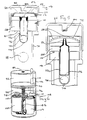
- the dispensing outlet assembly comprises a multi-part body indicated generally by arrow 10 and composed of upper and lower body parts 10a and 10b.
- the assembly further includes a modifier in the form of an annular colouring element 12, an upper valve member 14, a lower valve member 16, a weight 18 in the form of a glass ball, and a screwcap 20.
- the upper body part 10a is molded from a suitably opaque synthetic plastics material (e.g. a tinted or filled polycarbonate).
- the upper body part 10a comprises an externally screw-threaded skirt 22, an internal central annular wall 24 and an upper flange 26 having a series of arcuate slots 28 therethrough at a location disposed between the skirt 22 and the annular wall 24.
- annular recess 30 into which the slots 28 open.
- the annular recess 30 receives the annular colouring element 12.
- the flange 26 is surrounded by an upwardly and outwardly directed annular pouring lip 32.
- the slots 28 define a dispensing outlet of the assembly.
- the lower body part 10b comprises a lower sleeve 34 formed at its lower end with an inwardly directed lower flange 36 having an upwardly directed inner annular collar 38 whose upper end is inclined to define a downwardly and outwardly flaring, frusto-conical valve seat 40.
- the sleeve 34, flange 36 and collar 38 together define an annular recess 39 which surrounds the collar 38 and which is disposed below the valve seat 40.
- An inlet 41 to the assembly is defined inwardly of the flange 36 and collar 38.
- the upper end of the sleeve 34 defines an upper, frusto-conical valve seat 42 which flares outwardly and upwardly.
- the lower body part 10b has a radially outwardly directed upper flange 44 with an upwardly directed annular collar 46 spaced outwardly of the sleeve 34.
- the upper end of the sleeve 34, the flange 44 and the collar 46 together define an upper annular recess 48 which is disposed below the upper valve seat 42.
- the upper and lower body parts 10a and 10b are secured together, e.g. by frictional engagement between the outer surface of the collar 46 and the inner surface of the screw-threaded skirt 22.
- the annular colouring element 12 comprises a mass of dye particles which have been co-sprayed with a mixture of water soluble or water dispersible gums and which is contained within an annular perforated bag (not shown) formed of a woven, heat-sealable polypropylene cloth having pores over the whole of its surface, the pores having a diameter of about 70 ⁇ m.
- the annular colouring element is a 0.36 g tablet containing 100 mg of FD&C Red 40 (an azo dye), and 0.26 g of an excipient mixture of microcrystalline cellulose, maltodextrin and dextrose, giving a dye: excipients weight ratio of 1:2.6.
- the upper valve member 14 comprises a horizontal valve disk 50 having at its underside a frusto-conically chamfered outer edge which cooperates with the upper valve seat 42.
- the upper valve member 14 further comprises a multiplicity of legs 52 extending downwardly from the disk 50 to define a cage which embraces an upper region of the glass ball 18.
- the ball 18 is disposed within the sleeve 34. With the screwcap 20 removed, the valve member 50 is free to slide axially of the sleeve 34 from a lower position (as shown in Fig 2) where it seals against the valve seat 42 to an upper position in which it abuts against the lower end of the annular wall 24 of the first body part 10a.
- each leg 52 is such that the lower end thereof remains within the sleeve 34 even when the upper valve member 14 is in its upper position.
- the upper surface of the disk 50 is of convex domed shape to prevent liquid collecting on the surface thereof.
- the upper valve member 14 and upper valve seat 42 together define an upper non-return valve.
- the lower valve member 16 comprises an inverted, cup-shaped element 54 whose annular lower edge is frusto-conically shaped to correspond with that of the lower valve seat 40.
- a series of legs 56 extend upwardly from the element 54 to define a cage which embraces the lower region of the ball 18.
- the lower valve element 16 is freely slidable within the sleeve 34 so as to be movable into and out of a lower position (as shown in Fig 2) where it seals against the lower valve seat 40.
- the lower valve member 16 and the lower valve seat 40 together define a lower non-return valve.
- the screwcap 20 is formed with a central, downwardly directed post 60 of cruciform cross-section.
- the post 60 engages within the inner annular wall 24 of the upper body part 10a so as to rest against the upper, domed surface of the valve disk 50, thereby to urge the latter into its lower position in which it seals against the upper valve seat 42. This action also causes a closing force to be applied to the lower valve member 16 via the legs 52, the ball 18 and the legs 56.
- the above-described assembly is forced into the neck of a transparent bottle containing a transparent, spirit-based liquor until the flange 44 rests against the lip of the bottle.
- the outer diameter of the sleeve 34 is such that it seals within the neck of the bottle.
- the upper and lower valve members 14 and 16 are free to slide out of their sealing engagement with the respective upper and lower valve seats 42 and 40.
- liquor from the bottle passes through the inlet 41.
- the weight of liquor against the underside of the lower valve member 16 causes it to move into a position in which the liquor from the bottle can flow past the valve seat 40 and along the sleeve 34, past the upper valve seat 42 and into the interior of the upper body part 10a.
- the disk 50 of the upper valve member 14 contacts the lower edge of the inner annular wall 24 and prevents flow of liquor out of the assembly inwardly of the wall 24 i.e. it prevents flow of liquor through the space previously occupied by the post 60 of the screwcap 20.
- the annular colouring element 12 is permeable to the liquor so that the latter flows therethrough and leaves the assembly by way of one or more of the slots 28.
- the pouring lip 32 assists in preventing drips.
- the colourless liquor from the bottle leaches out some of the soluble dye from the element 12 and becomes coloured (red in the case of carmine dye).
- the liquor undergoes a colour change from colourless to red upon passage through the dispensing outlet assembly.
- the amount and physical condition of the dye in the element 12 is so arranged that it will effectively colour the liquor being dispensed in measures over a period of time until the bottle is empty. For a 70cl bottle, it is considered that a quantity of 0.1 g of the above-described dye is all that is required in the colouring element 12.
- the ball 18 acts as a mass to facilitate the required opening and closing of the valves within the assembly. This is advantageous particularly in the case of liquids containing dissolved solids, e.g. sugar, since liquid within the assembly can evaporate in time to leave a sticky deposit which may interfere with correct operation of the valves, particularly the upper valve. Shaking the bottle gently with the screwcap 20 removed enables the weight of the ball 18 to be used to release a stuck upper valve member.
- the cruciform section of the post 60 in the screwcap 20 also assists in breaking any sticky deposit between the post 60 and the wall 24 when the screwcap 20 is unscrewed.
- the dispensing outlet assembly is fitted into the neck of a bottle 70 (only partly shown) having screwcap 20.
- the assembly comprises body 10 in the form of a tubular body part 10c and four radial support ribs 10d which support the tubular part 10c centrally within the neck of the bottle 70. Spaces between the lower edges of the support ribs 10d define inlet 41, whilst a perforated insert 72 in the upper end of the neck defines outlet 28.
- the base of the tubular body part 10c is hemispherical and has an aperture 74 therethrough.
- the body part 10c contains a flexible bag 76 and a ball 78, the latter being located in the hemispherical base.
- the bag 76 has an open top which is closed by a resilient diaphragm 80 having a slit therein defining a normally closed outlet 82 to the bag 76.
- the outlet 82 is directly aligned with a central opening in the insert 72.
- a return spring (not shown) serves to bias the bag 76 and ball 78 downwardly into the position shown in Fig 4.
- the bag 76 forms a reservoir for liquid colour which is to be dispensed together with liquid from the bottle 70.
- the screwcap 20 has an internal, downwardly-extending projection 84 which is arranged to pass through the insert 72 and to engage the diaphragm 80 so as to maintain the outlet 82 closed when the screwcap 20 is fully tightened onto the neck of the bottle 70.
- the screwcap 20 is shown in a partly loosened condition.
- the spring and the action of gravity on the ball 78 serve to cause the pressure on the liquid in the bag 76 to be relaxed so that the outlet 82 can close.
- the bag 76 may re-adopt the condition shown in Fig 4.
- the arrangement may be such that the bag 76 remains in a partially collapsed state ready for further collapsing and pressurising by the spring and the ball 78 the next time the bottle 70 is tilted with the screwcap 20 removed. Any liquid which may have entered the body part 10c can drain back into the bottle 70 through the aperture 74.
- Fig 5 The embodiment of Fig 5 is very similar to that of Fig 4, except that, in this case, bag 76 has a permanently open capillary-type outlet 82 through which colour liquid is forced when the bottle 70 is tilted.
- the bag 76 is arranged to stay partially collapsed after the bottle 70 is returned to an upright position after liquid has been dispensed. This is done to ensure that the capillary outlet 82 remains filled with liquid colour.
- a motorised pump-type dispensing outlet assembly is illustrated.
- the tubular body part 10c takes the form of a cylinder housing a piston 90 which divides the tubular body part into an upper reservoir 92 for dye in gel form and a lower chamber 94.
- the radial ribs 10d are provided but are not illustrated in Fig 6.
- a screw-threaded rod 96 is mounted in the chamber 94 and engages the underside of the piston 90.
- the rod 96 has an internally screw-threaded gear ring 98 mounted thereon.
- An electric motor 100 in the chamber 94 drives the gear ring 98 via a drive gear 102 which is mounted on the output shaft of the motor 100 and which meshes with the gear ring 98.
- a battery 104 powers the motor 100 under the control of a microprocessor 106 which is connected to a sensor (not shown).
- the sensor senses when liquid is flowing past the body part 10c upon tilting of the bottle and causes the motor to be energised and senses when flow has stopped to de-energise the motor 100 via the microprocessor 106.
- An override switch 108 operated by a plunger 110 extending through the top of the body part 10c for engagement by the screwcap 20 (not shown in Fig 6) serves to ensure that the motor 100 cannot be energised when the screwcap 20 is on the bottle 70.
Landscapes
- Engineering & Computer Science (AREA)
- Mechanical Engineering (AREA)
- Surgical Instruments (AREA)
- Closures For Containers (AREA)
- Compressor (AREA)
- Valve Housings (AREA)
- Containers And Packaging Bodies Having A Special Means To Remove Contents (AREA)
- Details Of Rigid Or Semi-Rigid Containers (AREA)
- Check Valves (AREA)
- Devices For Dispensing Beverages (AREA)
- Massaging Devices (AREA)
- Noodles (AREA)
Abstract
Description
Claims (9)
- A dispensing outlet assembly for connection to a liquid container, said assembly comprising (a) a body (10) having (i) an inlet (41) for connection to the container, (ii) a dispensing outlet (28) through which liquid is dispensed from the container, and (iii) a flow passage between the inlet (41) and the outlet (28); and (b) at least one modifier (12) for modifying at least one property of the liquid being dispensed, said at least one modifier (12) being disposed in the flow passage in the body (10) so as to be contacted by the liquid passing in use from the inlet (41) to the dispensing outlet (28); characterised in that said at least one modifier (12) is selected from an additive for changing the colour of the liquid being dispensed and an additive for changing the flavour of the liquid being dispensed, whereby, in use, liquid having a colour and/or flavour which is different to that of the liquid in the container is dispensed from said dispensing outlet (28); and in that means (14,16,18) are provided for preventing liquid which has already contacted said at least modifier (12) from returning into the container.
- An assembly as claimed in claim 1, wherein said at least one modifier (12) further includes one or more of an additive for changing the mouthfeel of the liquid, an additive for changing the odour of the liquid, an additive for changing a light transmission characteristic of the liquid, a pH modifier which is arranged to induce any desired organoleptic change in the liquid, and a deodoriser for deodorising an odiferous material.
- An assembly as claimed in claim 1 or 2, wherein the preventing means (14,16,18) is a non-return valve and/or a recess disposed between said at least one modifier (12) and the inlet (41) of the body (10) so as to retain liquid which has contacted the modifier (12) in order to prevent such liquid from returning to the inlet.
- An assembly as claimed in any preceding claim, wherein said at least one modifier (12) is contained in an apertured bag (76) in said flow passage.
- An assembly as claimed in claim 4, wherein said apertured bag is a perforated bag.
- An assembly as claimed in claim 4, wherein the bag (76) is arranged to be acted upon by a part (78) which is movable when the assembly is tilted so as to cause release of a quantity of said at least one modifier from the bag (76) into the flow path.
- An assembly as claimed in any one of claims 1 to 3, including reservoir means (92) for said at least one modifier (12), and pump means (10c,90) for dispensing said at least one modifier from said reservoir (92).
- An assembly as claimed in any preceding claim, wherein the body (10) is formed of an opaque material.
- A liquid container fitted with a dispensing outlet assembly as claimed in any preceding claim.
Applications Claiming Priority (3)
| Application Number | Priority Date | Filing Date | Title |
|---|---|---|---|
| GBGB9612563.8A GB9612563D0 (en) | 1996-06-15 | 1996-06-15 | Dispensing outlet assembly |
| GB9612563 | 1996-06-15 | ||
| PCT/GB1997/001597 WO1997048617A2 (en) | 1996-06-15 | 1997-06-13 | Dispensing outlet assembly |
Publications (2)
| Publication Number | Publication Date |
|---|---|
| EP0912415A2 EP0912415A2 (en) | 1999-05-06 |
| EP0912415B1 true EP0912415B1 (en) | 2000-08-23 |
Family
ID=10795360
Family Applications (1)
| Application Number | Title | Priority Date | Filing Date |
|---|---|---|---|
| EP97926113A Expired - Lifetime EP0912415B1 (en) | 1996-06-15 | 1997-06-13 | Dispensing outlet assembly |
Country Status (12)
| Country | Link |
|---|---|
| US (1) | US6230937B1 (en) |
| EP (1) | EP0912415B1 (en) |
| AT (1) | ATE195698T1 (en) |
| AU (1) | AU720518B2 (en) |
| BR (1) | BR9709787A (en) |
| DE (1) | DE69702913D1 (en) |
| ES (1) | ES2150778T3 (en) |
| GB (1) | GB9612563D0 (en) |
| GR (1) | GR3034838T3 (en) |
| PT (1) | PT912415E (en) |
| WO (1) | WO1997048617A2 (en) |
| ZA (1) | ZA975271B (en) |
Cited By (1)
| Publication number | Priority date | Publication date | Assignee | Title |
|---|---|---|---|---|
| CN102459011A (en) * | 2009-06-11 | 2012-05-16 | J·M·斯马克公司 | Dispensing closure |
Families Citing this family (17)
| Publication number | Priority date | Publication date | Assignee | Title |
|---|---|---|---|---|
| RU2261205C2 (en) * | 2002-11-10 | 2005-09-27 | Общество с ограниченной ответственностью "ПЕРИНТ" | Bottle closure (variants) |
| ES2257141B1 (en) * | 2004-01-26 | 2007-08-16 | Alberto Recover De Frutos | IRRELLENABLE PLUG WITH WRAPPED SEAL. |
| FR2886924B1 (en) * | 2005-06-14 | 2012-08-03 | Alcan Packaging Capsules | IRREMPLISSABILITY DEVICE FOR RECOVERY TUBE, TYPICALLY BOTTLE, AND COMPOSITE BUCKET CAPSULE COMPRISING SAID DEVICE |
| US7537112B2 (en) | 2005-08-04 | 2009-05-26 | Ronald Frank Balazik | Drink mix system |
| US20090173283A1 (en) * | 2008-01-07 | 2009-07-09 | Medialore, Llc | Flow Control Device |
| GB201000815D0 (en) * | 2010-01-19 | 2010-03-03 | Brook Chrispin Samantha | Drink flavouring device |
| WO2013107860A1 (en) * | 2012-01-19 | 2013-07-25 | Technische Universität Dresden | Arrangement and method for generating accelerated particles from targets for radiotherapy |
| US9016037B2 (en) * | 2012-11-01 | 2015-04-28 | Owens-Brockway Glass Container Inc. | Container having a dissolvable dispense indicator |
| US9795242B2 (en) | 2013-02-14 | 2017-10-24 | Cirkul, Inc. | Additive delivery systems and containers |
| US9145240B2 (en) * | 2013-04-25 | 2015-09-29 | Owens-Brockway Glass Container Inc. | Container fitment |
| WO2015042518A1 (en) * | 2013-09-20 | 2015-03-26 | Closure Systems International Inc. | Anti-refill closure assembly |
| US10392178B2 (en) * | 2014-04-21 | 2019-08-27 | Zen Potion, Inc. | Preparing beverages containing cannabinoids using beverage containers with polymer matrices |
| US10888826B2 (en) | 2014-11-21 | 2021-01-12 | Cirkul, Inc. | Adjustable additive cartridge systems and methods |
| ES2748334T3 (en) | 2014-11-21 | 2020-03-16 | Cirkul Inc | Adjustable Additive Cartridge Systems |
| US12017191B2 (en) | 2017-03-06 | 2024-06-25 | Cirkul, Inc. | Adjustable additive delivery systems and dispensing closure valves for the same |
| CN113955320B (en) * | 2021-10-11 | 2023-08-01 | 天津煊宇包装制品有限公司 | Plastic bottle for beverage |
| US20250019134A1 (en) * | 2021-11-23 | 2025-01-16 | Torrent Innova, S.L. | Valve for pourer |
Family Cites Families (6)
| Publication number | Priority date | Publication date | Assignee | Title |
|---|---|---|---|---|
| US3073469A (en) * | 1959-12-07 | 1963-01-15 | Edward J Towns | Non-refillable closure devices for bottles |
| US2975925A (en) * | 1960-01-19 | 1961-03-21 | Glenn M Chambers | Container attachment for pop bottles |
| IT1137589B (en) * | 1981-05-12 | 1986-09-10 | Guala Angelo Spa | CLOSURE WITH INTERNAL GUARANTEE FOR BOTTLES AND SIMILAR |
| LU86368A1 (en) * | 1986-03-24 | 1987-11-11 | Oreal | PROCESS FOR PREPARING AND DISPENSING A PRODUCT COMPRISING AT LEAST TWO COMPONENTS, AND DEVICE FOR IMPLEMENTING SAME |
| AU685110B2 (en) * | 1993-07-08 | 1998-01-15 | Monsanto Europe S.A. | Improved closure for liquid containing containers |
| NL9401491A (en) * | 1994-09-14 | 1996-04-01 | Hoytink Holding Bv | Pouring spout. |
-
1996
- 1996-06-15 GB GBGB9612563.8A patent/GB9612563D0/en active Pending
-
1997
- 1997-06-13 ZA ZA975271A patent/ZA975271B/en unknown
- 1997-06-13 WO PCT/GB1997/001597 patent/WO1997048617A2/en not_active Ceased
- 1997-06-13 PT PT97926113T patent/PT912415E/en unknown
- 1997-06-13 EP EP97926113A patent/EP0912415B1/en not_active Expired - Lifetime
- 1997-06-13 DE DE69702913T patent/DE69702913D1/en not_active Expired - Lifetime
- 1997-06-13 AU AU30998/97A patent/AU720518B2/en not_active Ceased
- 1997-06-13 ES ES97926113T patent/ES2150778T3/en not_active Expired - Lifetime
- 1997-06-13 BR BR9709787-0A patent/BR9709787A/en not_active IP Right Cessation
- 1997-06-13 US US09/202,513 patent/US6230937B1/en not_active Expired - Fee Related
- 1997-06-13 AT AT97926113T patent/ATE195698T1/en active
-
2000
- 2000-11-13 GR GR20000402526T patent/GR3034838T3/en unknown
Cited By (3)
| Publication number | Priority date | Publication date | Assignee | Title |
|---|---|---|---|---|
| CN102459011A (en) * | 2009-06-11 | 2012-05-16 | J·M·斯马克公司 | Dispensing closure |
| US9010590B2 (en) | 2009-06-11 | 2015-04-21 | The J.M. Smucker Company | Dispensing closure |
| CN102459011B (en) * | 2009-06-11 | 2017-05-10 | J·M·斯马克公司 | Dispensing closure |
Also Published As
| Publication number | Publication date |
|---|---|
| AU3099897A (en) | 1998-01-07 |
| DE69702913D1 (en) | 2000-09-28 |
| PT912415E (en) | 2001-01-31 |
| WO1997048617A2 (en) | 1997-12-24 |
| GR3034838T3 (en) | 2001-02-28 |
| ES2150778T3 (en) | 2000-12-01 |
| EP0912415A2 (en) | 1999-05-06 |
| HK1019433A1 (en) | 2000-02-11 |
| ZA975271B (en) | 1998-07-10 |
| BR9709787A (en) | 2000-01-11 |
| ATE195698T1 (en) | 2000-09-15 |
| AU720518B2 (en) | 2000-06-01 |
| GB9612563D0 (en) | 1996-08-21 |
| WO1997048617A3 (en) | 1998-03-12 |
| US6230937B1 (en) | 2001-05-15 |
Similar Documents
| Publication | Publication Date | Title |
|---|---|---|
| US6230937B1 (en) | Dispensing outlet assembly | |
| US4420100A (en) | Dispensing apparatus | |
| US6644471B1 (en) | Dispensing capsule for a liquid container | |
| US4044923A (en) | Foam generating dispenser having a movable and stationary porous element | |
| AU2003249558B2 (en) | A portable beverage preparation device and system | |
| CA1302367C (en) | Container closure cap with metering appliance | |
| US4239132A (en) | Apparatus for facilitating inflow through closure threads of dispenser | |
| US3998364A (en) | Dispensing valve for bottled carbonated beverages | |
| AU722914B2 (en) | Dispenser | |
| US4408702A (en) | Automatic dispenser cap | |
| HUE029753T2 (en) | Closed capsule with opening means | |
| US20040011679A1 (en) | Closure with selectively operable dispense feature | |
| US20050263414A1 (en) | Dispensing capsule | |
| KR101116526B1 (en) | Machine for the preparation of beverages | |
| EP0011394B1 (en) | Dispensing apparatus | |
| HK1019433B (en) | Dispensing outlet assembly | |
| US6095886A (en) | Toy nursing bottle | |
| US20180311108A1 (en) | Pill coating apparatus and method | |
| AU737696B3 (en) | A dispensing cap | |
| CA1104532A (en) | Dispensing apparatus | |
| FR3164187A1 (en) | Aroma diffuser for disposable water bottle | |
| FR3164186A1 (en) | Aroma diffuser for disposable water bottle | |
| FR3164188A1 (en) | Aroma diffuser for disposable water bottle | |
| FR3164192A1 (en) | Aroma diffuser for disposable water bottle | |
| AU717820B3 (en) | Dispenser |
Legal Events
| Date | Code | Title | Description |
|---|---|---|---|
| PUAI | Public reference made under article 153(3) epc to a published international application that has entered the european phase |
Free format text: ORIGINAL CODE: 0009012 |
|
| 17P | Request for examination filed |
Effective date: 19981207 |
|
| AK | Designated contracting states |
Kind code of ref document: A2 Designated state(s): AT CH DE ES FR GB GR IE IT LI NL PT |
|
| 17Q | First examination report despatched |
Effective date: 19990507 |
|
| GRAG | Despatch of communication of intention to grant |
Free format text: ORIGINAL CODE: EPIDOS AGRA |
|
| GRAG | Despatch of communication of intention to grant |
Free format text: ORIGINAL CODE: EPIDOS AGRA |
|
| GRAH | Despatch of communication of intention to grant a patent |
Free format text: ORIGINAL CODE: EPIDOS IGRA |
|
| GRAH | Despatch of communication of intention to grant a patent |
Free format text: ORIGINAL CODE: EPIDOS IGRA |
|
| RIN1 | Information on inventor provided before grant (corrected) |
Inventor name: KENDLE, HEATHER Inventor name: OGLE, SIMON Inventor name: STREETER, ANDREW COLIN Inventor name: PURDEY, COLIN Inventor name: SHILTON, ANDREW Inventor name: HATCH, JULIE Inventor name: JOHNSON, DAVID |
|
| GRAA | (expected) grant |
Free format text: ORIGINAL CODE: 0009210 |
|
| AK | Designated contracting states |
Kind code of ref document: B1 Designated state(s): AT CH DE ES FR GB GR IE IT LI NL PT |
|
| PG25 | Lapsed in a contracting state [announced via postgrant information from national office to epo] |
Ref country code: LI Free format text: LAPSE BECAUSE OF FAILURE TO SUBMIT A TRANSLATION OF THE DESCRIPTION OR TO PAY THE FEE WITHIN THE PRESCRIBED TIME-LIMIT Effective date: 20000823 Ref country code: CH Free format text: LAPSE BECAUSE OF FAILURE TO SUBMIT A TRANSLATION OF THE DESCRIPTION OR TO PAY THE FEE WITHIN THE PRESCRIBED TIME-LIMIT Effective date: 20000823 Ref country code: AT Free format text: LAPSE BECAUSE OF FAILURE TO SUBMIT A TRANSLATION OF THE DESCRIPTION OR TO PAY THE FEE WITHIN THE PRESCRIBED TIME-LIMIT Effective date: 20000823 |
|
| REF | Corresponds to: |
Ref document number: 195698 Country of ref document: AT Date of ref document: 20000915 Kind code of ref document: T |
|
| REG | Reference to a national code |
Ref country code: CH Ref legal event code: EP |
|
| REG | Reference to a national code |
Ref country code: IE Ref legal event code: FG4D |
|
| REF | Corresponds to: |
Ref document number: 69702913 Country of ref document: DE Date of ref document: 20000928 |
|
| ET | Fr: translation filed | ||
| ITF | It: translation for a ep patent filed | ||
| PG25 | Lapsed in a contracting state [announced via postgrant information from national office to epo] |
Ref country code: DE Free format text: LAPSE BECAUSE OF FAILURE TO SUBMIT A TRANSLATION OF THE DESCRIPTION OR TO PAY THE FEE WITHIN THE PRESCRIBED TIME-LIMIT Effective date: 20001124 |
|
| REG | Reference to a national code |
Ref country code: ES Ref legal event code: FG2A Ref document number: 2150778 Country of ref document: ES Kind code of ref document: T3 |
|
| REG | Reference to a national code |
Ref country code: PT Ref legal event code: SC4A Free format text: AVAILABILITY OF NATIONAL TRANSLATION Effective date: 20001012 |
|
| REG | Reference to a national code |
Ref country code: CH Ref legal event code: PL |
|
| PLBE | No opposition filed within time limit |
Free format text: ORIGINAL CODE: 0009261 |
|
| STAA | Information on the status of an ep patent application or granted ep patent |
Free format text: STATUS: NO OPPOSITION FILED WITHIN TIME LIMIT |
|
| 26N | No opposition filed | ||
| REG | Reference to a national code |
Ref country code: GB Ref legal event code: IF02 |
|
| PGFP | Annual fee paid to national office [announced via postgrant information from national office to epo] |
Ref country code: NL Payment date: 20090603 Year of fee payment: 13 Ref country code: IE Payment date: 20090618 Year of fee payment: 13 |
|
| PGFP | Annual fee paid to national office [announced via postgrant information from national office to epo] |
Ref country code: PT Payment date: 20090615 Year of fee payment: 13 Ref country code: IT Payment date: 20090616 Year of fee payment: 13 |
|
| PGFP | Annual fee paid to national office [announced via postgrant information from national office to epo] |
Ref country code: ES Payment date: 20090709 Year of fee payment: 13 |
|
| PGFP | Annual fee paid to national office [announced via postgrant information from national office to epo] |
Ref country code: GR Payment date: 20090514 Year of fee payment: 13 Ref country code: GB Payment date: 20090610 Year of fee payment: 13 |
|
| REG | Reference to a national code |
Ref country code: PT Ref legal event code: MM4A Free format text: LAPSE DUE TO NON-PAYMENT OF FEES Effective date: 20101213 |
|
| REG | Reference to a national code |
Ref country code: NL Ref legal event code: V1 Effective date: 20110101 |
|
| GBPC | Gb: european patent ceased through non-payment of renewal fee |
Effective date: 20100613 |
|
| PG25 | Lapsed in a contracting state [announced via postgrant information from national office to epo] |
Ref country code: PT Free format text: LAPSE BECAUSE OF NON-PAYMENT OF DUE FEES Effective date: 20101213 |
|
| REG | Reference to a national code |
Ref country code: FR Ref legal event code: ST Effective date: 20110228 |
|
| REG | Reference to a national code |
Ref country code: IE Ref legal event code: MM4A |
|
| PG25 | Lapsed in a contracting state [announced via postgrant information from national office to epo] |
Ref country code: IT Free format text: LAPSE BECAUSE OF NON-PAYMENT OF DUE FEES Effective date: 20100613 |
|
| PG25 | Lapsed in a contracting state [announced via postgrant information from national office to epo] |
Ref country code: IE Free format text: LAPSE BECAUSE OF NON-PAYMENT OF DUE FEES Effective date: 20100614 |
|
| PG25 | Lapsed in a contracting state [announced via postgrant information from national office to epo] |
Ref country code: FR Free format text: LAPSE BECAUSE OF NON-PAYMENT OF DUE FEES Effective date: 20100630 Ref country code: NL Free format text: LAPSE BECAUSE OF NON-PAYMENT OF DUE FEES Effective date: 20110101 |
|
| PG25 | Lapsed in a contracting state [announced via postgrant information from national office to epo] |
Ref country code: GR Free format text: LAPSE BECAUSE OF NON-PAYMENT OF DUE FEES Effective date: 20110104 |
|
| REG | Reference to a national code |
Ref country code: ES Ref legal event code: FD2A Effective date: 20110715 |
|
| PG25 | Lapsed in a contracting state [announced via postgrant information from national office to epo] |
Ref country code: ES Free format text: LAPSE BECAUSE OF NON-PAYMENT OF DUE FEES Effective date: 20110705 Ref country code: GB Free format text: LAPSE BECAUSE OF NON-PAYMENT OF DUE FEES Effective date: 20100613 |
|
| PG25 | Lapsed in a contracting state [announced via postgrant information from national office to epo] |
Ref country code: ES Free format text: LAPSE BECAUSE OF NON-PAYMENT OF DUE FEES Effective date: 20100614 |
|
| PGFP | Annual fee paid to national office [announced via postgrant information from national office to epo] |
Ref country code: FR Payment date: 20090611 Year of fee payment: 13 |
|
| REG | Reference to a national code |
Ref country code: GR Ref legal event code: ML Ref document number: 20000402526 Country of ref document: GR Effective date: 20110104 |