EP0911085B1 - A spray gumming unit - Google Patents
A spray gumming unit Download PDFInfo
- Publication number
- EP0911085B1 EP0911085B1 EP98830607A EP98830607A EP0911085B1 EP 0911085 B1 EP0911085 B1 EP 0911085B1 EP 98830607 A EP98830607 A EP 98830607A EP 98830607 A EP98830607 A EP 98830607A EP 0911085 B1 EP0911085 B1 EP 0911085B1
- Authority
- EP
- European Patent Office
- Prior art keywords
- ejector
- spray
- pad
- cleaning
- unit
- Prior art date
- Legal status (The legal status is an assumption and is not a legal conclusion. Google has not performed a legal analysis and makes no representation as to the accuracy of the status listed.)
- Expired - Lifetime
Links
- 239000007921 spray Substances 0.000 title claims description 16
- 239000000853 adhesive Substances 0.000 claims description 13
- 230000001070 adhesive effect Effects 0.000 claims description 13
- 239000007788 liquid Substances 0.000 claims description 12
- 239000000126 substance Substances 0.000 claims description 9
- 238000004140 cleaning Methods 0.000 claims description 7
- 238000012856 packing Methods 0.000 description 3
- 238000001035 drying Methods 0.000 description 1
- 238000012423 maintenance Methods 0.000 description 1
- 238000004806 packaging method and process Methods 0.000 description 1
- 230000002441 reversible effect Effects 0.000 description 1
- 239000002904 solvent Substances 0.000 description 1
- XLYOFNOQVPJJNP-UHFFFAOYSA-N water Substances O XLYOFNOQVPJJNP-UHFFFAOYSA-N 0.000 description 1
- 238000009736 wetting Methods 0.000 description 1
Images
Classifications
-
- B—PERFORMING OPERATIONS; TRANSPORTING
- B05—SPRAYING OR ATOMISING IN GENERAL; APPLYING FLUENT MATERIALS TO SURFACES, IN GENERAL
- B05B—SPRAYING APPARATUS; ATOMISING APPARATUS; NOZZLES
- B05B15/00—Details of spraying plant or spraying apparatus not otherwise provided for; Accessories
- B05B15/50—Arrangements for cleaning; Arrangements for preventing deposits, drying-out or blockage; Arrangements for detecting improper discharge caused by the presence of foreign matter
- B05B15/52—Arrangements for cleaning; Arrangements for preventing deposits, drying-out or blockage; Arrangements for detecting improper discharge caused by the presence of foreign matter for removal of clogging particles
Definitions
- the present invention relates to a spray gumming unit.
- the invention can be used to good advantage in the field of packaging machinery, especially packing. machines, to which the description below refers but without thereby restricting the scope of the invention.
- an adhesive substance must be applied to certain parts of paper sheets, such as blanks, for example, designed to be folded into containers or packets, or labels to be applied to the containers or packets.
- Packing machines are known to be equipped with spray gumming units facing the line along which the paper sheets to be gummed are fed, each unit comprising at least one spray gummer whose gumming nozzle is connected to an adhesive feed system and is equipped with an adhesive ejector.
- spray gumming units of this type require frequent cleaning and maintenance, mainly because part of the adhesive dries on the ejectors when the packing machine is stopped for short periods.
- the aim of the present invention is to provide a spray gumming unit that overcomes the disadvantage just described.
- the present invention provides a spray gumming unit as described in claim 1.
- the numeral 1 indicates a spray gumming unit comprising two spray gummers 2, each having a gumming nozzle 3 equipped with an ejector 4 facing a line (not illustrated) along which sheets of paper to be gummed (not illustrated) are fed.
- the gummers 2 are mounted by a bracket 5 and each has an infeed pipe 6 connected through a valve 7 to an adhesive 9 feed system 8, the adhesive being contained in a tank 10 and delivered by a pump 11.
- the unit 1 also comprises a shutter device 12 which in turn comprises a supporting element consisting of a rod 13, a portion of which, consisting of an end 14, is rigidly connected to a plate 15 which mounts a pad 16, made preferably of sponge, and whose opposite end 17 is keyed to a shaft 18 of a reversible motor 19 mounted in a fixed position by a bracket 20.
- a shutter device 12 which in turn comprises a supporting element consisting of a rod 13, a portion of which, consisting of an end 14, is rigidly connected to a plate 15 which mounts a pad 16, made preferably of sponge, and whose opposite end 17 is keyed to a shaft 18 of a reversible motor 19 mounted in a fixed position by a bracket 20.
- the motor 19 is driven in such a way as to swing the rod 13, clockwise and counterclockwise in Fig.1, about the axis 18a of the shaft 18, away from and towards the ejectors 4, from an open position A, illustrated as a dashed line in Fig. 1, in which the plate 15 is located on one side of the ejectors 4, and a closed position C, illustrated as a continuous line in Fig. 1, in which the plate 15 is face to face with the nozzles 3 with the pad 16 in contact with the ejectors 4 and closing the ejectors 4 themselves.
- the unit 1 also comprises a device 21 that supplies a liquid substance 22, for example, water or solvent, and that comprises a battery of nebulizing nozzles 23.
- the nozzles 23 are placed face to face with the plate 15 in position A, and are designed to spray the substance 2 onto the pad 16, thus wetting the pad 16 and cleaning it.
- the spray device 21 is mounted by a bracket 24 and has an infeed pipe 25 connected through a valve 26 to a system 27 that feeds the liquid substance 22, the liquid substance being contained in a tank 28 and delivered by a pump 29.
- the unit 1 comprises a control unit 30, which, when the unit 1 is not operating, controls the drive of the motor 19 of the valve 7 of the adhesive 9 feed system 8 and of the valve 26 of the liquid system 22 feed system 27.
- the rod 13 of the shutter device 12 is in the open position A and the control unit 30 receives a signal each time a sheet of paper to be gummed passes in front of the ejectors 4 of the gummers 2 and opens the valve 7 to allow the adhesive 9 to be sprayed out of the ejectors 4.
- control unit 30 closes the valve 7, thus cutting off the supply of adhesive 9, and opens the valve 26 of the liquid 22 feed system 27 so that jets of nebulized liquid 22 are sprayed out of the nozzles 23 and wet the pad 16.
- control unit 30 activates the motor 19, thus swinging the rod 13 from position A to position C so that the pad 16 wetted by the liquid 22 moves into contact with the ejectors 4 and the latter are closed by the pad 16.
- control unit 30 drives the motor 19 so as to move the rod 13 to position A and opens the valve 27 so that the pad 16 is again sprayed with nebulized liquid 22 to clean the pad 16 once again.
Landscapes
- Coating Apparatus (AREA)
- Agricultural Chemicals And Associated Chemicals (AREA)
- Containers And Packaging Bodies Having A Special Means To Remove Contents (AREA)
- Materials For Medical Uses (AREA)
- Absorbent Articles And Supports Therefor (AREA)
- Making Paper Articles (AREA)
Description
- The present invention relates to a spray gumming unit.
- The invention can be used to good advantage in the field of packaging machinery, especially packing. machines, to which the description below refers but without thereby restricting the scope of the invention.
- In these machines, an adhesive substance must be applied to certain parts of paper sheets, such as blanks, for example, designed to be folded into containers or packets, or labels to be applied to the containers or packets.
- Packing machines are known to be equipped with spray gumming units facing the line along which the paper sheets to be gummed are fed, each unit comprising at least one spray gummer whose gumming nozzle is connected to an adhesive feed system and is equipped with an adhesive ejector.
- The disadvantage of spray gumming units of this type is that the gumming nozzle ejectors require frequent cleaning and maintenance, mainly because part of the adhesive dries on the ejectors when the packing machine is stopped for short periods.
- The aim of the present invention is to provide a spray gumming unit that overcomes the disadvantage just described.
- The present invention provides a spray gumming unit as described in
claim 1. - Such devices are known from JP-A-1 262 964 or from US-A-4 387 002.
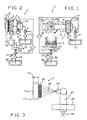
- The invention will now be described with reference to the accompanying drawings which illustrate a preferred embodiment of the invention and in which:
- Figure 1 is a front elevation view, with some parts cut away in order to better illustrate others of a preferred embodiment of the spray gumming unit made according to the present invention;
- Figure 2 is a side view of the unit illustrated in Fig. 1; and
- Figure 3 is an enlarged detail of a part of Fig. 2.
- With reference to Figs. 1 and 2, the
numeral 1 indicates a spray gumming unit comprising twospray gummers 2, each having agumming nozzle 3 equipped with an ejector 4 facing a line (not illustrated) along which sheets of paper to be gummed (not illustrated) are fed. - As shown in Fig. 2, the
gummers 2 are mounted by a bracket 5 and each has an infeedpipe 6 connected through a valve 7 to an adhesive 9 feed system 8, the adhesive being contained in atank 10 and delivered by apump 11. - As illustrated in Fig. 1, the
unit 1 also comprises ashutter device 12 which in turn comprises a supporting element consisting of arod 13, a portion of which, consisting of anend 14, is rigidly connected to aplate 15 which mounts apad 16, made preferably of sponge, and whoseopposite end 17 is keyed to ashaft 18 of areversible motor 19 mounted in a fixed position by abracket 20. - The
motor 19 is driven in such a way as to swing therod 13, clockwise and counterclockwise in Fig.1, about the axis 18a of theshaft 18, away from and towards the ejectors 4, from an open position A, illustrated as a dashed line in Fig. 1, in which theplate 15 is located on one side of the ejectors 4, and a closed position C, illustrated as a continuous line in Fig. 1, in which theplate 15 is face to face with thenozzles 3 with thepad 16 in contact with the ejectors 4 and closing the ejectors 4 themselves. - As shown in Figs. 1 and 3, the
unit 1 also comprises adevice 21 that supplies aliquid substance 22, for example, water or solvent, and that comprises a battery of nebulizingnozzles 23. Thenozzles 23 are placed face to face with theplate 15 in position A, and are designed to spray thesubstance 2 onto thepad 16, thus wetting thepad 16 and cleaning it. - The
spray device 21 is mounted by abracket 24 and has an infeedpipe 25 connected through a valve 26 to a system 27 that feeds theliquid substance 22, the liquid substance being contained in atank 28 and delivered by apump 29. - Lastly, the
unit 1 comprises acontrol unit 30, which, when theunit 1 is not operating, controls the drive of themotor 19 of the valve 7 of the adhesive 9 feed system 8 and of the valve 26 of theliquid system 22 feed system 27. - During a normal operating cycle of the
gumming unit 1, therod 13 of theshutter device 12 is in the open position A and thecontrol unit 30 receives a signal each time a sheet of paper to be gummed passes in front of the ejectors 4 of thegummers 2 and opens the valve 7 to allow the adhesive 9 to be sprayed out of the ejectors 4. - If operation is stopped, the
control unit 30 closes the valve 7, thus cutting off the supply of adhesive 9, and opens the valve 26 of theliquid 22 feed system 27 so that jets ofnebulized liquid 22 are sprayed out of thenozzles 23 and wet thepad 16. - At this point, after closing the valve 26, the
control unit 30 activates themotor 19, thus swinging therod 13 from position A to position C so that thepad 16 wetted by theliquid 22 moves into contact with the ejectors 4 and the latter are closed by thepad 16. - Note that when the
pad 16 wetted by theliquid 22 is in contact with the ejectors 4, it prevents the adhesive 9 from drying on and clogging the ejectors 4. - When the operating cycle is resumed, before the adhesive 9 starts being fed to the
gummers 2 again, thecontrol unit 30 drives themotor 19 so as to move therod 13 to position A and opens the valve 27 so that thepad 16 is again sprayed withnebulized liquid 22 to clean thepad 16 once again.
Claims (4)
- A spray gumming unit comprising: a system (8) for feeding an adhesive substance (9); at least one spray gummer (2) with a gumming nozzle (3) equipped with an ejector (4) for the adhesive substance (9); shutter means (12) that close the ejector (4) during stops in gumming operations, the shutter means (12) being capable of moving, during the stops, away from and towards the ejector (4) between a position (A) in which the ejector (4) is open to a position (C) in which it is closed; motor means (19) to move the shutter means (12) to and from the open position (A) and closed position (C); and means (21) for cleaning the shutter means (12) when they are in the open position (A);
the unit being chraracterized in that said shutter means (12) in the respective open position (A) is disposed in front of said means (21) for cleaning and spaced from the ejector (4), while in the respective closed position (C) the shutter means (12) is spaced from the means (21) for cleaning and disposed in front of the ejector (4). - The unit according to claim 1 characterized in that the shutter means (12) comprise a supporting element (13) designed to move to and from the open position (A) to the closed position (C); a portion (14) of the supporting element (13) having connected to it means (15) for mounting a pad (16) which, in the closed position (C), is in contact with the ejector (4) so as to close the ejector (4) and, in the open position (A), can be cleaned by the cleaning means (21).
- The unit according to claim 2 characterized in that the cleaning means (21) comprise means (21) that deliver a liquid substance (22) and spray the liquid (22) on the pad (16) so as to wet and/or clean the pad (16) itself.
- The unit according to claim 3 characterized in that the delivery means (21) comprise nebulizing means (23) that spray the liquid substance (22) on the pad (16).
Applications Claiming Priority (2)
| Application Number | Priority Date | Filing Date | Title |
|---|---|---|---|
| ITBO970639 | 1997-10-27 | ||
| IT97BO000639A IT1298677B1 (en) | 1997-10-27 | 1997-10-27 | SPRAY RUBBER UNIT. |
Publications (2)
| Publication Number | Publication Date |
|---|---|
| EP0911085A1 EP0911085A1 (en) | 1999-04-28 |
| EP0911085B1 true EP0911085B1 (en) | 2004-02-25 |
Family
ID=11342613
Family Applications (1)
| Application Number | Title | Priority Date | Filing Date |
|---|---|---|---|
| EP98830607A Expired - Lifetime EP0911085B1 (en) | 1997-10-27 | 1998-10-13 | A spray gumming unit |
Country Status (5)
| Country | Link |
|---|---|
| US (1) | US6116518A (en) |
| EP (1) | EP0911085B1 (en) |
| CN (1) | CN1215633A (en) |
| DE (1) | DE69821859T2 (en) |
| IT (1) | IT1298677B1 (en) |
Families Citing this family (8)
| Publication number | Priority date | Publication date | Assignee | Title |
|---|---|---|---|---|
| IT1311388B1 (en) * | 1999-11-10 | 2002-03-12 | Gd Spa | SPRAY RUBBER UNIT. |
| FI108781B (en) * | 2000-09-04 | 2002-03-28 | Admets Oy | Equipment for preventing the nozzle of a liquid dispensing device from drying out |
| ITBO20010078A1 (en) * | 2001-02-14 | 2002-08-14 | Gd Spa | SPRAY RUBBER UNIT |
| ES2197765B2 (en) * | 2001-08-17 | 2005-03-16 | Asm-Dimatec Ingenieria, S.A. | NOZZLE CLEANING MACHINE WITH PAPER. |
| CN100561272C (en) * | 2006-07-12 | 2009-11-18 | 鸿富锦精密工业(深圳)有限公司 | Rubber cartridge fixing device and dispensing device |
| ITUD20120132A1 (en) | 2012-07-20 | 2014-01-21 | Cps Color Equipment S P A Con Unic O Socio | DEVICE TO PREVENT DRYING OF NOZZLES OF A MACHINE TO PREPARE FLUID DYES PRODUCTS |
| US11355366B2 (en) * | 2018-08-30 | 2022-06-07 | Taiwan Semiconductor Manufacturing Co., Ltd. | Systems and methods for shuttered wafer cleaning |
| CN114030709A (en) * | 2021-11-11 | 2022-02-11 | 干将新材料有限公司 | Processing mechanism of paste formula deoxidier and packagine machine that has this mechanism thereof |
Family Cites Families (10)
| Publication number | Priority date | Publication date | Assignee | Title |
|---|---|---|---|---|
| DE3012371C2 (en) * | 1980-03-29 | 1983-06-30 | Maschinenfabrik Alfred Schmermund Gmbh & Co, 5820 Gevelsberg | Glue applicator |
| JPH01262964A (en) * | 1988-04-15 | 1989-10-19 | Hitachi Ltd | automatic nozzle cleaner |
| DE3908453A1 (en) * | 1989-03-15 | 1990-09-20 | Mf Applikationstechnik Gmbh | Process and apparatus for the discontinuous delivery of application liquids solidifying in air from application nozzles |
| DE3915549A1 (en) * | 1989-05-12 | 1990-11-22 | Sprimag Spritzmaschbau Gmbh | Automatic paint spraying installation - has system to clean spray nozzle before beginning of each spraying operation |
| DE9004733U1 (en) * | 1990-04-26 | 1990-06-28 | hhs Leimauftrags-Systeme GmbH, 40885 Ratingen | Dosing valve with carrying device |
| US5065692A (en) * | 1990-04-30 | 1991-11-19 | At&T Bell Laboratories | Solder flux applicator |
| US5240502A (en) * | 1990-11-13 | 1993-08-31 | Mactron, Inc. | Improvement in apparatus for applying a coating to a moving surface |
| US5226565A (en) * | 1991-10-07 | 1993-07-13 | The Dow Chemical Company | Cleaning attachment for nozzles |
| US5344073A (en) * | 1992-04-29 | 1994-09-06 | Nordson Corporation | Nozzle cleaning system including spray gun cover for can coating system |
| IT1283307B1 (en) * | 1996-03-27 | 1998-04-16 | Corob Srl | HUMIDIFIER DEVICE FOR FLUID DISPENSING NOZZLES OF A DISPENSING MACHINE. |
-
1997
- 1997-10-27 IT IT97BO000639A patent/IT1298677B1/en active IP Right Grant
-
1998
- 1998-10-13 EP EP98830607A patent/EP0911085B1/en not_active Expired - Lifetime
- 1998-10-13 DE DE69821859T patent/DE69821859T2/en not_active Expired - Lifetime
- 1998-10-26 US US09/178,609 patent/US6116518A/en not_active Expired - Lifetime
- 1998-10-27 CN CN98123465A patent/CN1215633A/en active Pending
Also Published As
| Publication number | Publication date |
|---|---|
| DE69821859D1 (en) | 2004-04-01 |
| DE69821859T2 (en) | 2004-12-09 |
| US6116518A (en) | 2000-09-12 |
| EP0911085A1 (en) | 1999-04-28 |
| IT1298677B1 (en) | 2000-01-12 |
| ITBO970639A0 (en) | 1997-10-27 |
| ITBO970639A1 (en) | 1999-04-27 |
| CN1215633A (en) | 1999-05-05 |
Similar Documents
| Publication | Publication Date | Title |
|---|---|---|
| US6607145B1 (en) | Spray gumming unit | |
| US7976656B2 (en) | Gumming device and a method for gumming a web of wrapping material | |
| JP3556870B2 (en) | Cigarette wrapping machine | |
| EP1213431A3 (en) | Controlled dispensing of material | |
| US6116518A (en) | Spray gumming unit | |
| ITBO20010078A1 (en) | SPRAY RUBBER UNIT | |
| EP2234893A1 (en) | Labeling method and apparatus | |
| US5729855A (en) | Bowling lane conditioning machine with single head dispenser | |
| KR101140427B1 (en) | Improvements relating to material application to rod wrappers | |
| EP1121869B1 (en) | A gumming unit | |
| US20050217700A1 (en) | Method for applying cleaning liquid to a bowling lane using a reciprocating dispensing head | |
| US5230736A (en) | Apparatus for applying adhesive to one side of a porous web | |
| EP1016550B1 (en) | Method and apparatus for moistening envelope flaps | |
| EP1109626B1 (en) | A device for cleaning a gumming applicator | |
| US20070227672A1 (en) | Apparatus for preparing roll of paper | |
| US6558467B1 (en) | Tape dispensing apparatus with improved adhesive reactivation | |
| EP1219540B1 (en) | Method, assembly and unit for gumming articles | |
| KR101731870B1 (en) | Machine of adhesives spreading apparatus for box base paper connecting | |
| JP3990134B2 (en) | Dispenser device for dry fluid | |
| US6613149B1 (en) | Banderole gluing apparatus and method | |
| JPH03133719A (en) | Pasting device | |
| JPS60114372A (en) | Gluing device | |
| KR200284511Y1 (en) | Device for Attaching Tie on the Packs | |
| JP7454841B2 (en) | Printer | |
| CN214266790U (en) | Front end humidifying device for full-automatic box pasting machine |
Legal Events
| Date | Code | Title | Description |
|---|---|---|---|
| PUAI | Public reference made under article 153(3) epc to a published international application that has entered the european phase |
Free format text: ORIGINAL CODE: 0009012 |
|
| AK | Designated contracting states |
Kind code of ref document: A1 Designated state(s): DE FR GB IT |
|
| AX | Request for extension of the european patent |
Free format text: AL;LT;LV;MK;RO;SI |
|
| 17P | Request for examination filed |
Effective date: 19990810 |
|
| AKX | Designation fees paid |
Free format text: DE FR GB IT |
|
| 17Q | First examination report despatched |
Effective date: 20021015 |
|
| GRAP | Despatch of communication of intention to grant a patent |
Free format text: ORIGINAL CODE: EPIDOSNIGR1 |
|
| GRAS | Grant fee paid |
Free format text: ORIGINAL CODE: EPIDOSNIGR3 |
|
| GRAA | (expected) grant |
Free format text: ORIGINAL CODE: 0009210 |
|
| RAP1 | Party data changed (applicant data changed or rights of an application transferred) |
Owner name: G.D S.P.A. |
|
| AK | Designated contracting states |
Kind code of ref document: B1 Designated state(s): DE FR GB IT |
|
| REG | Reference to a national code |
Ref country code: GB Ref legal event code: FG4D |
|
| REF | Corresponds to: |
Ref document number: 69821859 Country of ref document: DE Date of ref document: 20040401 Kind code of ref document: P |
|
| ET | Fr: translation filed | ||
| PLBE | No opposition filed within time limit |
Free format text: ORIGINAL CODE: 0009261 |
|
| STAA | Information on the status of an ep patent application or granted ep patent |
Free format text: STATUS: NO OPPOSITION FILED WITHIN TIME LIMIT |
|
| 26N | No opposition filed |
Effective date: 20041126 |
|
| PG25 | Lapsed in a contracting state [announced via postgrant information from national office to epo] |
Ref country code: IT Free format text: LAPSE BECAUSE OF NON-PAYMENT OF DUE FEES;WARNING: LAPSES OF ITALIAN PATENTS WITH EFFECTIVE DATE BEFORE 2007 MAY HAVE OCCURRED AT ANY TIME BEFORE 2007. THE CORRECT EFFECTIVE DATE MAY BE DIFFERENT FROM THE ONE RECORDED. Effective date: 20051013 |
|
| REG | Reference to a national code |
Ref country code: FR Ref legal event code: ST Effective date: 20080630 |
|
| PGFP | Annual fee paid to national office [announced via postgrant information from national office to epo] |
Ref country code: FR Payment date: 20061017 Year of fee payment: 9 |
|
| PG25 | Lapsed in a contracting state [announced via postgrant information from national office to epo] |
Ref country code: FR Free format text: LAPSE BECAUSE OF NON-PAYMENT OF DUE FEES Effective date: 20071031 |
|
| PGFP | Annual fee paid to national office [announced via postgrant information from national office to epo] |
Ref country code: DE Payment date: 20101027 Year of fee payment: 13 |
|
| PGFP | Annual fee paid to national office [announced via postgrant information from national office to epo] |
Ref country code: GB Payment date: 20101025 Year of fee payment: 13 |
|
| GBPC | Gb: european patent ceased through non-payment of renewal fee |
Effective date: 20111013 |
|
| PG25 | Lapsed in a contracting state [announced via postgrant information from national office to epo] |
Ref country code: GB Free format text: LAPSE BECAUSE OF NON-PAYMENT OF DUE FEES Effective date: 20111013 |
|
| PG25 | Lapsed in a contracting state [announced via postgrant information from national office to epo] |
Ref country code: DE Free format text: LAPSE BECAUSE OF NON-PAYMENT OF DUE FEES Effective date: 20130501 |
|
| REG | Reference to a national code |
Ref country code: DE Ref legal event code: R119 Ref document number: 69821859 Country of ref document: DE Effective date: 20130501 |