EP0910553B1 - Furnace for heat treatments of glass sheets - Google Patents
Furnace for heat treatments of glass sheets Download PDFInfo
- Publication number
- EP0910553B1 EP0910553B1 EP97930448A EP97930448A EP0910553B1 EP 0910553 B1 EP0910553 B1 EP 0910553B1 EP 97930448 A EP97930448 A EP 97930448A EP 97930448 A EP97930448 A EP 97930448A EP 0910553 B1 EP0910553 B1 EP 0910553B1
- Authority
- EP
- European Patent Office
- Prior art keywords
- heating
- sheets
- air
- furnace according
- furnace
- Prior art date
- Legal status (The legal status is an assumption and is not a legal conclusion. Google has not performed a legal analysis and makes no representation as to the accuracy of the status listed.)
- Expired - Lifetime
Links
- 238000010438 heat treatment Methods 0.000 title claims abstract description 44
- 239000011521 glass Substances 0.000 title claims abstract description 37
- 230000001105 regulatory effect Effects 0.000 claims description 2
- 230000001276 controlling effect Effects 0.000 claims 1
- 230000005540 biological transmission Effects 0.000 description 8
- 238000005299 abrasion Methods 0.000 description 4
- 238000000576 coating method Methods 0.000 description 4
- 230000000694 effects Effects 0.000 description 3
- 238000000034 method Methods 0.000 description 3
- 238000011282 treatment Methods 0.000 description 3
- 239000000919 ceramic Substances 0.000 description 2
- 230000001419 dependent effect Effects 0.000 description 2
- 230000005855 radiation Effects 0.000 description 2
- 238000005496 tempering Methods 0.000 description 2
- 229910000831 Steel Inorganic materials 0.000 description 1
- 230000015572 biosynthetic process Effects 0.000 description 1
- 238000007664 blowing Methods 0.000 description 1
- 230000005465 channeling Effects 0.000 description 1
- 239000007795 chemical reaction product Substances 0.000 description 1
- 239000011248 coating agent Substances 0.000 description 1
- 230000000670 limiting effect Effects 0.000 description 1
- 239000000463 material Substances 0.000 description 1
- 238000012986 modification Methods 0.000 description 1
- 230000004048 modification Effects 0.000 description 1
- 239000000047 product Substances 0.000 description 1
- 239000011819 refractory material Substances 0.000 description 1
- 238000004088 simulation Methods 0.000 description 1
- 239000010959 steel Substances 0.000 description 1
- 230000001052 transient effect Effects 0.000 description 1
- 238000002834 transmittance Methods 0.000 description 1
Images
Classifications
-
- C—CHEMISTRY; METALLURGY
- C03—GLASS; MINERAL OR SLAG WOOL
- C03B—MANUFACTURE, SHAPING, OR SUPPLEMENTARY PROCESSES
- C03B29/00—Reheating glass products for softening or fusing their surfaces; Fire-polishing; Fusing of margins
- C03B29/04—Reheating glass products for softening or fusing their surfaces; Fire-polishing; Fusing of margins in a continuous way
- C03B29/06—Reheating glass products for softening or fusing their surfaces; Fire-polishing; Fusing of margins in a continuous way with horizontal displacement of the products
- C03B29/08—Glass sheets
-
- Y—GENERAL TAGGING OF NEW TECHNOLOGICAL DEVELOPMENTS; GENERAL TAGGING OF CROSS-SECTIONAL TECHNOLOGIES SPANNING OVER SEVERAL SECTIONS OF THE IPC; TECHNICAL SUBJECTS COVERED BY FORMER USPC CROSS-REFERENCE ART COLLECTIONS [XRACs] AND DIGESTS
- Y10—TECHNICAL SUBJECTS COVERED BY FORMER USPC
- Y10S—TECHNICAL SUBJECTS COVERED BY FORMER USPC CROSS-REFERENCE ART COLLECTIONS [XRACs] AND DIGESTS
- Y10S65/00—Glass manufacturing
- Y10S65/04—Electric heat
Definitions
- the present invention relates to a furnace particularly for heat treatments of glass sheets.
- one of the most important heat treatments applied to glass sheets is heat tempering.
- Heat tempering facilities currently include a furnace constituted by a longitudinally-elongated chamber in which a roller conveyor conveys the glass sheets, which are heated to a temperature which is, by way of indication, between 620 and 700°C.
- Furnaces are currently commercially available which use one or the other of these heating methods.
- the means for irradiation heat transmission are currently substantially constituted by electrical resistors of the rod type with a ceramic core, by coiled electrical resistors which are suspended or contained in channels formed in the refractory material of the furnace, by electrical resistors of the panel type, or radiating panels supplied by gas-fired burners.
- the air inside the chamber is instead channeled and recirculated by means of fans towards nozzles which project it onto the glass sheet surfaces.
- the air can be heated by the electrical resistors located in front of the fans or by gas-fired burners, which heat it inside channeling ducts.
- the different heating conditions of the two surfaces arise from the different values of the overall heat transmission coefficients between said surfaces and the furnace environment.
- the more conspicuous unevennesses furthermore occur when the glass sheet at room temperature (by way of indication, at 20°C) makes contact, inside the furnace, with the ceramic rollers, which are at a temperature of approximately 700°C.
- the heat transmission coefficient due to the roller contact heat resistance is much greater than the transmission coefficient due to the irradiation on the upper side of the sheet.
- Low-emissivity coatings in fact have the purpose of reducing heat transmission through the glass sheet.
- Said sheets are thus coated in order to reflect infrared heat radiation (wavelengths between 2 and 20 micrometers), leading to a reduction in what is known as emissivity of the sheet surface.
- US Patent No. 4,336,442 discloses a roller hearth furnace for heating glass sheets which includes a plurality of conveyor rollers arranged inside the furnace chamber for conveying glass sheets from an entrance to an exit of the chamber. Arranged above and below the conveyor rollers inside the furnace chamber are a plurality of combination radiation and convection heaters formed by electrically heated serpentine pipe structures inside of which air is fed from outside the furnace, which air is subsequently heated by the pipe structures and through nozzles provided on the pipe structures directed for providing blasts of hot convection currents to the glass sheets.
- the aim of the present invention is to solve the above drawbacks of conventional commercially available furnaces, in particular by achieving high temperature uniformity on both surfaces of the glass sheet being treated, both when treating normal glass sheets and when treating sheets with surfaces coated with low-emissivity coatings.
- an object of the present invention is to improve the quality of the product after treatment, avoiding the onset of heat-related stresses and the formation of surface abrasions.
- Another object of the present invention is to provide a furnace in which it is possible to control and adjust the heating conditions of the sheets being treated.
- Another object of the present invention is to provide a furnace which is particularly flexible from the operating point of view according to the type of sheet to be treated.
- Another object of the present invention is to provide a furnace which has the advantages of convection furnaces and those of irradiation furnaces but does not have the corresponding drawbacks.
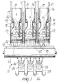
- a furnace for heat treatments of glass sheets is generally designated by the reference numeral 10.
- the furnace 10 comprises a longitudinally-elongated chamber, not shown, which contains roller conveyor means, generally designated by the reference numeral 11, for the glass sheets; only one of said glass sheets is shown in the figures and is designated by the reference numeral 12.
- the furnace 10 comprises irradiation-heating means combined with first and second means for heating by forced convection of air whose temperature is controlled by adjusting its circulation rate; said means are described hereinafter.
- the furnace 10 in fact comprises, above the roller conveyor means 11 and therefore above the glass sheet 12, a combination of the irradiation-heating means and of the first convection-heating means.
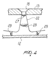
- each radiating panel 13 made of refractory steel which are arranged side by side and longitudinally along the advancement direction of the glass sheets; a heating unit, generally designated by the reference numeral 14, is associated with each radiating panel and is arranged above it; each heating unit is constituted by a radiating electric resistor 15 which has a curved reflecting panel 16 arranged in an upward region.
- the figures also show, for each one of the electric resistors 15, the insulated electrical connections, designated by the reference numeral 17.
- Each one of the radiating panels 13 is provided with holes 18 for the passage of hot air, which strikes the upper surface of the glass sheets 12 being treated when exiting from said holes.
- each one of the holes 18 is shaped so as to have a flared portion 19 directed towards the corresponding heating unit 14.
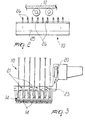
- the hot air that exits from the holes 18 is drawn from inside the chamber of the furnace 10 by fan means, designated by the reference numeral 20, and is then pushed through ducts 21 towards the electric resistors 15 and, once it has struck said resistors, towards the radiating panels 13, from which it exits through the holes 18.
- the reference numeral 22 designates the profiles of the air jets at the exit of the holes 18.
- the particular configuration of the holes 18 allows to give the air particular speed profiles (designated by the reference numerals 27, 28 and 29 in figure 4), which studies conducted by mathematical simulation have shown to be particularly effective for temperature uniformity, particularly in the first heating periods, which are the most critical.
- the speed of the air that exits from the holes 18 can be adjusted by regulating its flow-rate by means of an electronic control of the speed of said fan means 20, which feed said air into a distribution duct 23 connected to the ducts 21.
- the second convection-heating means comprise, below each one of the roller conveyor means 11 and therefore below the glass sheet 12, a plurality of heating elements of the electric-resistor type, designated by the reference numeral 24, which are arranged longitudinally to the advancement direction of said sheets.
- Each one of said heating elements 24 is contained in a corresponding box-like body 25, from which nozzles 26 protrude; said nozzles are meant to distribute, in the region below the glass sheet 12, the hot air drawn by fan means (not shown in the figures) from the chamber of the furnace 10.
- the arrangement of some nozzles is such as to force the air to directly strike the lower surface of the glass sheet 12, whilst other nozzles force the air to directly strike a corresponding roller of the conveyor means 11.
- the temperature of the air that exits from the nozzles 26 is such that by striking both the glass sheet 12 and the rollers of the conveyor means 11 it heats the glass sheet and cools the rollers, significantly contributing to even out the temperatures and the overall heat exchange coefficients, also in relation to those of the upper face of the glass sheet 12.
- the furnace according to the invention by appropriately combining irradiation heating and forced-convection heating with temperature adjustment allowed by adjusting the air circulation rate, controls the balance of the heating conditions on the surfaces of the sheet being treated.
- the furnace according to the invention it is possible to achieve a satisfactory distribution of the temperatures on the glass sheet, substantially eliminating entirely both sheet warping and abrasion of the surfaces of said sheet.
- furnace according to the invention provides these uniformities in a substantially simple and flexible manner.
- the possibility to adjust the temperature by adjusting the air flow rate causes the furnace according to the invention to be adaptable to the treatment of even substantially different glass types.
- the furnace according to the invention substantially completely solves the severe drawbacks caused by the treatment of glass sheets with low-emissivity coatings.
- the materials and the dimensions may be any according to requirements.
Landscapes
- Chemical & Material Sciences (AREA)
- Engineering & Computer Science (AREA)
- Materials Engineering (AREA)
- Organic Chemistry (AREA)
- Tunnel Furnaces (AREA)
- Re-Forming, After-Treatment, Cutting And Transporting Of Glass Products (AREA)
- Laminated Bodies (AREA)
- Electric Stoves And Ranges (AREA)
Abstract
Description
Claims (9)
- A furnace particularly for heat treatments of glass sheets, comprising:characterized in that said irradiation-heating means comprise radiating panels (13), each of which is brought to the preset temperature by an overlying heating unit (14), and is provided with holes (18) for the passage of the hot air that strikes the upper surface of the sheet (12) when exiting, said first means for heating by forced air convection comprising said holes (18) and fan means (2()) for conveying air heated by said heating unit (14) through said holes (18).a longitudinally-elongated chamber which contains roller conveyor means (11) for the glass sheets (12); andirradiation-heating means (13) combined with first (14,18,20,21) and second (24,26) means for heating by forced air convection in which the air temperature is controlled by adjusting its circulation rate, said first and second means being located respectively above and below said conveyor means (11) and therefore above and below the sheets (12) being treated;
- A furnace according to claim 1, characterized in that the air speed is regulated by adjusting its flow-rate through said holes (18) for emission towards the sheets (12) being treated by controlling the speed of said fan means (20) which produce the flow of said air.
- A furnace according to any one or more of the preceding claims, characterized in that each one of said radiating panels (13) is arranged parallel to the longitudinal direction of the conveyor means (11).
- A furnace according to any one or more of the preceding claims, characterized in that each one of the heating units (14) related to said radiating panels (13) is constituted by an electric resistor (15).
- A furnace according to claim 4, characterized in that each one of said heating units (14) is provided with a curved reflector panel (16) arranged above each electric resistor (15).
- A furnace according to any one or more of the preceding claims, characterized in that it comprises ducts (21), provided with said Can means (20), for drawing air from the chamber and for conveying it towards said heating units (14), towards said radiating panels (13) and towards said exit holes (18).
- A furnace according to any one or more of the preceding claims, characterized in that each one of said holes (18) formed in said radiating panels (13) is shaped so as to have a flared portion (19) which is directed towards the corresponding heating unit (14) and determines a preset flow-rate profile (28) of the outgoing air.
- A furnace according to any one or more of the preceding claims, characterized in that said second convection-heating means comprise, below said conveyor means (11) and therefore below the sheets (12) to be treated, a plurality of electrical-resistor heating elements (24) which are arranged parallel to the longitudinal direction of advancement of said sheets (12), each heating element (24) being contained in a box-like body (25) from which nozzles (26) protrude in order to distribute the hot air, which is conveyed into the box-like body and is guided so as to strike, at preset speeds, both the sheets (12) being treated and the rollers of said conveyor means (11).
- A furnace according to claim 8, characterized in that said nozzles (26) are constituted by a plurality of tubes, in which at least one set is directed towards the sheet (12) being treated and at least one set is directed towards a corresponding roller (11).
Applications Claiming Priority (3)
| Application Number | Priority Date | Filing Date | Title |
|---|---|---|---|
| ITPD960176 | 1996-07-05 | ||
| IT96PD000176A IT1287941B1 (en) | 1996-07-05 | 1996-07-05 | OVEN FOR HEAT TREATMENTS OF GLASS SHEETS |
| PCT/EP1997/003407 WO1998001398A1 (en) | 1996-07-05 | 1997-06-30 | Furnace for heat treatments of glass sheets |
Publications (2)
| Publication Number | Publication Date |
|---|---|
| EP0910553A1 EP0910553A1 (en) | 1999-04-28 |
| EP0910553B1 true EP0910553B1 (en) | 2000-08-30 |
Family
ID=11391477
Family Applications (1)
| Application Number | Title | Priority Date | Filing Date |
|---|---|---|---|
| EP97930448A Expired - Lifetime EP0910553B1 (en) | 1996-07-05 | 1997-06-30 | Furnace for heat treatments of glass sheets |
Country Status (8)
| Country | Link |
|---|---|
| US (1) | US6470711B1 (en) |
| EP (1) | EP0910553B1 (en) |
| CN (1) | CN1185174C (en) |
| AT (1) | ATE195924T1 (en) |
| AU (1) | AU3439597A (en) |
| DE (1) | DE69702982T2 (en) |
| IT (1) | IT1287941B1 (en) |
| WO (1) | WO1998001398A1 (en) |
Families Citing this family (30)
| Publication number | Priority date | Publication date | Assignee | Title |
|---|---|---|---|---|
| FI106256B (en) * | 1998-02-18 | 2000-12-29 | Tamglass Ltd Oy | Method and apparatus for directing the heating in a curing oven for glass sheets |
| GB0013022D0 (en) * | 2000-05-31 | 2000-07-19 | Stein Atkinson Strody Ltd | An oven for the heat treatment of glass articles or the like |
| FI110866B (en) | 2000-08-28 | 2003-04-15 | Tamglass Ltd Oy | Method for heating LowE glass sheets in a curing kid |
| GB2369355A (en) * | 2000-11-28 | 2002-05-29 | Efco Ltd | Hot-air circulating means for uniform heating of glass sheet |
| FI20010528A0 (en) | 2001-03-16 | 2001-03-16 | Tamglass Ltd Oy | Method and apparatus for heating glass sheets in a cured oven |
| BE1014065A3 (en) * | 2001-03-23 | 2003-03-04 | Glaverbel | Heating of glass sheets on a roller conveyor in a furnace by radiation and forced convection with the injection of hot gas |
| DE60216739T2 (en) * | 2001-03-23 | 2007-10-04 | Glaverbel | METHOD AND DEVICE FOR HEATING GLASS PANES IN AN OVEN |
| US7290405B2 (en) * | 2001-07-11 | 2007-11-06 | Feracitas Oy | Method and apparatus for conducting heat to a glass sheet |
| FI114631B (en) * | 2001-10-01 | 2004-11-30 | Tamglass Ltd Oy | Method and apparatus for heating glass sheets for curing |
| FI20021015A0 (en) * | 2002-05-30 | 2002-05-30 | Feracitas Oy | Method and apparatus for cooling a glass plate |
| FI20035031A0 (en) * | 2003-03-12 | 2003-03-12 | Tamglass Ltd Oy | Procedure and apparatus for controlling safety glass production and controlling the treatment process |
| DE602004027235D1 (en) * | 2003-03-31 | 2010-07-01 | Glassrobots Oy | REFRIGERATED HEATING OVEN FOR A PREFABLICATED GLASS WASHER |
| US20040237591A1 (en) * | 2003-05-28 | 2004-12-02 | Glasstech, Inc. | Furnace and method using electric resistance and forced convection for heating glass sheets |
| US6783358B1 (en) * | 2003-05-28 | 2004-08-31 | Glasstech, Inc. | Furnace and method for heating coated glass sheets |
| FI120451B (en) * | 2003-06-24 | 2009-10-30 | Uniglass Engineering Oy | Method and apparatus for heating glass |
| DE10330196B4 (en) * | 2003-07-03 | 2009-11-05 | Erdmann, Wolfgang | Plant for the heat treatment of glass |
| US7748237B2 (en) * | 2004-05-27 | 2010-07-06 | Landglass Technology Co. Ltd | Convection glass heating furnace |
| FI115834B (en) * | 2004-06-09 | 2005-07-29 | Tamglass Ltd Oy | Heating glass panels in heating oven involves heating the glass panel from above and below with convection air or with a combination of convection air and radiation heat, where convection air is heated using heat accumulator |
| US20060150683A1 (en) * | 2005-01-11 | 2006-07-13 | Glasstech, Inc. | Apparatus and method for glass sheet quenching |
| US8042359B2 (en) * | 2006-05-18 | 2011-10-25 | Corning Incorporated | Methods and apparatus for heat treating glass sheets |
| US9611029B2 (en) * | 2006-10-11 | 2017-04-04 | The Boeing Company | Floor beam support assembly, system, and associated method |
| EP2125644B1 (en) * | 2006-12-13 | 2012-10-24 | Glassrobots Oy | A convection heating furnace for heating a glass sheet |
| FI126760B (en) * | 2010-01-11 | 2017-05-15 | Glaston Services Ltd Oy | Method and apparatus for supporting glass sheets and heating them with hot gas pad |
| US8826693B2 (en) | 2010-08-30 | 2014-09-09 | Corning Incorporated | Apparatus and method for heat treating a glass substrate |
| WO2014111622A1 (en) * | 2013-01-18 | 2014-07-24 | Feracitas Oy | A method for improving an air circulation and a way for heating air in a glass tempering oven |
| US10526232B2 (en) * | 2013-05-30 | 2020-01-07 | Ppg Industries Ohio, Inc. | Microwave heating glass bending process |
| US11384983B2 (en) * | 2016-10-12 | 2022-07-12 | Tung Chang Machinery And Engineering Co., Ltd. | Glass heating furnace |
| FI128655B (en) | 2019-03-21 | 2020-09-30 | Glaston Finland Oy | Tempering furnace for glass sheets |
| FI129544B (en) * | 2019-07-03 | 2022-04-14 | Glaston Finland Oy | Tempering furnace for glass sheets |
| EP3872040A1 (en) | 2020-02-27 | 2021-09-01 | Feracitas Oy | Effective glass heating process heating convection air into matrix configuratioin |
Family Cites Families (19)
| Publication number | Priority date | Publication date | Assignee | Title |
|---|---|---|---|---|
| NL132487C (en) * | 1962-11-19 | |||
| US3402038A (en) * | 1965-04-02 | 1968-09-17 | Hordis Bros Inc | Apparatus for heating and tempering glass sheets |
| BE788045A (en) * | 1971-11-10 | 1973-02-26 | Bowman E W | METHOD AND APPARATUS FOR RECEIVING GLASSWARE OR ANALOGUE ARTICLES |
| AT362161B (en) | 1979-06-28 | 1981-04-27 | Philips Nv | RECORDING AND / OR PLAYING DEVICE |
| FI62043C (en) | 1980-09-12 | 1982-11-10 | Tamglass Oy | FOERFARANDE OCH ANORDNING FOER ATT FOERHINDRA BOEJNINGEN AV GLSSKIVOR I EN MED VALSAR FOERSEDD UGN I EN HORISONTALHAERD NIGSANORDNING |
| US4336442A (en) | 1981-01-12 | 1982-06-22 | Ppg Industries, Inc. | Combination radiation and convection heater with convection current directing means |
| US4515622A (en) * | 1983-05-09 | 1985-05-07 | Glasstech, Inc. | Glass sheet quench including oppositely angled jets |
| CA1332510C (en) * | 1986-06-02 | 1994-10-18 | Glasstech, Inc. | Gas burner forced convection heating of glass sheets |
| US5176733A (en) | 1988-12-27 | 1993-01-05 | Ford Motor Company | Method and apparatus for directed energy glass heating |
| FR2658499B1 (en) | 1990-02-21 | 1993-05-14 | Saint Gobain Vitrage Int | GLASS SHEET HEATING OVEN. |
| US5154338A (en) * | 1990-06-06 | 1992-10-13 | Senju Metal Industry Co., Ltd. | Solder reflow furnace |
| US5069380A (en) * | 1990-06-13 | 1991-12-03 | Carlos Deambrosio | Inerted IR soldering system |
| DE69308715T2 (en) | 1992-10-15 | 1997-06-19 | Tamglass Eng Oy | Method and furnace for bending glass sheets |
| DE4336364C2 (en) * | 1993-10-25 | 1996-02-29 | Cattin Machines Sa | Device for heating or cooling tabular or band-shaped items to be treated made of glass or ceramic material |
| US5672191A (en) * | 1994-06-20 | 1997-09-30 | Gas Research Institute | Forced convection heating apparatus and process for heating glass sheets therewithin |
| US5814789A (en) * | 1996-07-18 | 1998-09-29 | Btu International, Inc. | Forced convection furnance gas plenum |
| FI101621B (en) * | 1997-04-21 | 1998-07-31 | Tamglass Ltd Oy | Method for heat-soak treatment of cured glass sheets |
| FI106256B (en) * | 1998-02-18 | 2000-12-29 | Tamglass Ltd Oy | Method and apparatus for directing the heating in a curing oven for glass sheets |
| US6050814A (en) * | 1998-12-09 | 2000-04-18 | Glasstech, Inc. | Forced convection furnace for heating glass sheets |
-
1996
- 1996-07-05 IT IT96PD000176A patent/IT1287941B1/en active IP Right Grant
-
1997
- 1997-06-30 EP EP97930448A patent/EP0910553B1/en not_active Expired - Lifetime
- 1997-06-30 WO PCT/EP1997/003407 patent/WO1998001398A1/en not_active Ceased
- 1997-06-30 US US09/214,242 patent/US6470711B1/en not_active Expired - Lifetime
- 1997-06-30 AT AT97930448T patent/ATE195924T1/en active
- 1997-06-30 CN CNB971961557A patent/CN1185174C/en not_active Expired - Lifetime
- 1997-06-30 AU AU34395/97A patent/AU3439597A/en not_active Abandoned
- 1997-06-30 DE DE69702982T patent/DE69702982T2/en not_active Expired - Lifetime
Also Published As
| Publication number | Publication date |
|---|---|
| CN1185174C (en) | 2005-01-19 |
| ITPD960176A1 (en) | 1998-01-05 |
| ATE195924T1 (en) | 2000-09-15 |
| EP0910553A1 (en) | 1999-04-28 |
| AU3439597A (en) | 1998-02-02 |
| DE69702982D1 (en) | 2000-10-05 |
| CN1224406A (en) | 1999-07-28 |
| IT1287941B1 (en) | 1998-08-26 |
| WO1998001398A1 (en) | 1998-01-15 |
| DE69702982T2 (en) | 2001-02-01 |
| US6470711B1 (en) | 2002-10-29 |
Similar Documents
| Publication | Publication Date | Title |
|---|---|---|
| US6470711B1 (en) | Furnace for heat treatments of glass sheets | |
| TWI850351B (en) | Tempering furnace for glass sheets | |
| EP0721922B1 (en) | Method for heating glass sheets to be tempered or heat-strengthened | |
| CN115650567B (en) | Glass tempering heating furnace | |
| TWI437099B (en) | Strip material treatment apparatus | |
| AU715773B2 (en) | Heating glass sheets in tempering furnace | |
| JP3505755B2 (en) | Glass plate heat treatment equipment | |
| US7216511B2 (en) | Furnace apparatus and method for tempering low emissivity glass | |
| EP3994103B1 (en) | Tempering furnace for a glass sheet and a method for heating a glass sheet for tempering | |
| CN100593021C (en) | Convection Furnaces for Tempering Glass Sheets | |
| CN101844862A (en) | Glass toughening furnace based on net array type heating | |
| JP4809633B2 (en) | Method and apparatus for heating glass panels | |
| US3806331A (en) | Glass heating and tempering apparatus | |
| CA2259531C (en) | Furnace for heat treatments of glass sheets | |
| US3223506A (en) | Method and apparatus for vertically supporting and heat treating a glass sheet | |
| US20040083763A1 (en) | Method and device for heating glass sheets in an oven | |
| US5057138A (en) | Method and apparatus for preventing the arching of glass sheets in the roller-equipped furnace of a horizontal tempering plant | |
| JPS62288126A (en) | Glass sheet heating equipment and process | |
| JP3882258B2 (en) | heating furnace | |
| JPS6214009B2 (en) | ||
| GB2369355A (en) | Hot-air circulating means for uniform heating of glass sheet | |
| US2244113A (en) | Lehr and method of treating glassware therein |
Legal Events
| Date | Code | Title | Description |
|---|---|---|---|
| PUAI | Public reference made under article 153(3) epc to a published international application that has entered the european phase |
Free format text: ORIGINAL CODE: 0009012 |
|
| 17P | Request for examination filed |
Effective date: 19990111 |
|
| AK | Designated contracting states |
Kind code of ref document: A1 Designated state(s): AT BE CH DE DK ES FI FR GB IE IT LI SE |
|
| GRAG | Despatch of communication of intention to grant |
Free format text: ORIGINAL CODE: EPIDOS AGRA |
|
| 17Q | First examination report despatched |
Effective date: 19990825 |
|
| GRAG | Despatch of communication of intention to grant |
Free format text: ORIGINAL CODE: EPIDOS AGRA |
|
| GRAG | Despatch of communication of intention to grant |
Free format text: ORIGINAL CODE: EPIDOS AGRA |
|
| GRAH | Despatch of communication of intention to grant a patent |
Free format text: ORIGINAL CODE: EPIDOS IGRA |
|
| GRAH | Despatch of communication of intention to grant a patent |
Free format text: ORIGINAL CODE: EPIDOS IGRA |
|
| GRAA | (expected) grant |
Free format text: ORIGINAL CODE: 0009210 |
|
| AK | Designated contracting states |
Kind code of ref document: B1 Designated state(s): AT BE CH DE DK ES FI FR GB IE IT LI SE |
|
| PG25 | Lapsed in a contracting state [announced via postgrant information from national office to epo] |
Ref country code: ES Free format text: THE PATENT HAS BEEN ANNULLED BY A DECISION OF A NATIONAL AUTHORITY Effective date: 20000830 |
|
| REF | Corresponds to: |
Ref document number: 195924 Country of ref document: AT Date of ref document: 20000915 Kind code of ref document: T |
|
| REG | Reference to a national code |
Ref country code: CH Ref legal event code: EP |
|
| REG | Reference to a national code |
Ref country code: IE Ref legal event code: FG4D |
|
| REF | Corresponds to: |
Ref document number: 69702982 Country of ref document: DE Date of ref document: 20001005 |
|
| ET | Fr: translation filed | ||
| REG | Reference to a national code |
Ref country code: CH Ref legal event code: NV Representative=s name: PATENTANWALTSBUERO EDER AG |
|
| ITF | It: translation for a ep patent filed | ||
| PG25 | Lapsed in a contracting state [announced via postgrant information from national office to epo] |
Ref country code: SE Free format text: LAPSE BECAUSE OF FAILURE TO SUBMIT A TRANSLATION OF THE DESCRIPTION OR TO PAY THE FEE WITHIN THE PRESCRIBED TIME-LIMIT Effective date: 20001130 Ref country code: DK Free format text: LAPSE BECAUSE OF FAILURE TO SUBMIT A TRANSLATION OF THE DESCRIPTION OR TO PAY THE FEE WITHIN THE PRESCRIBED TIME-LIMIT Effective date: 20001130 |
|
| PLBE | No opposition filed within time limit |
Free format text: ORIGINAL CODE: 0009261 |
|
| STAA | Information on the status of an ep patent application or granted ep patent |
Free format text: STATUS: NO OPPOSITION FILED WITHIN TIME LIMIT |
|
| PG25 | Lapsed in a contracting state [announced via postgrant information from national office to epo] |
Ref country code: IE Free format text: LAPSE BECAUSE OF NON-PAYMENT OF DUE FEES Effective date: 20010702 |
|
| 26N | No opposition filed | ||
| REG | Reference to a national code |
Ref country code: GB Ref legal event code: IF02 |
|
| REG | Reference to a national code |
Ref country code: IE Ref legal event code: MM4A |
|
| REG | Reference to a national code |
Ref country code: FR Ref legal event code: PLFP Year of fee payment: 19 |
|
| REG | Reference to a national code |
Ref country code: FR Ref legal event code: PLFP Year of fee payment: 20 |
|
| PGFP | Annual fee paid to national office [announced via postgrant information from national office to epo] |
Ref country code: FI Payment date: 20160630 Year of fee payment: 20 |
|
| PGFP | Annual fee paid to national office [announced via postgrant information from national office to epo] |
Ref country code: AT Payment date: 20160630 Year of fee payment: 20 Ref country code: FR Payment date: 20160628 Year of fee payment: 20 |
|
| PGFP | Annual fee paid to national office [announced via postgrant information from national office to epo] |
Ref country code: GB Payment date: 20160629 Year of fee payment: 20 Ref country code: IT Payment date: 20160629 Year of fee payment: 20 Ref country code: CH Payment date: 20160701 Year of fee payment: 20 Ref country code: DE Payment date: 20160630 Year of fee payment: 20 |
|
| PGFP | Annual fee paid to national office [announced via postgrant information from national office to epo] |
Ref country code: BE Payment date: 20160630 Year of fee payment: 20 |
|
| REG | Reference to a national code |
Ref country code: DE Ref legal event code: R071 Ref document number: 69702982 Country of ref document: DE |
|
| REG | Reference to a national code |
Ref country code: CH Ref legal event code: PL |
|
| REG | Reference to a national code |
Ref country code: GB Ref legal event code: PE20 Expiry date: 20170629 |
|
| PG25 | Lapsed in a contracting state [announced via postgrant information from national office to epo] |
Ref country code: GB Free format text: LAPSE BECAUSE OF EXPIRATION OF PROTECTION Effective date: 20170629 |
|
| REG | Reference to a national code |
Ref country code: AT Ref legal event code: MK07 Ref document number: 195924 Country of ref document: AT Kind code of ref document: T Effective date: 20170630 |