EP0910500B1 - Process and press for manufacturing glued blocks - Google Patents
Process and press for manufacturing glued blocks Download PDFInfo
- Publication number
- EP0910500B1 EP0910500B1 EP97928597A EP97928597A EP0910500B1 EP 0910500 B1 EP0910500 B1 EP 0910500B1 EP 97928597 A EP97928597 A EP 97928597A EP 97928597 A EP97928597 A EP 97928597A EP 0910500 B1 EP0910500 B1 EP 0910500B1
- Authority
- EP
- European Patent Office
- Prior art keywords
- staves
- pressure
- wood
- block
- base sides
- Prior art date
- Legal status (The legal status is an assumption and is not a legal conclusion. Google has not performed a legal analysis and makes no representation as to the accuracy of the status listed.)
- Expired - Lifetime
Links
- 238000000034 method Methods 0.000 title claims abstract description 27
- 238000004519 manufacturing process Methods 0.000 title claims abstract description 5
- 239000002023 wood Substances 0.000 claims abstract description 58
- 239000003292 glue Substances 0.000 claims abstract description 31
- 239000000463 material Substances 0.000 claims description 21
- 238000003825 pressing Methods 0.000 claims description 21
- 238000010438 heat treatment Methods 0.000 claims description 13
- 239000011248 coating agent Substances 0.000 claims description 2
- 238000000576 coating method Methods 0.000 claims description 2
- 239000004033 plastic Substances 0.000 claims description 2
- 230000004913 activation Effects 0.000 claims 1
- 210000001145 finger joint Anatomy 0.000 claims 1
- 239000000853 adhesive Substances 0.000 abstract 1
- 230000001070 adhesive effect Effects 0.000 abstract 1
- 238000004026 adhesive bonding Methods 0.000 description 7
- IHQKEDIOMGYHEB-UHFFFAOYSA-M sodium dimethylarsinate Chemical class [Na+].C[As](C)([O-])=O IHQKEDIOMGYHEB-UHFFFAOYSA-M 0.000 description 5
- 229920000877 Melamine resin Polymers 0.000 description 1
- ISWSIDIOOBJBQZ-UHFFFAOYSA-N Phenol Chemical compound OC1=CC=CC=C1 ISWSIDIOOBJBQZ-UHFFFAOYSA-N 0.000 description 1
- 230000006978 adaptation Effects 0.000 description 1
- 230000015572 biosynthetic process Effects 0.000 description 1
- 239000011093 chipboard Substances 0.000 description 1
- 239000002131 composite material Substances 0.000 description 1
- 239000004020 conductor Substances 0.000 description 1
- 238000010276 construction Methods 0.000 description 1
- 230000008602 contraction Effects 0.000 description 1
- 238000007796 conventional method Methods 0.000 description 1
- 238000005520 cutting process Methods 0.000 description 1
- 238000011161 development Methods 0.000 description 1
- 230000018109 developmental process Effects 0.000 description 1
- 230000003467 diminishing effect Effects 0.000 description 1
- 238000009826 distribution Methods 0.000 description 1
- 238000003780 insertion Methods 0.000 description 1
- 230000037431 insertion Effects 0.000 description 1
- 230000001788 irregular Effects 0.000 description 1
- JDSHMPZPIAZGSV-UHFFFAOYSA-N melamine Chemical compound NC1=NC(N)=NC(N)=N1 JDSHMPZPIAZGSV-UHFFFAOYSA-N 0.000 description 1
- 238000012986 modification Methods 0.000 description 1
- 230000004048 modification Effects 0.000 description 1
Images




Classifications
-
- B—PERFORMING OPERATIONS; TRANSPORTING
- B27—WORKING OR PRESERVING WOOD OR SIMILAR MATERIAL; NAILING OR STAPLING MACHINES IN GENERAL
- B27M—WORKING OF WOOD NOT PROVIDED FOR IN SUBCLASSES B27B - B27L; MANUFACTURE OF SPECIFIC WOODEN ARTICLES
- B27M3/00—Manufacture or reconditioning of specific semi-finished or finished articles
- B27M3/0013—Manufacture or reconditioning of specific semi-finished or finished articles of composite or compound articles
- B27M3/0026—Manufacture or reconditioning of specific semi-finished or finished articles of composite or compound articles characterised by oblong elements connected laterally
- B27M3/0053—Manufacture or reconditioning of specific semi-finished or finished articles of composite or compound articles characterised by oblong elements connected laterally using glue
-
- B—PERFORMING OPERATIONS; TRANSPORTING
- B30—PRESSES
- B30B—PRESSES IN GENERAL
- B30B7/00—Presses characterised by a particular arrangement of the pressing members
- B30B7/04—Presses characterised by a particular arrangement of the pressing members wherein pressing is effected in different directions simultaneously or in turn
-
- Y—GENERAL TAGGING OF NEW TECHNOLOGICAL DEVELOPMENTS; GENERAL TAGGING OF CROSS-SECTIONAL TECHNOLOGIES SPANNING OVER SEVERAL SECTIONS OF THE IPC; TECHNICAL SUBJECTS COVERED BY FORMER USPC CROSS-REFERENCE ART COLLECTIONS [XRACs] AND DIGESTS
- Y10—TECHNICAL SUBJECTS COVERED BY FORMER USPC
- Y10T—TECHNICAL SUBJECTS COVERED BY FORMER US CLASSIFICATION
- Y10T156/00—Adhesive bonding and miscellaneous chemical manufacture
- Y10T156/10—Methods of surface bonding and/or assembly therefor
- Y10T156/1052—Methods of surface bonding and/or assembly therefor with cutting, punching, tearing or severing
- Y10T156/1062—Prior to assembly
- Y10T156/1066—Cutting to shape joining edge surfaces only
-
- Y—GENERAL TAGGING OF NEW TECHNOLOGICAL DEVELOPMENTS; GENERAL TAGGING OF CROSS-SECTIONAL TECHNOLOGIES SPANNING OVER SEVERAL SECTIONS OF THE IPC; TECHNICAL SUBJECTS COVERED BY FORMER USPC CROSS-REFERENCE ART COLLECTIONS [XRACs] AND DIGESTS
- Y10—TECHNICAL SUBJECTS COVERED BY FORMER USPC
- Y10T—TECHNICAL SUBJECTS COVERED BY FORMER US CLASSIFICATION
- Y10T156/00—Adhesive bonding and miscellaneous chemical manufacture
- Y10T156/10—Methods of surface bonding and/or assembly therefor
- Y10T156/1052—Methods of surface bonding and/or assembly therefor with cutting, punching, tearing or severing
- Y10T156/1062—Prior to assembly
- Y10T156/1067—Continuous longitudinal slitting
-
- Y—GENERAL TAGGING OF NEW TECHNOLOGICAL DEVELOPMENTS; GENERAL TAGGING OF CROSS-SECTIONAL TECHNOLOGIES SPANNING OVER SEVERAL SECTIONS OF THE IPC; TECHNICAL SUBJECTS COVERED BY FORMER USPC CROSS-REFERENCE ART COLLECTIONS [XRACs] AND DIGESTS
- Y10—TECHNICAL SUBJECTS COVERED BY FORMER USPC
- Y10T—TECHNICAL SUBJECTS COVERED BY FORMER US CLASSIFICATION
- Y10T156/00—Adhesive bonding and miscellaneous chemical manufacture
- Y10T156/10—Methods of surface bonding and/or assembly therefor
- Y10T156/1052—Methods of surface bonding and/or assembly therefor with cutting, punching, tearing or severing
- Y10T156/1062—Prior to assembly
- Y10T156/1075—Prior to assembly of plural laminae from single stock and assembling to each other or to additional lamina
-
- Y—GENERAL TAGGING OF NEW TECHNOLOGICAL DEVELOPMENTS; GENERAL TAGGING OF CROSS-SECTIONAL TECHNOLOGIES SPANNING OVER SEVERAL SECTIONS OF THE IPC; TECHNICAL SUBJECTS COVERED BY FORMER USPC CROSS-REFERENCE ART COLLECTIONS [XRACs] AND DIGESTS
- Y10—TECHNICAL SUBJECTS COVERED BY FORMER USPC
- Y10T—TECHNICAL SUBJECTS COVERED BY FORMER US CLASSIFICATION
- Y10T156/00—Adhesive bonding and miscellaneous chemical manufacture
- Y10T156/12—Surface bonding means and/or assembly means with cutting, punching, piercing, severing or tearing
- Y10T156/13—Severing followed by associating with part from same source
-
- Y—GENERAL TAGGING OF NEW TECHNOLOGICAL DEVELOPMENTS; GENERAL TAGGING OF CROSS-SECTIONAL TECHNOLOGIES SPANNING OVER SEVERAL SECTIONS OF THE IPC; TECHNICAL SUBJECTS COVERED BY FORMER USPC CROSS-REFERENCE ART COLLECTIONS [XRACs] AND DIGESTS
- Y10—TECHNICAL SUBJECTS COVERED BY FORMER USPC
- Y10T—TECHNICAL SUBJECTS COVERED BY FORMER US CLASSIFICATION
- Y10T156/00—Adhesive bonding and miscellaneous chemical manufacture
- Y10T156/17—Surface bonding means and/or assemblymeans with work feeding or handling means
- Y10T156/1702—For plural parts or plural areas of single part
- Y10T156/1744—Means bringing discrete articles into assembled relationship
- Y10T156/1751—At least three articles
Definitions
- the present invention relates to a process of the type which is stated in the preamble of claim 1, and a device for performing the process.
- WO 83/03791 describes a method and arrangement for making glue joint blocks according to the priorly known technics (see especially pages 11 and 12).
- the triangular staves of wood are provided on place between the lateral pressure plates which then are place having a distance between them adapted to the pattern of triangular staves which are layed on a lower board.
- the staves having their bases uppwards are pressed down a little such that their tops are protruding downwards between the bases or the staves having their bases downwards and then fixed in that position.
- the pressure proceeding begins by pressing the lateral pressure plates together.
- the pressure is here provided against the outer staves in the block.
- One object of the process and device according to the invention is to achieve durable glue joints between essentially triangular staves of wood which are laid beside each other.
- Another object of the process and device according to the invention is to achieve a glue joint between staves of wood laid beside each other which is satisfactory all the way through to the surface of the block formed from them.
- Fig. 1 triangular staves of wood are shown laid out side by side alternatively with the base facing downwards and alternatively with the base facing upwards and are seen from one end.
- the outermost staves of wood 1 and 2 are essentially right-angled between the base and the outer side.
- the other staves of wood 3 - 8 are preferably isosceles, or, even better, equilateral. It is also possible within the scope of the invention to conceive using irregular triangular cross-sections but it is not directly practical to use such.
- Fig. 1 shows that it is known in the prior art during gluing to press against the outermost staves of wood 1 and 2 via press blocks 1' and 2', respectively, i.e. from the longitudinal edge sides.
- the glue joints are achieved through the triangular staves of wood being pressed together from the broad sides.
- a press head 9 and 10 is placed on each of the broad sides in order to hold the staves of wood well pressed together during the formation of the glue joints.
- An adjustable dolly 11 and 12 is placed by each of the outermost staves of wood in order to hold together the staves of wood in the lateral direction.
- it can also be suitable to provide a certain pressure against the staves of wood from the dollies so that the staves of wood are well held together in the lateral direction during the whole press operation.
- a variant is to pump with pressure during the pressing together phase. This evens out the pressure force between the joints.
- the wood material with a triangular-shaped cross-section is preferably laid into the press with the annual rings directed essentially in line with each other so that the material/block receives a similar expansion/contraction at different moisture levels and therefore gives a material which, relatively seen, warps less than if the annual rings were laid out in another way.
- they should be directed essentially transverse to the width of the block, as is shown in Fig. 2A and 2B. In this way the movements due to moisture takes place essentially in the direction of thickness of the finished block and not along its width, which is an important advantage if the block is used, for example, as a floor covering or the like.
- a sawing device can saw the completed glued block into thin sheets through cutting essentially parallel with the broad sides of the block.
- Fig. 2A shows essentially isosceles pieces of wood.
- Fig. 2B shows that also gluing together of pieces of wood with a triangular cross-section with a right angle, e.g. the angles 45°/45°/90°, can function with the method according to the invention.
- Such triangular pieces of wood can be produced by the well-known sawing pattern called quarter-sawing.
- Dollies 11 and 12 determine the width of the block in the lateral direction, and the pressure from the press on the extended surfaces causes the inclined surfaces to glide towards each other so that the transverse surfaces are pressed towards each other, by means of which a good glue joint is also achieved there.
- the essentially triangular-shaped wood elements - in order to give a satisfactory glue joint - should be displaced so that a certain part of the peak lies above the surface of the base of the surrounding triangles in order to ensure that the glue joint extends all the way up to the finished surface without faults.
- narrow stripes are formed in the surface, which enhance the appearance of the surface.
- the risk that the point comes under the base surface is large, as is illustrated at the joint between the staves of wood 3, 4 and 5 in Fig. 1, when the pressure of the press in the glue joint diminishes drastically and the glue joint becomes poor.
- the block must be planed down in order to have an acceptable appearance.
- Fig. 3 shows an embodiment in which the press heads 13 and 14 are provided with parts 15 and 16, respectively, which have spaces 17 and 18, respectively, between them which can accommodate projecting peak edges of the staves of wood.
- the press plates of the press can alternatively be equipped with a flat surface with longitudinal grooves where the peak edges from the triangular-shaped material can fit in. It should, however, be observed that it is not necessary that the triangular staves of wood have completely pointed edges in the part which is directed towards a block surface. During planing it is practical, most of all for the sake of feed devices, to plane down one point of the triangular profile. This type of planed staves of wood can perfectly well be used in accordance with the invention.
- the press plates have a relatively thick coating of a material which is yielding to counterpressure from a projecting part, such as a pointed edge, from the essentially flat glue joint plate but which is essentially non-yielding in general (not shown).
- a suitable material is therefore rubber or elastic or rigid soft plastic where the pointed edges during pressing are introduced into the material.
- the material should be relatively stiff in order to be essentially less yielding to the broad sides of the triangular staves of wood than to their pointed edges.
- the material should have a low friction to the introduction of the pointed edges and preferably also in the transverse direction at the joint between the material and the wood elements.
- the press has an adjustable compartment, comprising e.g. adjustable side pieces 19 and 20, respectively, for the insertion of the triangular staves of wood lying beside each other.
- the side pieces should be made in such a way that the compartment corresponds to the expected width of the produced block with suitable tolerances.
- each plate in the upper part of the press can be equipped with a vertical force producer, e.g. hydraulically, which presses together the material which is provided with glue during the adaptation.
- a vertical force producer e.g. hydraulically, which presses together the material which is provided with glue during the adaptation.
- a vertical force is obtained which gives an even pressure on each piece of material (stave) independent of the width of the block, which gives good glue joints over the whole surface.
- the pressure heads 13 and 14 are placed between an upper part 21 and a lower part 22.
- Hydraulic traction cylinders 23 and 25 are placed on both sides and one of them is controlled during the opening of the press and the other during the pressing operation. Despite only two being shown, there should be at least four, i.e. two on each side of the pressure-loaded region.
- the pressure cylinder 23 is pivotally fastened at both ends to the upper part 21 and to the lower part 22. Beside and inside the pressure cylinder 23, a pull rod 24 is pivotally fastened in the same way.
- the pressure head 14 can be, but does not have to be, comprised as a part of the lower part 22.
- Fig. 3 shows that the hydraulic cylinder 25 is rotatably mounted on the lower part 22 and equipped with a hook 26 for hooking onto a peg 27 on the upper part 21.
- the upper part 21 is openable at one end and rotatable around the pull rod 24 by being pulled by means of the hydraulic cylinder 23 for easy placement of the triangular staves of wood and regulation of the side pieces 19 and 20.
- Pressing together occurs by means of the hydraulic cylinder 25 when it is hooked fast in the upper part 21.
- the hydraulic cylinder 23 is in this case inactive.
- Two pressing blocks 28 and 29 are arranged over the pressing plate, which each are anchored to the pressing plate via at least two links 30, 3 land 32, 33, respectively, which are somewhat movable transversely and which run in the same direction as the direction of grain of the triangular staves of wood.
- the pressing blocks 28 and 29 are pivotally fastened to a block 34, which is pivotally fastened to the upper part 34.
- the pressure units are formed on the base sides of the glued block by means of a number of loose and/or guidable flat plates on a foundation 37 and 38, respectively, upon which the pressure is applied in a way as described in connection to Fig. 3.
- the plates 39 and 40, respectively, placed on the foundation 37 and 38 are movable in the transverse direction, e.g. along guides (not shown), in order to give a space between them for each point edge of the triangular board and are controllably adjustable for the various conceivable dimensions of the material.
- the adjustment of the plates 39 and 40 can possibly take place by hand but also with the help of electronic control systems and performed during the unloaded condition of the press, i.e. before the hydraulic cylinder 25 in the locked position is activated.
- the side supports are normally controllably adapted to fit the desired finish dimension and chosen material dimension.
- the block can also be manufactured in a continuously working press which is a modification of that described in connection to Fig. 4A.
- This press can have plates 39 and 40 with a significantly smaller length than the length of the staves of wood in their direction of grain.
- the side pieces 19 of the press can even be displaceable for movement in the longitudinal direction along the block.
- the staves of wood of the block are placed stationary, possibly through their ends being firmly anchored (not shown).
- the moving parts of the press can thereby during movement run against e.g. ball races, which give low friction in the longitudinal direction and high stiffness in the pressure direction.
- the movable parts can then be returned to their original position by means of, for example, a return transport or hinged arms so that a flat, continuous (and, in the longitudinal direction. easily movable) pressure is given to the material.
- a return transport or hinged arms so that a flat, continuous (and, in the longitudinal direction. easily movable) pressure is given to the material.
- FIG. 4B shows schematically such an embodiment in a longitudinal section of part of the upper part of the press, where the plates 39 are shaped as links and a ball race 45 is situated between the pressure plate 37 and the plates 39.
- the pressure plate 37 is moved stepwise in the direction of arrow A along the stave of wood 46, while at the same time the joined-together plates 39 step by step are moved downwards towards the staves of wood by the pressure plate 37.
- the pressure plates can instead be equipped with heating elements or be heated by means of IR-technique on the outside in order for the glue in the glued block to set quickly and surely during the pressing operation.
- a glue should be chosen which does not set quickly before it has been subjected to heat, so that the gluing together does not take place outside the portion of the glued block which has been subjected to pressure.
- a suitable glue in this connection is phenol/rescorcinol glue or melamine glue for weather-resistant products or PVAC-glue for indoor products.
- microwave energy or HF-heating can be provided for setting the glue.
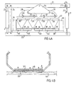
- An embodiment of a press with these features is shown in Fig. 5.
- the staves of wood which are to form the glued block 50 are placed on the base plate 51 between the side pieces 52 and 53.
- An adjusting means 54 for these is indicated schematically.
- the upper part 55 of the press in this embodiment is guided to press against the glued block 50 by hydraulic cylinders 58 and 59 arranged beside each other, and comprises a high-frequency heating part 56 supplied from a high-frequency source HF.
- the heating part is of known type and consequently does not need to be described more closely.
- the plates 57 facing towards the glued block can in this connection be provided with openings, which in the main are greater than the wavelength of the supplied energy, or the plates can be made of a non-conducting material with a suitably low ⁇ , e.g. a suitable composite, which the supplied energy can pass through, whereby the setting can take place more quickly with a higher productivity as a consequence.
- a suitable glue in this embodiment is e.g. PVAC-glue.
- the triangular staves of wood are laid after each other in the press, either end to end with the adjacent staves of wood in the transverse direction displaced in relation to each other for the sake of strength, or with each end (and/or at least one of the long sides) of the staves of wood prepared for splicing (finger splices) which gives a higher total strength.
- each stave can be obliquely cut even at its ends before the stave is laid together with another obliquely sawed stave at its end to make an extended stave.
- the individual staves in a block could be extended at different lengths as illustrated at the end cuts 61, 62 and 63. In this way, endless blocks could be created which could be cut in arbitrary lengths.
- the oblique end cuts could be smooth as at 61 and 62 or spliced as at 63, where the finger cut is visible from the surface of the block, or as at 64 showing an end cut having the slicing parallel to the surface of the block such that only a straight line is apparent from the block surface.
- a particular oblique cut of this kind is shown at 65 in FIG 6B in that the cut is smooth at the ends and in the middle in order not to influence the surface parts and in order to make it possible to divide the block into two and still having a nice surface at the cut.
- the finger cut could also be perpendicular to the block surface as illustrated at 66.
Landscapes
- Engineering & Computer Science (AREA)
- Life Sciences & Earth Sciences (AREA)
- Manufacturing & Machinery (AREA)
- Wood Science & Technology (AREA)
- Forests & Forestry (AREA)
- Mechanical Engineering (AREA)
- Lining Or Joining Of Plastics Or The Like (AREA)
- Devices For Post-Treatments, Processing, Supply, Discharge, And Other Processes (AREA)
- Road Paving Structures (AREA)
- Buffer Packaging (AREA)
Abstract
Description
- Fig. 1
- shows an end view of a block and illustrates schematically the correct and incorrect placing of triangular staves of wood during gluing together,
- Figs. 2A & 2B
- show sections through a first embodiment of a device for pressing together staves of wood during gluing, and also illustrate a suitable orientation of the annual rings of the staves of wood which are to be glued together,
- Fig. 3
- shows a section through a schematically illustrated second embodiment of a device for pressing together staves of wood during gluing,
- Fig. 4A
- shows an end view through a schematically illustrated third embodiment of a device for pressing together staves of wood during gluing,
- Fig. 4B
- shows a schematic longitudinal section through a part of the device shown in Fig. 4A, and
- Fig. 5
- shows an embodiment with HF-heating of the glued block during pressing.
- FIG. 6A and 6B
- shows a perspective view, partly in section, and a longitudinal section along the broken line VI - VI in FIG 6A, respectively, of joints in the logitudinal direction.
Claims (21)
- Process for the manufacturing of a glued block of triangular cross-section, elongated staves (3-8) of wood where the staves for forming a block are laid beside each other with alternate staves (4) with their base sides downwards and alternate ones (3) with their base sides upwards and glue applied between adjacent surfaces between the staves, wherein the main pressure force to glue the staves firmly together is exerted transverse to the base sides of the staves (3-8), which is obtained by a movement of a common pressure plate (10, 13, 37) in the said direction while the staves are locked between two lateral stops.
- Process according to Claim 1, characterized by providing cavities in the pressure plate and/or a support plate in front of the point edges of the triangular staves of wood or providing a material for the pressure plate flexible when actuated by point edges in order to provide pressure force with considerably higher force onto the base sides of the triangular staves than on their opposite peak edges.
- Process according to Claim 1 or 2, characterized in that side supports (11,12;19, 20) are positioned against the longitudinal edges before the pressure force is exerted on the base sides.
- Process according to Claim 3, characterized in that the side supports are rigidly set.
- Process according to Claim 3, characterized in that the side supports are controllably adjusted.
- Process according to Claim 3, characterized in that a pressure force is also exerted on the side supports in a direction towards the glued block.
- Process according to any of the previous claims, characterized in that the glued block is heated up during pressing towards the base sides of the staves, at least in the pressing region.
- Process according to Claim 7, characterized in that the heating takes place through heating of the pressure tool.
- Process according to Claim 7, characterized in that the heating takes place through microwave- or HF-heating of the glued plate.
- Process according to anyone of the preceding Claims, characterized in that each stave is obliquely cut at its end and joined with another stave also cut obliquely at its end to provide an extended stave, in that several staves could be extended in this way, and in that several extended staves are laid beside each other.
- Process according to anyone of the Claims 1 to 9, characterized in that each stave is obliquely or transverse cut using finger joint technique at its end and joined with another stave also cut accordingly at its end to provide an extended stave, in that several staves could be extended in this way, and in that several extended staves are laid beside each other.
- Press arrangement for manufacturing of a glued block made of triangular cross-section staves of wood, where the staves are laid beside each other with alternate staves with their base sides downwards and alternate ones with their base sides upwards and glue applied between adjacent surfaces between the staves, a pressure plate (10;13,15;37,39) is provided facing towards the upwardly facing base sides of the staves, and a supporting plate (9;14,16; 38, 40), for supporting the down-wardly facing base sides of the staves, characterized byside supports placed along each long side edge of the laid out staves to lock the staves between lateral stops, anda pressure supplying device (21-25,28,29,34) moving the pressure plate towards the bases of the triangles of the slaves in the direction towards the support plate during activation.
- Press device according to Claim 12, characterized in that the side supports (11,12;19,20) are placed at a mutual distance which is adapted to the desired transverse dimension of the block.
- Press device according to Claim 12 or 13, characterized in that the support plate and/or the pressure plate have cavities directly in front of the point edges of the triangular staves of wood.
- Press device according to Claim 12 or 13, characterized in that the support plate and/or the pressure plate have a coating of a material (e.g. rubber or plastic), which is yielding to pressing from a point edge of the staves which extend out between two adjacent base sides but which is otherwise essentially non-yielding.
- Press device according to Claim 12, 13 or 14, characterized in that the support plate and/or the pressure plate comprise laterally adjustable plate sections (40, 39).
- Press device according to any of Claims 12 - 16, characterized by a heating arrangement for heating the staves during applied pressure.
- Press device according to Claim 17, characterized in that the heating arrange-ment is a microwave- or HF-heating device.
- Press device according to any of Claims 12 - 18 for continuous pressing of glued blocks, characterized in that its press region extends over a part of the length of the glued block and is movable in order to displace the pressure zone along the plate at suitable time intervals adapted to the setting time of the glue used.
- Press device according to any of Claims 12 - 19. characterized in that the triangular staves of wood are laid with the annual rings orientated essentially transverse to the opposite block surfaces.
- Press device according to any of Claims 12 - 20, characterized in that, when laid in the press device, each stave is obliquely cut at its end and joined with another stave also cut obliquely at its end to provide an extended stave, several staves could be extended in this way, and several extended staves are laid beside each other, the pressure plates are provided also across the joints between the extended staves..
Applications Claiming Priority (3)
| Application Number | Priority Date | Filing Date | Title |
|---|---|---|---|
| SE9602426 | 1996-06-19 | ||
| SE9602426A SE9602426L (en) | 1996-06-19 | 1996-06-19 | Procedure and pressure for the manufacture of glue joint |
| PCT/SE1997/001070 WO1997048534A1 (en) | 1996-06-19 | 1997-06-17 | Process and press for manufacturing glued blocks |
Publications (2)
| Publication Number | Publication Date |
|---|---|
| EP0910500A1 EP0910500A1 (en) | 1999-04-28 |
| EP0910500B1 true EP0910500B1 (en) | 2000-03-01 |
Family
ID=20403077
Family Applications (1)
| Application Number | Title | Priority Date | Filing Date |
|---|---|---|---|
| EP97928597A Expired - Lifetime EP0910500B1 (en) | 1996-06-19 | 1997-06-17 | Process and press for manufacturing glued blocks |
Country Status (10)
| Country | Link |
|---|---|
| US (1) | US6315860B1 (en) |
| EP (1) | EP0910500B1 (en) |
| JP (1) | JP2000512579A (en) |
| AT (1) | ATE189987T1 (en) |
| AU (1) | AU721239B2 (en) |
| CA (1) | CA2256521A1 (en) |
| DE (1) | DE69701362T2 (en) |
| NZ (1) | NZ332828A (en) |
| SE (1) | SE9602426L (en) |
| WO (1) | WO1997048534A1 (en) |
Families Citing this family (14)
| Publication number | Priority date | Publication date | Assignee | Title |
|---|---|---|---|---|
| US6460868B2 (en) * | 1999-10-19 | 2002-10-08 | Jeffrey Madrid | Corrugated skateboard deck and method of corrugating skateboard decks |
| SE523108C3 (en) * | 2001-08-09 | 2004-04-14 | Stefan Hellberg | Panel for surface covering |
| US20050000185A1 (en) * | 2003-07-01 | 2005-01-06 | Edgar Russell A. | Equilateral strand composite lumber and method of making same |
| DE102004059816A1 (en) * | 2004-12-07 | 2006-06-08 | GreCon Dimter Holzoptimierung Süd GmbH & Co. KG | Gluing press for manufacturing of plate, has stopper for woods which can be glue-pressed and motorizably movable in direction of press unit by spindle drives that are drive-connected with hydraulic motor |
| DE502006001072D1 (en) * | 2006-05-03 | 2008-08-21 | Ligmatech Automationssysteme | Case Press |
| FI20070224A7 (en) * | 2007-03-19 | 2008-09-20 | Stora Enso Timber Oy Ltd | Glued wood product and method for manufacturing a glued wood product |
| CH703019B1 (en) * | 2010-05-10 | 2012-05-31 | Alstom Hydro France | Press module for impregnated conductor bars large electrical machines and thus equipped pressing device. |
| SE538283C2 (en) | 2014-08-08 | 2016-04-26 | Stora Enso Oyj | A gluelam structural member and a method of producing such agluelam structural member |
| TWI556931B (en) * | 2015-01-30 | 2016-11-11 | Wire joint tenon forming machine | |
| TWI556930B (en) * | 2015-01-30 | 2016-11-11 | Wooden tenon crimping machine | |
| DE102016003506A1 (en) * | 2016-03-18 | 2017-09-21 | Weinig Dimter Gmbh & Co. Kg | Process for the production of blocks of juxtaposed, glued together wooden parts and plant for carrying out the method |
| DE102023111446B3 (en) | 2023-05-03 | 2024-04-25 | Minda Industrieanlagen Gmbh | Method for producing a rectangular wooden panel from individual boards |
| CN118099248B (en) * | 2024-04-26 | 2024-07-23 | 正泰新能科技股份有限公司 | A photovoltaic cell film coating press |
| FR3163596A1 (en) * | 2024-06-25 | 2025-12-26 | Groupe Briand | Press for clamping glued wooden blades for the simultaneous production of two longitudinal glued laminated timber elements |
Family Cites Families (10)
| Publication number | Priority date | Publication date | Assignee | Title |
|---|---|---|---|---|
| US2198245A (en) * | 1937-08-02 | 1940-04-23 | Oliver P M Goss | Method of manufacturing lumber |
| US3961654A (en) * | 1973-02-20 | 1976-06-08 | Earl Dean Hasenwinkle | Log cutting and rejoining process |
| GB1603845A (en) | 1977-08-24 | 1981-12-02 | British Industrial Plastics | Compression moulding machines |
| US4122878A (en) * | 1977-12-14 | 1978-10-31 | Baltek Corporation | Technique for converting balsa logs into panels |
| NZ193046A (en) | 1980-03-05 | 1984-04-27 | Toledo Engineering Co Ltd | Finger-jointing press |
| DE3216669A1 (en) * | 1982-05-04 | 1983-11-10 | Peter 2057 Reinbek Polaczek | METHOD FOR PROCESSING ROUND WOOD TO CONSTRUCTION WOOD OR VENEER AND DEVICE FOR CARRYING OUT THE METHOD |
| US4547255A (en) * | 1984-10-09 | 1985-10-15 | Modern Globe, Inc. | Press construction |
| SE505056C2 (en) * | 1991-03-19 | 1997-06-16 | Martin Wiklund | Procedure for decomposing logs |
| SE501131C2 (en) * | 1992-11-04 | 1994-11-21 | Martin Wiklund | Methods of making disc shaped elements of end wood type, as well as plate and elements made therewith |
| JPH0732325A (en) * | 1993-07-12 | 1995-02-03 | Ibiden Co Ltd | Laminated wood and its manufacture |
-
1996
- 1996-06-19 SE SE9602426A patent/SE9602426L/en unknown
-
1997
- 1997-06-17 DE DE69701362T patent/DE69701362T2/en not_active Expired - Fee Related
- 1997-06-17 NZ NZ332828A patent/NZ332828A/en not_active IP Right Cessation
- 1997-06-17 EP EP97928597A patent/EP0910500B1/en not_active Expired - Lifetime
- 1997-06-17 WO PCT/SE1997/001070 patent/WO1997048534A1/en not_active Ceased
- 1997-06-17 AU AU32815/97A patent/AU721239B2/en not_active Ceased
- 1997-06-17 US US09/202,224 patent/US6315860B1/en not_active Expired - Fee Related
- 1997-06-17 JP JP10502802A patent/JP2000512579A/en not_active Ceased
- 1997-06-17 CA CA002256521A patent/CA2256521A1/en not_active Abandoned
- 1997-06-17 AT AT97928597T patent/ATE189987T1/en not_active IP Right Cessation
Also Published As
| Publication number | Publication date |
|---|---|
| EP0910500A1 (en) | 1999-04-28 |
| SE9602426D0 (en) | 1996-06-19 |
| JP2000512579A (en) | 2000-09-26 |
| DE69701362D1 (en) | 2000-04-06 |
| NZ332828A (en) | 2000-08-25 |
| WO1997048534A1 (en) | 1997-12-24 |
| ATE189987T1 (en) | 2000-03-15 |
| AU3281597A (en) | 1998-01-07 |
| US6315860B1 (en) | 2001-11-13 |
| CA2256521A1 (en) | 1997-12-24 |
| SE9602426L (en) | 1997-12-20 |
| DE69701362T2 (en) | 2000-07-06 |
| AU721239B2 (en) | 2000-06-29 |
Similar Documents
| Publication | Publication Date | Title |
|---|---|---|
| AU721239B2 (en) | Process and press for manufacturing glued blocks | |
| US6779576B2 (en) | Wood-gluing and clamping system | |
| EP1688228B1 (en) | Process for the manufacture of a veneer | |
| EP2422027B1 (en) | Floor panel | |
| US7678425B2 (en) | Process for finishing a wooden board and wooden board produced by the process | |
| US4731140A (en) | Wooden tile and a method of making the same | |
| US6162312A (en) | Method of making a resin impregnated composite wood product from waste, scrap, and used wood | |
| NO339429B1 (en) | Particleboard and method of making it | |
| US6214148B1 (en) | System for applying a wood veneer across a corner of an elongate core | |
| Shi et al. | Wood-based composites: plywood and veneer-based products | |
| FI102055B (en) | Process for producing a disc shaped element of end tree type, so-called iv shaped element and plate | |
| US20120282423A1 (en) | Joined Veneer Strip | |
| CN1008076B (en) | Rolling up the sheet into a material | |
| US4311177A (en) | Process for repairing a damaged section of a bowling lane | |
| EP0074821A2 (en) | Method of making a wooden tile | |
| JP2002326205A (en) | Color grain board having artificial grain and natural grain | |
| WO2000069606A1 (en) | Method and device for compressing wood | |
| AU2002344891A1 (en) | Wood-gluing and clamping system and products |
Legal Events
| Date | Code | Title | Description |
|---|---|---|---|
| PUAI | Public reference made under article 153(3) epc to a published international application that has entered the european phase |
Free format text: ORIGINAL CODE: 0009012 |
|
| 17P | Request for examination filed |
Effective date: 19981207 |
|
| AK | Designated contracting states |
Kind code of ref document: A1 Designated state(s): AT BE CH DE DK ES FI FR GB GR IE IT LI LU MC NL PT SE |
|
| GRAG | Despatch of communication of intention to grant |
Free format text: ORIGINAL CODE: EPIDOS AGRA |
|
| 17Q | First examination report despatched |
Effective date: 19990520 |
|
| GRAG | Despatch of communication of intention to grant |
Free format text: ORIGINAL CODE: EPIDOS AGRA |
|
| GRAH | Despatch of communication of intention to grant a patent |
Free format text: ORIGINAL CODE: EPIDOS IGRA |
|
| GRAH | Despatch of communication of intention to grant a patent |
Free format text: ORIGINAL CODE: EPIDOS IGRA |
|
| GRAA | (expected) grant |
Free format text: ORIGINAL CODE: 0009210 |
|
| AK | Designated contracting states |
Kind code of ref document: B1 Designated state(s): AT BE CH DE DK ES FI FR GB GR IE IT LI LU MC NL PT SE |
|
| PG25 | Lapsed in a contracting state [announced via postgrant information from national office to epo] |
Ref country code: NL Free format text: LAPSE BECAUSE OF FAILURE TO SUBMIT A TRANSLATION OF THE DESCRIPTION OR TO PAY THE FEE WITHIN THE PRESCRIBED TIME-LIMIT Effective date: 20000301 Ref country code: GR Free format text: LAPSE BECAUSE OF NON-PAYMENT OF DUE FEES Effective date: 20000301 Ref country code: FR Free format text: LAPSE BECAUSE OF FAILURE TO SUBMIT A TRANSLATION OF THE DESCRIPTION OR TO PAY THE FEE WITHIN THE PRESCRIBED TIME-LIMIT Effective date: 20000301 Ref country code: ES Free format text: THE PATENT HAS BEEN ANNULLED BY A DECISION OF A NATIONAL AUTHORITY Effective date: 20000301 Ref country code: BE Free format text: LAPSE BECAUSE OF FAILURE TO SUBMIT A TRANSLATION OF THE DESCRIPTION OR TO PAY THE FEE WITHIN THE PRESCRIBED TIME-LIMIT Effective date: 20000301 |
|
| REF | Corresponds to: |
Ref document number: 189987 Country of ref document: AT Date of ref document: 20000315 Kind code of ref document: T |
|
| RIN1 | Information on inventor provided before grant (corrected) |
Inventor name: WIKLUND, RUDOLF Inventor name: WIKLUND, MARTIN Inventor name: WIKLUND, KJELL Inventor name: SANDBERG, DICK Inventor name: LUNDQVIST, AKE Inventor name: HOLMBERG, HANS |
|
| REG | Reference to a national code |
Ref country code: CH Ref legal event code: EP |
|
| REF | Corresponds to: |
Ref document number: 69701362 Country of ref document: DE Date of ref document: 20000406 |
|
| ITF | It: translation for a ep patent filed | ||
| REG | Reference to a national code |
Ref country code: IE Ref legal event code: FG4D |
|
| PG25 | Lapsed in a contracting state [announced via postgrant information from national office to epo] |
Ref country code: PT Free format text: LAPSE BECAUSE OF FAILURE TO SUBMIT A TRANSLATION OF THE DESCRIPTION OR TO PAY THE FEE WITHIN THE PRESCRIBED TIME-LIMIT Effective date: 20000601 |
|
| PG25 | Lapsed in a contracting state [announced via postgrant information from national office to epo] |
Ref country code: LU Free format text: LAPSE BECAUSE OF NON-PAYMENT OF DUE FEES Effective date: 20000617 |
|
| PG25 | Lapsed in a contracting state [announced via postgrant information from national office to epo] |
Ref country code: MC Free format text: THE PATENT HAS BEEN ANNULLED BY A DECISION OF A NATIONAL AUTHORITY Effective date: 20000630 |
|
| REG | Reference to a national code |
Ref country code: DK Ref legal event code: T3 |
|
| EN | Fr: translation not filed | ||
| NLV1 | Nl: lapsed or annulled due to failure to fulfill the requirements of art. 29p and 29m of the patents act | ||
| REG | Reference to a national code |
Ref country code: CH Ref legal event code: NV Representative=s name: BOVARD AG PATENTANWAELTE |
|
| PLBE | No opposition filed within time limit |
Free format text: ORIGINAL CODE: 0009261 |
|
| STAA | Information on the status of an ep patent application or granted ep patent |
Free format text: STATUS: NO OPPOSITION FILED WITHIN TIME LIMIT |
|
| 26N | No opposition filed | ||
| REG | Reference to a national code |
Ref country code: GB Ref legal event code: IF02 |
|
| PGFP | Annual fee paid to national office [announced via postgrant information from national office to epo] |
Ref country code: GB Payment date: 20040604 Year of fee payment: 8 |
|
| PGFP | Annual fee paid to national office [announced via postgrant information from national office to epo] |
Ref country code: CH Payment date: 20040614 Year of fee payment: 8 |
|
| PGFP | Annual fee paid to national office [announced via postgrant information from national office to epo] |
Ref country code: IE Payment date: 20040618 Year of fee payment: 8 |
|
| PGFP | Annual fee paid to national office [announced via postgrant information from national office to epo] |
Ref country code: AT Payment date: 20040621 Year of fee payment: 8 |
|
| PGFP | Annual fee paid to national office [announced via postgrant information from national office to epo] |
Ref country code: DK Payment date: 20040625 Year of fee payment: 8 Ref country code: DE Payment date: 20040625 Year of fee payment: 8 |
|
| PG25 | Lapsed in a contracting state [announced via postgrant information from national office to epo] |
Ref country code: IT Free format text: LAPSE BECAUSE OF NON-PAYMENT OF DUE FEES Effective date: 20050617 Ref country code: IE Free format text: LAPSE BECAUSE OF NON-PAYMENT OF DUE FEES Effective date: 20050617 Ref country code: AT Free format text: LAPSE BECAUSE OF NON-PAYMENT OF DUE FEES Effective date: 20050617 |
|
| PG25 | Lapsed in a contracting state [announced via postgrant information from national office to epo] |
Ref country code: LI Free format text: LAPSE BECAUSE OF NON-PAYMENT OF DUE FEES Effective date: 20050630 Ref country code: DK Free format text: LAPSE BECAUSE OF NON-PAYMENT OF DUE FEES Effective date: 20050630 Ref country code: CH Free format text: LAPSE BECAUSE OF NON-PAYMENT OF DUE FEES Effective date: 20050630 |
|
| PG25 | Lapsed in a contracting state [announced via postgrant information from national office to epo] |
Ref country code: DE Free format text: LAPSE BECAUSE OF NON-PAYMENT OF DUE FEES Effective date: 20060103 |
|
| REG | Reference to a national code |
Ref country code: CH Ref legal event code: PL |
|
| GBPC | Gb: european patent ceased through non-payment of renewal fee |
Effective date: 20050617 |
|
| REG | Reference to a national code |
Ref country code: DK Ref legal event code: EBP |
|
| REG | Reference to a national code |
Ref country code: IE Ref legal event code: MM4A |
|
| PGFP | Annual fee paid to national office [announced via postgrant information from national office to epo] |
Ref country code: SE Payment date: 20110622 Year of fee payment: 15 |
|
| PGFP | Annual fee paid to national office [announced via postgrant information from national office to epo] |
Ref country code: FI Payment date: 20110617 Year of fee payment: 15 |
|
| REG | Reference to a national code |
Ref country code: SE Ref legal event code: EUG |
|
| PG25 | Lapsed in a contracting state [announced via postgrant information from national office to epo] |
Ref country code: FI Free format text: LAPSE BECAUSE OF NON-PAYMENT OF DUE FEES Effective date: 20120617 |
|
| PG25 | Lapsed in a contracting state [announced via postgrant information from national office to epo] |
Ref country code: SE Free format text: LAPSE BECAUSE OF NON-PAYMENT OF DUE FEES Effective date: 20120618 |
|
| REG | Reference to a national code |
Ref country code: DK Ref legal event code: EUP Effective date: 20170617 |