EP0909396B1 - A beam sharpened, low sidelobe antenna system - Google Patents
A beam sharpened, low sidelobe antenna system Download PDFInfo
- Publication number
- EP0909396B1 EP0909396B1 EP97933223A EP97933223A EP0909396B1 EP 0909396 B1 EP0909396 B1 EP 0909396B1 EP 97933223 A EP97933223 A EP 97933223A EP 97933223 A EP97933223 A EP 97933223A EP 0909396 B1 EP0909396 B1 EP 0909396B1
- Authority
- EP
- European Patent Office
- Prior art keywords
- signals
- sum
- log
- signal
- difference
- Prior art date
- Legal status (The legal status is an assumption and is not a legal conclusion. Google has not performed a legal analysis and makes no representation as to the accuracy of the status listed.)
- Expired - Lifetime
Links
- 230000005855 radiation Effects 0.000 claims description 16
- 238000000034 method Methods 0.000 claims description 14
- 230000008878 coupling Effects 0.000 claims description 5
- 238000010168 coupling process Methods 0.000 claims description 5
- 238000005859 coupling reaction Methods 0.000 claims description 5
- 238000007792 addition Methods 0.000 claims 33
- 239000002131 composite material Substances 0.000 description 7
- 238000005286 illumination Methods 0.000 description 5
- 238000005315 distribution function Methods 0.000 description 4
- 230000007423 decrease Effects 0.000 description 3
- 230000002411 adverse Effects 0.000 description 2
- 230000001419 dependent effect Effects 0.000 description 2
- 238000010586 diagram Methods 0.000 description 2
- 230000000694 effects Effects 0.000 description 2
- 238000000926 separation method Methods 0.000 description 2
- 238000013459 approach Methods 0.000 description 1
- 230000008901 benefit Effects 0.000 description 1
- 230000003247 decreasing effect Effects 0.000 description 1
- 238000001514 detection method Methods 0.000 description 1
- 230000009467 reduction Effects 0.000 description 1
Images




Classifications
-
- G—PHYSICS
- G01—MEASURING; TESTING
- G01S—RADIO DIRECTION-FINDING; RADIO NAVIGATION; DETERMINING DISTANCE OR VELOCITY BY USE OF RADIO WAVES; LOCATING OR PRESENCE-DETECTING BY USE OF THE REFLECTION OR RERADIATION OF RADIO WAVES; ANALOGOUS ARRANGEMENTS USING OTHER WAVES
- G01S13/00—Systems using the reflection or reradiation of radio waves, e.g. radar systems; Analogous systems using reflection or reradiation of waves whose nature or wavelength is irrelevant or unspecified
- G01S13/02—Systems using reflection of radio waves, e.g. primary radar systems; Analogous systems
- G01S13/06—Systems determining position data of a target
- G01S13/42—Simultaneous measurement of distance and other co-ordinates
- G01S13/44—Monopulse radar, i.e. simultaneous lobing
- G01S13/4409—HF sub-systems particularly adapted therefor, e.g. circuits for signal combination
-
- H—ELECTRICITY
- H01—ELECTRIC ELEMENTS
- H01Q—ANTENNAS, i.e. RADIO AERIALS
- H01Q25/00—Antennas or antenna systems providing at least two radiating patterns
- H01Q25/02—Antennas or antenna systems providing at least two radiating patterns providing sum and difference patterns
-
- G—PHYSICS
- G01—MEASURING; TESTING
- G01S—RADIO DIRECTION-FINDING; RADIO NAVIGATION; DETERMINING DISTANCE OR VELOCITY BY USE OF RADIO WAVES; LOCATING OR PRESENCE-DETECTING BY USE OF THE REFLECTION OR RERADIATION OF RADIO WAVES; ANALOGOUS ARRANGEMENTS USING OTHER WAVES
- G01S13/00—Systems using the reflection or reradiation of radio waves, e.g. radar systems; Analogous systems using reflection or reradiation of waves whose nature or wavelength is irrelevant or unspecified
- G01S13/02—Systems using reflection of radio waves, e.g. primary radar systems; Analogous systems
- G01S13/06—Systems determining position data of a target
- G01S13/42—Simultaneous measurement of distance and other co-ordinates
- G01S13/44—Monopulse radar, i.e. simultaneous lobing
- G01S13/4463—Monopulse radar, i.e. simultaneous lobing using phased arrays
Definitions
- the invention pertains to the field of antennas and more particularly to antenna configurations and signal processing of antenna signals for beam narrowing.
- Marine radar antennas are required by the International Electrotechnical Committee (IEC) specifications 936 and 872 to rotate at 20 RPM.
- IEC 936 contains requirements for antennas on High Speed Craft to rotate at 40 RPM while maintaining the azimuth resolution requirements imposed on the 20 RPM antennas.
- the increased vessel speed and antenna rotation rate requirement significantly increases the wind loading on the motors that rotationally drive the antenna.
- Mechanical solutions to this problem have been to enclose the antenna in a radome, thereby shielding it from the wind so that the load on the drive motor is that provided by the antenna alone, placing wings on the antenna to provide better aerodynamic performance, or to provide a more powerful drive motor. All these solutions add significant cost to the radar system.
- the radiation beamwidth of an antenna which determines the angular resolution of the radar system, is a function of its size. Consequently, reducing the sail area of the antenna, while maintaining conventional antenna design and signal processing techniques, increases the radiation beamwidth, thereby adversely effecting the angular resolution of the radar system.
- One technique in the prior art for decreasing the beam width of an antenna of a given size, thereby increasing the angular resolution utilizes sum and difference signals such as those provided in a monopulse antenna system.
- Two antennas of equal size and configuration and having independent signal output ports, are placed side-by-side.
- the signals at the output ports at each half of the antenna are summed and differenced to provide sum and difference signals, the peak of the sum pattern being angular aligned with the null of the difference pattern, thus defining the boresight of the antenna.
- the sum is divided by the difference, which is a very low signal at boresight. Division by this low signal provides a spike at boresight.
- the sum signal decreases while the difference signal increases. This respective decrease and increase of the sum and difference signals causes the ratio of the sum to difference signal pattern to decrease rapidly.
- the radiation pattern of the antenna is narrowed and the target position is more accurately determined.
- the signal at the output of the sum channel will be that of a target at the antenna's boresight having a radar cross section that is twice that of each target weighted by the level of the antenna sum pattern at the angular position of the targets.
- the signal at the output of the difference channel will be a deep null. This results in a ratio of the sum channel output to the difference channel output that is near infinite, a strong indication of a target where there actually is no target, i.e. a ghost target indication.
- Another monopulse technique utilized in the prior art for beam narrowing derives a sum and difference signal, as described above, and, instead of dividing the sum signal by the difference signal, subtracts the magnitude of difference signal from the sum signal. Since the difference signal is at a null on boresight it has little effect on the peak of the sum signal. At angles off boresight, however, the difference signal becomes significant and its subtraction from the sum signal appreciably reduces the composite signal. If the difference pattern has levels at the angular positions of the 3dB points of the sum pattern that are equal to these 3dB levels, the composite signal is zero at these angular positions. When these conditions are met the beam width of the composite antenna pattern is effectively one half that of the sum pattern beam width.
- Monopulse subtraction processing provides a somewhat better multi-target performance than monopulse division processing.
- monopulse subtraction processing two targets within the difference beam, at equal angles on either side of the boresight line, add to provide a signal that appears to be on the boresight line.
- a null which is a function of the angular position of the two targets, appears on boresight at the composite signal output.
- the ghost target at the boresight midway between the two targets is eliminated.
- the antenna is scanned from its target balanced position, the two targets become asymmetrically positioned relative to the antenna boresight line, one providing a greater return in the sum pattern than the other.
- the peak of the sum beam is at the one target position a deep null appears in the difference pattern, thus permitting the resolution of the two targets.
- the composite signal output of monopulse subtraction processing exhibits relatively high sidelobe levels. This is due to the fact that the level of the difference pattern lobes in the sidelobe region of the sum beam is appreciably greater than the sidelobe level of the sum beam. Consequently, subtracting the much greater signal of the difference pattern from the sidelobe of the sum pattern creates an undesirable high sidelobe level for the composite signal pattern, which may adversely effect target location determination.
- a segmented antenna comprising an interferometer (monopulse) antenna, which generates a plurality of lobes of approximately equal amplitude, and a phased array main antenna.
- the interferometer is provided with elements on the extreme ends of the phased array main antenna.
- the pattern of the interferometer is subtracted from that of the main antenna and phased such that one of its lobes overlies the sidelobes of the phased array main antenna in the desired direction. This results in significantly reduced sidelobes of the composite antenna in the desired direction.
- the present invention provides an antenna as defined in claim 1 hereinafter.
- the antenna may include any one or more features of dependent claims 2 to 12.
- the present invention also provides a method as defined in claim 13 hereinafter.
- the method may include any one or more features of dependent claims 14 to 14.
- a benefit of this invention may be to provide an antenna and signal processor which has low sidelobes and improves the target resolution and position determination accuracy over that obtainable from a conventional antenna of equal size.
- an antenna of predetermined length is divided into three sections, two sections are combined as an interferometer and the third is a continuous antenna which has a main lobe that is broader than the lobes of the interferometer.
- the antenna has two modes of operation, transmit and receive. In the transmit mode, the three sections are combined to form a single antenna having a radiation pattern that is determined by the illumination function, which is chosen to provide a desired sidelobe level for the transmit beam.
- the continuous antenna section which is illuminated by a portion of the illumination function, forms an antenna that is apart from the two sections that form the interferometer.
- the sections forming the interferometer are illuminated by the remainder of the illumination function. Output signals of the interferometer are added to and subtracted from the output signal of the center section. These sum and difference signals are coupled to a video filter wherein they are processed to provide a narrow beamwidth low sidelobe antenna pattern.
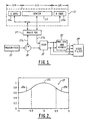
- Figure 1 is a block diagram of a preferred embodiment of the invention.
- Figure 2 a graph of an amplitude distribution which may be applied to the elements of the antenna of Figure 1.
- Figure 3A is a radiation pattern for the antenna of Figure 1 in the transmit mode when the amplitude distribution shown in Figure 2 is applied.
- Figure 3B is a radiation pattern of a central section of the antenna of Figure 1 when the central section of the amplitude distribution of Figure 2 is applied.
- Figure 3C is a radiation pattern of the interferometer formed by end sections of the antenna of Figure 1 when the end sections of the amplitude distribution shown in Figure 2 is applied.
- Figure 4 shows radiation patterns established by adding the interferometer pattern of Figure 3C to the central section pattern of Figure 3B and by subtracting the interferometer pattern from the central section pattern.
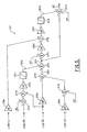
- Figure 5 is a functional block diagram of the video filter of Figure 1.
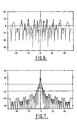
- Figures 6 - 9 are patterns at various stages in the video filter of Figure 1.
- Figure 10 is a radiation pattern of the antenna system provided at the video filter output terminal.
- Figure 11 is a two way radiation pattern of the central and end sections of Figure 1 operating as a continuous antenna.
- Figure 12 is a two way radiation pattern at the video filter output terminals for a two target operating environment.
- Figure 13 is a two way radiation pattern of a conventional antenna for a two target operating environment.
- a segmented antenna system may include an antenna 11 which is of length S.
- the antenna 11 may be divided into three sections, a center section 13 of length S/2 and left 15a and right 15b edge sections, each of length S/4.
- Left edge 15a and the right edge 15b are combined in a manner to form an interferometer having a base line that is equal to 3S/4.
- Interferometer 15a,15b and the center section 13 may be coupled to a magic Tee 17, or other hybrid device, which provides the sum ⁇ and difference ⁇ of the interferometer and center section signals.
- the sum signal output port 17a of the magic Tee 17 may be coupled via a circulator 19 to a receiver 21.
- the difference signal output port 17b of the magic Tee 17 may be coupled directly to the receiver 21.
- a transmitter 23, for providing radiation signals may be respectively coupled to the interferometer 15a,15b and the central section 13 of the antenna 11 via the circulator 19 and the sum signal port of the magic Tee 17. Since the transmitter feeds both the central section 13 and the interferometer 15a,15b simultaneously it provides the radiation signal for the entire antenna 11.
- FIG 2 is an illustration of an antenna illumination function 25 that may be applied over the entire aperture of the antenna 11.
- Figure 3A is the transmit radiation pattern T of the entire aperture of antenna 11;
- Figure 3B is the receive pattern L for the central section 13; and
- Figure 3C is the receive pattern H for the interferometer 15a,15b.
- the four signals (L, H, ⁇ , and ⁇ ) are coupled to the video filter 24 wherein the signals are coupled through logarithmic amplifiers to a processor such as that shown in Figure 5.
- a constant A 1 is added to log( ⁇ ) in summer 27a. This sum is subtracted from log( ⁇ ) in summer 27b and the difference is multiplied by g4 in amplifier 29a. Substraction of logarithms is the equivalent of dividing the antilog of the minuend by the antilog of the subtrahend. Though the constant A 1 is chosen to control the sidelobe level, this division may gives rise to spikes in regions where the ⁇ pattern approaches zero.
- Spike levels may be controlled by coupling the output terminal of the amplifier 29a to a limiter 31a having an output terminal 32a at which a signal representative of log[ ⁇ /(a 1 ⁇ )] g4 is provided, where a 1 is the antilog of A 1 .
- Output terminal 32a of the limiter 31a is coupled to summer 27c, wherein the signal at the output terminal 32a is added to a signal coupled to the summer 27c from the output terminal 32b of summer 27d.
- the signal coupled from the output terminal 32b of summer 27d is the sum of log( ⁇ ) multiplied by g2 in amplifier 29b plus log(H) multiplied by g3 in amplifier 29c, the product being added to A 2 in summer 27e prior to being coupled to summer 27d.
- the signals at the output terminal 32b of summer 27d and the output terminal 32c of summer 27c are respectively representative of log(a 2 ⁇ g2 H g3 ) and log ⁇ a 2 H g3 [ ⁇ g2+g4 /(a 1 ⁇ ) g4 ] ⁇ , where a 2 is the antilog of A 2 .
- Output terminal 32c of summer 27c is coupled to summer 27f wherein a constant A3 is added.
- the signal at the output terminal of summer 27f is multiplied by g5 in amplifier 29d and coupled to summer 27g wherein Log(L), multiplied by g1 in amplifier 29e, is subtracted therefrom.
- the difference signal at the output terminal of summer 27g is multiplied by g6 in amplifier 29f and coupled to limiter 31b having an output terminal 32d at which a signal is provided which is representative of log ⁇ [(a 2 a 3 ) g5g6 /a 1 g4g5g6 ][H g3g5g6 /L g1g6 ][ ⁇ (g2+g4)g5g6 / ⁇ g4g5g6 ] ⁇
- the output terminal 32d of limiter 31b is coupled to summer 27h to which the output terminal 32c of summer 27c and a constant A 4 are also coupled.
- the three signals coupled to summer 27h are added to provide a signal at the output terminal 32e which is representative of log[C(H n1 /L n2 ) ( ⁇ n3 / ⁇ n4 )].
- the beamwidth of the antenna pattern is approximately 1.4°.
- All of the above patterns are two way patterns, i.e. they are the result of transmitting the pattern shown in Figure 3A and processing the received L and H patterns of Figures 3B and 3C, respectively.
- FIG. 12 A two way pattern generated by the segmented antenna 11 and video filter 24 combination is shown in Figure 12.
- the targets are of equal radar cross-section, are at equal ranges, and are in Rayleigh distributed noise with an angular separation of 2.5°.
- Two discernible pattern peaks 35a and 35b, respectively representing target detections, are clearly indicated in Figure 12. These pattern peaks are separated by 2.5° and positioned 1.25° on either side of a deep null 37, no ghost targets are discernible.
- the target indication peaks 35a and 35b in Figure 12 are substantially at the same angular positions as the target indication peaks 39a and 39b in Figure 13.
- the sidelobes 41 in Figure 12 have substantially the same peak levels as the sidelobes 43 in Figure 13.
- the null depth 37 between targets in Figure 12, however, is substantially greater than the null depth 45 between targets for the conventional antenna pattern of Figure 13.
Landscapes
- Engineering & Computer Science (AREA)
- Radar, Positioning & Navigation (AREA)
- Remote Sensing (AREA)
- Computer Networks & Wireless Communication (AREA)
- Physics & Mathematics (AREA)
- General Physics & Mathematics (AREA)
- Radar Systems Or Details Thereof (AREA)
- Variable-Direction Aerials And Aerial Arrays (AREA)
- Aerials With Secondary Devices (AREA)
Description
- The invention pertains to the field of antennas and more particularly to antenna configurations and signal processing of antenna signals for beam narrowing.
- Marine radar antennas are required by the International Electrotechnical Committee (IEC) specifications 936 and 872 to rotate at 20 RPM. Revisions of IEC 936 contain requirements for antennas on High Speed Craft to rotate at 40 RPM while maintaining the azimuth resolution requirements imposed on the 20 RPM antennas. The increased vessel speed and antenna rotation rate requirement, significantly increases the wind loading on the motors that rotationally drive the antenna. Mechanical solutions to this problem have been to enclose the antenna in a radome, thereby shielding it from the wind so that the load on the drive motor is that provided by the antenna alone, placing wings on the antenna to provide better aerodynamic performance, or to provide a more powerful drive motor. All these solutions add significant cost to the radar system.
- It is well known that the radiation beamwidth of an antenna, which determines the angular resolution of the radar system, is a function of its size. Consequently, reducing the sail area of the antenna, while maintaining conventional antenna design and signal processing techniques, increases the radiation beamwidth, thereby adversely effecting the angular resolution of the radar system.
- One technique in the prior art for decreasing the beam width of an antenna of a given size, thereby increasing the angular resolution, utilizes sum and difference signals such as those provided in a monopulse antenna system. Two antennas of equal size and configuration and having independent signal output ports, are placed side-by-side. The signals at the output ports at each half of the antenna are summed and differenced to provide sum and difference signals, the peak of the sum pattern being angular aligned with the null of the difference pattern, thus defining the boresight of the antenna. The sum is divided by the difference, which is a very low signal at boresight. Division by this low signal provides a spike at boresight. As the antenna is rotated from the target position the sum signal decreases while the difference signal increases. This respective decrease and increase of the sum and difference signals causes the ratio of the sum to difference signal pattern to decrease rapidly. Thus, the radiation pattern of the antenna is narrowed and the target position is more accurately determined.
- Though processing the signal returns by dividing the sum signal by the difference signal improves target position accuracy in a single target environment, in a multiple target environment, however, this type of processing may mask true targets and give rise to ghost targets. For example, when two targets having equal radar cross sections are with in the same range bin and are positioned at equal angles on opposite sides of the boresight line, the signal at the output of the sum channel will be that of a target at the antenna's boresight having a radar cross section that is twice that of each target weighted by the level of the antenna sum pattern at the angular position of the targets. Concomitantly, the signal at the output of the difference channel will be a deep null. This results in a ratio of the sum channel output to the difference channel output that is near infinite, a strong indication of a target where there actually is no target, i.e. a ghost target indication.
- Another monopulse technique utilized in the prior art for beam narrowing derives a sum and difference signal, as described above, and, instead of dividing the sum signal by the difference signal, subtracts the magnitude of difference signal from the sum signal. Since the difference signal is at a null on boresight it has little effect on the peak of the sum signal. At angles off boresight, however, the difference signal becomes significant and its subtraction from the sum signal appreciably reduces the composite signal. If the difference pattern has levels at the angular positions of the 3dB points of the sum pattern that are equal to these 3dB levels, the composite signal is zero at these angular positions. When these conditions are met the beam width of the composite antenna pattern is effectively one half that of the sum pattern beam width.
- Monopulse subtraction processing provides a somewhat better multi-target performance than monopulse division processing. In monopulse subtraction processing, two targets within the difference beam, at equal angles on either side of the boresight line, add to provide a signal that appears to be on the boresight line. When this signal is subtracted from the sum beam signal, which is the sum of the two target signals in the sum beam, a null, which is a function of the angular position of the two targets, appears on boresight at the composite signal output. Thus, the ghost target at the boresight midway between the two targets is eliminated. When the antenna is scanned from its target balanced position, the two targets become asymmetrically positioned relative to the antenna boresight line, one providing a greater return in the sum pattern than the other. When the peak of the sum beam is at the one target position a deep null appears in the difference pattern, thus permitting the resolution of the two targets.
- The composite signal output of monopulse subtraction processing, however, exhibits relatively high sidelobe levels. This is due to the fact that the level of the difference pattern lobes in the sidelobe region of the sum beam is appreciably greater than the sidelobe level of the sum beam. Consequently, subtracting the much greater signal of the difference pattern from the sidelobe of the sum pattern creates an undesirable high sidelobe level for the composite signal pattern, which may adversely effect target location determination.
- An antenna of the prior art which reduces the sidelobes of an antenna in a desired direction is disclosed in U.S. Patent No. 5,343,211. In accordance with this invention, a segmented antenna comprising an interferometer (monopulse) antenna, which generates a plurality of lobes of approximately equal amplitude, and a phased array main antenna. The interferometer is provided with elements on the extreme ends of the phased array main antenna. The pattern of the interferometer is subtracted from that of the main antenna and phased such that one of its lobes overlies the sidelobes of the phased array main antenna in the desired direction. This results in significantly reduced sidelobes of the composite antenna in the desired direction.
- The present invention provides an antenna as defined in
claim 1 hereinafter. The antenna may include any one or more features ofdependent claims 2 to 12. - The present invention also provides a method as defined in
claim 13 hereinafter. The method may include any one or more features of dependent claims 14 to 14. - A benefit of this invention may be to provide an antenna and signal processor which has low sidelobes and improves the target resolution and position determination accuracy over that obtainable from a conventional antenna of equal size.
- In accordance with the principles of the invention, an antenna of predetermined length is divided into three sections, two sections are combined as an interferometer and the third is a continuous antenna which has a main lobe that is broader than the lobes of the interferometer. The antenna has two modes of operation, transmit and receive. In the transmit mode, the three sections are combined to form a single antenna having a radiation pattern that is determined by the illumination function, which is chosen to provide a desired sidelobe level for the transmit beam. In the receive mode, the continuous antenna section, which is illuminated by a portion of the illumination function, forms an antenna that is apart from the two sections that form the interferometer. The sections forming the interferometer are illuminated by the remainder of the illumination function. Output signals of the interferometer are added to and subtracted from the output signal of the center section. These sum and difference signals are coupled to a video filter wherein they are processed to provide a narrow beamwidth low sidelobe antenna pattern.
- The invention will be more clearly understood from the following description of an embodiment thereof with reference to the accompanying drawings. It should be understood that the embodiment described is an example of the invention and other embodiments may be implemented within the purview of the invention.
- Figure 1 is a block diagram of a preferred embodiment of the invention.
- Figure 2 a graph of an amplitude distribution which may be applied to the elements of the antenna of Figure 1.
- Figure 3A is a radiation pattern for the antenna of Figure 1 in the transmit mode when the amplitude distribution shown in Figure 2 is applied.
- Figure 3B is a radiation pattern of a central section of the antenna of Figure 1 when the central section of the amplitude distribution of Figure 2 is applied.
- Figure 3C is a radiation pattern of the interferometer formed by end sections of the antenna of Figure 1 when the end sections of the amplitude distribution shown in Figure 2 is applied.
- Figure 4 shows radiation patterns established by adding the interferometer pattern of Figure 3C to the central section pattern of Figure 3B and by subtracting the interferometer pattern from the central section pattern.
- Figure 5 is a functional block diagram of the video filter of Figure 1.
- Figures 6 - 9 are patterns at various stages in the video filter of Figure 1.
- Figure 10 is a radiation pattern of the antenna system provided at the video filter output terminal.
- Figure 11 is a two way radiation pattern of the central and end sections of Figure 1 operating as a continuous antenna.
- Figure 12 is a two way radiation pattern at the video filter output terminals for a two target operating environment.
- Figure 13 is a two way radiation pattern of a conventional antenna for a two target operating environment.
- Refer now to Figure 1. A segmented antenna system may include an
antenna 11 which is of length S. Theantenna 11 may be divided into three sections, acenter section 13 of length S/2 and left 15a and right 15b edge sections, each of length S/4. Left edge 15a and the right edge 15b are combined in a manner to form an interferometer having a base line that is equal to 3S/4. Interferometer 15a,15b and thecenter section 13 may be coupled to amagic Tee 17, or other hybrid device, which provides the sum Σ and difference Δ of the interferometer and center section signals. The sumsignal output port 17a of themagic Tee 17 may be coupled via acirculator 19 to areceiver 21. The difference signal output port 17b of themagic Tee 17 may be coupled directly to thereceiver 21. Since the interferometer 13a,13b has a base line that is longer than the length of thecentral section 13, it produces an antenna pattern which is narrower than the antenna pattern produced by the central section. Consequently, the interferometer 15a,15b has a higher resolution capability than the central section. Due the higher resolution capability of the interferometer 15a, 15b, in the description to follow, its output signal will be designated H, high resolution, and thecentral section 13 output signal will be designated L, low resolution. Signals representative of the sum Σ and difference Δ signals are coupled from thereceiver 21 to a power divider andhybrid circuit 22 wherein signals representative of the high H and the low L signals are derived from H = (Σ - Δ)/2 and L = (Σ + Δ)/2. These high H and low L representative signals are coupled to avideo filter 24, to which signals representative of the sum Σ and difference Δ signals are also coupled. Atransmitter 23, for providing radiation signals, may be respectively coupled to the interferometer 15a,15b and thecentral section 13 of theantenna 11 via thecirculator 19 and the sum signal port of themagic Tee 17. Since the transmitter feeds both thecentral section 13 and the interferometer 15a,15b simultaneously it provides the radiation signal for theentire antenna 11. - Figure 2 is an illustration of an
antenna illumination function 25 that may be applied over the entire aperture of theantenna 11. Theillustrative function 25 is a standard Taylor taper having defining parametersn = 2 and sidelobe level (sl) = 16dB. It should be understood that this distribution function is not limiting and that other illumination functions may be used. Since the distribution is over the entire aperture, the left 15a and right 15b edge sections have distribution functions 25a and 25b, respectively, while thecentral portion 13 has the distribution function 25c. For S equal to 22.5λ (λ is the operating wavelength of the antenna), the aperture distribution function of Figure 2 gives rise to the antenna patterns shown in Figures 3A - 3C. Figure 3A is the transmit radiation pattern T of the entire aperture ofantenna 11; Figure 3B is the receive pattern L for thecentral section 13; and Figure 3C is the receive pattern H for the interferometer 15a,15b. The sum Σ = L + H and difference Δ = L -H patterns at the output of themagic Tee 17 are shown in Figure 4. - The four signals (L, H, Σ, and Δ) are coupled to the
video filter 24 wherein the signals are coupled through logarithmic amplifiers to a processor such as that shown in Figure 5. A constant A1 is added to log(Δ) in summer 27a. This sum is subtracted from log(Σ) insummer 27b and the difference is multiplied by g4 inamplifier 29a. Substraction of logarithms is the equivalent of dividing the antilog of the minuend by the antilog of the subtrahend. Though the constant A1 is chosen to control the sidelobe level, this division may gives rise to spikes in regions where the Δ pattern approaches zero. Spike levels may be controlled by coupling the output terminal of theamplifier 29a to a limiter 31a having an output terminal 32a at which a signal representative of log[Σ/(a1 Δ)]g4 is provided, where a1 is the antilog of A1. With A1 = 0 (a1 = 1) and g4 = 1, the pattern at the output terminal 32a of limiter 31a, as a function of antenna azimuth angle from a fixed target, is given in Figure 6. - Output terminal 32a of the limiter 31a is coupled to
summer 27c, wherein the signal at the output terminal 32a is added to a signal coupled to thesummer 27c from theoutput terminal 32b ofsummer 27d. The signal coupled from theoutput terminal 32b ofsummer 27d is the sum of log(Σ) multiplied by g2 inamplifier 29b plus log(H) multiplied by g3 inamplifier 29c, the product being added to A2 insummer 27e prior to being coupled tosummer 27d. The signals at theoutput terminal 32b ofsummer 27d and theoutput terminal 32c ofsummer 27c are respectively representative of log(a2Σg2Hg3) and log {a2Hg3[Σ g2+g4/(a1 Δ)g4]}, where a2 is the antilog of A2. Patterns at theterminals -
Output terminal 32c ofsummer 27c is coupled tosummer 27f wherein a constant A3 is added. The signal at the output terminal ofsummer 27f is multiplied by g5 inamplifier 29d and coupled tosummer 27g wherein Log(L), multiplied by g1 inamplifier 29e, is subtracted therefrom. The difference signal at the output terminal ofsummer 27g is multiplied by g6 inamplifier 29f and coupled tolimiter 31b having an output terminal 32d at which a signal is provided which is representative of - A pattern for this signal is given in Figure 9, when A1=0, A2=-18, g2=g3=0.5, g4=g5=g6=1.
- The output terminal 32d of
limiter 31b is coupled tosummer 27h to which theoutput terminal 32c ofsummer 27c and a constant A4 are also coupled. The three signals coupled tosummer 27h are added to provide a signal at the output terminal 32e which is representative of - Thus the sharpened antenna pattern is given by:
- C = (a2a3)g5g6a2a4/a1 g4(1 + g5g6)
- n1 = g3(1 + g5g6)
- n2 = g1g6
- n3 = (g2 + g4)(1 + g5g6)
- n4 = g4(1 + g5g6)
-
- The output pattern of the video filter, the desired antenna pattern, when A1=A4=0, A2=-18, A3=6, g1=g4=g5=g6=1, and g2=g3=0.5 is shown in Figure 10. The beamwidth of the antenna pattern is approximately 1.4°.
- All of the above patterns are two way patterns, i.e. they are the result of transmitting the pattern shown in Figure 3A and processing the received L and H patterns of Figures 3B and 3C, respectively. As stated above, the antenna has an overall length of 22.5λ and a Taylor distribution with
n = 2 and sl = 16dB over the entire antenna. A conventional antenna having a length of 22.5λ and a Taylor distribution withn = 2 and sl = 16dB will have an antenna pattern as shown in Figure 11. It is apparent from these Figures that a significant reduction in the beamwidth and sidelobe levels has been achieved with the segmented antenna and the video filter. - The above discussion has considered but one target. In a multiple target environment the beam narrowing realized with the
segmented antenna 11 and the signal processing performed by thevideo filter 24 provides significant improvements in target resolution over that achievable with a conventional antenna of equal size without generating ghost targets. A two way pattern generated by the segmentedantenna 11 andvideo filter 24 combination is shown in Figure 12. The targets are of equal radar cross-section, are at equal ranges, and are in Rayleigh distributed noise with an angular separation of 2.5°. The video filter processing parameters for the pattern of Figure 12 are: A1=8; A2=1; A3=A4=0; g1=g4=g5=g6=1; g2=g3=0.5. Two discernible pattern peaks 35a and 35b, respectively representing target detections, are clearly indicated in Figure 12. These pattern peaks are separated by 2.5° and positioned 1.25° on either side of adeep null 37, no ghost targets are discernible. A conventional antenna having a length equal to the length of the segmentedantenna 11 and a Taylor aperture taper withn =2 and sl=16dB would have a beam width of approximately 2.8°. This conventional antenna would not be able to resolve two targets with 2.5° of angular separation. - A comparison of the two target pattern generated by the segmented
antenna 11 with thevideo filter 24 processor to a two target pattern, shown in Figure 13, generated by a conventional antenna having a length twice that of the segmented antenna, indicates the superior performance of the segmented antenna system. The target indication peaks 35a and 35b in Figure 12 are substantially at the same angular positions as the target indication peaks 39a and 39b in Figure 13. Thesidelobes 41 in Figure 12 have substantially the same peak levels as thesidelobes 43 in Figure 13. Thenull depth 37 between targets in Figure 12, however, is substantially greater than thenull depth 45 between targets for the conventional antenna pattern of Figure 13.
Claims (20)
- An antenna system including an antenna (11) segmented and arranged to provide a first received signal at a first port and a second received signal at a second port, said second port coupled to segments of said antenna in a manner to establish an interferometer, characterized in that it further comprises;hybrid means (17) coupled to said first and second ports for adding said first received signal to said second received signal and for subtracting said first received signal from said second received signal, thereby forming sum and difference signals, respectively; andprocessing means(21,22,24)coupled to receive said sum signal and said difference signal for processing said sum and difference signals in a manner to provide antenna beam sharpened signals.
- An antenna system in accordance with claim 1 wherein said antenna is segmented in a manner to provide a central section (13) and two end sections (15a,15b), said two end sections coupled to said second port to form said interferometer.
- An antenna system in accordance claim 2 wherein said antenna is of length S, said central section (13) is of length S/2, and each end section (15a,15b) is of length S/4.
- An antenna system in accordance claim 2 wherein said processing means includes:means (22) for extracting said first and second signals from said sum and difference signals; andfilter means (24) coupled to receive said first and second signals and said sum and difference signals for providing said antenna beam sharpened signals.
- An antenna system in accordance claim 4 wherein said filter means includes:logarithmic amplifier means coupled to receive said first and second signals and said sum and difference signals for providing first and second log signals representative of logarithms of said first and second signals, respectively, and sum and difference log signals representative of logarithms of said sum and difference signals, respectively;first sum means (27a,27b,27c,27d,27e) coupled to receive said sum and difference log signals and said second log signals for providing first addition signals representative of additions of said second log signals to signals representative of subtractions of said difference log signals from said sum log signals;second sum means (27f,27g)coupled to receive said first addition signals and said first log signals for providing second addition signals representative of said first log signals subtracted from said first addition log signals; andthird sum means (27h) coupled to said first and second sum means for providing signals representative of additions of said first and second addition signals, thereby providing said antenna beam sharpened signals.
- An antenna system in accordance claim 5 wherein said first sum means (27a,27b,27c,27d,27e)include first amplifier means (29a,29b,29c,29d) for respectively multiplying said second log signals, said sum log signals, said difference log signals, and said first addition signals and wherein said second sum means (27f,27g) includes second amplifier means (29e,29f) for respectively, multiplying said first log signals and said second addition signals.
- An antenna system in accordance claim 6 wherein said first sum means (27a,27b,27c,27d,27e) includes means for respectively adding constants to said second log signals and to said difference log signals, said second sum means (27f,27g)includes means for adding a constant to said first addition signals, and said third sum means (32) includes means for adding a constant to said additions of said first and second addition signals.
- An antenna system in accordance claim 1 wherein said processing means (21,22,24)includes:means (22) for extracting said first and second signals from said sum and difference signals; andfilter means (24) coupled to receive said first and second signals and said sum and difference signals for providing said antenna beam sharpened signals.
- An antenna system in accordance claim 8 wherein said filter means includes:logarithmic amplifier means coupled to receive said first and second signals and said sum and difference signals for providing first and second log signals representative of logarithms of said first and second signals, respectively, and sum and difference log signals representative of logarithms of said sum and difference signals, respectively;first sum means (27a,27b, 27c,27d,27e) coupled to receive said sum and difference log signals and said second log signals for providing first addition signals representative of additions of said second log signals to signals representative of subtractions of said difference log signals from said sum log signals;second sum means (27f,27g)coupled to receive said first addition signals and said first log signals for providing second addition signals representative of said first log signals subtracted from said first addition log signals; andthird sum means (27h) coupled to said first and second sum means for providing signals representative of additions of said first and second addition signals, thereby providing said antenna beam sharpened signals.
- An antenna system in accordance claim 9 wherein said first sum means (27a,27b,27c,27d,27e)include first amplifier means ((29a,29b,29c,29d) for respectively multiplying said second log signals, said sum log signals, said difference log signals, and said first addition signals and wherein said second sum means (27f,27g) includes second amplifier means (29e,29f) for respectively, multiplying said first log signals and said second addition signals.
- An antenna system in accordance claim 10 wherein said first sum means (27a,27b,27c,27d,27e) includes means for respectively adding constants to said second log signals and to said difference log signals, said second sum means (27f,27g)includes means for adding a constant to said first addition signals, and said third sum means (32) includes means for adding a constant to said additions of said first and second addition signals.
- An antenna in accordance with claim 3 further including means (19) coupled to said hybrid means and said processing means for coupling a transmitter (23) to said first and second ports in a manner to provide radiation from an antenna of length S.
- A method for narrowing the beam of an antenna of predetermined size including the steps of segmenting said antenna to establish first and second sub-antennas, said second sub-antenna arranged to form an interferometer characterized in that the method further includes the steps of:coupling said first and second sub-antennas to provide signals representative of sum and difference of first and second signals at output ports of said first and second sub-antennas, respectively; andprocessing said sum and difference representative signals in a manner to provide a beam narrowed signal.
- A method in accordance with claim 13 wherein said processing step includes the steps of:extracting said first and second signals from said sum and difference representative signals;coupling said first and second signals and said sum and difference representative signals to logarithmic amplifiers to obtain first and second log signals and sum and difference log signals;subtracting said log difference signal from said sum log signal to provide a subtraction log signal;adding said second log signal to said sum log signal to provide a sub-addition signai;adding said sub-addition signal to said subtraction log signal to provide a first addition signal;subtracting said first log signal from said first addition signal to provide a second addition signal; andadding said first and second addition signals to provide antenna beam narrowed signal.
- A method in accordance with claim 14 further includes the steps of:multiplying said subtraction log signal by a first predetermined multiplicative constant;multiplying said sum log signal and said second log signal by second and third multiplicative constants, respectively;multiplying said first log signal and said first addition signal by fourth and fifth predetermined multiplicative constants, respectively; andmultiplying said second addition signal by a sixth predetermined constant.
- A method in accordance with claim 15 further including the steps of adding preselected constants to said log difference signal, said second signal, said first addition signal, and to said beam narrowed signal, respectively.
- A method in accordance with claim 13 wherein said antenna is of length S, said first sub-antenna is of length S/2 and is a central section of said antenna and said second sub-antenna comprises two end sections of said antenna,each of length S/4.
- A method in accordance with claim 17 further including the step of coupling said central and said two end sections in a manner to provide an antenna with a radiating aperture of length S.
- A method in accordance with claim 13 wherein said processing step includes the steps of:adding said sum and difference representative signals to obtain said first signal; andsubtracting said difference signal from said sum signal to obtain said second signal.
- A method in accordance with claim 18 wherein said processing step further includes the steps of:passing said first and second signals and said sum and difference representative signals through logarithmic amplifiers to respectively obtain first and second log signals and sum and difference log signals;utilizing said first and second log signals and said sum and difference log signals to provide said beam narrowed.
Applications Claiming Priority (3)
| Application Number | Priority Date | Filing Date | Title |
|---|---|---|---|
| US08/675,977 US5754140A (en) | 1996-07-05 | 1996-07-05 | Beam sharpened, low sidelobe antenna system |
| US675977 | 1996-07-05 | ||
| PCT/US1997/011387 WO1998001771A1 (en) | 1996-07-05 | 1997-07-01 | A beam sharpened, low sidelobe antenna system |
Publications (2)
| Publication Number | Publication Date |
|---|---|
| EP0909396A1 EP0909396A1 (en) | 1999-04-21 |
| EP0909396B1 true EP0909396B1 (en) | 2001-10-17 |
Family
ID=24712708
Family Applications (1)
| Application Number | Title | Priority Date | Filing Date |
|---|---|---|---|
| EP97933223A Expired - Lifetime EP0909396B1 (en) | 1996-07-05 | 1997-07-01 | A beam sharpened, low sidelobe antenna system |
Country Status (7)
| Country | Link |
|---|---|
| US (1) | US5754140A (en) |
| EP (1) | EP0909396B1 (en) |
| JP (1) | JP3432231B2 (en) |
| CA (1) | CA2258126C (en) |
| DE (1) | DE69707458T2 (en) |
| NO (1) | NO317455B1 (en) |
| WO (1) | WO1998001771A1 (en) |
Families Citing this family (9)
| Publication number | Priority date | Publication date | Assignee | Title |
|---|---|---|---|---|
| US7099696B2 (en) * | 2003-02-14 | 2006-08-29 | Radio Frequency Systems, Inc. | Angle diversity dual antenna system |
| US7548194B2 (en) * | 2006-03-14 | 2009-06-16 | Raytheon Company | Hostile intention assessment system and method |
| US7796082B2 (en) * | 2007-02-08 | 2010-09-14 | Raytheon Company | Methods and apparatus for log-FTC radar receivers having enhanced sea clutter model |
| US7750840B2 (en) * | 2007-12-04 | 2010-07-06 | Raytheon Company | Method and apparatus for assessing contact clusters |
| WO2011068442A1 (en) * | 2009-12-01 | 2011-06-09 | Saab Ab | Method for angular focusing of signals in scanning radar systems |
| US8174435B2 (en) | 2010-06-01 | 2012-05-08 | Raytheon Company | Methods and apparatus for non-isotropic sea clutter modeling |
| US8456350B2 (en) | 2010-12-17 | 2013-06-04 | Raytheon Company | Methods and apparatus for sea state measurement via radar sea clutter eccentricity |
| US8456352B2 (en) | 2010-12-17 | 2013-06-04 | Raytheon Company | Methods and apparatus for automatic STC from sea state measurement via radar sea clutter eccentricity |
| CN107271989B (en) * | 2017-05-27 | 2019-12-20 | 西北工业大学 | Low-beam sidelobe MIMO sonar array with optimal rotation angle |
Family Cites Families (9)
| Publication number | Priority date | Publication date | Assignee | Title |
|---|---|---|---|---|
| GB1056352A (en) * | 1963-07-29 | 1967-01-25 | Marconi Co Ltd | Improvements in or relating to aerial systems |
| NL6812918A (en) * | 1968-09-10 | 1970-03-12 | ||
| US3618092A (en) | 1969-05-23 | 1971-11-02 | North American Rockwell | Signal injection apparatus for avoiding monopulse anomalies in a monopulse array |
| FR2455369A1 (en) * | 1979-04-25 | 1980-11-21 | Thomson Csf | Monopulse antenna with two planar arrays - enlarges measuring angle by providing uniformly distributed wave energy |
| GB2135828B (en) * | 1983-02-24 | 1986-03-05 | Cossor Electronics Ltd | A monopulse radar antenna |
| GB2191650A (en) * | 1986-06-10 | 1987-12-16 | Philips Electronic Associated | Wave signal direction-finding |
| US4827270A (en) | 1986-12-22 | 1989-05-02 | Mitsubishi Denki Kabushiki Kaisha | Antenna device |
| US5343211A (en) * | 1991-01-22 | 1994-08-30 | General Electric Co. | Phased array antenna with wide null |
| US5506589A (en) * | 1993-04-09 | 1996-04-09 | Hughes Aircraft Company | Monopulse array system with air-stripline multi-port network |
-
1996
- 1996-07-05 US US08/675,977 patent/US5754140A/en not_active Expired - Lifetime
-
1997
- 1997-07-01 JP JP50525798A patent/JP3432231B2/en not_active Expired - Fee Related
- 1997-07-01 EP EP97933223A patent/EP0909396B1/en not_active Expired - Lifetime
- 1997-07-01 WO PCT/US1997/011387 patent/WO1998001771A1/en not_active Ceased
- 1997-07-01 DE DE69707458T patent/DE69707458T2/en not_active Expired - Lifetime
- 1997-07-01 CA CA002258126A patent/CA2258126C/en not_active Expired - Fee Related
-
1998
- 1998-12-18 NO NO19985990A patent/NO317455B1/en not_active IP Right Cessation
Also Published As
| Publication number | Publication date |
|---|---|
| DE69707458T2 (en) | 2002-05-16 |
| NO985990D0 (en) | 1998-12-18 |
| CA2258126A1 (en) | 1998-01-15 |
| JP3432231B2 (en) | 2003-08-04 |
| JP2000515338A (en) | 2000-11-14 |
| DE69707458D1 (en) | 2001-11-22 |
| NO985990L (en) | 1999-03-04 |
| WO1998001771A1 (en) | 1998-01-15 |
| US5754140A (en) | 1998-05-19 |
| CA2258126C (en) | 2003-09-23 |
| EP0909396A1 (en) | 1999-04-21 |
| NO317455B1 (en) | 2004-11-01 |
Similar Documents
| Publication | Publication Date | Title |
|---|---|---|
| US20130088393A1 (en) | Transmit and receive phased array for automotive radar improvement | |
| US4912477A (en) | Radar system for determining angular position utilizing a linear phased array antenna | |
| US5754140A (en) | Beam sharpened, low sidelobe antenna system | |
| EP0913706B1 (en) | IFF systems | |
| EP0312588A1 (en) | Multifunction active array. | |
| EP1169652B1 (en) | Off-axis indicator algorithm for monopulse radar | |
| US5025493A (en) | Multi-element antenna system and array signal processing method | |
| JP3525388B2 (en) | Radar equipment | |
| WO2022229386A1 (en) | Mimo radar using a frequency scanning antenna | |
| US5982319A (en) | UHF synthetic aperture radar | |
| Araki et al. | Wide scanning phased array antenna design in Ka band | |
| US6377212B1 (en) | Radar apparatus employing a sidelobe blanking system | |
| US5905463A (en) | Linear array aircraft antenna with coning correction | |
| US5252983A (en) | Method for reducing side lobes in antenna patterns | |
| KR100456356B1 (en) | How to narrow the beam width of a specified size antenna and antenna system | |
| JPH0682980B2 (en) | Monopulse antenna with improved sidelobe suppression | |
| EP1301804A2 (en) | Simultaneous nulling in low sidelobe sum and difference antenna beam patterns | |
| KR20210046545A (en) | Array antenna device for using spatial power spectrum combining and thereof controlling method | |
| EP0141886B1 (en) | Monopulse detection systems | |
| GB2303266A (en) | Sidelobe supression radar | |
| Cole | Adaptive antenna subsystems | |
| EP1067396A2 (en) | Self-guarding monopulse antenna | |
| Sullivan | Selection of Optimum Antennas for Tracking Telemetry Instrumented Airborne Vehicles | |
| BOESSWETTER | ECCM effectiveness of a low sidelobe antenna for SAR ground mapping(Abstract Only) | |
| CN120858492A (en) | Antenna system, radar, terminal equipment and vehicle terminal |
Legal Events
| Date | Code | Title | Description |
|---|---|---|---|
| PUAI | Public reference made under article 153(3) epc to a published international application that has entered the european phase |
Free format text: ORIGINAL CODE: 0009012 |
|
| 17P | Request for examination filed |
Effective date: 19981218 |
|
| AK | Designated contracting states |
Kind code of ref document: A1 Designated state(s): BE DE DK ES FI FR GB IT NL PT SE |
|
| 17Q | First examination report despatched |
Effective date: 20000208 |
|
| GRAG | Despatch of communication of intention to grant |
Free format text: ORIGINAL CODE: EPIDOS AGRA |
|
| GRAG | Despatch of communication of intention to grant |
Free format text: ORIGINAL CODE: EPIDOS AGRA |
|
| GRAH | Despatch of communication of intention to grant a patent |
Free format text: ORIGINAL CODE: EPIDOS IGRA |
|
| GRAH | Despatch of communication of intention to grant a patent |
Free format text: ORIGINAL CODE: EPIDOS IGRA |
|
| GRAA | (expected) grant |
Free format text: ORIGINAL CODE: 0009210 |
|
| AK | Designated contracting states |
Kind code of ref document: B1 Designated state(s): BE DE DK ES FI FR GB IT NL PT SE |
|
| PG25 | Lapsed in a contracting state [announced via postgrant information from national office to epo] |
Ref country code: NL Free format text: LAPSE BECAUSE OF FAILURE TO SUBMIT A TRANSLATION OF THE DESCRIPTION OR TO PAY THE FEE WITHIN THE PRESCRIBED TIME-LIMIT Effective date: 20011017 Ref country code: FI Free format text: LAPSE BECAUSE OF FAILURE TO SUBMIT A TRANSLATION OF THE DESCRIPTION OR TO PAY THE FEE WITHIN THE PRESCRIBED TIME-LIMIT Effective date: 20011017 Ref country code: BE Free format text: LAPSE BECAUSE OF FAILURE TO SUBMIT A TRANSLATION OF THE DESCRIPTION OR TO PAY THE FEE WITHIN THE PRESCRIBED TIME-LIMIT Effective date: 20011017 |
|
| REF | Corresponds to: |
Ref document number: 69707458 Country of ref document: DE Date of ref document: 20011122 |
|
| REG | Reference to a national code |
Ref country code: GB Ref legal event code: IF02 |
|
| ET | Fr: translation filed | ||
| PG25 | Lapsed in a contracting state [announced via postgrant information from national office to epo] |
Ref country code: SE Free format text: LAPSE BECAUSE OF FAILURE TO SUBMIT A TRANSLATION OF THE DESCRIPTION OR TO PAY THE FEE WITHIN THE PRESCRIBED TIME-LIMIT Effective date: 20020117 Ref country code: PT Free format text: LAPSE BECAUSE OF FAILURE TO SUBMIT A TRANSLATION OF THE DESCRIPTION OR TO PAY THE FEE WITHIN THE PRESCRIBED TIME-LIMIT Effective date: 20020117 Ref country code: DK Free format text: LAPSE BECAUSE OF FAILURE TO SUBMIT A TRANSLATION OF THE DESCRIPTION OR TO PAY THE FEE WITHIN THE PRESCRIBED TIME-LIMIT Effective date: 20020117 |
|
| NLV1 | Nl: lapsed or annulled due to failure to fulfill the requirements of art. 29p and 29m of the patents act | ||
| PG25 | Lapsed in a contracting state [announced via postgrant information from national office to epo] |
Ref country code: ES Free format text: LAPSE BECAUSE OF FAILURE TO SUBMIT A TRANSLATION OF THE DESCRIPTION OR TO PAY THE FEE WITHIN THE PRESCRIBED TIME-LIMIT Effective date: 20020430 |
|
| PLBE | No opposition filed within time limit |
Free format text: ORIGINAL CODE: 0009261 |
|
| STAA | Information on the status of an ep patent application or granted ep patent |
Free format text: STATUS: NO OPPOSITION FILED WITHIN TIME LIMIT |
|
| 26N | No opposition filed | ||
| REG | Reference to a national code |
Ref country code: GB Ref legal event code: 732E Free format text: REGISTERED BETWEEN 20111103 AND 20111109 |
|
| REG | Reference to a national code |
Ref country code: DE Ref legal event code: R082 Ref document number: 69707458 Country of ref document: DE Representative=s name: G. KOCH UND KOLLEGEN, DE Effective date: 20111201 Ref country code: DE Ref legal event code: R081 Ref document number: 69707458 Country of ref document: DE Owner name: NORTHROP GRUMMAN SYSTEMS CORPORATION (N.D.GES., US Free format text: FORMER OWNER: SPERRY MARINE, INC., CHARLOTTESVILLE, VA., US Effective date: 20111201 Ref country code: DE Ref legal event code: R081 Ref document number: 69707458 Country of ref document: DE Owner name: NORTHROP GRUMMAN SYSTEMS CORPORATION (N.D.GES., US Free format text: FORMER OWNER: SPERRY MARINE, INC., CHARLOTTESVILLE, US Effective date: 20111201 Ref country code: DE Ref legal event code: R081 Ref document number: 69707458 Country of ref document: DE Owner name: NORTHROP GRUMMAN SYSTEMS CORP. (N.D.GES.D. STA, US Free format text: FORMER OWNER: SPERRY MARINE, INC., CHARLOTTESVILLE, US Effective date: 20111201 |
|
| REG | Reference to a national code |
Ref country code: DE Ref legal event code: R082 Ref document number: 69707458 Country of ref document: DE Representative=s name: G. KOCH UND KOLLEGEN, DE Effective date: 20120726 Ref country code: DE Ref legal event code: R081 Ref document number: 69707458 Country of ref document: DE Owner name: NORTHROP GRUMMAN SYSTEMS CORPORATION (N.D.GES., US Free format text: FORMER OWNER: NORTHROP GRUMMAN CORP. (N.D.GES.D.STAATES DELAWARE), LOS ANGELES, CALIF., US Effective date: 20120726 Ref country code: DE Ref legal event code: R081 Ref document number: 69707458 Country of ref document: DE Owner name: NORTHROP GRUMMAN SYSTEMS CORPORATION (N.D.GES., US Free format text: FORMER OWNER: NORTHROP GRUMMAN CORP. (N.D.GES.D.STAATES DELAWARE), LOS ANGELES, US Effective date: 20120726 Ref country code: DE Ref legal event code: R081 Ref document number: 69707458 Country of ref document: DE Owner name: NORTHROP GRUMMAN SYSTEMS CORP. (N.D.GES.D. STA, US Free format text: FORMER OWNER: NORTHROP GRUMMAN CORP. (N.D.GES.D.STAATES DELAWARE), LOS ANGELES, US Effective date: 20120726 |
|
| REG | Reference to a national code |
Ref country code: DE Ref legal event code: R082 Ref document number: 69707458 Country of ref document: DE Representative=s name: G. KOCH UND KOLLEGEN, DE |
|
| REG | Reference to a national code |
Ref country code: DE Ref legal event code: R082 Ref document number: 69707458 Country of ref document: DE Representative=s name: G. KOCH UND KOLLEGEN, DE Effective date: 20121211 Ref country code: DE Ref legal event code: R081 Ref document number: 69707458 Country of ref document: DE Owner name: NORTHROP GRUMMAN SYSTEMS CORPORATION (N.D.GES., US Free format text: FORMER OWNER: NORTHROP GRUMMAN SYSTEMS CORP. (N.D.GES.D. STAATES DELAWARE), LOS ANGELES, CALIF., US Effective date: 20121211 Ref country code: DE Ref legal event code: R081 Ref document number: 69707458 Country of ref document: DE Owner name: NORTHROP GRUMMAN SYSTEMS CORPORATION (N.D.GES., US Free format text: FORMER OWNER: NORTHROP GRUMMAN SYSTEMS CORP. (N.D.GES.D. STAATES DELAWARE), LOS ANGELES, US Effective date: 20121211 |
|
| PGFP | Annual fee paid to national office [announced via postgrant information from national office to epo] |
Ref country code: DE Payment date: 20130722 Year of fee payment: 17 |
|
| PGFP | Annual fee paid to national office [announced via postgrant information from national office to epo] |
Ref country code: GB Payment date: 20130719 Year of fee payment: 17 Ref country code: FR Payment date: 20130722 Year of fee payment: 17 |
|
| PGFP | Annual fee paid to national office [announced via postgrant information from national office to epo] |
Ref country code: IT Payment date: 20130729 Year of fee payment: 17 |
|
| REG | Reference to a national code |
Ref country code: DE Ref legal event code: R119 Ref document number: 69707458 Country of ref document: DE |
|
| GBPC | Gb: european patent ceased through non-payment of renewal fee |
Effective date: 20140701 |
|
| REG | Reference to a national code |
Ref country code: FR Ref legal event code: ST Effective date: 20150331 |
|
| PG25 | Lapsed in a contracting state [announced via postgrant information from national office to epo] |
Ref country code: DE Free format text: LAPSE BECAUSE OF NON-PAYMENT OF DUE FEES Effective date: 20150203 Ref country code: IT Free format text: LAPSE BECAUSE OF NON-PAYMENT OF DUE FEES Effective date: 20140701 |
|
| REG | Reference to a national code |
Ref country code: DE Ref legal event code: R119 Ref document number: 69707458 Country of ref document: DE Effective date: 20150203 |
|
| PG25 | Lapsed in a contracting state [announced via postgrant information from national office to epo] |
Ref country code: GB Free format text: LAPSE BECAUSE OF NON-PAYMENT OF DUE FEES Effective date: 20140701 Ref country code: FR Free format text: LAPSE BECAUSE OF NON-PAYMENT OF DUE FEES Effective date: 20140731 |