EP0908380A2 - Electrically driven bicycle - Google Patents
Electrically driven bicycle Download PDFInfo
- Publication number
- EP0908380A2 EP0908380A2 EP98307440A EP98307440A EP0908380A2 EP 0908380 A2 EP0908380 A2 EP 0908380A2 EP 98307440 A EP98307440 A EP 98307440A EP 98307440 A EP98307440 A EP 98307440A EP 0908380 A2 EP0908380 A2 EP 0908380A2
- Authority
- EP
- European Patent Office
- Prior art keywords
- battery case
- battery
- main frame
- case
- electrically driven
- Prior art date
- Legal status (The legal status is an assumption and is not a legal conclusion. Google has not performed a legal analysis and makes no representation as to the accuracy of the status listed.)
- Withdrawn
Links
Images


Classifications
-
- B—PERFORMING OPERATIONS; TRANSPORTING
- B62—LAND VEHICLES FOR TRAVELLING OTHERWISE THAN ON RAILS
- B62M—RIDER PROPULSION OF WHEELED VEHICLES OR SLEDGES; POWERED PROPULSION OF SLEDGES OR SINGLE-TRACK CYCLES; TRANSMISSIONS SPECIALLY ADAPTED FOR SUCH VEHICLES
- B62M6/00—Rider propulsion of wheeled vehicles with additional source of power, e.g. combustion engine or electric motor
- B62M6/40—Rider propelled cycles with auxiliary electric motor
- B62M6/60—Rider propelled cycles with auxiliary electric motor power-driven at axle parts
-
- B—PERFORMING OPERATIONS; TRANSPORTING
- B62—LAND VEHICLES FOR TRAVELLING OTHERWISE THAN ON RAILS
- B62M—RIDER PROPULSION OF WHEELED VEHICLES OR SLEDGES; POWERED PROPULSION OF SLEDGES OR SINGLE-TRACK CYCLES; TRANSMISSIONS SPECIALLY ADAPTED FOR SUCH VEHICLES
- B62M6/00—Rider propulsion of wheeled vehicles with additional source of power, e.g. combustion engine or electric motor
- B62M6/80—Accessories, e.g. power sources; Arrangements thereof
- B62M6/90—Batteries
-
- B—PERFORMING OPERATIONS; TRANSPORTING
- B60—VEHICLES IN GENERAL
- B60K—ARRANGEMENT OR MOUNTING OF PROPULSION UNITS OR OF TRANSMISSIONS IN VEHICLES; ARRANGEMENT OR MOUNTING OF PLURAL DIVERSE PRIME-MOVERS IN VEHICLES; AUXILIARY DRIVES FOR VEHICLES; INSTRUMENTATION OR DASHBOARDS FOR VEHICLES; ARRANGEMENTS IN CONNECTION WITH COOLING, AIR INTAKE, GAS EXHAUST OR FUEL SUPPLY OF PROPULSION UNITS IN VEHICLES
- B60K1/00—Arrangement or mounting of electrical propulsion units
- B60K1/04—Arrangement or mounting of electrical propulsion units of the electric storage means for propulsion
-
- B—PERFORMING OPERATIONS; TRANSPORTING
- B60—VEHICLES IN GENERAL
- B60Y—INDEXING SCHEME RELATING TO ASPECTS CROSS-CUTTING VEHICLE TECHNOLOGY
- B60Y2200/00—Type of vehicle
- B60Y2200/10—Road Vehicles
- B60Y2200/13—Bicycles; Tricycles
Definitions
- the present invention relates to an electrically driven bicycle, and more particularly to an electrically driven bicycle which utilizes a driving power of a motor for assisting a human driving power or which utilizes the driving power of the motor as a main driving power for traveling.
- the present invention relates to an electrically driven bicycle in which a shape of a battery case and a configuration of a battery are improved so that a user can ride on and off the bicycle smoothly and can travel in a safe state.
- a motor for driving wheels to assist a human driving power for traveling is mounted and a battery as a driving power source for the motor is mounted on the bicycle.
- a main frame of the bicycle mainly includes a head pipe 104 on which a handlebar 105 is mounted, a standing pipe 102 on which a saddle 106 is mounted, and a main pipe (hidden by a battery case 110 in Fig. 11) bridging the head pipe 104 and the standing pipe 102, and the like.
- a structure is generally known in which the battery case 110 loaded with batteries is disposed on the main pipe, as shown in Fig. 11.
- the battery case 110 may be disposed in the front or in the rear of the standing pipe 102 instead of being disposed on the main pipe.
- the reference numeral 101 represents a driving section incorporating an electric motor, a speed reduction mechanism, a torque sensor, and the like; and the reference numeral 119 represents a frame cover that covers metal fittings provided in the main frame.
- the reference numeral 115 represents a cap for covering a charging connector. The cap 115 prevents intrusion of water and dust.
- the battery case is mounted over or under the main pipe, or in the front or in the rear of the standing pipe, as described above. Therefore, a structure is adopted in which a battery pack is prepared, for example, by making five rows each including four batteries connected in series allowing all the batteries to be connected in series, and the battery pack is inserted into the battery case as it is.
- a battery pack is prepared, for example, by making five rows each including four batteries connected in series allowing all the batteries to be connected in series, and the battery pack is inserted into the battery case as it is.
- each of the batteries has a diameter of about 33mm, the height of the stacked batteries will be very high when the number of the stacked batteries is about three or more. Therefore, a problem arises such that there will be a large protuberance formed by the batteries over the main pipe or in front of the standing pipe, making it difficult to ride on or off the bicycle.
- the batteries are to be disposed in the front or in the rear of the standing pipe
- the saddle if the battery case is to be disposed on the chain case because of the existence of the chain case, the saddle must be mounted at a higher position, so that it will be very difficult for a less tall person to ride the bicycle because the feet cannot reach the ground so easily.
- the batteries are disposed in a space adjacent to the chain case, the batteries are unbalanced, so that the user cannot ride the bicycle in a stable manner and, further, the batteries are not arranged in order, making the wiring complex and increasing the costs.
- the cap for covering the connector prevents intrusion of water and dust.
- the fixing member for fixing the battery to the main frame is provided to interlock with a key, the fixing member can be actuated with the key even if the battery is not fixed to the main frame. Therefore, the user can allow the bicycle to run even if the battery is not firmly fixed to the main frame, so that the battery may possibly fall off while the bicycle is traveling.
- the present invention has been made in view of these circumstances and one object thereof is to provide an electrically driven bicycle with improved facility in riding on and off the bicycle by disposing the batteries separately to surround the main frame in order to provide less protuberance on each side, instead of disposing all the batteries only on one side of the main frame.
- Another object of the present invention is to improve facility in riding on and off the bicycle by allowing the side of the battery case facing away from the main frame (the front or upper side of the battery case) to be shaped like an arc or to have a smaller width.
- Still another object of the present invention is to provide an electrically driven bicycle having a battery configuration that allows the front or upper side of the battery case to have a smaller width.
- Still another object of the present invention is to provide an electrically driven bicycle having a battery configuration with good space utilization efficiency by evading the chain case if the battery case is to be disposed near the standing pipe.
- Still another object of the present invention is to provide an electrically driven bicycle having a battery case without exposing the connector section to outside, thereby eliminating the need for a cap for covering the connector section, reducing the number of components in the bicycle, and providing a good appearance.
- Still another object of the present invention is to provide an electrically driven bicycle in which the battery case can be firmly fixed to the main frame, thereby ensuring a safety of the bicycle.
- the present invention provides an electrically driven bicycle including: a driving section for driving a wheel; a battery for supplying an electric power to the driving section; and a battery case loaded with the battery and mounted onto a main frame of the bicycle, wherein the battery case is formed to have a transversal cross section that includes a recess to cover at least a part of an outer surface of the main frame, and at least a portion of the battery is inserted into an inner space on each side of the recess.
- the present invention provides an electrically driven bicycle including: a driving section for driving a wheel; a battery for supplying an electric power to the driving section; and a battery case loaded with the battery and mounted onto a main frame of the bicycle, wherein the battery case is formed to have a transversal cross section that includes a recess to cover at least a part of an outer surface of the main frame, and at least a portion of the battery is inserted into an inner space on each side of the recess.
- the main frame of the bicycle refers to a principal component of a bicycle frame that constitutes the bicycle and includes a head pipe (head tube) on which a handlebar is to be mounted, a standing pipe (seat tube) on which a saddle (seat) is to be mounted, a main pipe (down tube) that bridges the head pipe and the standing pipe, and the like.
- the battery case is prevented from protruding only to one side of the main frame, thereby providing a compact shape and greatly improving the facility in riding on and off the bicycle.
- the battery case that covers the main frame has an outline of the transversal cross section such that a central portion of a perimeter opposite to the recess has an arc-like shape or the width of the central portion is smaller than the width of the perimeter of the recess. Accordingly, the width of the front or upper side of the protrusion from the main frame will be smaller, thereby greatly improving the facility in riding on and off the bicycle.
- the plurality of batteries to be inserted into the battery case are preferably formed into a battery assembly.
- the battery assembly is made of a first battery pack having n batteries (where n is an integer of two or more) arranged in a line and wrapped in series connection and two second battery packs each having n batteries arranged in a plurality of lines and wrapped in series connection.
- the battery case includes a protrusion formed opposite to the recess; the first battery pack is inserted into an inner space of the protrusion; and each of the two second battery packs is respectively inserted into the inner space on each side of the recess in such a manner that the two second battery packs are closer to each other in a direction towards the first battery pack.
- the front or upper side of the battery case facing away from the main frame can be advantageously formed to have an arc-like shape or to have a smaller width.
- the electrically driven bicycle of the present invention is constructed in such a manner that the main frame includes a standing pipe and a main pipe; the standing pipe extends obliquely in a downward and forward direction from the saddle; the main pipe is connected to the standing pipe and extends obliquely in an upward and forward direction; the electrically driven bicycle further includes a chain case and a mounting platform; the chain case extends toward a rear wheel from a connecting part of the standing pipe and the main pipe; the mounting platform is disposed at the connecting part and serves to mount the battery case on the standing pipe by mounting a lower end of the battery case thereon; the battery case is provided with a narrow portion and a wide portion; the narrow portion is disposed at the lower end of the battery case and formed to have a width smaller than that of an upper portion of the battery case in a right-and-left direction so as not to interfere with the chain case; the narrow portion is provided with an output terminal for the batteries; the wide portion is disposed at the upper portion of the battery case and extends above the chain
- the batteries are substantially symmetrical with respect to the central plane in the right-and-left direction, thereby improving a stability of the bicycle. Further, the height of the battery case from a bottom of the bicycle can be made smaller by efficiently arranging other electronic components, such as an output terminal and a connector, adjacent to the chain case.
- the electrically driven bicycle of the present invention is constructed in such a manner that the batteries are rechargeable; the battery case includes a charging connector section for charging the batteries; the connector section is located at a portion of the battery case nearer to the main frame; and the battery case is mounted onto the main frame in such a manner that the connector section is hidden by the main frame.
- an elastic sheet is disposed at a contacting part of the battery case and the main frame so as to fix the battery case firmly onto the main frame and to prevent wobbling of the battery case.
- the elastic sheet is disposed above the charging connector section and between the battery case and the standing pipe in the case where the battery case is mounted near the standing pipe of the main frame, thereby shutting off the rain water and the like coming down along the standing pipe.
- the battery case has a structure such that the side portions of the battery case are bent towards the main frame so that the battery case covers the charging connector section, thereby further protecting the charging connector section from the rain water and the like.
- the battery case is formed to have a substantially U-shaped transversal cross section and is mounted to cover the main frame, and the charging connector section is disposed at a bottom of the U-shaped portion.
- the electrically driven bicycle of the present invention further includes a mount detecting means and a fixing means; the mount detecting means detects that the battery case is mounted to a predetermined position of the main frame; the fixing means fixes the battery case to the main frame, whereby the fixing means fixes the battery case to the main frame only when the mount detecting means detects that the battery case is mounted to the main frame.
- the detecting means does not detect that the battery case is mounted and the fixing means cannot fix the battery case onto the main frame until the battery case is firmly mounted to the main frame.
- the fixing means can fix the battery case onto the main frame.
- the detecting means may include an elastic body (an urging member) for urging the battery case in the non-mounting direction (i.e. in a direction that resists the battery case from being mounted to the main frame).
- the elastic body preferably has an elastic force larger than the weight of the battery case.
- the fixing means cannot fix the battery case onto the main frame merely under a condition that the battery case is mounted onto the main frame. It is only after the battery case is pressed by a force of the user to contract the elastic body in the mounting direction that the fixing means is actuated to fix the battery case onto the main frame.
- the fixing means includes a lock that fixes/releases the battery case to/from the main frame and is interlocked with a power switch, whereby the power switch is turned on when the battery case is fixed to the main frame by the lock.
- an electric power circuit is not energized if the battery case is not firmly mounted to the main frame, and it is only after the battery case is fixed to the main frame by the fixing means that the power switch is turned on, thereby ensuring a safety of the bicycle.
- the battery case is disposed in a neighborhood including at least an outer surface of the standing pipe of the main frame at a front wheel side
- the fixing means includes a lock disposed at a rear wheel side of the standing pipe and releasably fixing an upper end of the battery case to the standing pipe.
- the battery case will not be an obstacle for riding on and off the bicycle, and the battery case can be fixed onto the standing pipe in an embracing manner, so that the battery case can be firmly fixed onto the standing pipe.
- the electrically driven bicycle of the present invention includes a driving section 1 for driving a wheel, a battery for supplying an electric power to the driving section 1, and a battery case 10 for housing the battery.
- the battery case 10 is mounted near a standing pipe 2 which is a component of a main frame.
- the battery case 10 is formed to have a transversal cross section that includes a recess 10c to cover at least a part of an outer perimeter (outer surface) of the standing pipe 2.
- the battery case 10 is formed to have a U-shaped cross section by providing the recess 10c which covers a front wheel side and lateral sides of the standing pipe 2.
- the battery case 10 is disposed to cover not only the front or rear part of the standing pipe 2 but also the lateral sides of the standing pipe 2.
- the battery case 10 is formed so that the front part thereof has a width E smaller than the width D of the battery case 10 at the standing pipe 2 side.
- the battery case 10 includes a rear case 18a and a front case 18b that are formed, for example, by plastic molding.
- the rear case 18a and the front case 18b are formed into one case by an engagement of pawls 18c.
- the battery case 10 houses a battery assembly including a first battery pack 12a having four batteries 12 arranged in a line and wrapped in series connection into a packed body and two second battery packs 12b each having eight batteries arranged in two lines (each line containing four batteries) and wrapped in series connection into two packed bodies.
- the first battery pack 12a is inserted into an inner space of a top portion which is a protrusion formed opposite to the front side of the standing pipe 2, namely, opposite to the recess 10c, and the second packs 12b are inserted in the direction from the lateral sides of the standing pipe 2 (i.e. the inner spaces on both sides of the recess 10c) towards the first pack 12a.
- the two second packs 12b are respectively inserted into the inner spaces on both sides of the standing pipe 2 in such a manner that the two second battery packs 12b are closer to each other on the first pack 12a side, i.e. so that the cross sections of the second battery packs form a shape like a character " " above-mentioned pawls 18c for engaging the rear case 18a and the front case 18b are formed at a position approximately in the middle of a side surface of each second battery pack 12b.
- a protrusion 10a is provided at a bottom of the battery case 10.
- the protrusion 10a can be inserted into an insertion hole 20a of a mounting platform 20 fixed by welding or the like to the standing pipe 2 and the main pipe 3 at a connecting part of the pipes 2, 3.
- the lower end of the battery case 10 is formed to have a smaller width in order to evade the chain case 7 (See F of Fig. 3), and an upper portion of the battery case 10 above the chain case 7 is formed to have a larger width (See G of Fig. 3) .
- the batteries 12 are inserted into the upper and wider portion of the battery case 10 so that the batteries are approximately symmetrical in the right-and-left direction with respect to a central plane (the plane formed by the center line of the standing pipe 2 and the center line of the main pipe 3) . Further, electric components such as a charging connector 11, a fuse 13, and an output terminal 14 are disposed in the lower and narrower portion of the battery case 10. Therefore, the upper and wider portion of the battery case 10 can be used exclusively as a space for the batteries 12, so that the batteries 12 can be arranged efficiently in the battery case 10.
- the lower end of the battery case 10 as shown above is fixed near the standing pipe 2 by insertion of its protrusion 10a into the insertion hole 20a of the mounting platform 20, and the upper portion of the battery case 10 is clamped, in interlocking relationship with the rotation of the key that switches the output of the battery on and off, by means of metal clamp 33 of a key box 30 as a lock that is attached to the standing pipe 2.
- the output terminal of the battery case 10 will be connected to a connection pin of a terminal platform 22 provided on the mounting platform 20 when the battery case 10 is mounted on the mounting platform 20.
- an elastic sheet 17 is stuck by adhesion onto an inner surface of the recess 10c of the battery case 10 so that the battery case 10 is firmly fixed onto the standing pipe 2 without causing a wobble.
- the periphery of the mounting platform 20 is covered by a frame cover 28 to protect the mounting platform 20 and to maintain good appearance.
- the battery case 10 is disposed in the front and on the lateral sides of the standing pipe 2 so as to cover the standing pipe 2.
- the same explanation will apply also to the case in which the battery case 10 is mounted near another portion of the main frame, such as the main pipe.
- the central portion of the battery case 10 disposed at the front side opposite to the recess and facing away from the main frame may be formed to have a continuous arc-like shape from the lateral sides instead of being formed to have a narrow projection in its transversal cross section.
- the battery case 10 in the electrically driven bicycle of the present invention includes the recess 10c that covers the main frame. Accordingly, the thickness or the height of the battery case 10 protruding forward or upward from the main frame can be made smaller than in conventional bicycles, so that the battery case 10 will not be an obstacle in riding on and off the bicycle. Also, even if the battery case 10 extends in the lateral direction of the standing pipe 2 or the main pipe, the width of the battery case 10 is smaller than the distance between the pedals, so that the battery case 10 will not be an obstacle in stepping the pedals or in riding on and off the bicycle, thereby providing an electrically driven bicycle with great facility in riding on and off the bicycle.
- the facility in riding on and off the bicycle will be further improved in the case where the top portion of the protrusion (the front portion opposite to the recess) of the battery case 10 is formed to have an arc-like shape or to have a smaller width in its transversal cross section.
- the plurality of batteries 12 to be inserted into the battery case 10 having the above structure cannot be inserted together as a bundle.
- the width of the battery case 10 at its front or upper portion can be made smaller than the width of the battery case 10 at its lateral sides by dividing the batteries 12 into a first pack 12a having a plurality of batteries 12 arranged in a line and two second packs 12b each having a plurality of batteries arranged in two lines and by inserting each of the two second packs 12b respectively into an inner space on each side of the recess 10c and inserting the first pack 12a into the protrusion opposite to the recess 10c. Therefore, the battery case 10 can be formed into a smooth arc-like shape without a square shoulder portion (See R portion in Fig. 2).
- the width of the battery case 10 at its front or upper portion can be made smaller, as described before.
- the two second packs 12b of batteries 12 disposed on the lateral sides are obliquely arranged so that they are closer to each other at the front or upper portion thereof, a space for engagement of the pawls 18c can be ensured by dividing the battery case 10 into two portions and providing the engagement portions on the lateral sides of the two second packs 12b. As a result, the battery case 10 can be formed to be compact and with a narrow width at its front or upper portion.
- the chain case 7 can be evaded and, moreover, by mounting the electric components such as an output terminal and a connector in the narrower portion, the batteries 12 can be arranged in the wider portion above the chain case 7 so that the batteries 12 are approximately in symmetry in the right-and-left direction with respect to the central plane, thereby providing a battery case 10 which is compact and stable.
- the charging connector 11 for charging the rechargeable batteries 12 is disposed at the standing pipe 2 side of the battery case 10, as shown in Fig. 4 which illustrates a vertical cross section of that portion. Further, the battery case 10 is mounted so that the charging connector 11 is hidden by the standing pipe 2, as shown in Fig. 5 which illustrates a cross section cut along the line A-A of Fig. 4.
- a protrusion 10a is disposed at the bottom of the battery case 10.
- the protrusion 10a engages with an insertion hole 20a provided in the mounting platform 20 and is fixed thereto by a tongue piece 21 of the mounting platform 20 for preventing the battery case 10 from falling forward.
- an output terminal 14 is disposed to be in contact with a connection pin 23 provided on the mounting platform 20, so that the output from the batteries 12 can be taken out simply by mounting the battery case 10 onto the mounting platform 20.
- An upper portion of the battery case 10 is fixed by being pulled towards the standing pipe 2 by means of a key box 30, as shown in Fig. 1. Therefore, the upper portion of the battery case 10 can be easily dislodged by releasing the fixation performed by the key box 30 and pulling the upper portion of the battery case 10 upward while allowing the battery case to lean a little forward.
- the protrusion 10a at the bottom of the battery case 10 is inserted into the insertion hole 20a of the mounting platform 20 by mounting the battery case 10 onto the mounting platform 20 while allowing the battery case 20 to lean a little forward, and the battery case 10 is mounted in place by allowing the upper portion of the battery case 10 to approach toward the standing pipe 2, whereby the battery case 10 can be easily fixed by means of the key box 30.
- the charging connector 11 is disposed at a position at the bottom of the battery case 10 and at a center of the side which is in contact with the standing pipe 2.
- the rechargeable batteries can be charged, for example, by inserting a plug, which is provided in a charger (not shown), into the charging connector 11. Since the charging connector 11 is provided on the standing pipe 2 side of the battery case 10 in the present invention, the batteries 12 cannot be charged while the battery case 10 is mounted on the main frame. The batteries 12 are charged by dislodging the battery case 10 and inserting the plug of the charger. Meanwhile, an opening of the charging connector 11 is blocked by the standing pipe 2, so that the charging connector 11 is not visible from outside at all and is mounted directly in contact with the standing pipe 2 without a cap.
- an elastic sheet 17 is disposed between the battery case 10 and the standing pipe 2.
- the elastic sheet 17 is, for example, made of an expanded urethane foam and is preferably disposed because the elastic sheet 17 can fix the battery case 10 to the standing pipe 2 firmly and can prevent wobbling of the battery case 10.
- the elastic sheet 17 is disposed at a position above the connector 11.
- the elastic sheet 17 will not be an obstacle in charging the batteries even if the elastic sheet 17 is kept fixed onto the battery case 10.
- the rain water running down from above can be prevented from immersing into the connector 11.
- the elastic sheet 17 if the elastic sheet 17 is stuck onto the standing pipe 2, the elastic sheet 17 can lie over the connector 11 as well, thereby further preventing the wobbling of the battery case 10 and the immersion of water into the connector 11.
- the upper portion of the battery case 10 is fixed by means of a fixing member (metal clamp 33) of the key box 30 which is mounted on the standing pipe 2, as shown in Fig. 6.
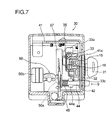
- the metal clamp 33 which constitutes the fixing member, is fixed by means of a screw (not shown) onto a key station 32 which is rotatable by insertion of a key 31, as shown in Fig. 7.
- a clamping portion 33a having an arc-like inner surface is formed on a part of the outer circumference of the metal clamp 33 and is capable of being in sliding contact with an outer circumference of a cylindrical body or tubular body by rotation, whereby the clamping portion 33a is brought into sliding contact with a sliding portion (roller 15) which is disposed on the battery case 10 and having a circular outer circumference (See Fig. 5).
- a magnet 35 is mounted on the metal clamp 33 so that a reed switch (not shown) attached on a substrate (not shown) mounted on a substrate mounting frame 37 is turned on when the magnet 35 approaches the reed switch.
- a reed switch (not shown) attached on a substrate (not shown) mounted on a substrate mounting frame 37 is turned on when the magnet 35 approaches the reed switch.
- the clamping portion 33a of the metal clamp 33 is brought into sliding contact with the sliding portion of the battery case 10 to fix the battery case 10.
- the magnet 35 while maintaining the sliding state, approaches the reed switch to turn the power on.
- a concave-convex portion 33b is formed on the outer circumference of the metal clamp 33 opposite to the clamping portion 33a, as shown in Fig. 6 or Fig. 8, to engage with a spring piece 43 formed by an elastic body that has a shape engaging with its concave portion, thereby allowing clicks in the rotation of the key 31 (so that the key rotates stage by stage) .
- the spring piece 43 is mounted onto a key stay 42 by a screw.
- a pawl portion 33c is formed adjacent to the concave-convex portion 33b. In releasing the fixation of the battery case 10, the pawl portion 33c strikes a projecting piece portion 44a of a stopper pin 44 to inhibit the rotation of the key 31.
- the stopper pin 44 Since the stopper pin 44 is mounted onto the key stay 42 via a spring 45 as shown in Fig. 7, the projecting piece portion 44a of the stopper pin 44 is dislodged from the pawl portion 33c by pressing the stopper pin 44 in the direction of S so as to rotate the key 31 in the releasing direction. Namely, in order to prevent the battery case 10 from falling off by inadvertent rotation of the key 31 in the releasing direction, the battery case 10 is allowed to dislodge by rotating the key 31 while pressing the stopper pin 44.
- the pawl portion 33c is formed in a twisted shape, so that the key 31 can be rotated in a reverse direction, namely in the direction for mounting the battery case 10, without pressing the stopper pin 44.
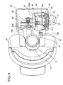
- a pressing member 50 which is a detecting means made of resin, is disposed in contact with a front tip of the stopper pin 44 as seen in the direction of S.
- the pressing member 50 includes a restricting section 50a and a contact section 50b.
- the restricting section 50a is brought into contact with the stopper pin 44.
- the contact section 50b is brought into contact with a protrusion 10c formed on the battery case 10 for being detected and is pressed when the battery case 10 is mounted.
- the pressing member 50 is provided with a spring 51 which is an elastic body for urging the battery case 10 in the direction which resists the battery case 10 from being mounted.
- the pressing member 50 When the battery case 10 is not mounted, the pressing member 50 is pressed towards the battery case 10 by a force of the spring 51 as shown in Fig. 9, so that the restricting section 50a and the stopper pin 44 are in contact and the stopper pin 44 cannot be pressed by the user. Also, when the battery case 10 is mounted as shown in Fig. 10, the pressing member 50 is pressed by the protrusion 10c of the battery case 10, so that the contact between the stopper pin 44 and the restricting section 50a is released and the stopper pin 44 can be operated.
- the force of the spring 51 for urging the pressing member 50 is set to such a degree that the spring 51 does not contract merely under the condition that the battery case 10 is mounted, so that the pressing member 50 can be moved only after the battery case 10 is pressed into a mounted state by a force of the user.
- metal fittings 41 are fixed by being stuck to the standing pipe 2, as shown in Fig. 6 and Fig. 8.
- the above-mentioned key station 32 and the substrate 37 are fixed onto the metal fittings 41 as shown in Fig. 7, and further the key stay 42 for holding the stopper pin 44 and the spring 45 is fixed by the screw 46.
- a tongue piece 41a is provided on the metals fittings 41 and is disposed above the projection 10b of the sliding portion of the battery case 10. As a result, the battery case 10 is prevented from being dislodged upwards by the upward and downward vibration of the battery case 10. Naturally, the lower portion of the battery case is held by the mounting platform 20.
- the other components such as a front wheel, a rear wheel, a handle, a saddle, a pedal, and a chain are the same as those of an ordinary bicycle, and the functions performed by a brake and the like are also the same, so that an explanation thereof will be omitted here.
- the battery case 10 is mounted onto the standing pipe.
- the same explanation will apply also to the case in which the battery case 10 is mounted onto another portion of the main frame such as the main pipe if the battery case 10 is mounted in a vertical direction or in an oblique direction.
- the battery case 10 containing the recharged batteries is mounted on the mounting platform 20 so that the protrusion 10a of the battery case 10 is inserted into the insertion hole 20a of the mounting platform 20, and then the key 31 is rotated while allowing the upper portion of the battery case 10 to be in close contact with the standing pipe 2, whereby the clamping portion 33a of the metal clamp 33 is brought into sliding contact with the sliding portion 15 of the battery case 10 and, by rotating the metal clamp 33 into the state shown in Fig. 6, the upper portion of the battery case 10 is fixed and the switch is turned on. Further, when the metal clamp 33 is rotated by rotating the key 31, the switch is turned off.
Abstract
Description
- The present invention relates to an electrically driven bicycle, and more particularly to an electrically driven bicycle which utilizes a driving power of a motor for assisting a human driving power or which utilizes the driving power of the motor as a main driving power for traveling. Especially, the present invention relates to an electrically driven bicycle in which a shape of a battery case and a configuration of a battery are improved so that a user can ride on and off the bicycle smoothly and can travel in a safe state.
- In a conventional electrically driven bicycle of a certain type, a motor for driving wheels to assist a human driving power for traveling is mounted and a battery as a driving power source for the motor is mounted on the bicycle. As shown generally in Fig. 11, a main frame of the bicycle mainly includes a
head pipe 104 on which ahandlebar 105 is mounted, a standingpipe 102 on which asaddle 106 is mounted, and a main pipe (hidden by abattery case 110 in Fig. 11) bridging thehead pipe 104 and the standingpipe 102, and the like. A structure is generally known in which thebattery case 110 loaded with batteries is disposed on the main pipe, as shown in Fig. 11. Thebattery case 110 may be disposed in the front or in the rear of the standingpipe 102 instead of being disposed on the main pipe. In Fig. 11, thereference numeral 101 represents a driving section incorporating an electric motor, a speed reduction mechanism, a torque sensor, and the like; and thereference numeral 119 represents a frame cover that covers metal fittings provided in the main frame. Thereference numeral 115 represents a cap for covering a charging connector. Thecap 115 prevents intrusion of water and dust. - In the conventional electrically driven bicycle, the battery case is mounted over or under the main pipe, or in the front or in the rear of the standing pipe, as described above. Therefore, a structure is adopted in which a battery pack is prepared, for example, by making five rows each including four batteries connected in series allowing all the batteries to be connected in series, and the battery pack is inserted into the battery case as it is. However, since each of the batteries has a diameter of about 33mm, the height of the stacked batteries will be very high when the number of the stacked batteries is about three or more. Therefore, a problem arises such that there will be a large protuberance formed by the batteries over the main pipe or in front of the standing pipe, making it difficult to ride on or off the bicycle.
- Further, in the case where the batteries are to be disposed in the front or in the rear of the standing pipe, if the battery case is to be disposed on the chain case because of the existence of the chain case, the saddle must be mounted at a higher position, so that it will be very difficult for a less tall person to ride the bicycle because the feet cannot reach the ground so easily. On the other hand, in the case where the batteries are disposed in a space adjacent to the chain case, the batteries are unbalanced, so that the user cannot ride the bicycle in a stable manner and, further, the batteries are not arranged in order, making the wiring complex and increasing the costs.
- Moreover, if such a cap for covering the connector is provided, it may possibly be an obstacle in riding on the bicycle because the clothes or the feet of the user may be caught by the cap and, besides that, the appearance will be deteriorated, although the cap for covering the connector prevents intrusion of water and dust. Also, although the fixing member for fixing the battery to the main frame is provided to interlock with a key, the fixing member can be actuated with the key even if the battery is not fixed to the main frame. Therefore, the user can allow the bicycle to run even if the battery is not firmly fixed to the main frame, so that the battery may possibly fall off while the bicycle is traveling.
- The present invention has been made in view of these circumstances and one object thereof is to provide an electrically driven bicycle with improved facility in riding on and off the bicycle by disposing the batteries separately to surround the main frame in order to provide less protuberance on each side, instead of disposing all the batteries only on one side of the main frame.
- Another object of the present invention is to improve facility in riding on and off the bicycle by allowing the side of the battery case facing away from the main frame (the front or upper side of the battery case) to be shaped like an arc or to have a smaller width.
- Still another object of the present invention is to provide an electrically driven bicycle having a battery configuration that allows the front or upper side of the battery case to have a smaller width.
- Still another object of the present invention is to provide an electrically driven bicycle having a battery configuration with good space utilization efficiency by evading the chain case if the battery case is to be disposed near the standing pipe.
- Still another object of the present invention is to provide an electrically driven bicycle having a battery case without exposing the connector section to outside, thereby eliminating the need for a cap for covering the connector section, reducing the number of components in the bicycle, and providing a good appearance.
- Still another object of the present invention is to provide an electrically driven bicycle in which the battery case can be firmly fixed to the main frame, thereby ensuring a safety of the bicycle.
- Accordingly, the present invention provides an electrically driven bicycle including: a driving section for driving a wheel; a battery for supplying an electric power to the driving section; and a battery case loaded with the battery and mounted onto a main frame of the bicycle, wherein the battery case is formed to have a transversal cross section that includes a recess to cover at least a part of an outer surface of the main frame, and at least a portion of the battery is inserted into an inner space on each side of the recess.
- The present invention will be better understood from the following detailed description of preferred embodiments of the invention, taken in conjunction with the accompanying drawings, in which:
- Fig. 1 is a side view of an electrically driven bicycle according to one embodiment of the present invention;
- Fig. 2 is a view showing a transversal cross section of a battery case and a standing pipe of the electrically driven bicycle of Fig. 1;
- Fig. 3 is a view showing a vertical cross section of the battery case of the electrically driven bicycle of Fig. 1;
- Fig. 4 is a view showing a vertical cross section of a charging connector section in the electrically driven bicycle of Fig. 1;
- Fig. 5 is a cross-sectional view cut along the line A-A of Fig. 4;
- Fig. 6 is a cross-sectional view showing a fixed state of an upper portion of the battery case by means of a fixing means;
- Fig. 7 is a cross-sectional view cut along the line A-A of Fig. 6;
- Fig. 8 is a cross-sectional view showing a non-fixed state of the upper portion of the battery case by means of a fixing means;
- Fig. 9 is a cross-sectional view cut along the line B-B of Fig. 8;
- Fig. 10 is a cross-sectional view cut along the line B-B of Fig. 6; and
- Fig. 11 is a side view of a conventional electrically driven bicycle according to one example.
-
- The present invention provides an electrically driven bicycle including: a driving section for driving a wheel; a battery for supplying an electric power to the driving section; and a battery case loaded with the battery and mounted onto a main frame of the bicycle, wherein the battery case is formed to have a transversal cross section that includes a recess to cover at least a part of an outer surface of the main frame, and at least a portion of the battery is inserted into an inner space on each side of the recess.
- Here, the main frame of the bicycle refers to a principal component of a bicycle frame that constitutes the bicycle and includes a head pipe (head tube) on which a handlebar is to be mounted, a standing pipe (seat tube) on which a saddle (seat) is to be mounted, a main pipe (down tube) that bridges the head pipe and the standing pipe, and the like.
- With this structure, the battery case is prevented from protruding only to one side of the main frame, thereby providing a compact shape and greatly improving the facility in riding on and off the bicycle.
- The battery case that covers the main frame has an outline of the transversal cross section such that a central portion of a perimeter opposite to the recess has an arc-like shape or the width of the central portion is smaller than the width of the perimeter of the recess. Accordingly, the width of the front or upper side of the protrusion from the main frame will be smaller, thereby greatly improving the facility in riding on and off the bicycle.
- The plurality of batteries to be inserted into the battery case are preferably formed into a battery assembly. Namely, the battery assembly is made of a first battery pack having n batteries (where n is an integer of two or more) arranged in a line and wrapped in series connection and two second battery packs each having n batteries arranged in a plurality of lines and wrapped in series connection.
- Preferably, the battery case includes a protrusion formed opposite to the recess; the first battery pack is inserted into an inner space of the protrusion; and each of the two second battery packs is respectively inserted into the inner space on each side of the recess in such a manner that the two second battery packs are closer to each other in a direction towards the first battery pack.
- Since the two second battery packs are inserted as described above so that the two second battery packs are closer to each other on the first battery pack side, the front or upper side of the battery case facing away from the main frame can be advantageously formed to have an arc-like shape or to have a smaller width.
- Preferably, the electrically driven bicycle of the present invention is constructed in such a manner that the main frame includes a standing pipe and a main pipe; the standing pipe extends obliquely in a downward and forward direction from the saddle; the main pipe is connected to the standing pipe and extends obliquely in an upward and forward direction; the electrically driven bicycle further includes a chain case and a mounting platform; the chain case extends toward a rear wheel from a connecting part of the standing pipe and the main pipe; the mounting platform is disposed at the connecting part and serves to mount the battery case on the standing pipe by mounting a lower end of the battery case thereon; the battery case is provided with a narrow portion and a wide portion; the narrow portion is disposed at the lower end of the battery case and formed to have a width smaller than that of an upper portion of the battery case in a right-and-left direction so as not to interfere with the chain case; the narrow portion is provided with an output terminal for the batteries; the wide portion is disposed at the upper portion of the battery case and extends above the chain case; and the batteries are inserted into an inner space of the wide portion so that the batteries are substantially symmetrical with respect to a central plane formed by a center line of the standing pipe and a center line of the main pipe.
- By providing the above construction, the batteries are substantially symmetrical with respect to the central plane in the right-and-left direction, thereby improving a stability of the bicycle. Further, the height of the battery case from a bottom of the bicycle can be made smaller by efficiently arranging other electronic components, such as an output terminal and a connector, adjacent to the chain case.
- Preferably, the electrically driven bicycle of the present invention is constructed in such a manner that the batteries are rechargeable; the battery case includes a charging connector section for charging the batteries; the connector section is located at a portion of the battery case nearer to the main frame; and the battery case is mounted onto the main frame in such a manner that the connector section is hidden by the main frame.
- By providing this construction, since the charging connector section is hidden by the main frame, intrusion of water and dust can be easily prevented, whereby a need for providing a cap is eliminated, thus reducing the number of components in the bicycle.
- Preferably, an elastic sheet is disposed at a contacting part of the battery case and the main frame so as to fix the battery case firmly onto the main frame and to prevent wobbling of the battery case. Preferably, the elastic sheet is disposed above the charging connector section and between the battery case and the standing pipe in the case where the battery case is mounted near the standing pipe of the main frame, thereby shutting off the rain water and the like coming down along the standing pipe.
- Preferably, the battery case has a structure such that the side portions of the battery case are bent towards the main frame so that the battery case covers the charging connector section, thereby further protecting the charging connector section from the rain water and the like. Specifically, it is preferable that the battery case is formed to have a substantially U-shaped transversal cross section and is mounted to cover the main frame, and the charging connector section is disposed at a bottom of the U-shaped portion.
- Preferably, the electrically driven bicycle of the present invention further includes a mount detecting means and a fixing means; the mount detecting means detects that the battery case is mounted to a predetermined position of the main frame; the fixing means fixes the battery case to the main frame, whereby the fixing means fixes the battery case to the main frame only when the mount detecting means detects that the battery case is mounted to the main frame.
- In other words, in the case where the battery case is to be mounted on the main frame, the detecting means does not detect that the battery case is mounted and the fixing means cannot fix the battery case onto the main frame until the battery case is firmly mounted to the main frame. When the battery case is firmly mounted to the main frame, the fixing means can fix the battery case onto the main frame.
- Further, the detecting means may include an elastic body (an urging member) for urging the battery case in the non-mounting direction (i.e. in a direction that resists the battery case from being mounted to the main frame). The elastic body preferably has an elastic force larger than the weight of the battery case.
- By providing this construction, the fixing means cannot fix the battery case onto the main frame merely under a condition that the battery case is mounted onto the main frame. It is only after the battery case is pressed by a force of the user to contract the elastic body in the mounting direction that the fixing means is actuated to fix the battery case onto the main frame.
- Preferably, the fixing means includes a lock that fixes/releases the battery case to/from the main frame and is interlocked with a power switch, whereby the power switch is turned on when the battery case is fixed to the main frame by the lock.
- By providing this construction, an electric power circuit is not energized if the battery case is not firmly mounted to the main frame, and it is only after the battery case is fixed to the main frame by the fixing means that the power switch is turned on, thereby ensuring a safety of the bicycle.
- Preferably, the battery case is disposed in a neighborhood including at least an outer surface of the standing pipe of the main frame at a front wheel side, and the fixing means includes a lock disposed at a rear wheel side of the standing pipe and releasably fixing an upper end of the battery case to the standing pipe.
- By providing this construction, the battery case will not be an obstacle for riding on and off the bicycle, and the battery case can be fixed onto the standing pipe in an embracing manner, so that the battery case can be firmly fixed onto the standing pipe.
- An electrically driven bicycle according to the present invention is now detailed with reference to the attached drawings.
- Referring to Fig. 1 which illustrates a side view of an embodiment, the electrically driven bicycle of the present invention includes a driving section 1 for driving a wheel, a battery for supplying an electric power to the driving section 1, and a
battery case 10 for housing the battery. Thebattery case 10 is mounted near a standingpipe 2 which is a component of a main frame. Referring to Fig. 2, thebattery case 10 is formed to have a transversal cross section that includes arecess 10c to cover at least a part of an outer perimeter (outer surface) of the standingpipe 2. - As shown in Fig. 2, the
battery case 10 is formed to have a U-shaped cross section by providing therecess 10c which covers a front wheel side and lateral sides of the standingpipe 2. In other words, thebattery case 10 is disposed to cover not only the front or rear part of the standingpipe 2 but also the lateral sides of the standingpipe 2. Further, in the embodiment shown in Fig. 2, thebattery case 10 is formed so that the front part thereof has a width E smaller than the width D of thebattery case 10 at the standingpipe 2 side. Thebattery case 10 includes arear case 18a and afront case 18b that are formed, for example, by plastic molding. Therear case 18a and thefront case 18b are formed into one case by an engagement ofpawls 18c. - As shown by a vertical cross section in Fig. 3, the
battery case 10 houses a battery assembly including afirst battery pack 12a having fourbatteries 12 arranged in a line and wrapped in series connection into a packed body and two second battery packs 12b each having eight batteries arranged in two lines (each line containing four batteries) and wrapped in series connection into two packed bodies. As shown in Fig. 2, thefirst battery pack 12a is inserted into an inner space of a top portion which is a protrusion formed opposite to the front side of the standingpipe 2, namely, opposite to therecess 10c, and thesecond packs 12b are inserted in the direction from the lateral sides of the standing pipe 2 (i.e. the inner spaces on both sides of therecess 10c) towards thefirst pack 12a. - These twenty
batteries 12 are connected together in series. In the embodiment shown in Fig. 2, the twosecond packs 12b are respectively inserted into the inner spaces on both sides of the standingpipe 2 in such a manner that the two second battery packs 12b are closer to each other on thefirst pack 12a side, i.e. so that the cross sections of the second battery packs form a shape like a character "" above-mentioned
pawls 18c for engaging therear case 18a and thefront case 18b are formed at a position approximately in the middle of a side surface of eachsecond battery pack 12b. - A
protrusion 10a is provided at a bottom of thebattery case 10. Theprotrusion 10a can be inserted into aninsertion hole 20a of a mountingplatform 20 fixed by welding or the like to the standingpipe 2 and themain pipe 3 at a connecting part of thepipes battery case 10 is formed to have a smaller width in order to evade the chain case 7 (See F of Fig. 3), and an upper portion of thebattery case 10 above thechain case 7 is formed to have a larger width (See G of Fig. 3) . Thebatteries 12 are inserted into the upper and wider portion of thebattery case 10 so that the batteries are approximately symmetrical in the right-and-left direction with respect to a central plane (the plane formed by the center line of the standingpipe 2 and the center line of the main pipe 3) . Further, electric components such as a chargingconnector 11, afuse 13, and anoutput terminal 14 are disposed in the lower and narrower portion of thebattery case 10. Therefore, the upper and wider portion of thebattery case 10 can be used exclusively as a space for thebatteries 12, so that thebatteries 12 can be arranged efficiently in thebattery case 10. - The lower end of the
battery case 10 as shown above is fixed near the standingpipe 2 by insertion of itsprotrusion 10a into theinsertion hole 20a of the mountingplatform 20, and the upper portion of thebattery case 10 is clamped, in interlocking relationship with the rotation of the key that switches the output of the battery on and off, by means ofmetal clamp 33 of akey box 30 as a lock that is attached to the standingpipe 2. The output terminal of thebattery case 10 will be connected to a connection pin of aterminal platform 22 provided on the mountingplatform 20 when thebattery case 10 is mounted on the mountingplatform 20. Also, anelastic sheet 17 is stuck by adhesion onto an inner surface of therecess 10c of thebattery case 10 so that thebattery case 10 is firmly fixed onto the standingpipe 2 without causing a wobble. The periphery of the mountingplatform 20 is covered by aframe cover 28 to protect the mountingplatform 20 and to maintain good appearance. - The other components such as a front wheel, a rear wheel, a handlebar, a saddle, a pedal, and a chain are the same as those of an ordinary bicycle, and the functions performed by a brake and the like are also the same, so that an explanation thereof will be omitted here. In the previous example, the
battery case 10 is disposed in the front and on the lateral sides of the standingpipe 2 so as to cover the standingpipe 2. The same explanation will apply also to the case in which thebattery case 10 is mounted near another portion of the main frame, such as the main pipe. The central portion of thebattery case 10 disposed at the front side opposite to the recess and facing away from the main frame may be formed to have a continuous arc-like shape from the lateral sides instead of being formed to have a narrow projection in its transversal cross section. - As described above, the
battery case 10 in the electrically driven bicycle of the present invention includes therecess 10c that covers the main frame. Accordingly, the thickness or the height of thebattery case 10 protruding forward or upward from the main frame can be made smaller than in conventional bicycles, so that thebattery case 10 will not be an obstacle in riding on and off the bicycle. Also, even if thebattery case 10 extends in the lateral direction of the standingpipe 2 or the main pipe, the width of thebattery case 10 is smaller than the distance between the pedals, so that thebattery case 10 will not be an obstacle in stepping the pedals or in riding on and off the bicycle, thereby providing an electrically driven bicycle with great facility in riding on and off the bicycle. The facility in riding on and off the bicycle will be further improved in the case where the top portion of the protrusion (the front portion opposite to the recess) of thebattery case 10 is formed to have an arc-like shape or to have a smaller width in its transversal cross section. - The plurality of
batteries 12 to be inserted into thebattery case 10 having the above structure cannot be inserted together as a bundle. However, the width of thebattery case 10 at its front or upper portion can be made smaller than the width of thebattery case 10 at its lateral sides by dividing thebatteries 12 into afirst pack 12a having a plurality ofbatteries 12 arranged in a line and twosecond packs 12b each having a plurality of batteries arranged in two lines and by inserting each of the twosecond packs 12b respectively into an inner space on each side of therecess 10c and inserting thefirst pack 12a into the protrusion opposite to therecess 10c. Therefore, thebattery case 10 can be formed into a smooth arc-like shape without a square shoulder portion (See R portion in Fig. 2). - In other words, if the two
second packs 12b of batteries are inserted parallel to each other, their shoulder portions will protrude greatly like a square, so that the width of the battery case at its front or upper portion will be wider. However, by inserting the twosecond packs 12b ofbatteries 12 obliquely so that they are not parallel to each other, the width of thebattery case 10 at its front or upper portion can be made smaller, as described before. Further, since the twosecond packs 12b ofbatteries 12 disposed on the lateral sides are obliquely arranged so that they are closer to each other at the front or upper portion thereof, a space for engagement of thepawls 18c can be ensured by dividing thebattery case 10 into two portions and providing the engagement portions on the lateral sides of the twosecond packs 12b. As a result, thebattery case 10 can be formed to be compact and with a narrow width at its front or upper portion. - Further, by allowing the rear or bottom portion of the
battery case 10 to have a narrower width, thechain case 7 can be evaded and, moreover, by mounting the electric components such as an output terminal and a connector in the narrower portion, thebatteries 12 can be arranged in the wider portion above thechain case 7 so that thebatteries 12 are approximately in symmetry in the right-and-left direction with respect to the central plane, thereby providing abattery case 10 which is compact and stable. - The charging
connector 11 for charging therechargeable batteries 12 is disposed at the standingpipe 2 side of thebattery case 10, as shown in Fig. 4 which illustrates a vertical cross section of that portion. Further, thebattery case 10 is mounted so that the chargingconnector 11 is hidden by the standingpipe 2, as shown in Fig. 5 which illustrates a cross section cut along the line A-A of Fig. 4. - A
protrusion 10a is disposed at the bottom of thebattery case 10. Theprotrusion 10a engages with aninsertion hole 20a provided in the mountingplatform 20 and is fixed thereto by atongue piece 21 of the mountingplatform 20 for preventing thebattery case 10 from falling forward. Also, in this example, anoutput terminal 14 is disposed to be in contact with aconnection pin 23 provided on the mountingplatform 20, so that the output from thebatteries 12 can be taken out simply by mounting thebattery case 10 onto the mountingplatform 20. - An upper portion of the
battery case 10 is fixed by being pulled towards the standingpipe 2 by means of akey box 30, as shown in Fig. 1. Therefore, the upper portion of thebattery case 10 can be easily dislodged by releasing the fixation performed by thekey box 30 and pulling the upper portion of thebattery case 10 upward while allowing the battery case to lean a little forward. Conversely in mounting thebattery case 10, theprotrusion 10a at the bottom of thebattery case 10 is inserted into theinsertion hole 20a of the mountingplatform 20 by mounting thebattery case 10 onto the mountingplatform 20 while allowing thebattery case 20 to lean a little forward, and thebattery case 10 is mounted in place by allowing the upper portion of thebattery case 10 to approach toward the standingpipe 2, whereby thebattery case 10 can be easily fixed by means of thekey box 30. - In the present invention, the charging
connector 11 is disposed at a position at the bottom of thebattery case 10 and at a center of the side which is in contact with the standingpipe 2. The rechargeable batteries can be charged, for example, by inserting a plug, which is provided in a charger (not shown), into the chargingconnector 11. Since the chargingconnector 11 is provided on the standingpipe 2 side of thebattery case 10 in the present invention, thebatteries 12 cannot be charged while thebattery case 10 is mounted on the main frame. Thebatteries 12 are charged by dislodging thebattery case 10 and inserting the plug of the charger. Meanwhile, an opening of the chargingconnector 11 is blocked by the standingpipe 2, so that the chargingconnector 11 is not visible from outside at all and is mounted directly in contact with the standingpipe 2 without a cap. - In this example, an
elastic sheet 17 is disposed between thebattery case 10 and the standingpipe 2. Theelastic sheet 17 is, for example, made of an expanded urethane foam and is preferably disposed because theelastic sheet 17 can fix thebattery case 10 to the standingpipe 2 firmly and can prevent wobbling of thebattery case 10. In the example shown in Fig. 4 and Fig. 5, theelastic sheet 17 is disposed at a position above theconnector 11. By providing theelastic sheet 17 at a position above theconnector 11, theelastic sheet 17 will not be an obstacle in charging the batteries even if theelastic sheet 17 is kept fixed onto thebattery case 10. Moreover, the rain water running down from above can be prevented from immersing into theconnector 11. Alternatively, however, if theelastic sheet 17 is stuck onto the standingpipe 2, theelastic sheet 17 can lie over theconnector 11 as well, thereby further preventing the wobbling of thebattery case 10 and the immersion of water into theconnector 11. - In the electrically driven bicycle of the present invention, the upper portion of the
battery case 10 is fixed by means of a fixing member (metal clamp 33) of thekey box 30 which is mounted on the standingpipe 2, as shown in Fig. 6. - In the
key box 30, themetal clamp 33, which constitutes the fixing member, is fixed by means of a screw (not shown) onto akey station 32 which is rotatable by insertion of a key 31, as shown in Fig. 7. A clampingportion 33a having an arc-like inner surface is formed on a part of the outer circumference of themetal clamp 33 and is capable of being in sliding contact with an outer circumference of a cylindrical body or tubular body by rotation, whereby the clampingportion 33a is brought into sliding contact with a sliding portion (roller 15) which is disposed on thebattery case 10 and having a circular outer circumference (See Fig. 5). Amagnet 35 is mounted on themetal clamp 33 so that a reed switch (not shown) attached on a substrate (not shown) mounted on asubstrate mounting frame 37 is turned on when themagnet 35 approaches the reed switch. In other words, by a predetermined amount (one stage) of rotation of the key 31, the clampingportion 33a of themetal clamp 33 is brought into sliding contact with the sliding portion of thebattery case 10 to fix thebattery case 10. By one further stage of rotation, themagnet 35, while maintaining the sliding state, approaches the reed switch to turn the power on. - A concave-
convex portion 33b is formed on the outer circumference of themetal clamp 33 opposite to the clampingportion 33a, as shown in Fig. 6 or Fig. 8, to engage with aspring piece 43 formed by an elastic body that has a shape engaging with its concave portion, thereby allowing clicks in the rotation of the key 31 (so that the key rotates stage by stage) . Thespring piece 43 is mounted onto akey stay 42 by a screw. Further, apawl portion 33c is formed adjacent to the concave-convex portion 33b. In releasing the fixation of thebattery case 10, thepawl portion 33c strikes a projectingpiece portion 44a of astopper pin 44 to inhibit the rotation of the key 31. - Since the
stopper pin 44 is mounted onto thekey stay 42 via aspring 45 as shown in Fig. 7, the projectingpiece portion 44a of thestopper pin 44 is dislodged from thepawl portion 33c by pressing thestopper pin 44 in the direction of S so as to rotate the key 31 in the releasing direction. Namely, in order to prevent thebattery case 10 from falling off by inadvertent rotation of the key 31 in the releasing direction, thebattery case 10 is allowed to dislodge by rotating the key 31 while pressing thestopper pin 44. Thepawl portion 33c is formed in a twisted shape, so that the key 31 can be rotated in a reverse direction, namely in the direction for mounting thebattery case 10, without pressing thestopper pin 44. - A pressing
member 50, which is a detecting means made of resin, is disposed in contact with a front tip of thestopper pin 44 as seen in the direction of S. The pressingmember 50 includes a restrictingsection 50a and acontact section 50b. The restrictingsection 50a is brought into contact with thestopper pin 44. Thecontact section 50b is brought into contact with aprotrusion 10c formed on thebattery case 10 for being detected and is pressed when thebattery case 10 is mounted. Further, the pressingmember 50 is provided with aspring 51 which is an elastic body for urging thebattery case 10 in the direction which resists thebattery case 10 from being mounted. - When the
battery case 10 is not mounted, the pressingmember 50 is pressed towards thebattery case 10 by a force of thespring 51 as shown in Fig. 9, so that the restrictingsection 50a and thestopper pin 44 are in contact and thestopper pin 44 cannot be pressed by the user. Also, when thebattery case 10 is mounted as shown in Fig. 10, the pressingmember 50 is pressed by theprotrusion 10c of thebattery case 10, so that the contact between thestopper pin 44 and the restrictingsection 50a is released and thestopper pin 44 can be operated. The force of thespring 51 for urging the pressingmember 50 is set to such a degree that thespring 51 does not contract merely under the condition that thebattery case 10 is mounted, so that the pressingmember 50 can be moved only after thebattery case 10 is pressed into a mounted state by a force of the user. - In the
key box 30,metal fittings 41 are fixed by being stuck to the standingpipe 2, as shown in Fig. 6 and Fig. 8. The above-mentionedkey station 32 and thesubstrate 37 are fixed onto themetal fittings 41 as shown in Fig. 7, and further thekey stay 42 for holding thestopper pin 44 and thespring 45 is fixed by the screw 46. Atongue piece 41a is provided on themetals fittings 41 and is disposed above theprojection 10b of the sliding portion of thebattery case 10. As a result, thebattery case 10 is prevented from being dislodged upwards by the upward and downward vibration of thebattery case 10. Naturally, the lower portion of the battery case is held by the mountingplatform 20. - The other components such as a front wheel, a rear wheel, a handle, a saddle, a pedal, and a chain are the same as those of an ordinary bicycle, and the functions performed by a brake and the like are also the same, so that an explanation thereof will be omitted here. In the previous example, the
battery case 10 is mounted onto the standing pipe. The same explanation will apply also to the case in which thebattery case 10 is mounted onto another portion of the main frame such as the main pipe if thebattery case 10 is mounted in a vertical direction or in an oblique direction. - Next, with reference to Figs. 6, 10, 8, and 9, an explanation will be given on the operations of attaching/detaching the
battery case 10 and turning the switch on/off by operating the key 31 of thekey box 30. Referring to Figs. 8 and 9, the upper portion of thebattery case 10 is not fixed while the clampingportion 33a of themetal clamp 33 is not in sliding contact with the sliding portion of thebattery case 10, and thebattery case 10 can be dislodged by tilting the upper portion of thebattery case 10 forward and pulling it out. Here, thebattery case 10 cannot be brought from the fixed state into this released state unless thestopper pin 44 is pressed as described before. - On the other hand, the
battery case 10 containing the recharged batteries is mounted on the mountingplatform 20 so that theprotrusion 10a of thebattery case 10 is inserted into theinsertion hole 20a of the mountingplatform 20, and then the key 31 is rotated while allowing the upper portion of thebattery case 10 to be in close contact with the standingpipe 2, whereby the clampingportion 33a of themetal clamp 33 is brought into sliding contact with the slidingportion 15 of thebattery case 10 and, by rotating themetal clamp 33 into the state shown in Fig. 6, the upper portion of thebattery case 10 is fixed and the switch is turned on. Further, when themetal clamp 33 is rotated by rotating the key 31, the switch is turned off. - Next, an explanation of the operation for mounting the
battery case 10 will be given. In the case where thebattery case 10 is dislodged for charging or the like, the position of the key 31 is such that the key 31 has been rotated clockwise, as shown in Fig. 8. This state prevents the user from pressing thestopper pin 44 because thestopper pin 44 and the restrictingsection 50a of the pressingmember 50 are in contact, as shown in Fig. 9. When thebattery case 10 is mounted and thebattery case 10 is pressed against the force of thespring 51 by the user, thecontact portion 50b is pressed by theprotrusion 10c and the pressingmember 50 is pressed upwards as a whole in the Figure, releasing the contact between the restrictingsection 50a and thestopper pin 44, whereby thestopper pin 44 can be pressed by the user. By this construction, the key 31 cannot be rotated and an electric power cannot be supplied from the batteries unless thebattery case 10 is firmly mounted. - Although the present invention has fully been described by way of example with reference to the accompanying drawings, it is to be understood that various changes and modifications will be apparent to those skilled in the art. Therefore, unless otherwise such changes and modifications depart from the scope of the invention, they should be construed as being included therein.
Claims (15)
- An electrically driven bicycle comprising:a driving section for driving a wheel;a battery for supplying an electric power to the driving section; anda battery case loaded with the battery and mounted onto a main frame of the bicycle,wherein the battery case is formed to have a transversal cross section that includes a recess to cover at least a part of an outer surface of the main frame, and at least a portion of the battery is inserted into an inner space on each side of the recess.
- The electrically driven bicycle of claim 1, wherein a battery assembly is formed to include a first battery pack having a plurality of batteries arranged in a line and wrapped in series connection and two second battery packs each having a plurality of batteries arranged in a plurality of lines and wrapped in series connection, the battery case including a protrusion formed opposite to the recess, the first battery pack being inserted into an inner space of the protrusion, and each of the two second battery packs being respectively inserted into the inner space on each side of the recess in such a manner that the two second battery packs are closer to each other in a direction towards the first battery pack.
- The electrically driven bicycle of claim 1, wherein the main frame comprises a standing pipe and a main pipe, the standing pipe extending obliquely in a downward and forward direction from the saddle, the main pipe being connected to the standing pipe and extending obliquely in an upward and forward direction, the electrically driven bicycle further comprising a chain case and a mounting platform, the chain case extending toward a rear wheel from a connecting part of the standing pipe and the main pipe, the mounting platform being disposed at the connecting part and serving to mount the battery case on the standing pipe by mounting a lower end of the battery case thereon, the battery case being provided with a narrow portion and a wide portion, the narrow portion being disposed at the lower end of the battery case and formed to have a width smaller than that of an upper portion of the battery case in a right-and-left direction so as not to interfere with the chain case, the narrow portion being provided with an output terminal for the batteries, the wide portion being disposed at the upper portion of the battery case and extending above the chain case, the batteries being inserted into an inner space of the wide portion so that the batteries are substantially symmetrical with respect to a central plane formed by a center line of the standing pipe and a center line of the main pipe.
- The electrically driven bicycle of claim 1, wherein the battery is rechargeable and the battery case includes a charging connector section for charging the battery, the connector section being located at a portion of the battery case nearer to the main frame, the battery case being mounted onto the main frame in such a manner that the connector section is hidden by the main frame.
- The electrically driven bicycle of claim 4, wherein the battery case is mounted in contact with the main frame and an elastic sheet is disposed at a contacting part of the battery case and the main frame.
- The eiectrically driven bicycle of claim 5, wherein the battery case is mounted onto the standing pipe of the main frame and the elastic sheet is disposed above the connector section of the battery case and at the contacting part of the battery case and the standing pipe.
- The electrically driven bicycle of claim 4, wherein a side surface of the battery case is formed to have a shape which covers a side portion of the outer surface of the main frame.
- The electrically driven bicycle of claim 7, wherein the battery case includes a U-shaped portion having a substantially U-shaped transversal cross section and the connector section is disposed at a bottom of the U-shaped portion.
- The electrically driven bicycle of claim 1, further comprising a mount detecting means and a fixing means, the mount detecting means detecting that the battery case is mounted to a predetermined position of the main frame, the fixing means fixing the battery case to the main frame, whereby the fixing means fixes the battery case to the main frame only when the mount detecting means detects that the battery case is mounted to the main frame.
- The electrically driven bicycle of claim 9 wherein the mount detecting means includes an urging member for urging the battery case in a direction that resists the battery case from being mounted.
- The electrically driven bicycle of claim 9 wherein the fixing means comprises a lock that fixes/releases the battery case to/from the main frame and is interlocked with a power switch, whereby the power switch is turned on when the battery case is fixed to the main frame by the lock.
- The electrically driven bicycle of claim 9 wherein the battery case is disposed in a neighbourhood including at least an outer surface of the standing pipe of the main frame at a front wheel side, and the fixing means comprises a lock disposed at a rear wheel side of the standing pipe and releasably fixing an upper end of the battery case to the standing pipe.
- A battery case for fitting to a bicycle frame characterised in that the case is generally U-shaped in cross section to provide a recess therein to receive the frame and enable the case to be fitted thereto, the case having lateral portions on either side of the recess adapted to receive at least a portion of the battery therein.
- A battery case as claimed in claim 13 characterised in that the case includes an intermediate portion between the lateral portions which is adapted to receive a portion of the battery therein.
- A battery case as claimed in claim 13 or claim 14 characterised in that the lateral portions of the case diverge outwardly relative to the intermediate portion so that the width of the case remote from the intermediate portion is wider than the intermediate portion.
Applications Claiming Priority (12)
| Application Number | Priority Date | Filing Date | Title |
|---|---|---|---|
| JP250384/97 | 1997-09-16 | ||
| JP250386/97 | 1997-09-16 | ||
| JP25038497 | 1997-09-16 | ||
| JP25038597A JP3475054B2 (en) | 1997-09-16 | 1997-09-16 | Electric bicycle |
| JP250385/97 | 1997-09-16 | ||
| JP25038697 | 1997-09-16 | ||
| JP25038597 | 1997-09-16 | ||
| JP25038497A JP3363754B2 (en) | 1997-09-16 | 1997-09-16 | Electric bicycle |
| JP25038697A JP3470941B2 (en) | 1997-09-16 | 1997-09-16 | Electric bicycle |
| JP1625398 | 1998-01-28 | ||
| JP01625398A JP3495585B2 (en) | 1998-01-28 | 1998-01-28 | Electric bicycle |
| JP16253/98 | 1998-01-28 |
Publications (2)
| Publication Number | Publication Date |
|---|---|
| EP0908380A2 true EP0908380A2 (en) | 1999-04-14 |
| EP0908380A3 EP0908380A3 (en) | 2000-08-09 |
Family
ID=27456538
Family Applications (1)
| Application Number | Title | Priority Date | Filing Date |
|---|---|---|---|
| EP98307440A Withdrawn EP0908380A3 (en) | 1997-09-16 | 1998-09-15 | Electrically driven bicycle |
Country Status (3)
| Country | Link |
|---|---|
| US (1) | US6148944A (en) |
| EP (1) | EP0908380A3 (en) |
| CA (1) | CA2246590A1 (en) |
Cited By (4)
| Publication number | Priority date | Publication date | Assignee | Title |
|---|---|---|---|---|
| EP2955046A1 (en) * | 2014-06-11 | 2015-12-16 | Robert Bosch Gmbh | Electrically operated vehicle, in particular electric bicycle, with improved battery assembly |
| GB2573747A (en) * | 2018-05-08 | 2019-11-20 | Ford Global Tech Llc | A transport device with chassis mounted battery |
| CN112141250A (en) * | 1999-04-21 | 2020-12-29 | 吴正德 | Electric bicycle |
| IT202000000511A1 (en) * | 2020-01-14 | 2021-07-14 | C B T Italia Eredi Di Tardivo Giovanni Snc | Frame assembly for a pedal assisted cycle including an improved battery pack and battery pack |
Families Citing this family (31)
| Publication number | Priority date | Publication date | Assignee | Title |
|---|---|---|---|---|
| US6415881B1 (en) * | 2000-12-13 | 2002-07-09 | Shui-Te Tsai | Retaining device of scooter battery set |
| EP1441401A1 (en) * | 2003-01-25 | 2004-07-28 | Pihsiang Machinery MFG. Co., Ltd. | Battery module structure of electrical vehicle |
| US7168514B2 (en) * | 2003-06-27 | 2007-01-30 | Gregory James Newell | Materials handling device and system |
| US7243937B2 (en) * | 2005-02-18 | 2007-07-17 | Shimano, Inc. | Bicycle control apparatus |
| US20060186158A1 (en) * | 2005-02-18 | 2006-08-24 | Shimano, Inc. | Water resisting apparatus for a bicycle electrical component |
| US7267352B2 (en) * | 2005-02-18 | 2007-09-11 | Shimano, Inc. | Apparatus for mounting an electrical component to a bicycle |
| JP4065286B2 (en) * | 2005-08-09 | 2008-03-19 | 株式会社シマノ | Bicycle electric derailleur |
| DE102010000740A1 (en) * | 2010-01-08 | 2011-07-14 | Robert Bosch GmbH, 70469 | Electric bicycle has frame with multiple frame elements and battery pack with battery parts, where battery pack is detachably arranged at outer side of frame elements |
| DE102010005222A1 (en) | 2010-01-21 | 2011-07-28 | Schaeffler Technologies GmbH & Co. KG, 91074 | Power supply unit for use in car, has frame held into stared confinement that defines holding area by multiple elastic connections, and exhibiting defined spacing to stared confinement when supply unit is supported in holding area |
| JP5783400B2 (en) * | 2010-05-20 | 2015-09-24 | 有限会社Tsdesign | bicycle |
| US8469381B2 (en) * | 2010-08-26 | 2013-06-25 | Cycling Sports Group, Inc. | Bicycle |
| US8893837B2 (en) * | 2011-06-14 | 2014-11-25 | Samsung Sdi Co., Ltd. | Battery pack storing device and electric vehicle including the same |
| DE102011055719B4 (en) * | 2011-11-25 | 2013-10-31 | Günter Lang | Energy storage device for attachment to a bicycle frame |
| JP5999914B2 (en) * | 2012-02-09 | 2016-09-28 | 本田技研工業株式会社 | Electric vehicle power supply |
| US9085342B2 (en) * | 2012-03-03 | 2015-07-21 | Dr. Nathan Jauvtis Engineering | Power assisted vehicle |
| US9434445B1 (en) * | 2012-03-03 | 2016-09-06 | Dr. Nathan Jauvtis Engineering | Electronic bicycle |
| KR101366557B1 (en) * | 2012-09-19 | 2014-02-26 | 주식회사 만도 | Apparatus for driving electric bicycle |
| USD774971S1 (en) * | 2014-10-31 | 2016-12-27 | Piaggio & C. S.P.A. | Electric bicycle |
| DE102014226828B4 (en) * | 2014-12-22 | 2019-02-07 | Biketec Ag | Bicycle frame, electric bicycle and energy storage |
| DE102015210234B4 (en) * | 2015-06-03 | 2023-06-15 | Vitesco Technologies Germany Gmbh | Housing for a cell block for an electrically powered vehicle |
| US10518841B2 (en) | 2015-06-26 | 2019-12-31 | Specialized Bicycle Components, Inc. | Ebike battery mount |
| TWD181925S (en) * | 2015-10-10 | 2017-03-21 | 杭州雲造科技有限公司 | electric power bicycle |
| US10183591B2 (en) | 2015-12-18 | 2019-01-22 | Darfon Electronics (Suzhou) Co., Ltd. | Electric bicycle and battery lift mechanism and battery carrying device thereof |
| USD811275S1 (en) * | 2016-04-06 | 2018-02-27 | Matthew Hendey | Combination frame for an electric bicycle and housing for a motor and batteries |
| USD828232S1 (en) * | 2016-11-14 | 2018-09-11 | Olimpia Kerekpar Kft | Cargo bicycle frame |
| JP6731368B2 (en) * | 2017-03-17 | 2020-07-29 | 株式会社シマノ | Bicycle battery unit |
| WO2019028570A1 (en) * | 2017-08-10 | 2019-02-14 | 付萌华 | Frame tube for use with electric bicycle |
| TWM562237U (en) * | 2018-03-01 | 2018-06-21 | Kwang Yang Motor Co | Electric vehicle battery structure |
| CN109004125A (en) * | 2018-07-16 | 2018-12-14 | 项灿 | Tube hidden type battery |
| TW202110699A (en) | 2019-07-16 | 2021-03-16 | 美商哈雷機車公司 | Electric bicycle |
| USD929268S1 (en) | 2019-08-20 | 2021-08-31 | Serial 1 Cycle Company, Llc | Bicycle |
Family Cites Families (12)
| Publication number | Priority date | Publication date | Assignee | Title |
|---|---|---|---|---|
| FR2497734A1 (en) * | 1980-10-15 | 1982-07-16 | Peugeot Cycles | TWO WHEEL VEHICLE WITH ELECTRIC PROPULSION |
| US5197559A (en) * | 1990-09-04 | 1993-03-30 | Fortress Life-Style, Inc. | Foldable wheelchair with optional power or manual drive |
| JPH04358989A (en) * | 1991-06-05 | 1992-12-11 | Yamaha Motor Co Ltd | Change gear of bicycle |
| ES2112347T3 (en) * | 1992-03-19 | 1998-04-01 | Sanyo Electric Co | BICYCLE DRIVEN BY A MOTOR AND PEDALS. |
| TW467091U (en) * | 1994-03-29 | 2001-12-01 | Sanyo Electric Co | Electric bicycle |
| JPH07329858A (en) * | 1994-06-11 | 1995-12-19 | Honda Motor Co Ltd | Battery attaching/detaching structure for motor-driving assisted bicycle |
| JP3231551B2 (en) * | 1994-06-11 | 2001-11-26 | 本田技研工業株式会社 | Battery detachable structure for electric assist bicycle |
| JP3231549B2 (en) * | 1994-06-11 | 2001-11-26 | 本田技研工業株式会社 | Structure of charging connector for electric assist bicycle |
| JP3276782B2 (en) * | 1994-08-18 | 2002-04-22 | 本田技研工業株式会社 | Electric assisted bicycle |
| ES2134988T3 (en) * | 1994-12-07 | 1999-10-16 | Honda Motor Co Ltd | MOUNTING STRUCTURE FOR BATTERY CASE FOR A MOTORCYCLE. |
| JP3491708B2 (en) * | 1995-02-23 | 2004-01-26 | ヤマハ発動機株式会社 | Battery storage device for electric bicycle |
| US5816355A (en) * | 1995-09-05 | 1998-10-06 | Electric Bicycle Company | Power assist apparatus for a manually operated vehicle |
-
1998
- 1998-09-04 CA CA002246590A patent/CA2246590A1/en not_active Abandoned
- 1998-09-15 US US09/153,476 patent/US6148944A/en not_active Expired - Lifetime
- 1998-09-15 EP EP98307440A patent/EP0908380A3/en not_active Withdrawn
Non-Patent Citations (1)
| Title |
|---|
| None |
Cited By (7)
| Publication number | Priority date | Publication date | Assignee | Title |
|---|---|---|---|---|
| CN112141250A (en) * | 1999-04-21 | 2020-12-29 | 吴正德 | Electric bicycle |
| CN112141251A (en) * | 1999-04-21 | 2020-12-29 | 吴正德 | Electric bicycle |
| EP2955046A1 (en) * | 2014-06-11 | 2015-12-16 | Robert Bosch Gmbh | Electrically operated vehicle, in particular electric bicycle, with improved battery assembly |
| GB2573747A (en) * | 2018-05-08 | 2019-11-20 | Ford Global Tech Llc | A transport device with chassis mounted battery |
| GB2573747B (en) * | 2018-05-08 | 2021-01-13 | Ford Global Tech Llc | A transport device with chassis mounted battery |
| US11161538B2 (en) | 2018-05-08 | 2021-11-02 | Ford Global Technologies, Llc | Transport device with chassis mounted battery |
| IT202000000511A1 (en) * | 2020-01-14 | 2021-07-14 | C B T Italia Eredi Di Tardivo Giovanni Snc | Frame assembly for a pedal assisted cycle including an improved battery pack and battery pack |
Also Published As
| Publication number | Publication date |
|---|---|
| US6148944A (en) | 2000-11-21 |
| CA2246590A1 (en) | 1999-03-16 |
| EP0908380A3 (en) | 2000-08-09 |
Similar Documents
| Publication | Publication Date | Title |
|---|---|---|
| EP0908380A2 (en) | Electrically driven bicycle | |
| EP0712779B1 (en) | Battery holding structure | |
| JP3386665B2 (en) | Mounting structure for battery case for electric bicycle | |
| US6016882A (en) | Battery carrier for electric assisted vehicle | |
| EP1389552B1 (en) | Electrically-Driven Vehicle | |
| JP6833054B2 (en) | Saddle-type electric vehicle | |
| EP1188659B1 (en) | Motor-assisted bicycle with a battery containing box | |
| EP0729878B1 (en) | Seat fastening device for a bicycle | |
| JP3403874B2 (en) | Battery case mounting structure for electric motorcycle | |
| JP3231549B2 (en) | Structure of charging connector for electric assist bicycle | |
| EP3699070B1 (en) | Storage box power supply structure for saddled vehicle | |
| JP3436378B2 (en) | Battery case for electric bicycle | |
| US20100007305A1 (en) | Battery seat | |
| JP7359818B2 (en) | Electrical equipment and plugs | |
| JPH1059243A (en) | Power source device for motor-driven hybrid bicycle | |
| EP1184278B1 (en) | Motor-assisted bicycle | |
| JP2003182668A (en) | Electric power assist bicycle | |
| JP2001097275A (en) | Battery mounting structure of electric power-assisted bicycle | |
| JP2002087351A (en) | Battery storage device for power-assisted bicycle, and power-assisted bicycle | |
| JPH04365690A (en) | Bicycle incorporating electric motor | |
| JPH0995290A (en) | Battery housing device for electric bicycle | |
| JP3475054B2 (en) | Electric bicycle | |
| JP3363754B2 (en) | Electric bicycle | |
| JP2013129342A (en) | Saddle riding type electric vehicle | |
| JP3646186B2 (en) | Battery storage device for vehicle |
Legal Events
| Date | Code | Title | Description |
|---|---|---|---|
| PUAI | Public reference made under article 153(3) epc to a published international application that has entered the european phase |
Free format text: ORIGINAL CODE: 0009012 |
|
| AK | Designated contracting states |
Kind code of ref document: A2 Designated state(s): AT BE CH DE ES FR GB IT LI NL SE |
|
| AX | Request for extension of the european patent |
Free format text: AL;LT;LV;MK;RO;SI |
|
| PUAL | Search report despatched |
Free format text: ORIGINAL CODE: 0009013 |
|
| AK | Designated contracting states |
Kind code of ref document: A3 Designated state(s): AT BE CH CY DE DK ES FI FR GB GR IE IT LI LU MC NL PT SE |
|
| AX | Request for extension of the european patent |
Free format text: AL;LT;LV;MK;RO;SI |
|
| 17P | Request for examination filed |
Effective date: 20001122 |
|
| AKX | Designation fees paid |
Free format text: AT BE CH DE ES FR GB IT LI NL SE |
|
| GRAH | Despatch of communication of intention to grant a patent |
Free format text: ORIGINAL CODE: EPIDOS IGRA |
|
| STAA | Information on the status of an ep patent application or granted ep patent |
Free format text: STATUS: THE APPLICATION IS DEEMED TO BE WITHDRAWN |
|
| 18D | Application deemed to be withdrawn |
Effective date: 20030826 |