EP0908287A1 - Plate-like composite material and method of producing the same - Google Patents
Plate-like composite material and method of producing the same Download PDFInfo
- Publication number
- EP0908287A1 EP0908287A1 EP97914625A EP97914625A EP0908287A1 EP 0908287 A1 EP0908287 A1 EP 0908287A1 EP 97914625 A EP97914625 A EP 97914625A EP 97914625 A EP97914625 A EP 97914625A EP 0908287 A1 EP0908287 A1 EP 0908287A1
- Authority
- EP
- European Patent Office
- Prior art keywords
- glass
- resinous material
- layer
- composite sheet
- sheet material
- Prior art date
- Legal status (The legal status is an assumption and is not a legal conclusion. Google has not performed a legal analysis and makes no representation as to the accuracy of the status listed.)
- Withdrawn
Links
Images


Classifications
-
- B—PERFORMING OPERATIONS; TRANSPORTING
- B29—WORKING OF PLASTICS; WORKING OF SUBSTANCES IN A PLASTIC STATE IN GENERAL
- B29C—SHAPING OR JOINING OF PLASTICS; SHAPING OF MATERIAL IN A PLASTIC STATE, NOT OTHERWISE PROVIDED FOR; AFTER-TREATMENT OF THE SHAPED PRODUCTS, e.g. REPAIRING
- B29C45/00—Injection moulding, i.e. forcing the required volume of moulding material through a nozzle into a closed mould; Apparatus therefor
- B29C45/14—Injection moulding, i.e. forcing the required volume of moulding material through a nozzle into a closed mould; Apparatus therefor incorporating preformed parts or layers, e.g. injection moulding around inserts or for coating articles
- B29C45/14778—Injection moulding, i.e. forcing the required volume of moulding material through a nozzle into a closed mould; Apparatus therefor incorporating preformed parts or layers, e.g. injection moulding around inserts or for coating articles the article consisting of a material with particular properties, e.g. porous, brittle
-
- B—PERFORMING OPERATIONS; TRANSPORTING
- B29—WORKING OF PLASTICS; WORKING OF SUBSTANCES IN A PLASTIC STATE IN GENERAL
- B29C—SHAPING OR JOINING OF PLASTICS; SHAPING OF MATERIAL IN A PLASTIC STATE, NOT OTHERWISE PROVIDED FOR; AFTER-TREATMENT OF THE SHAPED PRODUCTS, e.g. REPAIRING
- B29C45/00—Injection moulding, i.e. forcing the required volume of moulding material through a nozzle into a closed mould; Apparatus therefor
- B29C45/14—Injection moulding, i.e. forcing the required volume of moulding material through a nozzle into a closed mould; Apparatus therefor incorporating preformed parts or layers, e.g. injection moulding around inserts or for coating articles
- B29C45/14311—Injection moulding, i.e. forcing the required volume of moulding material through a nozzle into a closed mould; Apparatus therefor incorporating preformed parts or layers, e.g. injection moulding around inserts or for coating articles using means for bonding the coating to the articles
-
- B—PERFORMING OPERATIONS; TRANSPORTING
- B29—WORKING OF PLASTICS; WORKING OF SUBSTANCES IN A PLASTIC STATE IN GENERAL
- B29C—SHAPING OR JOINING OF PLASTICS; SHAPING OF MATERIAL IN A PLASTIC STATE, NOT OTHERWISE PROVIDED FOR; AFTER-TREATMENT OF THE SHAPED PRODUCTS, e.g. REPAIRING
- B29C45/00—Injection moulding, i.e. forcing the required volume of moulding material through a nozzle into a closed mould; Apparatus therefor
- B29C45/14—Injection moulding, i.e. forcing the required volume of moulding material through a nozzle into a closed mould; Apparatus therefor incorporating preformed parts or layers, e.g. injection moulding around inserts or for coating articles
- B29C45/14467—Joining articles or parts of a single article
-
- B—PERFORMING OPERATIONS; TRANSPORTING
- B29—WORKING OF PLASTICS; WORKING OF SUBSTANCES IN A PLASTIC STATE IN GENERAL
- B29C—SHAPING OR JOINING OF PLASTICS; SHAPING OF MATERIAL IN A PLASTIC STATE, NOT OTHERWISE PROVIDED FOR; AFTER-TREATMENT OF THE SHAPED PRODUCTS, e.g. REPAIRING
- B29C45/00—Injection moulding, i.e. forcing the required volume of moulding material through a nozzle into a closed mould; Apparatus therefor
- B29C45/17—Component parts, details or accessories; Auxiliary operations
- B29C45/46—Means for plasticising or homogenising the moulding material or forcing it into the mould
- B29C45/56—Means for plasticising or homogenising the moulding material or forcing it into the mould using mould parts movable during or after injection, e.g. injection-compression moulding
- B29C45/561—Injection-compression moulding
-
- B—PERFORMING OPERATIONS; TRANSPORTING
- B32—LAYERED PRODUCTS
- B32B—LAYERED PRODUCTS, i.e. PRODUCTS BUILT-UP OF STRATA OF FLAT OR NON-FLAT, e.g. CELLULAR OR HONEYCOMB, FORM
- B32B17/00—Layered products essentially comprising sheet glass, or glass, slag, or like fibres
- B32B17/06—Layered products essentially comprising sheet glass, or glass, slag, or like fibres comprising glass as the main or only constituent of a layer, next to another layer of a specific material
- B32B17/10—Layered products essentially comprising sheet glass, or glass, slag, or like fibres comprising glass as the main or only constituent of a layer, next to another layer of a specific material of synthetic resin
- B32B17/10005—Layered products essentially comprising sheet glass, or glass, slag, or like fibres comprising glass as the main or only constituent of a layer, next to another layer of a specific material of synthetic resin laminated safety glass or glazing
- B32B17/10009—Layered products essentially comprising sheet glass, or glass, slag, or like fibres comprising glass as the main or only constituent of a layer, next to another layer of a specific material of synthetic resin laminated safety glass or glazing characterized by the number, the constitution or treatment of glass sheets
- B32B17/10018—Layered products essentially comprising sheet glass, or glass, slag, or like fibres comprising glass as the main or only constituent of a layer, next to another layer of a specific material of synthetic resin laminated safety glass or glazing characterized by the number, the constitution or treatment of glass sheets comprising only one glass sheet
-
- B—PERFORMING OPERATIONS; TRANSPORTING
- B32—LAYERED PRODUCTS
- B32B—LAYERED PRODUCTS, i.e. PRODUCTS BUILT-UP OF STRATA OF FLAT OR NON-FLAT, e.g. CELLULAR OR HONEYCOMB, FORM
- B32B17/00—Layered products essentially comprising sheet glass, or glass, slag, or like fibres
- B32B17/06—Layered products essentially comprising sheet glass, or glass, slag, or like fibres comprising glass as the main or only constituent of a layer, next to another layer of a specific material
- B32B17/10—Layered products essentially comprising sheet glass, or glass, slag, or like fibres comprising glass as the main or only constituent of a layer, next to another layer of a specific material of synthetic resin
- B32B17/10005—Layered products essentially comprising sheet glass, or glass, slag, or like fibres comprising glass as the main or only constituent of a layer, next to another layer of a specific material of synthetic resin laminated safety glass or glazing
- B32B17/10009—Layered products essentially comprising sheet glass, or glass, slag, or like fibres comprising glass as the main or only constituent of a layer, next to another layer of a specific material of synthetic resin laminated safety glass or glazing characterized by the number, the constitution or treatment of glass sheets
- B32B17/10036—Layered products essentially comprising sheet glass, or glass, slag, or like fibres comprising glass as the main or only constituent of a layer, next to another layer of a specific material of synthetic resin laminated safety glass or glazing characterized by the number, the constitution or treatment of glass sheets comprising two outer glass sheets
-
- B—PERFORMING OPERATIONS; TRANSPORTING
- B32—LAYERED PRODUCTS
- B32B—LAYERED PRODUCTS, i.e. PRODUCTS BUILT-UP OF STRATA OF FLAT OR NON-FLAT, e.g. CELLULAR OR HONEYCOMB, FORM
- B32B17/00—Layered products essentially comprising sheet glass, or glass, slag, or like fibres
- B32B17/06—Layered products essentially comprising sheet glass, or glass, slag, or like fibres comprising glass as the main or only constituent of a layer, next to another layer of a specific material
- B32B17/10—Layered products essentially comprising sheet glass, or glass, slag, or like fibres comprising glass as the main or only constituent of a layer, next to another layer of a specific material of synthetic resin
- B32B17/10005—Layered products essentially comprising sheet glass, or glass, slag, or like fibres comprising glass as the main or only constituent of a layer, next to another layer of a specific material of synthetic resin laminated safety glass or glazing
- B32B17/10807—Making laminated safety glass or glazing; Apparatus therefor
- B32B17/10816—Making laminated safety glass or glazing; Apparatus therefor by pressing
-
- B—PERFORMING OPERATIONS; TRANSPORTING
- B32—LAYERED PRODUCTS
- B32B—LAYERED PRODUCTS, i.e. PRODUCTS BUILT-UP OF STRATA OF FLAT OR NON-FLAT, e.g. CELLULAR OR HONEYCOMB, FORM
- B32B17/00—Layered products essentially comprising sheet glass, or glass, slag, or like fibres
- B32B17/06—Layered products essentially comprising sheet glass, or glass, slag, or like fibres comprising glass as the main or only constituent of a layer, next to another layer of a specific material
- B32B17/10—Layered products essentially comprising sheet glass, or glass, slag, or like fibres comprising glass as the main or only constituent of a layer, next to another layer of a specific material of synthetic resin
- B32B17/10005—Layered products essentially comprising sheet glass, or glass, slag, or like fibres comprising glass as the main or only constituent of a layer, next to another layer of a specific material of synthetic resin laminated safety glass or glazing
- B32B17/10807—Making laminated safety glass or glazing; Apparatus therefor
- B32B17/10899—Making laminated safety glass or glazing; Apparatus therefor by introducing interlayers of synthetic resin
- B32B17/10908—Making laminated safety glass or glazing; Apparatus therefor by introducing interlayers of synthetic resin in liquid form
- B32B17/10917—Making laminated safety glass or glazing; Apparatus therefor by introducing interlayers of synthetic resin in liquid form between two pre-positioned glass layers
-
- B—PERFORMING OPERATIONS; TRANSPORTING
- B29—WORKING OF PLASTICS; WORKING OF SUBSTANCES IN A PLASTIC STATE IN GENERAL
- B29C—SHAPING OR JOINING OF PLASTICS; SHAPING OF MATERIAL IN A PLASTIC STATE, NOT OTHERWISE PROVIDED FOR; AFTER-TREATMENT OF THE SHAPED PRODUCTS, e.g. REPAIRING
- B29C43/00—Compression moulding, i.e. applying external pressure to flow the moulding material; Apparatus therefor
- B29C43/32—Component parts, details or accessories; Auxiliary operations
- B29C43/58—Measuring, controlling or regulating
- B29C2043/5833—Measuring, controlling or regulating movement of moulds or mould parts, e.g. opening or closing, actuating
-
- B—PERFORMING OPERATIONS; TRANSPORTING
- B29—WORKING OF PLASTICS; WORKING OF SUBSTANCES IN A PLASTIC STATE IN GENERAL
- B29C—SHAPING OR JOINING OF PLASTICS; SHAPING OF MATERIAL IN A PLASTIC STATE, NOT OTHERWISE PROVIDED FOR; AFTER-TREATMENT OF THE SHAPED PRODUCTS, e.g. REPAIRING
- B29C45/00—Injection moulding, i.e. forcing the required volume of moulding material through a nozzle into a closed mould; Apparatus therefor
- B29C45/14—Injection moulding, i.e. forcing the required volume of moulding material through a nozzle into a closed mould; Apparatus therefor incorporating preformed parts or layers, e.g. injection moulding around inserts or for coating articles
- B29C45/14467—Joining articles or parts of a single article
- B29C2045/14532—Joining articles or parts of a single article injecting between two sheets
-
- B—PERFORMING OPERATIONS; TRANSPORTING
- B29—WORKING OF PLASTICS; WORKING OF SUBSTANCES IN A PLASTIC STATE IN GENERAL
- B29C—SHAPING OR JOINING OF PLASTICS; SHAPING OF MATERIAL IN A PLASTIC STATE, NOT OTHERWISE PROVIDED FOR; AFTER-TREATMENT OF THE SHAPED PRODUCTS, e.g. REPAIRING
- B29C45/00—Injection moulding, i.e. forcing the required volume of moulding material through a nozzle into a closed mould; Apparatus therefor
- B29C45/17—Component parts, details or accessories; Auxiliary operations
- B29C45/46—Means for plasticising or homogenising the moulding material or forcing it into the mould
- B29C45/56—Means for plasticising or homogenising the moulding material or forcing it into the mould using mould parts movable during or after injection, e.g. injection-compression moulding
- B29C45/561—Injection-compression moulding
- B29C2045/5615—Compression stroke, e.g. length thereof
- B29C2045/562—Velocity profiles of the compression stroke
-
- B—PERFORMING OPERATIONS; TRANSPORTING
- B29—WORKING OF PLASTICS; WORKING OF SUBSTANCES IN A PLASTIC STATE IN GENERAL
- B29K—INDEXING SCHEME ASSOCIATED WITH SUBCLASSES B29B, B29C OR B29D, RELATING TO MOULDING MATERIALS OR TO MATERIALS FOR MOULDS, REINFORCEMENTS, FILLERS OR PREFORMED PARTS, e.g. INSERTS
- B29K2709/00—Use of inorganic materials not provided for in groups B29K2703/00 - B29K2707/00, for preformed parts, e.g. for inserts
- B29K2709/08—Glass
Definitions
- the present invention relates to a composite sheet material, in particular, suitable for the manufacture of windshields mounted in automobile vehicles and a method of making the same.
- the composite sheet material comprises a glass layer constituting one of the opposed surfaces of the material and a resin layer constituting the other surface, these layers being provided in a laminated fashion.
- Composite sheet materials often include a glass layer at at least either surface to achieve light weight and surface protection from scratching.
- One known type of such composite sheet materials is a laminate having a glass layer formed by bonding sheet glass to the front surface of a pre-molded resin sheet.
- Another type is a laminate having glass layers which are formed by bonding sheet glass to the front and rear surfaces of a pre-molded resin sheet respectively such that the resin sheet is sandwiched between the glass layers.
- the invention is directed to overcoming this problem and one of the objects of the invention is therefore to provide a composite sheet material and its producing method, the material having at least a glass layer constituting either one of its opposed surfaces for the purpose of surface protection from scratching.
- This composite sheet material can be easily produced without causing bonding defects and is free from stress-strain.
- a composite sheet material comprising:
- a composite sheet material comprising:
- the composite sheet material of the invention has a resin layer which is molded by applying a uniform pressure to an entire molten resinous material which has been introduced onto a glass layer made of sheet glass, such that the molten resinous material is elongated, spreading over the glass layer. Therefore, the composite sheet material has at least one glass layer which constitutes either surface of the material and is hardly damaged by scratching, while being free from bonding defects likely to occur between the glass layer and the resin layer. Additionally, since a uniform pressure is applied to an entire molten resinous material, thereby elongating the molten material to form the resin layer, no stress-strain is generated.
- the pressure uniformly applied to the entire molten resinous material may be high enough to restrain the gas contained in the molten resinous material from growing to be bubbles. This prevents creation of bubbles which make the resin layer turbid.
- a silane coupling agent or volan is applied in pretreatment to the joint surface of the sheet glass of the glass layer which is to be joined to the resin layer.
- the intermediate layer may be made from, for example, a thermoplastic resinous material which is adhesive to the sheet glass and to the molten resinous material to be molded and which moderates the contraction difference and thermal expansion difference between the sheet glass and the molten resinous material during molding of the molten resinous material into the resin layer.
- the intermediate layer may be formed by primer coating in which the above resinous material is applied to the joint surface of the sheet glass to be joined to the resin layer or alternatively formed by affixing a resin film formed from the above resinous material to the joint surface.
- the sheet glass is transparent while the molten resinous material is selected from the group consisting of polycarbonate, acrylic resin, polystyrene, amorphous polyolefine, polyethylene terephthalate, ethylene-vinyl acetate copolymers (EVA), thermoplastic polyurethane (TPU), ethylene - acrylate - maleic anhydride ternary copolymers, hydrogenated styrene butadiene rubber (SBR hydride), polyvinyl butyral (PVB) and polyolefine elastomers, and the uniform pressure applied to the entire molten resinous material is not less than 15kg/cm 2 which is high enough to restrain the gas contained in the molten resinous material from growing to be bubbles. With this arrangement, the resultant composite sheet material is not turbid but transparent and free from stress-strain.
- the thermoplastic resinous material from which the intermediate layer is formed can keep its transparency after the formation of the resin layer and may be selected from the group consisting of polycarbonate, acrylic resin, polystyrene, amorphous polyolefine, polyethylene terephthalate, ethylene-vinyl acetate copolymers (EVA), thermoplastic polyurethane (TPU), ethylene - acrylate - maleic anhydride ternary copolymers, hydrogenated styrene butadiene rubber (SBR hydride), polyvinyl butyral (PVB) and polyolefine elastomers.
- polycarbonate acrylic resin
- polystyrene polystyrene
- amorphous polyolefine polyethylene terephthalate
- EVA ethylene-vinyl acetate copolymers
- TPU thermoplastic polyurethane
- SBR hydride hydrogenated styrene butadiene rubber
- PVB polyvinyl butyral
- this transparent resin sheet is preferably formed from a resinous material which is harder and has a higher melting point than the molten resinous material used in molding and selected from the group consisting of polycarbonate, acrylic resin, polystyrene, amorphous polyolefine, polyethylene terephthalate, ethylene-vinyl acetate copolymers (EVA), thermoplastic polyurethane (TPU), ethylene - acrylate - maleic anhydride ternary copolymers, hydrogenated styrene butadiene rubber (SBR hydride), polyvinyl butyral (PVB) and polyolefine elastomers.
- a resinous material which is harder and has a higher melting point than the molten resinous material used in molding and selected from the group consisting of polycarbonate, acrylic resin, polystyrene, amorphous polyolefine, polyethylene terephthalate, ethylene-vinyl acetate copolymers (EVA), thermoplastic polyurethan
- the above object can be accomplished by a method according to the invention for producing a composite sheet material having a glass layer and a resin layer which are laminated together, the method comprising the steps of:
- the joint surface of the sheet glass to be joined to the resin layer molded from the molten resinous material is preliminarily coated, in primer coating, with a resinous material which is adhesive to the sheet glass and to the molten resinous material and which moderates the contraction difference and thermal expansion difference between the sheet glass and the molten resinous material during molding of the molten resinous material into the resin layer.
- a resin film formed from the above resinous material may be preliminarily affixed to the joint surface of the sheet glass.
- the resultant, composite sheet material can be made to be free from turbidty and stress-strain by using the transparent sheet glass and the molten resinous material selected from the group consisting of polycarbonate, acrylic resin, polystyrene, amorphous polyolefine, polyethylene terephthalate, ethylene-vinyl acetate copolymers (EVA), thermoplastic polyurethane (TPU), ethylene - acrylate - maleic anhydride ternary copolymers, hydrogenated styrene butadiene rubber (SBR hydride), polyvinyl butyral (PVB) and polyolefine elastomers.
- the molten resinous material selected from the group consisting of polycarbonate, acrylic resin, polystyrene, amorphous polyolefine, polyethylene terephthalate, ethylene-vinyl acetate copolymers (EVA), thermoplastic polyurethane (TPU), ethylene - acrylate - maleic anhydr
- the uniform pressure applied to the entire molten resinous material should be no less than 15kg/cm 2 which is high enough to restrain the gas contained in the molten resinous material from growing to be bubbles.
- the resinous material used in the primer coating and the resinous material of the resin film to be affixed are selected from thermoplastic resinous materials, which can keep their transparency after molding, such as polycarbonate, acrylic resin, polystyrene, amorphous polyolefine, polyethylene terephthalate, ethylene-vinyl acetate copolymers (EVA), thermoplastic polyurethane (TPU), ethylene - acrylate - maleic anhydride ternary copolymers, hydrogenated styrene butadiene rubber (SBR hydride), polyvinyl butyral (PVB) and polyolefine elastomers.
- thermoplastic resinous materials which can keep their transparency after molding
- EVA ethylene-vinyl acetate copolymers
- TPU thermoplastic polyurethane
- SBR hydride hydrogenated styrene butadiene rubber
- PVB polyvinyl butyral
- the composite sheet material which has been molded by elongating through the application of uniform pressure onto the entire molten resinous material, may be subjected to compression molding again wherein the composite sheet material is interposed between a first plate having a heater and a second plate parallel to the first plate and having a heater and then, the molten resinous material of the composite sheet material is again fluidized and elongated by applying a uniform pressure to the entire material.
- the desirable molding temperature necessary for re-fluidizing and elongating the molten resinous material which has been once solidified is 200 °C or less and the desirable pressure necessary for re-fluidizing and elongating is 20kg/cm 2 or less.
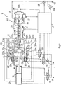
- the injection compression molding machine 1 is made up of a compression molding unit 10, an injection unit 30 and a controller A for controlling the compression molding unit 10 and the injection unit 30.
- the compression molding unit 10 includes a die opening/closing cylinder 13 located on the left side of a frame 12 that is fixed to a table 11 so as to extend to the left.
- a movable die plate 15 disposed within the frame 12 is engaged with a piston rod 14 provided for the die opening/closing cylinder 13.
- This movable die plate 15 is operated to move to the left or right by controlling pressure oil that is supplied from a pressure oil source 17 to the die opening/closing cylinder 13 or discharged reversely, the pressure oil control being performed through the energization and deenergization control of a solenoid selector valve 16 by the controller A.
- Attached to the right side of the movable die plate 15 is a movable die 18.
- a fixed die 19 is attached to the left side of the table 11.
- the fixed die 19 is provided with an inlet 20 piercing therethrough, through which a molten resinous material is fed into a mold cavity 21 formed between the dies 18 and 19.
- the compression molding unit 10 includes a die clamping apparatus 22 which locks the movable die plate 15 when the movable die 18 attached to the movable die plate 15 is placed in a position separated from the fixed die 19 by a predetermined spacing value l 1 , after the movable die plate 15 has been driven to the right by the die opening/closing cylinder 13 and which allows the locked movable die plate 15 to further move to the right thereby clamping both of the dies 18 and 19.
- the die clamping apparatus 22 is composed of a pair of following mechanisms which are respectively disposed above and below the movable die plate 15.
- Each mechanism in the die clamping apparatus 22 comprises (1) a height adjuster 22a secured to the table 11, (2) a cylinder frame 22c which is adjustable so as to move to the left or right, according to the thickness of the dies 18, 19 and to the predetermined spacing value l 1 , by means of the height adjuster 22a through a rod 22b, and (3) a link 22g and a lock cylinder 22h which are supported to the cylinder frame 22c with pins 22d, 22e respectively so as to freely pivot in the direction of arrow a, the link 22g having a die clamping cylinder 22f at the leading end thereof while the lock cylinder 22h allows the link 22g to pivot in the direction of arrow a so as to be away from or come close to the movable die plate 15.
- the die clamping cylinder 22f and the lock cylinder 22h are operated by controlling pressure oil, which is supplied from the pressure oil source 17 to the cylinders 22f, 22h or discharged reversely, through the energization and deenergization control of solenoid selector valves 23, 25 and the flow rate control of a flow control valve 24 performed by the controller A, so that the movable die plate 15 moves rightward together with the movable die 18 and the link 22g moves in the direction of arrow a.
- the injection unit 30 has a nozzle section 31 joined to the inlet 20 of the fixed die 19 in the compression molding unit 10 and a screw 35 housed in a cylinder 32.
- a resinous material such as a plastic synthetic resin
- a material hopper 33 in the form of pellet or powder is weighed, while being melted and mixed, and then injected into the mold cavity 21 via a passage 34 piercing through the nozzle section 31 and via the inlet 20 of the fixed die 19 by means of the screw 35.
- the rotation of the screw 35 for melting and mixing of the resinous material is carried out by a screw rotating motor 36.
- the screw 35 and the screw rotating motor 36 are mounted to a base plate 37.
- the base plate 37 is operated to move to the left or right by controlling pressure oil which is supplied from a pressure oil source 40 to a hydraulic piston 41 or discharged reversely, the pressure oil control being carried out through the flow rate control of a flow control valve 38 and the pressure value setting control of a solenoid relief valve 39 performed by the controller A.
- the controller A is provided with a screw positional value that is obtained by measurement with a screw position detector 42 engaged with the base plate 37. Based on the comparison between this measured screw positional value and a preset stroke value, the controller A performs control in conjunction with the forward and backward movement of the screw 35 according to a specified program so that the solenoid selector valves 16, 23, 25, the flow control valves 24, 38, and the solenoid relief valve 39 are operated and so that the rotation and stop of the screw rotating motor 36 and the switching of an opening/closing valve 43 incorporated in the passage 34 of the nozzle section 31 are controlled through a servo motor 44.
- sheet glass 50 having a thickness of 0.1mm and a specified shape is set so as to be in close contact with the inner side of the movable die 18.
- a resin film 51 made from a resinous material (described later) is affixed beforehand to the surface of the sheet glass 50, which surface is opposite to the surface contacting the movable die 18.
- the energization and deenergization control of the solenoid selector valve 16 is performed so that the movable die plate 15 is moved to the right by the die opening/closing cylinder 13 thereby, moving the movable die 18 forward.
- the energization and deenergization control of the solenoid selector valve 25 is performed to allow the lock cylinder 22h to pivot the link 22g toward the movable die plate 15. Then, the energization and deenergization control of the solenoid selector valve 23 and the flow rate control of the flow control valve 24 are performed to drive the die clamping cylinder 22f such that the right end of the die clamping cylinder 22f comes in contact with the left surface of the movable die plate 15, whereby the movable die plate 15 and therefore the movable die 18 are locked.
- the movable die plate 15 is moved to the right by the die clamping cylinder 22f, thereby moving the movable die 18 forward until the movable die 18 reaches a position that is away from the fixed die 19 by a value equal to a compression width l 2 .
- the servo motor 44 is driven to open the opening/closing valve 43 in the nozzle section 31 of the injection unit 30.
- the flow rate control of the flow control valve 38 and the pressure value setting control of the solenoid relief valve 39 are performed, thereby moving the screw 35 forward with the help of the hydraulic piston 41 to inject a molten resinous material 52 into the mold cavity 21 via the passage 34 and the inlet 20.
- the movable die 18 While the molten resinous material 52 being injected into the mold cavity 21 at a pressure of 150kg/cm 2 , the movable die 18 is moved forward to the fixed die 19 by a distance equal to the compression width l 2 by means of the die clamping cylinder 22f so that the volume of the mold cavity 21 is reduced. In this forward movement, the dies 18, 19 are kept in a parallel relationship.
- a pressure of 100kg/cm 2 which is more than the pressure required for restraining the gas contained in the molten resinous material 52 from growing to be bubbles, is uniformly applied to the entire resinous material 52 being injected so that the molten resinous material is elongated, spreading over the sheet glass 50 to form a layer of 3mm in thickness.
- the servo motor 44 is driven to close the opening/closing valve 43. At that time, the closing of the opening/closing valve 43 prevents the resinous material 52 from reversely flowing into the injection unit 30 due to the pressure of the press. The same effect can be achieved even if the opening/closing valve 43 is disposed within the resinous material passage of the die.
- the elongated, molten resinous material 52 is continuously held and compressed under a holding pressure of 15kg/cm 2 or more generated by the die clamping cylinder 22f until the molten resinous material 52 is cooled and bonded to the sheet glass 50 by virtue of the fusion of the resin film 51.
- the energization and deenergization control of the solenoid selector valve 23 is performed thereby operating the die clamping cylinder 22f to release the movable die 18 and therefore the movable die plate 15 from the locked condition. Further, the energization and deenergization control of the solenoid selector valve 25 is performed thereby operating the lock cylinder 22h to allow the link 22g to pivot, departing from the movable die plate 15. Sequentially, the energization and deenergization control of the solenoid selector valve 16 is performed thereby operating the die opening/closing cylinder 13 to move the movable die plate 15 to the left for the backward movement of the movable die 18.
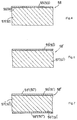
- a composite sheet material 58 in which a glass layer 55 formed from the sheet glass 50, an intermediate layer 56 formed from the resin film 51 and a resin layer 57 molded from the molten resinous material 52 are laminated in order as shown in Figure 4, is removed out of the dies 18, 19.
- the sheet glass 50 has a thickness of 0.1mm in this embodiment, the preferable thickness of the sheet glass 50 may be within the range of from 0.1 to 3mm.
- the resin layer 57 has a thickness of 3mm in this embodiment, the preferable thickness of the resin layer 57 ranges from 3mm to 6mm.
- the thickness of the sheet glass 50 and the thickness of the resin layer 57 do not necessarily fall in the above ranges but may be out of the ranges depending on applications.
- the suitable resinous material of the resin film 51 is adhesive to the sheet glass 50 and to the molding, molten resinous material 52 and can moderate the contraction difference and thermal expansion difference between the sheet glass 50 and the molding, molten resinous material 52 during molding of the molten resinous material 52 into the resin layer 57.
- a suitable resinous material for the resin film 51 By use of such a suitable resinous material for the resin film 51, the bonding strength between the glass layer 55 and the resin layer 57 can be enhanced.
- the resinous material of the resin film 51 should be transparent.
- the suitable resinous material of the resin film 51 is selected from the same thermoplastic resinous materials that can be used as the molten resinous material 52 having transparency, which are polycarbonate, acrylic resin, polystyrene, amorphous polyolefine, polyethylene terephthalate, ethylene-vinyl acetate copolymers (EVA), thermoplastic polyurethane (TPU), ethylene - acrylate - maleic anhydride ternary copolymers, hydrogenated styrene butadiene rubber (SBR hydride), polyvinyl butyral (PVB) and polyolefine elastomers.
- thermoplastic resinous materials that can be used as the molten resinous material 52 having transparency
- thermoplastic resinous materials that can be used as the molten resinous material 52 having transparency, which are polycarbonate, acrylic resin, polystyrene, amorphous polyolefine, polyethylene terephthalate, ethylene-vinyl acetate copolymers (EVA
- the pressure applied to the molten resinous material 52 to elongate it over the sheet glass 50 during molding should be no less than 15kg/cm 2 which is high enough to restrain the gas contained in the molten resinous material 52 from growing to be bubbles and this pressure should be uniformly applied to the entire molten resinous material 52.
- the intermediate layer 56 is formed by affixing the resin film 51 made from one of the materials listed above in this embodiment, the intermediate layer 56 may be formed by primer coating in which such a resinous material is applied to the joint surface of the sheet glass 50.
- the composite sheet material does not necessarily include the intermediate layer 56.
- a composite sheet material 58' as shown in Figure 5 does not include the intermediate layer but a silane coupling agent or volan is applied in pretreatment to the joint surface of sheet glass 50' that constitutes a glass layer 55' in order to enhance bonding strength.
- the composite sheet material includes the above intermediate layer 56
- mirror finishing may be applied to the joint surface of the sheet glass 50 joining to the intermediate layer 56, or a transparent conductive film such as an indium-tin oxide film may be formed on the joint surface by spattering.
- a composite sheet material 58'' includes the glass layer 55 constituting one surface thereof
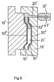
- a composite sheet material 58'' according to another embodiment has glass layers 55'', 55''' on both surfaces as shown in Figure 7.
- This composite sheet material 58'' can be produced by the arrangement shown in Figure 6 in which an inlet 20' through which a molten resinous material 52'' is injected into a mold cavity 21' is disposed aside and thin sheet glass 50'', 50''' of a specified shape is overlaid on the respective inner sides of a movable die 18' and a fixed die 19' in a close contact manner.
- Reference numerals 56' and 56'' respectively designate an intermediate layer.
- these intermediate layers 56' and 56'' may be omitted and a silane coupling agent or volan may be applied in pretreatment instead of provision of the intermediate layers 56', 56''.
- the sheet glass 50''' constituting the glass layer 55''' may be replaced by a transparent resin sheet made from one of the previously listed resinous materials such as polycarbonate, acrylic resin, polystyrene, amorphous polyolefine, polyethylene terephthalate, ethylene-vinyl acetate copolymers (EVA), thermoplastic polyurethane (TPU), ethylene - acrylate - maleic anhydride ternary copolymers, hydrogenated styrene butadiene rubber (SBR hydride), polyvinyl butyral (PVB) and polyolefine elastomers.
- resinous materials such as polycarbonate, acrylic resin, polystyrene, amorphous polyolefine, polyethylene terephthalate, ethylene-vinyl acetate cop
- the preferable resinous material of the resin sheet is harder and has a higher melting point than the resinous material of the resin layer 57.
- the intermediate layer formed by affixing a resin film or by primer coating may be provided between the resin sheet and the resin layer 57'', and printing treatment may be applied to the joint surface of the sheet glass to which the resin film is affixed or primer coating has been applied. Further, mirror finishing or a transparent conductive film may be applied to the joint surface of the resin sheet joining to the intermediate layer. Needless to say, the intermediate layer may be omitted.
- the composite sheet material may be modified to include a plurality of resin layers molded from molten resinous materials.
- a composite sheet material comprising a glass layer formed from sheet glass, a resin layer molded from a molten resinous material, a resin layer formed from a resin sheet, a resin layer molded from a molten resinous material and a resin layer formed from a resin sheet, these layers being laminated in order.
- a composite sheet material according to another example comprises a glass layer formed from sheet glass, a resin layer molded from a molten resinous material, a resin layer formed from a resin sheet, a resin layer molded from a molten resinous material, and a glass layer formed from sheet glass, these layers being laminated in order.
- the compression molding unit such as disclosed in Japanese Patent Laid-Open Publications Nos. 5-220749 (1993) and 5-285955 (1993) may be used in place of the compression molding unit 10 of the forgoing embodiment.
- a composite sheet material is injected by the hot press process such as disclosed in Japanese Patent Laid-Open Publications Nos. 4-361034 (1992) and 4-339646 (1992).
- the composite sheet material is then cooled to room temperature for subsequently carrying out easy thinning in a short time.
- the composite sheet material is pressurized for 10 seconds at a plate temperature of 150° and a pressure of 5kg/cm 2 , using the hot press disclosed in Japanese Patent Laid-Open Publication No. 8-19896 (1996) so that the solidified resin layer 57 is heated, softened and compressed to a thickness of 0.6mm to 1mm.
Abstract
A composite sheet material, in which at least either one of opposed
surfaces is composed of a glass layer for the purpose of surface protection
from scratching, can be easily produced without causing bonding defects
and stress-strain. A method of such a material is also disclosed. This
material comprises (a) a glass layer made of sheet glass and constituting
one of the opposed surfaces of the composite sheet material; and (b) a resin
layer constituting the other surface of the material and molded by applying
a uniform pressure to an entire molten resinous material introduced onto
the glass layer so as to be elongated, spreading over the glass layer, these
glass layer and said resin layer being laminated.
Description
- The present invention relates to a composite sheet material, in particular, suitable for the manufacture of windshields mounted in automobile vehicles and a method of making the same. The composite sheet material comprises a glass layer constituting one of the opposed surfaces of the material and a resin layer constituting the other surface, these layers being provided in a laminated fashion.
- Composite sheet materials often include a glass layer at at least either surface to achieve light weight and surface protection from scratching. One known type of such composite sheet materials is a laminate having a glass layer formed by bonding sheet glass to the front surface of a pre-molded resin sheet. Another type is a laminate having glass layers which are formed by bonding sheet glass to the front and rear surfaces of a pre-molded resin sheet respectively such that the resin sheet is sandwiched between the glass layers.
- These type of composite sheet materials, however, reveal the drawback that since sheet glass is bonded to a pre-molded resin sheet, gaps are created between the resin sheet and the sheet glass if the surface of the resin sheet is not flat because of warp and shrinkage and these gaps result in bonding defects.
- The invention is directed to overcoming this problem and one of the objects of the invention is therefore to provide a composite sheet material and its producing method, the material having at least a glass layer constituting either one of its opposed surfaces for the purpose of surface protection from scratching. This composite sheet material can be easily produced without causing bonding defects and is free from stress-strain.
- The above object can be accomplished by a composite sheet material according to one aspect of the invention, the material comprising:
- (a) a glass layer made of sheet glass and constituting either one of the opposed surfaces of the composite sheet material; and
- (b) a resin layer constituting the other surface of the material and
molded by applying a uniform pressure to an entire molten resinous
material introduced onto the glass layer so as to be elongated, spreading
over the glass layer,
the glass layer and the resin layer being laminated together. -
- According to another aspect of the invention, there is provided a composite sheet material comprising:
- (a) a first glass layer made of sheet glass and constituting either one of the opposed surfaces of the composite sheet material;
- (b) a second glass layer constituting the other surface of the material and made of sheet glass disposed parallel with the first glass layer; and
- (c) a resin layer formed between the first and second glass layers
and molded by applying a uniform pressure to an entire molten resinous
material introduced between the first and second glass layers so as to be
elongated, spreading over the first and second glass layers.
the first glass layer, the resin layer and the second glass layer being laminated in order. -
- According to still another aspect of the invention, there is provided a composite sheet material comprising:
- (a) a glass layer made of sheet glass and constituting either one of the opposed surfaces of the composite sheet material;
- (b) a first resin layer constituting the other surface of the material and made of a resin sheet disposed parallel with the glass layer; and
- (c) a second resin layer formed between the glass layer and the
first resin layer and molded by applying a uniform pressure to an entire
molten resinous material introduced between the glass layer and the first
resin layer so as to be elongated, spreading over the glass layer and the first
resin layer,
the glass layer, the second resin layer and the first resin layer being laminated in order. -
- The composite sheet material of the invention has a resin layer which is molded by applying a uniform pressure to an entire molten resinous material which has been introduced onto a glass layer made of sheet glass, such that the molten resinous material is elongated, spreading over the glass layer. Therefore, the composite sheet material has at least one glass layer which constitutes either surface of the material and is hardly damaged by scratching, while being free from bonding defects likely to occur between the glass layer and the resin layer. Additionally, since a uniform pressure is applied to an entire molten resinous material, thereby elongating the molten material to form the resin layer, no stress-strain is generated.
- The pressure uniformly applied to the entire molten resinous material may be high enough to restrain the gas contained in the molten resinous material from growing to be bubbles. This prevents creation of bubbles which make the resin layer turbid.
- According to a preferred embodiment of the invention, a silane coupling agent or volan is applied in pretreatment to the joint surface of the sheet glass of the glass layer which is to be joined to the resin layer. Alternatively, there may be provided an intermediate layer between the joint surfaces of the glass layer and the resin layer, the intermediate layer being made from, for example, a thermoplastic resinous material which is adhesive to the sheet glass and to the molten resinous material to be molded and which moderates the contraction difference and thermal expansion difference between the sheet glass and the molten resinous material during molding of the molten resinous material into the resin layer.
- With the above arrangement, the bonding strength between the glass layer and the resin layer can be enhanced. Prior to the formation of the resin layer, the intermediate layer may be formed by primer coating in which the above resinous material is applied to the joint surface of the sheet glass to be joined to the resin layer or alternatively formed by affixing a resin film formed from the above resinous material to the joint surface.
- The sheet glass is transparent while the molten resinous material is selected from the group consisting of polycarbonate, acrylic resin, polystyrene, amorphous polyolefine, polyethylene terephthalate, ethylene-vinyl acetate copolymers (EVA), thermoplastic polyurethane (TPU), ethylene - acrylate - maleic anhydride ternary copolymers, hydrogenated styrene butadiene rubber (SBR hydride), polyvinyl butyral (PVB) and polyolefine elastomers, and the uniform pressure applied to the entire molten resinous material is not less than 15kg/cm2 which is high enough to restrain the gas contained in the molten resinous material from growing to be bubbles. With this arrangement, the resultant composite sheet material is not turbid but transparent and free from stress-strain.
- In cases where the composite sheet material is provided with the intermediate layer, the thermoplastic resinous material from which the intermediate layer is formed can keep its transparency after the formation of the resin layer and may be selected from the group consisting of polycarbonate, acrylic resin, polystyrene, amorphous polyolefine, polyethylene terephthalate, ethylene-vinyl acetate copolymers (EVA), thermoplastic polyurethane (TPU), ethylene - acrylate - maleic anhydride ternary copolymers, hydrogenated styrene butadiene rubber (SBR hydride), polyvinyl butyral (PVB) and polyolefine elastomers. In cases where the resin layer made of a resin sheet is provided, this transparent resin sheet is preferably formed from a resinous material which is harder and has a higher melting point than the molten resinous material used in molding and selected from the group consisting of polycarbonate, acrylic resin, polystyrene, amorphous polyolefine, polyethylene terephthalate, ethylene-vinyl acetate copolymers (EVA), thermoplastic polyurethane (TPU), ethylene - acrylate - maleic anhydride ternary copolymers, hydrogenated styrene butadiene rubber (SBR hydride), polyvinyl butyral (PVB) and polyolefine elastomers.
- It should be noted that the thinner the sheet grass is, the more lightweight the resultant composite sheet material is.
- The above object can be accomplished by a method according to the invention for producing a composite sheet material having a glass layer and a resin layer which are laminated together, the method comprising the steps of:
- placing sheet glass in at least either of a pair of dies in a compression molding machine so as to come into close contact with the die;
- applying a uniform pressure to an entire molten resinous material which has been introduced into a mold cavity, such that the molten resinous material is elongated, spreading over the sheet glass; and
- closing the dies to complete compression molding.
-
- Preferably, the joint surface of the sheet glass to be joined to the resin layer molded from the molten resinous material is preliminarily coated, in primer coating, with a resinous material which is adhesive to the sheet glass and to the molten resinous material and which moderates the contraction difference and thermal expansion difference between the sheet glass and the molten resinous material during molding of the molten resinous material into the resin layer. Alternatively, a resin film formed from the above resinous material may be preliminarily affixed to the joint surface of the sheet glass.
- The resultant, composite sheet material can be made to be free from turbidty and stress-strain by using the transparent sheet glass and the molten resinous material selected from the group consisting of polycarbonate, acrylic resin, polystyrene, amorphous polyolefine, polyethylene terephthalate, ethylene-vinyl acetate copolymers (EVA), thermoplastic polyurethane (TPU), ethylene - acrylate - maleic anhydride ternary copolymers, hydrogenated styrene butadiene rubber (SBR hydride), polyvinyl butyral (PVB) and polyolefine elastomers. Further, for avoiding turbidity and stress-strain, the uniform pressure applied to the entire molten resinous material should be no less than 15kg/cm2 which is high enough to restrain the gas contained in the molten resinous material from growing to be bubbles. It should be noted that the resinous material used in the primer coating and the resinous material of the resin film to be affixed are selected from thermoplastic resinous materials, which can keep their transparency after molding, such as polycarbonate, acrylic resin, polystyrene, amorphous polyolefine, polyethylene terephthalate, ethylene-vinyl acetate copolymers (EVA), thermoplastic polyurethane (TPU), ethylene - acrylate - maleic anhydride ternary copolymers, hydrogenated styrene butadiene rubber (SBR hydride), polyvinyl butyral (PVB) and polyolefine elastomers.
- For making the resin layer thinner in some composite sheet material designs, the composite sheet material, which has been molded by elongating through the application of uniform pressure onto the entire molten resinous material, may be subjected to compression molding again wherein the composite sheet material is interposed between a first plate having a heater and a second plate parallel to the first plate and having a heater and then, the molten resinous material of the composite sheet material is again fluidized and elongated by applying a uniform pressure to the entire material. In this re-compression molding, the desirable molding temperature necessary for re-fluidizing and elongating the molten resinous material which has been once solidified is 200 °C or less and the desirable pressure necessary for re-fluidizing and elongating is 20kg/cm2 or less.
- Other objects of the present invention will become apparent from the detailed description given hereinafter. However, it should be understood that the detailed description and specific examples, while indicating a preferred embodiment of the invention, are given by way of illustration only, since various changes and modifications within the spirit and scope of the invention will become apparent to those skilled in the art from this detailed description.
-
- Figure 1 illustrates, in schematic form, the entire structure of an injection compression molding machine used in the description of a composite sheet material and its method according to the invention.
- Figures 2(a) to 2(e) illustrate, in schematic form, each step of a process for producing the composite sheet material of the invention by use of the injection compression molding machine shown in Figure 1.
- Figure 3 is a sequence chart showing the movement of a movable die and the movement of a screw during the production of the composite sheet material of the invention by use of the injection molding machine shown in Figure 1.
- Figure 4 is a sectional view of the composite sheet material produced through the steps shown in Figure 2.
- Figure 5 is a sectional view of a composite sheet material produced according to an embodiment of the invention, which does not include an intermediate layer but has undergone pretreatment wherein a silane coupling agent or volan is applied to the joint surface of sheet glass.
- Figure 6 is a schematic view corresponding to Figure 2(b), which illustrates a process for producing a composite sheet material having glass layers on both surfaces according to another embodiment of the invention.
- Figure 7 is a sectional view of the composite sheet material produced through the process shown in Figure 6.
-
- Reference is now made to the accompanying drawings to describe a composite sheet material and its producing method according to a preferred embodiment of the invention in which an injection compression molding machine is used.
- Referring to Figure 1 showing the entire schematic view of an injection compression molding machine, the injection compression molding machine 1 is made up of a
compression molding unit 10, aninjection unit 30 and a controller A for controlling thecompression molding unit 10 and theinjection unit 30. Thecompression molding unit 10 includes a die opening/closing cylinder 13 located on the left side of aframe 12 that is fixed to a table 11 so as to extend to the left. Amovable die plate 15 disposed within theframe 12 is engaged with apiston rod 14 provided for the die opening/closingcylinder 13. Thismovable die plate 15 is operated to move to the left or right by controlling pressure oil that is supplied from apressure oil source 17 to the die opening/closing cylinder 13 or discharged reversely, the pressure oil control being performed through the energization and deenergization control of asolenoid selector valve 16 by the controller A. Attached to the right side of themovable die plate 15 is amovable die 18. In opposed relation with thismovable die 18, a fixeddie 19 is attached to the left side of the table 11. The fixed die 19 is provided with aninlet 20 piercing therethrough, through which a molten resinous material is fed into amold cavity 21 formed between the dies 18 and 19. - The
compression molding unit 10 includes adie clamping apparatus 22 which locks themovable die plate 15 when themovable die 18 attached to themovable die plate 15 is placed in a position separated from the fixed die 19 by a predetermined spacing value l1, after themovable die plate 15 has been driven to the right by the die opening/closing cylinder 13 and which allows the lockedmovable die plate 15 to further move to the right thereby clamping both of the dies 18 and 19. Thedie clamping apparatus 22 is composed of a pair of following mechanisms which are respectively disposed above and below themovable die plate 15. - Each mechanism in the
die clamping apparatus 22 comprises (1) aheight adjuster 22a secured to the table 11, (2) acylinder frame 22c which is adjustable so as to move to the left or right, according to the thickness of the dies 18, 19 and to the predetermined spacing value l1, by means of theheight adjuster 22a through arod 22b, and (3) a link 22g and alock cylinder 22h which are supported to thecylinder frame 22c withpins die clamping cylinder 22f at the leading end thereof while thelock cylinder 22h allows the link 22g to pivot in the direction of arrow a so as to be away from or come close to themovable die plate 15. It should be noted that thedie clamping cylinder 22f and thelock cylinder 22h are operated by controlling pressure oil, which is supplied from thepressure oil source 17 to thecylinders solenoid selector valves flow control valve 24 performed by the controller A, so that themovable die plate 15 moves rightward together with themovable die 18 and the link 22g moves in the direction of arrow a. - Next, the
injection unit 30 will be described. Theinjection unit 30 has anozzle section 31 joined to theinlet 20 of the fixed die 19 in thecompression molding unit 10 and ascrew 35 housed in acylinder 32. In theheated cylinder 32, a resinous material (such as a plastic synthetic resin) fed from amaterial hopper 33 in the form of pellet or powder is weighed, while being melted and mixed, and then injected into themold cavity 21 via a passage 34 piercing through thenozzle section 31 and via theinlet 20 of the fixed die 19 by means of thescrew 35. The rotation of thescrew 35 for melting and mixing of the resinous material is carried out by ascrew rotating motor 36. Thescrew 35 and thescrew rotating motor 36 are mounted to abase plate 37. Thebase plate 37 is operated to move to the left or right by controlling pressure oil which is supplied from apressure oil source 40 to ahydraulic piston 41 or discharged reversely, the pressure oil control being carried out through the flow rate control of aflow control valve 38 and the pressure value setting control of asolenoid relief valve 39 performed by the controller A. In other words, not only the forward and backward movement of thescrew 35 relative to thenozzle section 31 for weighing of the molten resinous material to be injected and for injection of the weighed molten resinous material into themold cavity 21, but also the application of a predetermined pressing force to thescrew 35 for the purpose of applying a predetermined injection pressure to the molten resinous material within thecylinder 32 is carried out through thebase plate 37 by supplying pressure oil to thehydraulic piston 41 or discharging it therefrom. - The controller A is provided with a screw positional value that is obtained by measurement with a
screw position detector 42 engaged with thebase plate 37. Based on the comparison between this measured screw positional value and a preset stroke value, the controller A performs control in conjunction with the forward and backward movement of thescrew 35 according to a specified program so that thesolenoid selector valves flow control valves solenoid relief valve 39 are operated and so that the rotation and stop of thescrew rotating motor 36 and the switching of an opening/closingvalve 43 incorporated in the passage 34 of thenozzle section 31 are controlled through aservo motor 44. - With reference to Figures 2(a) to 2(e) and Figure 3, there will be explained the steps of a method for producing the composite sheet material by use of the injection compression molding machine 1 of the above-described structure according to the invention. It should be noted that Stages I to VII in Figure 3 correspond to the steps (I) to (VII) in the following description respectively.
- In this embodiment, when the
movable die 18 is in a position separated from the fixed die 19 by more than the predetermined spacing value l1,sheet glass 50 having a thickness of 0.1mm and a specified shape is set so as to be in close contact with the inner side of themovable die 18. Aresin film 51 made from a resinous material (described later) is affixed beforehand to the surface of thesheet glass 50, which surface is opposite to the surface contacting themovable die 18. - Until the spacing between the
movable die 18 holding thesheet glass 50 on its inner side and the fixeddie 19 becomes equal to the predetermined spacing value l1, the energization and deenergization control of thesolenoid selector valve 16 is performed so that themovable die plate 15 is moved to the right by the die opening/closing cylinder 13 thereby, moving themovable die 18 forward. - When the
movable die 18 has reached a position located the predetermined spacing value l1 away from the fixeddie 19, the energization and deenergization control of thesolenoid selector valve 25 is performed to allow thelock cylinder 22h to pivot the link 22g toward themovable die plate 15. Then, the energization and deenergization control of thesolenoid selector valve 23 and the flow rate control of theflow control valve 24 are performed to drive thedie clamping cylinder 22f such that the right end of thedie clamping cylinder 22f comes in contact with the left surface of themovable die plate 15, whereby themovable die plate 15 and therefore themovable die 18 are locked. Sequentially, themovable die plate 15 is moved to the right by thedie clamping cylinder 22f, thereby moving themovable die 18 forward until themovable die 18 reaches a position that is away from the fixed die 19 by a value equal to a compression width l2. - When the
movable die 18 has reached a position away from the fixed die 19 by a value equal to the compression width l2, theservo motor 44 is driven to open the opening/closingvalve 43 in thenozzle section 31 of theinjection unit 30. In the mean time, the flow rate control of theflow control valve 38 and the pressure value setting control of thesolenoid relief valve 39 are performed, thereby moving thescrew 35 forward with the help of thehydraulic piston 41 to inject amolten resinous material 52 into themold cavity 21 via the passage 34 and theinlet 20. The pressure for injection feeding in this embodiment is 150kg/cm2 that is more than the pressure (= 15kg/cm2) required for restraining the gas contained in themolten resinous material 52 from growing to be bubbles. - While the
molten resinous material 52 being injected into themold cavity 21 at a pressure of 150kg/cm2, themovable die 18 is moved forward to the fixed die 19 by a distance equal to the compression width l2 by means of thedie clamping cylinder 22f so that the volume of themold cavity 21 is reduced. In this forward movement, the dies 18, 19 are kept in a parallel relationship. A pressure of 100kg/cm2, which is more than the pressure required for restraining the gas contained in themolten resinous material 52 from growing to be bubbles, is uniformly applied to theentire resinous material 52 being injected so that the molten resinous material is elongated, spreading over thesheet glass 50 to form a layer of 3mm in thickness. When theresinous material 52 in its molten state has been fed to themold cavity 21 in an amount necessary for molding, theservo motor 44 is driven to close the opening/closingvalve 43. At that time, the closing of the opening/closingvalve 43 prevents theresinous material 52 from reversely flowing into theinjection unit 30 due to the pressure of the press. The same effect can be achieved even if the opening/closingvalve 43 is disposed within the resinous material passage of the die. - While the volume of the
mold cavity 21 being reduced by moving themovable die 18 forward to the fixed die 19 by a distance equal to the compression width l2(= l1 - a thickness of 3mm (in this embodiment)), the elongated,molten resinous material 52 is continuously held and compressed under a holding pressure of 15kg/cm2 or more generated by thedie clamping cylinder 22f until themolten resinous material 52 is cooled and bonded to thesheet glass 50 by virtue of the fusion of theresin film 51. - After cooling the
molten resinous material 52, the energization and deenergization control of thesolenoid selector valve 23 is performed thereby operating thedie clamping cylinder 22f to release themovable die 18 and therefore themovable die plate 15 from the locked condition. Further, the energization and deenergization control of thesolenoid selector valve 25 is performed thereby operating thelock cylinder 22h to allow the link 22g to pivot, departing from themovable die plate 15. Sequentially, the energization and deenergization control of thesolenoid selector valve 16 is performed thereby operating the die opening/closing cylinder 13 to move themovable die plate 15 to the left for the backward movement of themovable die 18. In this way, acomposite sheet material 58, in which aglass layer 55 formed from thesheet glass 50, anintermediate layer 56 formed from theresin film 51 and aresin layer 57 molded from themolten resinous material 52 are laminated in order as shown in Figure 4, is removed out of the dies 18, 19. - Although the
sheet glass 50 has a thickness of 0.1mm in this embodiment, the preferable thickness of thesheet glass 50 may be within the range of from 0.1 to 3mm. Although theresin layer 57 has a thickness of 3mm in this embodiment, the preferable thickness of theresin layer 57 ranges from 3mm to 6mm. Of course, the thickness of thesheet glass 50 and the thickness of theresin layer 57 do not necessarily fall in the above ranges but may be out of the ranges depending on applications. - The suitable resinous material of the
resin film 51 is adhesive to thesheet glass 50 and to the molding,molten resinous material 52 and can moderate the contraction difference and thermal expansion difference between thesheet glass 50 and the molding,molten resinous material 52 during molding of themolten resinous material 52 into theresin layer 57. By use of such a suitable resinous material for theresin film 51, the bonding strength between theglass layer 55 and theresin layer 57 can be enhanced. For providing transparency to the resultantcomposite sheet material 58, not only thesheet glass 50 but also the resinous material of theresin film 51 should be transparent. The suitable resinous material of theresin film 51 is selected from the same thermoplastic resinous materials that can be used as themolten resinous material 52 having transparency, which are polycarbonate, acrylic resin, polystyrene, amorphous polyolefine, polyethylene terephthalate, ethylene-vinyl acetate copolymers (EVA), thermoplastic polyurethane (TPU), ethylene - acrylate - maleic anhydride ternary copolymers, hydrogenated styrene butadiene rubber (SBR hydride), polyvinyl butyral (PVB) and polyolefine elastomers. For producing thecomposite sheet material 58 which is free from free from turbidity and stress-strain, the pressure applied to themolten resinous material 52 to elongate it over thesheet glass 50 during molding should be no less than 15kg/cm2 which is high enough to restrain the gas contained in themolten resinous material 52 from growing to be bubbles and this pressure should be uniformly applied to the entiremolten resinous material 52. - While the
intermediate layer 56 is formed by affixing theresin film 51 made from one of the materials listed above in this embodiment, theintermediate layer 56 may be formed by primer coating in which such a resinous material is applied to the joint surface of thesheet glass 50. The composite sheet material does not necessarily include theintermediate layer 56. According to another embodiment, a composite sheet material 58' as shown in Figure 5 does not include the intermediate layer but a silane coupling agent or volan is applied in pretreatment to the joint surface of sheet glass 50' that constitutes a glass layer 55' in order to enhance bonding strength. - It should be noted that in cases where the composite sheet material includes the above
intermediate layer 56, it is possible to apply printing treatment to the joint surface of thesheet glass 50 to which theabove resin film 51 is affixed or primer coating has been applied. Also, mirror finishing may be applied to the joint surface of thesheet glass 50 joining to theintermediate layer 56, or a transparent conductive film such as an indium-tin oxide film may be formed on the joint surface by spattering. - While the
composite sheet material 58 in this embodiment includes theglass layer 55 constituting one surface thereof, a composite sheet material 58'' according to another embodiment has glass layers 55'', 55''' on both surfaces as shown in Figure 7. This composite sheet material 58'' can be produced by the arrangement shown in Figure 6 in which an inlet 20' through which a molten resinous material 52'' is injected into a mold cavity 21' is disposed aside and thin sheet glass 50'', 50''' of a specified shape is overlaid on the respective inner sides of a movable die 18' and a fixed die 19' in a close contact manner. Reference numerals 56' and 56'' respectively designate an intermediate layer. As a matter of course, these intermediate layers 56' and 56'' may be omitted and a silane coupling agent or volan may be applied in pretreatment instead of provision of the intermediate layers 56', 56''. Additionally, the sheet glass 50''' constituting the glass layer 55''' may be replaced by a transparent resin sheet made from one of the previously listed resinous materials such as polycarbonate, acrylic resin, polystyrene, amorphous polyolefine, polyethylene terephthalate, ethylene-vinyl acetate copolymers (EVA), thermoplastic polyurethane (TPU), ethylene - acrylate - maleic anhydride ternary copolymers, hydrogenated styrene butadiene rubber (SBR hydride), polyvinyl butyral (PVB) and polyolefine elastomers. In this case, the preferable resinous material of the resin sheet is harder and has a higher melting point than the resinous material of theresin layer 57. Additionally, the intermediate layer formed by affixing a resin film or by primer coating may be provided between the resin sheet and the resin layer 57'', and printing treatment may be applied to the joint surface of the sheet glass to which the resin film is affixed or primer coating has been applied. Further, mirror finishing or a transparent conductive film may be applied to the joint surface of the resin sheet joining to the intermediate layer. Needless to say, the intermediate layer may be omitted. - An impact test was conducted using the
composite sheet material 58 in which a 0.1mm-thick glass layer 55, a 0.4mm-thickintermediate layer 56 of theresin film 51 made from thermoplastic polyurethane (resinous material) and a 6mm-thick resin layer 57 formed from a polycarbonate were laminated. From 1m above thecomposite sheet material 58, a steel ball of 225g in weight was naturally dropped onto thiscomposite sheet material 58 with theglass layer 55 facing up. As a result, no cracks were observed in theglass layer 55. - The composite sheet material may be modified to include a plurality of resin layers molded from molten resinous materials. For example, there may be provided a composite sheet material comprising a glass layer formed from sheet glass, a resin layer molded from a molten resinous material, a resin layer formed from a resin sheet, a resin layer molded from a molten resinous material and a resin layer formed from a resin sheet, these layers being laminated in order. A composite sheet material according to another example comprises a glass layer formed from sheet glass, a resin layer molded from a molten resinous material, a resin layer formed from a resin sheet, a resin layer molded from a molten resinous material, and a glass layer formed from sheet glass, these layers being laminated in order.
- The compression molding unit such as disclosed in Japanese Patent Laid-Open Publications Nos. 5-220749 (1993) and 5-285955 (1993) may be used in place of the
compression molding unit 10 of the forgoing embodiment. - For making the
resin layer 57 thinner to meet the requirement in some composite sheet material designs, the following procedure is taken: A composite sheet material is injected by the hot press process such as disclosed in Japanese Patent Laid-Open Publications Nos. 4-361034 (1992) and 4-339646 (1992). The composite sheet material is then cooled to room temperature for subsequently carrying out easy thinning in a short time. After that, the composite sheet material is pressurized for 10 seconds at a plate temperature of 150° and a pressure of 5kg/cm2, using the hot press disclosed in Japanese Patent Laid-Open Publication No. 8-19896 (1996) so that the solidifiedresin layer 57 is heated, softened and compressed to a thickness of 0.6mm to 1mm. - The invention being thus described, it will be obvious that the same may be varied in many ways. Such variations are not to be regarded as a departure from the spirit and scope of the invention, and all such modifications as would be obvious to one skilled in the art are intended to be included within the scope of the following claims.
Claims (43)
- A composite sheet material comprising:(a) a glass layer made of sheet glass and constituting either one of the opposed surfaces of the composite sheet material; and(b) a resin layer constituting the other surface of the material and molded by applying a uniform pressure to an entire molten resinous material introduced onto the glass layer so as to be elongated, spreading over the glass layer,
said glass layer and said resin layer being laminated together. - A composite sheet material according to claim 1, wherein said uniform pressure applied to the entire molten resinous material is high enough to restrain gas contained in the molten resinous material from growing to be bubbles.
- A composite sheet material according to claim 1 or 2, wherein the joint surface of the sheet glass of said glass layer joining to said resin layer is coated with a silane coupling agent or volan in pretreatment.
- A composite sheet material according to claim 2, wherein said sheet glass is transparent and said molten resinous material is selected from the group consisting of polycarbonate, acrylic resin, polystyrene, amorphous polyolefine, polyethylene terephthalate, ethylene-vinyl acetate copolymers (EVA), thermoplastic polyurethane (TPU), ethylene - acrylate - maleic anhydride ternary copolymers, hydrogenated styrene butadiene rubber (SBR hydride), polyvinyl butyral (PVB) and polyolefine elastomers, and wherein the uniform pressure applied to the entire molten resinous material is not less than 15kg/cm2 which is high enough to restrain gas contained in the molten resinous material from growing to be bubbles.
- A composite sheet material according to claim 1 or 2, wherein the joint surface of the sheet glass of said glass layer joining to said resin layer is provided with mirror finishing or coated with a transparent conductive film.
- A composite sheet material according to claim 1, wherein an intermediate layer made from a resinous material is provided between the joint surfaces of said glass layer and said resin layer.
- A composite sheet material according to claim 6, wherein the resinous material of said intermediate layer is adhesive to the sheet glass and to the molding, molten resinous material and moderates the contraction difference and thermal expansion difference between the sheet glass and the molten resinous material during molding of the molten resinous material into the resin layer.
- A composite sheet material according to claim 6, wherein said intermediate layer is formed by applying primer coating or affixing a resin film made from the resinous material of the intermediate layer to the joint surface of the sheet glass joining to the resin layer, prior to the formation of the resin layer.
- A composite sheet material according to claim 6, wherein the joint surface of the sheet glass constituting said glass layer joining to said intermediate layer is provided with mirror finishing or coated with a transparent conductive film.
- A composite sheet material according to claim 8, wherein printing treatment is applied to the joint surface of the sheet glass to which primer coating has been applied or the resin film has been affixed.
- A composite sheet material comprising:(a) a first glass layer made of sheet glass and constituting either one of the opposed surfaces of the composite sheet material;(b) a second glass layer constituting the other surface of the material and made of sheet glass disposed parallel with said first glass layer; and(c) a resin layer formed between the first and second glass layers and molded by applying a uniform pressure to an entire molten resinous material introduced between the first and second glass layers so as to be elongated, spreading over the first and second glass layers,
the first glass layer, the resin layer and the second glass layer being laminated in order. - A composite sheet material according to claim 11, wherein said uniform pressure applied to the molten resinous material is high enough to restrain gas contained in the molten resinous material from growing to be bubbles.
- A composite sheet material according to claim 11 or 12, wherein a silane coupling agent or volan is applied, in pretreatment, to at least either the joint surface of the sheet glass of the first glass layer joining to the resin layer or the joint surface of the sheet glass of the second glass layer joining to the resin layer.
- A composite sheet material according to claim 12, wherein the sheet glasses of said first glass layer and said second glass layer are transparent, whereas said molten resinous material is selected from the group consisting of polycarbonate, acrylic resin, polystyrene, amorphous polyolefine, polyethylene terephthalate, ethylene-vinyl acetate copolymers (EVA), thermoplastic polyurethane (TPU), ethylene - acrylate - maleic anhydride ternary copolymers, hydrogenated styrene butadiene rubber (SBR hydride), polyvinyl butyral (PVB) and polyolefine elastomers, and wherein the uniform pressure applied to the entire molten resinous material is not less than 15kg/cm2 which is high enough to restrain gas contained in the molten resinous material from growing to be bubbles.
- A composite sheet material according to claim 11 or 12, wherein at least either the joint surface of the sheet glass of said first glass layer joining to said resin layer or the joint surface of the sheet glass of said second glass layer joining to said resin layer is provided with mirror finishing or coated with a transparent conductive film.
- A composite sheet material according to claim 11, wherein an intermediate layer made from a resinous material is provided at least between the joint surfaces of said first glass layer and said resin layer or between the joint surfaces of said second glass layer and said resin layer.
- A composite sheet material according to claim 16, wherein the resinous material of said intermediate layer is adhesive to the sheet glass of the first or second glass layer and to the molding, molten resinous material and moderates the contraction difference and thermal expansion difference between the sheet glass of the first or second glass layer and the molten resinous material during molding of the molten resinous material into the resin layer.
- A composite sheet material according to claim 7 or 17, wherein said resinous material of said intermediate layer is a thermoplastic resinous material.
- A composite sheet material according to claim 18, wherein said resinous material of said intermediate layer keeps its transparency after molding said resin layer.
- A composite sheet material according to claim 19, wherein the sheet glasses of said first glass layer and said second glass layer are transparent, whereas said molten resinous material is selected from the group consisting of polycarbonate, acrylic resin, polystyrene, amorphous polyolefine, polyethylene terephthalate, ethylene-vinyl acetate copolymers (EVA), thermoplastic polyurethane (TPU), ethylene - acrylate - maleic anhydride ternary copolymers, hydrogenated styrene butadiene rubber (SBR hydride), polyvinyl butyral (PVB) and polyolefine elastomers, wherein said uniform pressure applied to the entire molten resinous material is not less than 15kg/cm2 which is high enough to restrain gas contained in the molten resinous material from growing to be bubbles, and wherein said thermoplastic resinous material of said intermediate layer is selected from the group consisting of polycarbonate, acrylic resin, polystyrene, amorphous polyolefine, polyethylene terephthalate, ethylene-vinyl acetate copolymers (EVA), thermoplastic polyurethane (TPU), ethylene - acrylate - maleic anhydride ternary copolymers, hydrogenated styrene butadiene rubber (SBR hydride), polyvinyl butyral (PVB) and polyolefine elastomers.
- A composite sheet material according to claim 16, wherein said intermediate layer is formed by applying primer coating or affixing a resin film made from the resinous material of the intermediate layer to the joint surface of the sheet glass of the first or second glass layer joining to the resin layer, prior to the formation of the resin layer.
- A composite sheet material according to claim 16, wherein the joint surface of the sheet glass of the first or second glass layer joining to said intermediate layer is provided with mirror finishing or coated with a transparent conductive film.
- A composite sheet material according to claim 21, wherein printing treatment is applied to the joint surface of the sheet glass to which primer coating has been applied or the resin film has been affixed.
- A composite sheet material comprising:(a) a glass layer made of sheet glass and constituting either one of the opposed surfaces of the composite sheet material;(b) a first resin layer constituting the other surface of the material and made of a resin sheet disposed parallel with said glass layer; and(c) a second resin layer formed between the glass layer and the first resin layer and molded by applying a uniform pressure to an entire molten resinous material introduced between the glass layer and the first resin layer so as to be elongated, spreading over the glass layer and the first resin layer,
the glass layer, the second resin layer and the first resin layer being laminated in order. - A composite sheet material according to claim 24, wherein said uniform pressure applied to the entire molten resinous material is high enough to restrain gas contained in the molten resinous material from growing to be bubbles.
- A composite sheet material according to claim 24 or 25, wherein at least the joint surface of the sheet glass of said glass layer joining to said second resin layer is coated with a silane coupling agent or volan in pretreatment.
- A composite sheet material according to claim 25, wherein said sheet glass and said resin sheet are transparent, whereas said molten resinous material is selected from the group consisting of polycarbonate, acrylic resin, polystyrene, amorphous polyolefine, polyethylene terephthalate, ethylene-vinyl acetate copolymers (EVA), thermoplastic polyurethane (TPU), ethylene - acrylate - maleic anhydride ternary copolymers, hydrogenated styrene butadiene rubber (SBR hydride), polyvinyl butyral (PVB) and polyolefine elastomers, and wherein the uniform pressure applied to the entire molten resinous material is not less than 15kg/cm2 which is high enough to restrain gas contained in the molten resinous material from growing to be bubbles.
- A composite sheet material according to claim 24 or 25, wherein the joint surface of the sheet glass of said glass layer joining to said second resin layer is provided with mirror finishing or coated with a transparent conductive film.
- A composite sheet material according to claim 24, wherein an intermediate layer made from a resinous material is provided between the joint surfaces of said glass layer and said second resin layer.
- A composite sheet material according to claim 29, wherein the resinous material of said intermediate layer is adhesive to the sheet glass and to the molding, molten resinous material and moderates the contraction difference and thermal expansion difference between the sheet glass and the molten resinous material during molding of the molten resinous material into the second resin layer.
- A composite sheet material according to claim 30, wherein said resinous material of said intermediate layer is a thermoplastic resinous material.
- A composite sheet material according to claim 31, wherein said resinous material of said intermediate layer keeps its transparency after molding of the second resin layer.
- A composite sheet material according to claim 32, wherein said sheet glass and said resin sheet are transparent, whereas said molding, molten resinous material is selected from the group consisting of polycarbonate, acrylic resin, polystyrene, amorphous polyolefine, polyethylene terephthalate, ethylene-vinyl acetate copolymers (EVA), thermoplastic polyurethane (TPU), ethylene - acrylate - maleic anhydride ternary copolymers, hydrogenated styrene butadiene rubber (SBR hydride), polyvinyl butyral (PVB) and polyolefine elastomers, wherein the uniform pressure applied to the entire molten resinous material is not less than 15kg/cm2 which is high enough to restrain gas contained in the molten resinous material from growing to be bubbles, and wherein said thermoplastic resinous material of said intermediate layer is selected from the group consisting of polycarbonate, acrylic resin, polystyrene, amorphous polyolefine, polyethylene terephthalate, ethylene-vinyl acetate copolymers (EVA), thermoplastic polyurethane (TPU), ethylene - acrylate - maleic anhydride ternary copolymers, hydrogenated styrene butadiene rubber (SBR hydride), polyvinyl butyral (PVB) and polyolefine elastomers.
- A composite sheet material according to claim 29, wherein said intermediate layer is formed by applying primer coating or affixing a resin film made from the resinous material of the intermediate layer to the joint surface of the sheet glass joining to the second resin layer, prior to the formation of the second resin layer.
- A composite sheet material according to claim 29, wherein the joint surface of the sheet glass of said glass layer joining to said intermediate layer is provided with mirror finishing or coated with a transparent conductive film.
- A composite sheet material according to claim 34, wherein printing treatment is applied to the joint surface of the sheet glass to which primer coating has been applied or the resin film has been affixed.
- A composite sheet material according to claim 1, 2, 11, 12, 24 or 25, wherein said molding of the molten resinous material by applying a uniform pressure to the entire molten resinous material so as to be elongated is carried out with a compression molding machine for molding products by compressing a molten resinous material supplied to die cavities.
- A method for producing a composite sheet material having a glass layer and a resin layer which are laminated together, the method comprising the steps of:placing sheet glass in at least either of a pair of dies in a compression molding machine so as to come into close contact with the die;applying a uniform pressure to an entire molten resinous material which has been introduced into a mold cavity, such that the molten resinous material is elongated, spreading over the sheet glass; andclosing the dies to complete compression molding.
- A composite sheet material producing method according to claim 38, wherein said uniform pressure applied to the entire molten resinous material is high enough to restrain gas contained in the molten resinous material from growing to be bubbles.
- A composite sheet material producing method according to claim 38 or 39, wherein the joint surface of said sheet glass joining to the resin layer molded from said molten resinous material undergoes primer coating treatment to be coated with a resinous material or is preliminarily provided with a resin film of said resinous material,said resinous material used in the primer coating and constituting the resin firm being adhesive to the sheet glass and to the molding, molten resinous material and moderating the contraction difference and thermal expansion difference between the sheet glass and the molten resinous material during molding of the molten resinous material into the resin layer.
- A composite sheet material producing method according to claim 40, wherein printing treatment is applied to the joint surface of the sheet glass to which primer coating has been applied or the resin film has been affixed.
- A composite sheet material producing method according to claim 38 or 39, wherein the composite sheet material, which has been molded trough elongation by applying the uniform pressure onto the entire molten resinous material, is subjected to compression molding again wherein the composite sheet material is interposed between a first plate having a heater and a second plate parallel to the first plate and having a heater and then, the molten resinous material of the composite sheet material is again fluidized and elongated by applying heat and a uniform pressure to the entire molten resinous material.
- A composite sheet material producing method according to claim 42, wherein, in said re-compression molding, the molding temperature and pressure necessary for re-fluidizing and elongating the molten resinous material which has been once solidified are 200 ° or less and 20kg/cm2 or less, respectively.
Applications Claiming Priority (3)
| Application Number | Priority Date | Filing Date | Title |
|---|---|---|---|
| JP8100569A JPH09286039A (en) | 1996-04-22 | 1996-04-22 | Plate-shaped composite and its production |
| JP100569/96 | 1996-04-22 | ||
| PCT/JP1997/001190 WO1997039869A1 (en) | 1996-04-22 | 1997-04-07 | Plate-like composite material and method of producing the same |
Publications (2)
| Publication Number | Publication Date |
|---|---|
| EP0908287A1 true EP0908287A1 (en) | 1999-04-14 |
| EP0908287A4 EP0908287A4 (en) | 1999-08-11 |
Family
ID=14277549
Family Applications (1)
| Application Number | Title | Priority Date | Filing Date |
|---|---|---|---|
| EP97914625A Withdrawn EP0908287A4 (en) | 1996-04-22 | 1997-04-07 | Plate-like composite material and method of producing the same |
Country Status (4)
| Country | Link |
|---|---|
| US (1) | US6296799B1 (en) |
| EP (1) | EP0908287A4 (en) |
| JP (1) | JPH09286039A (en) |
| WO (1) | WO1997039869A1 (en) |
Cited By (3)
| Publication number | Priority date | Publication date | Assignee | Title |
|---|---|---|---|---|
| EP1445084A1 (en) * | 2003-02-07 | 2004-08-11 | Creative Plastics International Limited | A method of forming a decorative glass/resin laminate and laminate made by the method |
| WO2008024805A1 (en) * | 2006-08-23 | 2008-02-28 | Solutia Incorporated | Injection molded multiple layer glazings |
| AU2012201329B2 (en) * | 2006-08-23 | 2013-08-15 | Solutia Inc. | Injection molded multiple layer glazings |
Families Citing this family (20)
| Publication number | Priority date | Publication date | Assignee | Title |
|---|---|---|---|---|
| JPH11138668A (en) | 1997-11-12 | 1999-05-25 | Komatsu Ltd | Plate-like structural body and manufacture thereof |
| US6777482B2 (en) | 2002-04-04 | 2004-08-17 | Owens Corning Fiberglas Technology, Inc. | Alternative polyolefin composite veil/compatibilizing mat material |
| US20040046274A1 (en) * | 2002-09-06 | 2004-03-11 | Chi-Kung Wu | Method for producing a wear-resisting outsole |
| US7981342B2 (en) * | 2003-12-31 | 2011-07-19 | International Automotive Components Group North America, Inc. | In-mold lamination of decorative products |
| JP2006310154A (en) * | 2005-04-28 | 2006-11-09 | Bussan Nanotech Research Institute Inc | Transparent conductive film and coating composition for the transparent conductive film |
| JP5295533B2 (en) * | 2006-10-31 | 2013-09-18 | 日東電工株式会社 | Surface protective film and optical film with surface protective film |
| EP2117799A4 (en) * | 2007-01-17 | 2011-11-16 | Int Automotive Components | Decorative products having depth of image |
| DE102009021938A1 (en) * | 2009-05-19 | 2010-11-25 | Nyssen, Siegfried, Dr. | Laminated glass pane useful as motor vehicle glass pane or wall cladding, comprises a plastic plate made of transparent plastic, and a glass layer that is tightly connected with the plastic plate |
| JP5721698B2 (en) * | 2010-03-26 | 2015-05-20 | 三菱重工プラスチックテクノロジー株式会社 | Manufacturing method of fiber reinforced composite material |
| US8269972B2 (en) | 2010-06-29 | 2012-09-18 | Honeywell International Inc. | Beam intensity detection in a cavity ring down sensor |
| US8437000B2 (en) | 2010-06-29 | 2013-05-07 | Honeywell International Inc. | Multiple wavelength cavity ring down gas sensor |
| US8322191B2 (en) | 2010-06-30 | 2012-12-04 | Honeywell International Inc. | Enhanced cavity for a photoacoustic gas sensor |
| EP3085510A4 (en) | 2013-12-16 | 2017-07-26 | Asahi Glass Company, Limited | Glass-resin laminate and method for producing same |
| DE102015218142A1 (en) | 2015-09-22 | 2017-03-23 | Volkswagen Aktiengesellschaft | Method for producing a composite component |
| WO2017051383A1 (en) * | 2015-09-25 | 2017-03-30 | Sabic Global Technologies B.V. | Method of molding using mold inserts and apparatus therefor |
| KR102203067B1 (en) * | 2018-10-16 | 2021-01-14 | 주식회사 서연이화 | polycarbonate glazing for car and method of producing the same |
| CN110587910A (en) * | 2019-09-12 | 2019-12-20 | 中国航发北京航空材料研究院 | Injection molding method of composite structure transparent part |
| KR102363856B1 (en) * | 2019-09-24 | 2022-02-17 | 주식회사 서연이화 | method of producing polycarbonate glazing for car |
| CN112874073B (en) * | 2021-01-20 | 2022-07-26 | 浙江水墨江南新材料科技有限公司 | Resin decorative board and manufacturing method |
| CN113443841B (en) * | 2021-08-02 | 2022-04-19 | 南京宣汉玻璃有限公司 | Bonding device for new glass material for resisting solar and electromagnetic radiation and production method of new glass material |
Citations (11)
| Publication number | Priority date | Publication date | Assignee | Title |
|---|---|---|---|---|
| US2084113A (en) * | 1935-03-23 | 1937-06-15 | Duplate Corp | Process and apparatus for making safety glass |
| US3382137A (en) * | 1964-09-18 | 1968-05-07 | Corning Glass Works | Laminated structures and method for preparing such structures |
| GB1184042A (en) * | 1966-02-16 | 1970-03-11 | Speigelglas Ag Deutsche | Coated Plastics Sheet Material |
| US3666614A (en) * | 1969-06-24 | 1972-05-30 | Union Carbide Corp | Glass-polycarbonate resin laminates |
| GB2008480A (en) * | 1977-11-04 | 1979-06-06 | Corning Glass Works | Direct casting method for producing low-stress glass/plastic composites |
| US4724023A (en) * | 1985-04-09 | 1988-02-09 | E M Partners Ag | Method of making laminated glass |
| EP0490580A1 (en) * | 1990-12-11 | 1992-06-17 | Pilkington Glass Limited | Method of laminating glass sheets and laminated glass article |
| DE4212944A1 (en) * | 1992-04-18 | 1993-10-21 | Docter Optic Wetzlar Gmbh | Geometrically accurate glass prodn. - uses external pressure on glass against master surface, for further glass to be bonded with putty |
| US5264160A (en) * | 1991-04-30 | 1993-11-23 | Canon Kabushiki Kaisha | Method of molding optical elements |
| GB2279294A (en) * | 1993-07-01 | 1995-01-04 | Michael Stephen Aho | Strengthened glass laminated products |
| EP0669205A1 (en) * | 1994-02-25 | 1995-08-30 | DORNIER GmbH | Glazing panel |
Family Cites Families (19)
| Publication number | Priority date | Publication date | Assignee | Title |
|---|---|---|---|---|
| US3620905A (en) * | 1969-10-21 | 1971-11-16 | Du Pont | Optically clear thermoplastic polyurethanes |
| JPS5936800B2 (en) | 1976-08-30 | 1984-09-05 | 沖エンジニアリング株式会社 | Vehicle separation identification device |
| ZA824094B (en) | 1981-06-19 | 1983-07-27 | Ici Plc | A process for the manufacture of cephalosporin derivative |
| JPS63262241A (en) * | 1987-04-21 | 1988-10-28 | 旭化成株式会社 | Laminate |
| JPH07166B2 (en) | 1987-09-24 | 1995-01-11 | 三菱重工業株式会社 | CO adsorption separation method |
| JPH0520523Y2 (en) * | 1987-11-18 | 1993-05-27 | ||
| FR2634753B1 (en) * | 1988-07-27 | 1992-08-21 | Saint Gobain Vitrage | GLAZING WITH ELECTRICALLY CONDUCTIVE LAYER OBTAINED BY PYROLYSIS OF POWDERED COMPOUNDS, USEFUL AS A WINDSCREEN FOR A MOTOR VEHICLE |
| GB9009066D0 (en) | 1990-04-23 | 1990-06-20 | Hickman James A A | Method of laminating glass |
| JP2970062B2 (en) * | 1991-06-12 | 1999-11-02 | 住友化学工業株式会社 | Molding method of multilayer molded product |
| JPH05514A (en) | 1991-06-24 | 1993-01-08 | Ricoh Co Ltd | Storage device having function of preventing ink delivery nozzle from clogging |
| JP3036916B2 (en) * | 1991-09-27 | 2000-04-24 | 積水化学工業株式会社 | Laminated safety glass |
| JP3039070B2 (en) | 1991-10-09 | 2000-05-08 | 住友電気工業株式会社 | Fluororesin coating |
| JPH05208467A (en) * | 1991-10-23 | 1993-08-20 | Sumitomo Chem Co Ltd | Multi-layer molded body and production thereof |
| FR2691112B1 (en) * | 1992-05-14 | 1995-07-21 | Saint Gobain Vitrage Int | PROCESS FOR ENCAPSULATION OF GLAZING AND GLAZING THUS OBTAINED. |
| JPH07205374A (en) * | 1993-07-28 | 1995-08-08 | Asahi Glass Co Ltd | Laminated glass and production of laminated glass |
| US5545277A (en) | 1994-10-03 | 1996-08-13 | Ford Motor Company | Plate glass edge strength |
| CA2203152A1 (en) | 1994-10-20 | 1996-05-02 | Makoto Nogawa | Laminated plate and method for making the same |
| US5593786A (en) | 1994-11-09 | 1997-01-14 | Libbey-Owens-Ford Company | Self-adhering polyvinyl chloride safety glass interlayer |
| FR2743802B1 (en) * | 1996-01-19 | 1998-03-20 | Saint Gobain Vitrage | SHEET GLASS AND PRIMER USED FOR ITS PRODUCTION |
-
1996
- 1996-04-22 JP JP8100569A patent/JPH09286039A/en active Pending
-
1997
- 1997-04-07 EP EP97914625A patent/EP0908287A4/en not_active Withdrawn
- 1997-04-07 US US09/171,093 patent/US6296799B1/en not_active Expired - Fee Related
- 1997-04-07 WO PCT/JP1997/001190 patent/WO1997039869A1/en not_active Application Discontinuation
Patent Citations (11)
| Publication number | Priority date | Publication date | Assignee | Title |
|---|---|---|---|---|
| US2084113A (en) * | 1935-03-23 | 1937-06-15 | Duplate Corp | Process and apparatus for making safety glass |
| US3382137A (en) * | 1964-09-18 | 1968-05-07 | Corning Glass Works | Laminated structures and method for preparing such structures |
| GB1184042A (en) * | 1966-02-16 | 1970-03-11 | Speigelglas Ag Deutsche | Coated Plastics Sheet Material |
| US3666614A (en) * | 1969-06-24 | 1972-05-30 | Union Carbide Corp | Glass-polycarbonate resin laminates |
| GB2008480A (en) * | 1977-11-04 | 1979-06-06 | Corning Glass Works | Direct casting method for producing low-stress glass/plastic composites |
| US4724023A (en) * | 1985-04-09 | 1988-02-09 | E M Partners Ag | Method of making laminated glass |
| EP0490580A1 (en) * | 1990-12-11 | 1992-06-17 | Pilkington Glass Limited | Method of laminating glass sheets and laminated glass article |
| US5264160A (en) * | 1991-04-30 | 1993-11-23 | Canon Kabushiki Kaisha | Method of molding optical elements |
| DE4212944A1 (en) * | 1992-04-18 | 1993-10-21 | Docter Optic Wetzlar Gmbh | Geometrically accurate glass prodn. - uses external pressure on glass against master surface, for further glass to be bonded with putty |
| GB2279294A (en) * | 1993-07-01 | 1995-01-04 | Michael Stephen Aho | Strengthened glass laminated products |
| EP0669205A1 (en) * | 1994-02-25 | 1995-08-30 | DORNIER GmbH | Glazing panel |
Non-Patent Citations (1)
| Title |
|---|
| See also references of WO9739869A1 * |
Cited By (4)
| Publication number | Priority date | Publication date | Assignee | Title |
|---|---|---|---|---|
| EP1445084A1 (en) * | 2003-02-07 | 2004-08-11 | Creative Plastics International Limited | A method of forming a decorative glass/resin laminate and laminate made by the method |
| WO2008024805A1 (en) * | 2006-08-23 | 2008-02-28 | Solutia Incorporated | Injection molded multiple layer glazings |
| AU2012201329B2 (en) * | 2006-08-23 | 2013-08-15 | Solutia Inc. | Injection molded multiple layer glazings |
| US9242401B2 (en) | 2006-08-23 | 2016-01-26 | Solutia Inc. | Injection molded multiple layer glazings |
Also Published As
| Publication number | Publication date |
|---|---|
| WO1997039869A1 (en) | 1997-10-30 |
| JPH09286039A (en) | 1997-11-04 |
| EP0908287A4 (en) | 1999-08-11 |
| US6296799B1 (en) | 2001-10-02 |
Similar Documents
| Publication | Publication Date | Title |
|---|---|---|
| US6296799B1 (en) | Plate-like composite material and method of producing the same | |
| EP0787568B1 (en) | Method of manufacturing a laminated glass plate | |
| EP1054762B1 (en) | Extrusion-compression molding of optical articles | |
| CA2300057C (en) | Process and apparatus for preparing a molded article | |
| JP3857703B2 (en) | Manufacturing method and manufacturing apparatus of molded body | |
| US20020098256A1 (en) | Thermoplastic molding process and apparatus | |
| US20130140735A1 (en) | Method of Molding Composite Molded Article and Mold System Used for Same | |
| KR20030015155A (en) | Method and apparatus for molding components with molded-in surface texture | |
| WO1994025244A1 (en) | Method of manufacturing laminate-molded products and apparatus therefor | |
| JP5704393B2 (en) | Multilayer molding apparatus and multilayer molding method | |
| CN115042454A (en) | Forming process of fiber reinforced composite part | |
| EP0768159A2 (en) | Method of press-molding thermoplastic resin | |
| EP0529940B1 (en) | Method and apparatus for injection of molding material | |
| CN115195023A (en) | Thermoplastic organic fiber board integrated into one piece equipment | |
| JPH10128816A (en) | Apparatus and method for simultaneously injection molding and decorating | |
| US6001287A (en) | Method of press-molding thermoplastic resin | |
| MXPA00001413A (en) | Process and apparatus for preparing a molded article | |
| JPH0583057B2 (en) | ||
| JP2001170964A (en) | In-mold coating molding method | |
| JPH0344877B2 (en) | ||
| JP2004230606A (en) | Method and apparatus for manufacturing optical resin molding |
Legal Events
| Date | Code | Title | Description |
|---|---|---|---|
| PUAI | Public reference made under article 153(3) epc to a published international application that has entered the european phase |
Free format text: ORIGINAL CODE: 0009012 |
|
| 17P | Request for examination filed |
Effective date: 19981120 |
|
| AK | Designated contracting states |
Kind code of ref document: A1 Designated state(s): DE |
|
| A4 | Supplementary search report drawn up and despatched |
Effective date: 19990629 |
|
| AK | Designated contracting states |
Kind code of ref document: A4 Designated state(s): DE |
|
| 17Q | First examination report despatched |
Effective date: 20010326 |
|
| STAA | Information on the status of an ep patent application or granted ep patent |
Free format text: STATUS: THE APPLICATION IS DEEMED TO BE WITHDRAWN |
|
| 18D | Application deemed to be withdrawn |
Effective date: 20020410 |