EP0907107A2 - Package of photosensitive planographic printing plates and photosensitive planographic printing plate - Google Patents
Package of photosensitive planographic printing plates and photosensitive planographic printing plate Download PDFInfo
- Publication number
- EP0907107A2 EP0907107A2 EP98118703A EP98118703A EP0907107A2 EP 0907107 A2 EP0907107 A2 EP 0907107A2 EP 98118703 A EP98118703 A EP 98118703A EP 98118703 A EP98118703 A EP 98118703A EP 0907107 A2 EP0907107 A2 EP 0907107A2
- Authority
- EP
- European Patent Office
- Prior art keywords
- photosensitive
- acid
- planographic printing
- protection paper
- printing plate
- Prior art date
- Legal status (The legal status is an assumption and is not a legal conclusion. Google has not performed a legal analysis and makes no representation as to the accuracy of the status listed.)
- Granted
Links
- 238000007639 printing Methods 0.000 title claims abstract description 95
- 230000003068 static effect Effects 0.000 claims abstract description 50
- 230000003746 surface roughness Effects 0.000 claims description 11
- 238000005299 abrasion Methods 0.000 abstract description 13
- 239000010410 layer Substances 0.000 description 94
- 239000000123 paper Substances 0.000 description 86
- 238000000576 coating method Methods 0.000 description 50
- 239000011248 coating agent Substances 0.000 description 48
- 229910052782 aluminium Inorganic materials 0.000 description 47
- XAGFODPZIPBFFR-UHFFFAOYSA-N aluminium Chemical compound [Al] XAGFODPZIPBFFR-UHFFFAOYSA-N 0.000 description 47
- 239000000203 mixture Substances 0.000 description 38
- 238000000034 method Methods 0.000 description 37
- -1 alkyl phosphonic acids Chemical class 0.000 description 35
- 239000000243 solution Substances 0.000 description 29
- 229920005989 resin Polymers 0.000 description 28
- 239000011347 resin Substances 0.000 description 28
- 239000002253 acid Substances 0.000 description 24
- 150000001875 compounds Chemical class 0.000 description 23
- 238000001035 drying Methods 0.000 description 23
- 239000003921 oil Substances 0.000 description 20
- 239000000975 dye Substances 0.000 description 18
- 239000011247 coating layer Substances 0.000 description 17
- QAOWNCQODCNURD-UHFFFAOYSA-N Sulfuric acid Chemical compound OS(O)(=O)=O QAOWNCQODCNURD-UHFFFAOYSA-N 0.000 description 14
- 229920001577 copolymer Polymers 0.000 description 14
- 239000000178 monomer Substances 0.000 description 13
- ZWEHNKRNPOVVGH-UHFFFAOYSA-N 2-Butanone Chemical compound CCC(C)=O ZWEHNKRNPOVVGH-UHFFFAOYSA-N 0.000 description 12
- 239000003795 chemical substances by application Substances 0.000 description 11
- XLYOFNOQVPJJNP-UHFFFAOYSA-N water Substances O XLYOFNOQVPJJNP-UHFFFAOYSA-N 0.000 description 11
- ISWSIDIOOBJBQZ-UHFFFAOYSA-N Phenol Chemical compound OC1=CC=CC=C1 ISWSIDIOOBJBQZ-UHFFFAOYSA-N 0.000 description 10
- NBIIXXVUZAFLBC-UHFFFAOYSA-N Phosphoric acid Chemical compound OP(O)(O)=O NBIIXXVUZAFLBC-UHFFFAOYSA-N 0.000 description 10
- OKKJLVBELUTLKV-UHFFFAOYSA-N Methanol Chemical compound OC OKKJLVBELUTLKV-UHFFFAOYSA-N 0.000 description 9
- MUBZPKHOEPUJKR-UHFFFAOYSA-N Oxalic acid Chemical compound OC(=O)C(O)=O MUBZPKHOEPUJKR-UHFFFAOYSA-N 0.000 description 9
- HEMHJVSKTPXQMS-UHFFFAOYSA-M Sodium hydroxide Chemical compound [OH-].[Na+] HEMHJVSKTPXQMS-UHFFFAOYSA-M 0.000 description 9
- 229920000642 polymer Polymers 0.000 description 9
- LFQSCWFLJHTTHZ-UHFFFAOYSA-N Ethanol Chemical compound CCO LFQSCWFLJHTTHZ-UHFFFAOYSA-N 0.000 description 8
- VEXZGXHMUGYJMC-UHFFFAOYSA-N Hydrochloric acid Chemical compound Cl VEXZGXHMUGYJMC-UHFFFAOYSA-N 0.000 description 8
- 230000000052 comparative effect Effects 0.000 description 8
- 125000000664 diazo group Chemical group [N-]=[N+]=[*] 0.000 description 8
- WSFSSNUMVMOOMR-UHFFFAOYSA-N formaldehyde Substances O=C WSFSSNUMVMOOMR-UHFFFAOYSA-N 0.000 description 8
- 125000002887 hydroxy group Chemical group [H]O* 0.000 description 8
- 235000011007 phosphoric acid Nutrition 0.000 description 8
- 239000007864 aqueous solution Substances 0.000 description 7
- 239000012954 diazonium Substances 0.000 description 7
- 238000005530 etching Methods 0.000 description 7
- 239000012528 membrane Substances 0.000 description 7
- 150000002894 organic compounds Chemical class 0.000 description 7
- 239000002904 solvent Substances 0.000 description 7
- 238000011282 treatment Methods 0.000 description 7
- 239000004698 Polyethylene Chemical class 0.000 description 6
- KWYUFKZDYYNOTN-UHFFFAOYSA-M Potassium hydroxide Chemical compound [OH-].[K+] KWYUFKZDYYNOTN-UHFFFAOYSA-M 0.000 description 6
- 238000007743 anodising Methods 0.000 description 6
- 239000003086 colorant Substances 0.000 description 6
- 238000005520 cutting process Methods 0.000 description 6
- 150000008049 diazo compounds Chemical class 0.000 description 6
- 150000001989 diazonium salts Chemical class 0.000 description 6
- 238000001125 extrusion Methods 0.000 description 6
- 230000006872 improvement Effects 0.000 description 6
- 229920000573 polyethylene Chemical class 0.000 description 6
- 239000004094 surface-active agent Substances 0.000 description 6
- 150000007513 acids Chemical class 0.000 description 5
- NIXOWILDQLNWCW-UHFFFAOYSA-N acrylic acid group Chemical group C(C=C)(=O)O NIXOWILDQLNWCW-UHFFFAOYSA-N 0.000 description 5
- 229910000147 aluminium phosphate Inorganic materials 0.000 description 5
- 150000002148 esters Chemical class 0.000 description 5
- FQPSGWSUVKBHSU-UHFFFAOYSA-N methacrylamide Chemical class CC(=C)C(N)=O FQPSGWSUVKBHSU-UHFFFAOYSA-N 0.000 description 5
- 229920003986 novolac Polymers 0.000 description 5
- 239000003960 organic solvent Substances 0.000 description 5
- 125000001424 substituent group Chemical group 0.000 description 5
- DHMQDGOQFOQNFH-UHFFFAOYSA-N Glycine Chemical compound NCC(O)=O DHMQDGOQFOQNFH-UHFFFAOYSA-N 0.000 description 4
- XEEYBQQBJWHFJM-UHFFFAOYSA-N Iron Chemical compound [Fe] XEEYBQQBJWHFJM-UHFFFAOYSA-N 0.000 description 4
- GRYLNZFGIOXLOG-UHFFFAOYSA-N Nitric acid Chemical compound O[N+]([O-])=O GRYLNZFGIOXLOG-UHFFFAOYSA-N 0.000 description 4
- KKEYFWRCBNTPAC-UHFFFAOYSA-N Terephthalic acid Chemical compound OC(=O)C1=CC=C(C(O)=O)C=C1 KKEYFWRCBNTPAC-UHFFFAOYSA-N 0.000 description 4
- WNLRTRBMVRJNCN-UHFFFAOYSA-N adipic acid Chemical compound OC(=O)CCCCC(O)=O WNLRTRBMVRJNCN-UHFFFAOYSA-N 0.000 description 4
- 239000003513 alkali Substances 0.000 description 4
- 150000001450 anions Chemical class 0.000 description 4
- WPYMKLBDIGXBTP-UHFFFAOYSA-N benzoic acid Chemical compound OC(=O)C1=CC=CC=C1 WPYMKLBDIGXBTP-UHFFFAOYSA-N 0.000 description 4
- UCMIRNVEIXFBKS-UHFFFAOYSA-N beta-alanine Chemical compound NCCC(O)=O UCMIRNVEIXFBKS-UHFFFAOYSA-N 0.000 description 4
- 239000011230 binding agent Substances 0.000 description 4
- ZXJXZNDDNMQXFV-UHFFFAOYSA-M crystal violet Chemical compound [Cl-].C1=CC(N(C)C)=CC=C1[C+](C=1C=CC(=CC=1)N(C)C)C1=CC=C(N(C)C)C=C1 ZXJXZNDDNMQXFV-UHFFFAOYSA-M 0.000 description 4
- 239000000839 emulsion Substances 0.000 description 4
- QQVIHTHCMHWDBS-UHFFFAOYSA-N isophthalic acid Chemical compound OC(=O)C1=CC=CC(C(O)=O)=C1 QQVIHTHCMHWDBS-UHFFFAOYSA-N 0.000 description 4
- 239000000463 material Substances 0.000 description 4
- 229910052751 metal Inorganic materials 0.000 description 4
- 239000002184 metal Substances 0.000 description 4
- 125000005395 methacrylic acid group Chemical group 0.000 description 4
- CXKWCBBOMKCUKX-UHFFFAOYSA-M methylene blue Chemical compound [Cl-].C1=CC(N(C)C)=CC2=[S+]C3=CC(N(C)C)=CC=C3N=C21 CXKWCBBOMKCUKX-UHFFFAOYSA-M 0.000 description 4
- 238000002156 mixing Methods 0.000 description 4
- 229910017604 nitric acid Inorganic materials 0.000 description 4
- 150000007524 organic acids Chemical class 0.000 description 4
- 238000004806 packaging method and process Methods 0.000 description 4
- XNGIFLGASWRNHJ-UHFFFAOYSA-N phthalic acid Chemical compound OC(=O)C1=CC=CC=C1C(O)=O XNGIFLGASWRNHJ-UHFFFAOYSA-N 0.000 description 4
- 238000007788 roughening Methods 0.000 description 4
- 239000007787 solid Substances 0.000 description 4
- 238000009736 wetting Methods 0.000 description 4
- QQVDJLLNRSOCEL-UHFFFAOYSA-N (2-aminoethyl)phosphonic acid Chemical compound [NH3+]CCP(O)([O-])=O QQVDJLLNRSOCEL-UHFFFAOYSA-N 0.000 description 3
- ZRUOTKQBVMWMDK-UHFFFAOYSA-N 2-hydroxy-6-methylbenzaldehyde Chemical compound CC1=CC=CC(O)=C1C=O ZRUOTKQBVMWMDK-UHFFFAOYSA-N 0.000 description 3
- QTWJRLJHJPIABL-UHFFFAOYSA-N 2-methylphenol;3-methylphenol;4-methylphenol Chemical compound CC1=CC=C(O)C=C1.CC1=CC=CC(O)=C1.CC1=CC=CC=C1O QTWJRLJHJPIABL-UHFFFAOYSA-N 0.000 description 3
- XLLXMBCBJGATSP-UHFFFAOYSA-N 2-phenylethenol Polymers OC=CC1=CC=CC=C1 XLLXMBCBJGATSP-UHFFFAOYSA-N 0.000 description 3
- LSNNMFCWUKXFEE-UHFFFAOYSA-M Bisulfite Chemical compound OS([O-])=O LSNNMFCWUKXFEE-UHFFFAOYSA-M 0.000 description 3
- YCKRFDGAMUMZLT-UHFFFAOYSA-N Fluorine atom Chemical compound [F] YCKRFDGAMUMZLT-UHFFFAOYSA-N 0.000 description 3
- WMFOQBRAJBCJND-UHFFFAOYSA-M Lithium hydroxide Chemical compound [Li+].[OH-] WMFOQBRAJBCJND-UHFFFAOYSA-M 0.000 description 3
- QLZHNIAADXEJJP-UHFFFAOYSA-N Phenylphosphonic acid Chemical class OP(O)(=O)C1=CC=CC=C1 QLZHNIAADXEJJP-UHFFFAOYSA-N 0.000 description 3
- 239000004115 Sodium Silicate Substances 0.000 description 3
- 150000003926 acrylamides Chemical class 0.000 description 3
- 239000000654 additive Substances 0.000 description 3
- KRKNYBCHXYNGOX-UHFFFAOYSA-N citric acid Chemical compound OC(=O)CC(O)(C(O)=O)CC(O)=O KRKNYBCHXYNGOX-UHFFFAOYSA-N 0.000 description 3
- 239000000470 constituent Substances 0.000 description 3
- 229930003836 cresol Natural products 0.000 description 3
- 230000007423 decrease Effects 0.000 description 3
- 239000011737 fluorine Substances 0.000 description 3
- 229910052731 fluorine Inorganic materials 0.000 description 3
- 238000010438 heat treatment Methods 0.000 description 3
- 238000007654 immersion Methods 0.000 description 3
- 239000002736 nonionic surfactant Substances 0.000 description 3
- 235000006408 oxalic acid Nutrition 0.000 description 3
- RPQRDASANLAFCM-UHFFFAOYSA-N oxiran-2-ylmethyl prop-2-enoate Chemical compound C=CC(=O)OCC1CO1 RPQRDASANLAFCM-UHFFFAOYSA-N 0.000 description 3
- 229920001568 phenolic resin Polymers 0.000 description 3
- 150000003009 phosphonic acids Chemical class 0.000 description 3
- 239000000049 pigment Substances 0.000 description 3
- 238000009877 rendering Methods 0.000 description 3
- 150000003839 salts Chemical class 0.000 description 3
- NTHWMYGWWRZVTN-UHFFFAOYSA-N sodium silicate Chemical compound [Na+].[Na+].[O-][Si]([O-])=O NTHWMYGWWRZVTN-UHFFFAOYSA-N 0.000 description 3
- 229910052911 sodium silicate Inorganic materials 0.000 description 3
- 239000011877 solvent mixture Substances 0.000 description 3
- 239000000126 substance Substances 0.000 description 3
- 238000012360 testing method Methods 0.000 description 3
- ROVRRJSRRSGUOL-UHFFFAOYSA-N victoria blue bo Chemical compound [Cl-].C12=CC=CC=C2C(NCC)=CC=C1C(C=1C=CC(=CC=1)N(CC)CC)=C1C=CC(=[N+](CC)CC)C=C1 ROVRRJSRRSGUOL-UHFFFAOYSA-N 0.000 description 3
- 229920002554 vinyl polymer Polymers 0.000 description 3
- KMOUUZVZFBCRAM-OLQVQODUSA-N (3as,7ar)-3a,4,7,7a-tetrahydro-2-benzofuran-1,3-dione Chemical compound C1C=CC[C@@H]2C(=O)OC(=O)[C@@H]21 KMOUUZVZFBCRAM-OLQVQODUSA-N 0.000 description 2
- WOAHJDHKFWSLKE-UHFFFAOYSA-N 1,2-benzoquinone Chemical compound O=C1C=CC=CC1=O WOAHJDHKFWSLKE-UHFFFAOYSA-N 0.000 description 2
- UZKWTJUDCOPSNM-UHFFFAOYSA-N 1-ethenoxybutane Chemical compound CCCCOC=C UZKWTJUDCOPSNM-UHFFFAOYSA-N 0.000 description 2
- ARXJGSRGQADJSQ-UHFFFAOYSA-N 1-methoxypropan-2-ol Chemical compound COCC(C)O ARXJGSRGQADJSQ-UHFFFAOYSA-N 0.000 description 2
- JLIDVCMBCGBIEY-UHFFFAOYSA-N 1-penten-3-one Chemical compound CCC(=O)C=C JLIDVCMBCGBIEY-UHFFFAOYSA-N 0.000 description 2
- SMZOUWXMTYCWNB-UHFFFAOYSA-N 2-(2-methoxy-5-methylphenyl)ethanamine Chemical compound COC1=CC=C(C)C=C1CCN SMZOUWXMTYCWNB-UHFFFAOYSA-N 0.000 description 2
- KXGFMDJXCMQABM-UHFFFAOYSA-N 2-methoxy-6-methylphenol Chemical compound [CH]OC1=CC=CC([CH])=C1O KXGFMDJXCMQABM-UHFFFAOYSA-N 0.000 description 2
- ZTWMBHJPUJJJME-UHFFFAOYSA-N 3,4-dimethylpyrrole-2,5-dione Chemical group CC1=C(C)C(=O)NC1=O ZTWMBHJPUJJJME-UHFFFAOYSA-N 0.000 description 2
- NPFYZDNDJHZQKY-UHFFFAOYSA-N 4-Hydroxybenzophenone Chemical compound C1=CC(O)=CC=C1C(=O)C1=CC=CC=C1 NPFYZDNDJHZQKY-UHFFFAOYSA-N 0.000 description 2
- FUGYGGDSWSUORM-UHFFFAOYSA-N 4-hydroxystyrene Chemical compound OC1=CC=C(C=C)C=C1 FUGYGGDSWSUORM-UHFFFAOYSA-N 0.000 description 2
- IKHGUXGNUITLKF-UHFFFAOYSA-N Acetaldehyde Chemical compound CC=O IKHGUXGNUITLKF-UHFFFAOYSA-N 0.000 description 2
- HRPVXLWXLXDGHG-UHFFFAOYSA-N Acrylamide Chemical compound NC(=O)C=C HRPVXLWXLXDGHG-UHFFFAOYSA-N 0.000 description 2
- 229910000838 Al alloy Inorganic materials 0.000 description 2
- CIWBSHSKHKDKBQ-JLAZNSOCSA-N Ascorbic acid Chemical compound OC[C@H](O)[C@H]1OC(=O)C(O)=C1O CIWBSHSKHKDKBQ-JLAZNSOCSA-N 0.000 description 2
- 239000005711 Benzoic acid Substances 0.000 description 2
- KAKZBPTYRLMSJV-UHFFFAOYSA-N Butadiene Chemical compound C=CC=C KAKZBPTYRLMSJV-UHFFFAOYSA-N 0.000 description 2
- SOGAXMICEFXMKE-UHFFFAOYSA-N Butylmethacrylate Chemical compound CCCCOC(=O)C(C)=C SOGAXMICEFXMKE-UHFFFAOYSA-N 0.000 description 2
- KCXZNSGUUQJJTR-UHFFFAOYSA-N Di-n-hexyl phthalate Chemical compound CCCCCCOC(=O)C1=CC=CC=C1C(=O)OCCCCCC KCXZNSGUUQJJTR-UHFFFAOYSA-N 0.000 description 2
- JIGUQPWFLRLWPJ-UHFFFAOYSA-N Ethyl acrylate Chemical compound CCOC(=O)C=C JIGUQPWFLRLWPJ-UHFFFAOYSA-N 0.000 description 2
- 239000004471 Glycine Substances 0.000 description 2
- RRHGJUQNOFWUDK-UHFFFAOYSA-N Isoprene Chemical compound CC(=C)C=C RRHGJUQNOFWUDK-UHFFFAOYSA-N 0.000 description 2
- OFOBLEOULBTSOW-UHFFFAOYSA-N Malonic acid Chemical compound OC(=O)CC(O)=O OFOBLEOULBTSOW-UHFFFAOYSA-N 0.000 description 2
- CERQOIWHTDAKMF-UHFFFAOYSA-M Methacrylate Chemical compound CC(=C)C([O-])=O CERQOIWHTDAKMF-UHFFFAOYSA-M 0.000 description 2
- CERQOIWHTDAKMF-UHFFFAOYSA-N Methacrylic acid Chemical compound CC(=C)C(O)=O CERQOIWHTDAKMF-UHFFFAOYSA-N 0.000 description 2
- BAPJBEWLBFYGME-UHFFFAOYSA-N Methyl acrylate Chemical compound COC(=O)C=C BAPJBEWLBFYGME-UHFFFAOYSA-N 0.000 description 2
- NTIZESTWPVYFNL-UHFFFAOYSA-N Methyl isobutyl ketone Chemical compound CC(C)CC(C)=O NTIZESTWPVYFNL-UHFFFAOYSA-N 0.000 description 2
- UIHCLUNTQKBZGK-UHFFFAOYSA-N Methyl isobutyl ketone Natural products CCC(C)C(C)=O UIHCLUNTQKBZGK-UHFFFAOYSA-N 0.000 description 2
- VVQNEPGJFQJSBK-UHFFFAOYSA-N Methyl methacrylate Chemical compound COC(=O)C(C)=C VVQNEPGJFQJSBK-UHFFFAOYSA-N 0.000 description 2
- PXHVJJICTQNCMI-UHFFFAOYSA-N Nickel Chemical compound [Ni] PXHVJJICTQNCMI-UHFFFAOYSA-N 0.000 description 2
- 239000004677 Nylon Substances 0.000 description 2
- CTQNGGLPUBDAKN-UHFFFAOYSA-N O-Xylene Chemical group CC1=CC=CC=C1C CTQNGGLPUBDAKN-UHFFFAOYSA-N 0.000 description 2
- ABLZXFCXXLZCGV-UHFFFAOYSA-N Phosphorous acid Chemical compound OP(O)=O ABLZXFCXXLZCGV-UHFFFAOYSA-N 0.000 description 2
- CDBYLPFSWZWCQE-UHFFFAOYSA-L Sodium Carbonate Chemical compound [Na+].[Na+].[O-]C([O-])=O CDBYLPFSWZWCQE-UHFFFAOYSA-L 0.000 description 2
- PPBRXRYQALVLMV-UHFFFAOYSA-N Styrene Chemical compound C=CC1=CC=CC=C1 PPBRXRYQALVLMV-UHFFFAOYSA-N 0.000 description 2
- YSMRWXYRXBRSND-UHFFFAOYSA-N TOTP Chemical compound CC1=CC=CC=C1OP(=O)(OC=1C(=CC=CC=1)C)OC1=CC=CC=C1C YSMRWXYRXBRSND-UHFFFAOYSA-N 0.000 description 2
- ZFOZVQLOBQUTQQ-UHFFFAOYSA-N Tributyl citrate Chemical compound CCCCOC(=O)CC(O)(C(=O)OCCCC)CC(=O)OCCCC ZFOZVQLOBQUTQQ-UHFFFAOYSA-N 0.000 description 2
- HCHKCACWOHOZIP-UHFFFAOYSA-N Zinc Chemical compound [Zn] HCHKCACWOHOZIP-UHFFFAOYSA-N 0.000 description 2
- 239000003082 abrasive agent Substances 0.000 description 2
- DHKHKXVYLBGOIT-UHFFFAOYSA-N acetaldehyde Diethyl Acetal Natural products CCOC(C)OCC DHKHKXVYLBGOIT-UHFFFAOYSA-N 0.000 description 2
- 230000002378 acidificating effect Effects 0.000 description 2
- 239000001361 adipic acid Substances 0.000 description 2
- 235000011037 adipic acid Nutrition 0.000 description 2
- 125000000217 alkyl group Chemical group 0.000 description 2
- 150000001491 aromatic compounds Chemical class 0.000 description 2
- 239000011324 bead Substances 0.000 description 2
- HRBFQSUTUDRTSV-UHFFFAOYSA-N benzene-1,2,3-triol;propan-2-one Chemical compound CC(C)=O.OC1=CC=CC(O)=C1O HRBFQSUTUDRTSV-UHFFFAOYSA-N 0.000 description 2
- SRSXLGNVWSONIS-UHFFFAOYSA-N benzenesulfonic acid Chemical compound OS(=O)(=O)C1=CC=CC=C1 SRSXLGNVWSONIS-UHFFFAOYSA-N 0.000 description 2
- 229940092714 benzenesulfonic acid Drugs 0.000 description 2
- 235000010233 benzoic acid Nutrition 0.000 description 2
- 229940000635 beta-alanine Drugs 0.000 description 2
- 229960003237 betaine Drugs 0.000 description 2
- IISBACLAFKSPIT-UHFFFAOYSA-N bisphenol A Chemical compound C=1C=C(O)C=CC=1C(C)(C)C1=CC=C(O)C=C1 IISBACLAFKSPIT-UHFFFAOYSA-N 0.000 description 2
- 238000009835 boiling Methods 0.000 description 2
- FUSUHKVFWTUUBE-UHFFFAOYSA-N buten-2-one Chemical compound CC(=O)C=C FUSUHKVFWTUUBE-UHFFFAOYSA-N 0.000 description 2
- 150000001732 carboxylic acid derivatives Chemical class 0.000 description 2
- 150000001735 carboxylic acids Chemical class 0.000 description 2
- 238000006243 chemical reaction Methods 0.000 description 2
- 230000001276 controlling effect Effects 0.000 description 2
- 238000007796 conventional method Methods 0.000 description 2
- 239000013078 crystal Substances 0.000 description 2
- DOIRQSBPFJWKBE-UHFFFAOYSA-N dibutyl phthalate Chemical compound CCCCOC(=O)C1=CC=CC=C1C(=O)OCCCC DOIRQSBPFJWKBE-UHFFFAOYSA-N 0.000 description 2
- 235000014113 dietary fatty acids Nutrition 0.000 description 2
- FLKPEMZONWLCSK-UHFFFAOYSA-N diethyl phthalate Chemical compound CCOC(=O)C1=CC=CC=C1C(=O)OCC FLKPEMZONWLCSK-UHFFFAOYSA-N 0.000 description 2
- DMBHHRLKUKUOEG-UHFFFAOYSA-N diphenylamine Chemical compound C=1C=CC=CC=1NC1=CC=CC=C1 DMBHHRLKUKUOEG-UHFFFAOYSA-N 0.000 description 2
- WJJMNDUMQPNECX-UHFFFAOYSA-N dipicolinic acid Chemical compound OC(=O)C1=CC=CC(C(O)=O)=N1 WJJMNDUMQPNECX-UHFFFAOYSA-N 0.000 description 2
- POULHZVOKOAJMA-UHFFFAOYSA-N dodecanoic acid Chemical compound CCCCCCCCCCCC(O)=O POULHZVOKOAJMA-UHFFFAOYSA-N 0.000 description 2
- 239000003792 electrolyte Substances 0.000 description 2
- 239000008151 electrolyte solution Substances 0.000 description 2
- 239000003822 epoxy resin Substances 0.000 description 2
- FJKIXWOMBXYWOQ-UHFFFAOYSA-N ethenoxyethane Chemical compound CCOC=C FJKIXWOMBXYWOQ-UHFFFAOYSA-N 0.000 description 2
- JVICFMRAVNKDOE-UHFFFAOYSA-M ethyl violet Chemical compound [Cl-].C1=CC(N(CC)CC)=CC=C1C(C=1C=CC(=CC=1)N(CC)CC)=C1C=CC(=[N+](CC)CC)C=C1 JVICFMRAVNKDOE-UHFFFAOYSA-M 0.000 description 2
- 239000000194 fatty acid Substances 0.000 description 2
- 229930195729 fatty acid Natural products 0.000 description 2
- USEUJPGSYMRJHM-UHFFFAOYSA-N formaldehyde;4-methylphenol Chemical compound O=C.CC1=CC=C(O)C=C1 USEUJPGSYMRJHM-UHFFFAOYSA-N 0.000 description 2
- 230000006870 function Effects 0.000 description 2
- KWIUHFFTVRNATP-UHFFFAOYSA-N glycine betaine Chemical compound C[N+](C)(C)CC([O-])=O KWIUHFFTVRNATP-UHFFFAOYSA-N 0.000 description 2
- 230000005484 gravity Effects 0.000 description 2
- JTHNLKXLWOXOQK-UHFFFAOYSA-N hex-1-en-3-one Chemical compound CCCC(=O)C=C JTHNLKXLWOXOQK-UHFFFAOYSA-N 0.000 description 2
- 239000002563 ionic surfactant Substances 0.000 description 2
- 229910052742 iron Inorganic materials 0.000 description 2
- 239000002655 kraft paper Substances 0.000 description 2
- FDZZZRQASAIRJF-UHFFFAOYSA-M malachite green Chemical compound [Cl-].C1=CC(N(C)C)=CC=C1C(C=1C=CC=CC=1)=C1C=CC(=[N+](C)C)C=C1 FDZZZRQASAIRJF-UHFFFAOYSA-M 0.000 description 2
- 229940107698 malachite green Drugs 0.000 description 2
- FPYJFEHAWHCUMM-UHFFFAOYSA-N maleic anhydride Chemical compound O=C1OC(=O)C=C1 FPYJFEHAWHCUMM-UHFFFAOYSA-N 0.000 description 2
- 238000004519 manufacturing process Methods 0.000 description 2
- 239000000155 melt Substances 0.000 description 2
- 229960000907 methylthioninium chloride Drugs 0.000 description 2
- 239000012046 mixed solvent Substances 0.000 description 2
- PSZYNBSKGUBXEH-UHFFFAOYSA-N naphthalene-1-sulfonic acid Chemical compound C1=CC=C2C(S(=O)(=O)O)=CC=CC2=C1 PSZYNBSKGUBXEH-UHFFFAOYSA-N 0.000 description 2
- 125000001624 naphthyl group Chemical group 0.000 description 2
- BDJRBEYXGGNYIS-UHFFFAOYSA-N nonanedioic acid Chemical compound OC(=O)CCCCCCCC(O)=O BDJRBEYXGGNYIS-UHFFFAOYSA-N 0.000 description 2
- 229920001778 nylon Polymers 0.000 description 2
- 230000003647 oxidation Effects 0.000 description 2
- 238000007254 oxidation reaction Methods 0.000 description 2
- LPNBBFKOUUSUDB-UHFFFAOYSA-N p-toluic acid Chemical compound CC1=CC=C(C(O)=O)C=C1 LPNBBFKOUUSUDB-UHFFFAOYSA-N 0.000 description 2
- PNJWIWWMYCMZRO-UHFFFAOYSA-N pent‐4‐en‐2‐one Natural products CC(=O)CC=C PNJWIWWMYCMZRO-UHFFFAOYSA-N 0.000 description 2
- VLTRZXGMWDSKGL-UHFFFAOYSA-N perchloric acid Chemical compound OCl(=O)(=O)=O VLTRZXGMWDSKGL-UHFFFAOYSA-N 0.000 description 2
- CMPQUABWPXYYSH-UHFFFAOYSA-N phenyl phosphate Chemical class OP(O)(=O)OC1=CC=CC=C1 CMPQUABWPXYYSH-UHFFFAOYSA-N 0.000 description 2
- MLCHBQKMVKNBOV-UHFFFAOYSA-N phenylphosphinic acid Chemical class OP(=O)C1=CC=CC=C1 MLCHBQKMVKNBOV-UHFFFAOYSA-N 0.000 description 2
- 150000003016 phosphoric acids Chemical class 0.000 description 2
- 238000005554 pickling Methods 0.000 description 2
- 239000004014 plasticizer Substances 0.000 description 2
- 229920002037 poly(vinyl butyral) polymer Polymers 0.000 description 2
- 229920006122 polyamide resin Polymers 0.000 description 2
- 229920000647 polyepoxide Polymers 0.000 description 2
- 229920001225 polyester resin Polymers 0.000 description 2
- 239000004645 polyester resin Substances 0.000 description 2
- 229920005749 polyurethane resin Polymers 0.000 description 2
- 239000000843 powder Substances 0.000 description 2
- 238000003825 pressing Methods 0.000 description 2
- PYWVYCXTNDRMGF-UHFFFAOYSA-N rhodamine B Chemical compound [Cl-].C=12C=CC(=[N+](CC)CC)C=C2OC2=CC(N(CC)CC)=CC=C2C=1C1=CC=CC=C1C(O)=O PYWVYCXTNDRMGF-UHFFFAOYSA-N 0.000 description 2
- 229940043267 rhodamine b Drugs 0.000 description 2
- 229920006395 saturated elastomer Polymers 0.000 description 2
- 238000007789 sealing Methods 0.000 description 2
- CXMXRPHRNRROMY-UHFFFAOYSA-N sebacic acid Chemical compound OC(=O)CCCCCCCCC(O)=O CXMXRPHRNRROMY-UHFFFAOYSA-N 0.000 description 2
- 230000035945 sensitivity Effects 0.000 description 2
- TYFQFVWCELRYAO-UHFFFAOYSA-N suberic acid Chemical compound OC(=O)CCCCCCC(O)=O TYFQFVWCELRYAO-UHFFFAOYSA-N 0.000 description 2
- JOXIMZWYDAKGHI-UHFFFAOYSA-N toluene-4-sulfonic acid Chemical compound CC1=CC=C(S(O)(=O)=O)C=C1 JOXIMZWYDAKGHI-UHFFFAOYSA-N 0.000 description 2
- AAAQKTZKLRYKHR-UHFFFAOYSA-N triphenylmethane Chemical compound C1=CC=CC=C1C(C=1C=CC=CC=1)C1=CC=CC=C1 AAAQKTZKLRYKHR-UHFFFAOYSA-N 0.000 description 2
- ZDPHROOEEOARMN-UHFFFAOYSA-N undecanoic acid Chemical compound CCCCCCCCCCC(O)=O ZDPHROOEEOARMN-UHFFFAOYSA-N 0.000 description 2
- 125000000391 vinyl group Chemical group [H]C([*])=C([H])[H] 0.000 description 2
- 230000000007 visual effect Effects 0.000 description 2
- 239000011701 zinc Substances 0.000 description 2
- 229910052725 zinc Inorganic materials 0.000 description 2
- JIAARYAFYJHUJI-UHFFFAOYSA-L zinc dichloride Chemical compound [Cl-].[Cl-].[Zn+2] JIAARYAFYJHUJI-UHFFFAOYSA-L 0.000 description 2
- OKJFKPFBSPZTAH-UHFFFAOYSA-N (2,4-dihydroxyphenyl)-(4-hydroxyphenyl)methanone Chemical compound C1=CC(O)=CC=C1C(=O)C1=CC=C(O)C=C1O OKJFKPFBSPZTAH-UHFFFAOYSA-N 0.000 description 1
- RDJHJYJHQKPTKS-UHFFFAOYSA-N (2-sulfamoylphenyl) 2-methylprop-2-enoate Chemical compound CC(=C)C(=O)OC1=CC=CC=C1S(N)(=O)=O RDJHJYJHQKPTKS-UHFFFAOYSA-N 0.000 description 1
- RPCKQZVEAKXDED-UHFFFAOYSA-N (2-sulfamoylphenyl) prop-2-enoate Chemical compound NS(=O)(=O)C1=CC=CC=C1OC(=O)C=C RPCKQZVEAKXDED-UHFFFAOYSA-N 0.000 description 1
- YJSCOYMPEVWETJ-UHFFFAOYSA-N (3-sulfamoylphenyl) 2-methylprop-2-enoate Chemical compound CC(=C)C(=O)OC1=CC=CC(S(N)(=O)=O)=C1 YJSCOYMPEVWETJ-UHFFFAOYSA-N 0.000 description 1
- METGJYBKWXVKOA-UHFFFAOYSA-N (3-sulfamoylphenyl) prop-2-enoate Chemical compound NS(=O)(=O)C1=CC=CC(OC(=O)C=C)=C1 METGJYBKWXVKOA-UHFFFAOYSA-N 0.000 description 1
- MUTGBJKUEZFXGO-OLQVQODUSA-N (3as,7ar)-3a,4,5,6,7,7a-hexahydro-2-benzofuran-1,3-dione Chemical compound C1CCC[C@@H]2C(=O)OC(=O)[C@@H]21 MUTGBJKUEZFXGO-OLQVQODUSA-N 0.000 description 1
- NNRXCKZMQLFUPL-WBMZRJHASA-N (3r,4s,5s,6r,7r,9r,11r,12r,13s,14r)-6-[(2s,3r,4s,6r)-4-(dimethylamino)-3-hydroxy-6-methyloxan-2-yl]oxy-14-ethyl-7,12,13-trihydroxy-4-[(2r,4r,5s,6s)-5-hydroxy-4-methoxy-4,6-dimethyloxan-2-yl]oxy-3,5,7,9,11,13-hexamethyl-oxacyclotetradecane-2,10-dione;(2r,3 Chemical compound OC(=O)[C@H](O)[C@@H](O)[C@@H]([C@H](O)CO)O[C@@H]1O[C@H](CO)[C@H](O)[C@H](O)[C@H]1O.O([C@@H]1[C@@H](C)C(=O)O[C@@H]([C@@]([C@H](O)[C@@H](C)C(=O)[C@H](C)C[C@@](C)(O)[C@H](O[C@H]2[C@@H]([C@H](C[C@@H](C)O2)N(C)C)O)[C@H]1C)(C)O)CC)[C@H]1C[C@@](C)(OC)[C@@H](O)[C@H](C)O1 NNRXCKZMQLFUPL-WBMZRJHASA-N 0.000 description 1
- NIUHGYUFFPSEOW-UHFFFAOYSA-N (4-hydroxyphenyl) prop-2-enoate Chemical compound OC1=CC=C(OC(=O)C=C)C=C1 NIUHGYUFFPSEOW-UHFFFAOYSA-N 0.000 description 1
- IJJHHTWSRXUUPG-UHFFFAOYSA-N (4-sulfamoylphenyl) 2-methylprop-2-enoate Chemical compound CC(=C)C(=O)OC1=CC=C(S(N)(=O)=O)C=C1 IJJHHTWSRXUUPG-UHFFFAOYSA-N 0.000 description 1
- YEBPGJVCOQUTIU-UHFFFAOYSA-N (4-sulfamoylphenyl) prop-2-enoate Chemical compound NS(=O)(=O)C1=CC=C(OC(=O)C=C)C=C1 YEBPGJVCOQUTIU-UHFFFAOYSA-N 0.000 description 1
- WBYWAXJHAXSJNI-VOTSOKGWSA-M .beta-Phenylacrylic acid Natural products [O-]C(=O)\C=C\C1=CC=CC=C1 WBYWAXJHAXSJNI-VOTSOKGWSA-M 0.000 description 1
- PXGZQGDTEZPERC-UHFFFAOYSA-N 1,4-cyclohexanedicarboxylic acid Chemical compound OC(=O)C1CCC(C(O)=O)CC1 PXGZQGDTEZPERC-UHFFFAOYSA-N 0.000 description 1
- HMLSBRLVTDLLOI-UHFFFAOYSA-N 1-(dimethylamino)ethyl 2-methylprop-2-enoate Chemical compound CN(C)C(C)OC(=O)C(C)=C HMLSBRLVTDLLOI-UHFFFAOYSA-N 0.000 description 1
- NFTVTXIQFYRSHF-UHFFFAOYSA-N 1-(dimethylamino)ethyl prop-2-enoate Chemical compound CN(C)C(C)OC(=O)C=C NFTVTXIQFYRSHF-UHFFFAOYSA-N 0.000 description 1
- XXCVIFJHBFNFBO-UHFFFAOYSA-N 1-ethenoxyoctane Chemical compound CCCCCCCCOC=C XXCVIFJHBFNFBO-UHFFFAOYSA-N 0.000 description 1
- OVGRCEFMXPHEBL-UHFFFAOYSA-N 1-ethenoxypropane Chemical compound CCCOC=C OVGRCEFMXPHEBL-UHFFFAOYSA-N 0.000 description 1
- RUFPHBVGCFYCNW-UHFFFAOYSA-N 1-naphthylamine Chemical compound C1=CC=C2C(N)=CC=CC2=C1 RUFPHBVGCFYCNW-UHFFFAOYSA-N 0.000 description 1
- KUIZKZHDMPERHR-UHFFFAOYSA-N 1-phenylprop-2-en-1-one Chemical compound C=CC(=O)C1=CC=CC=C1 KUIZKZHDMPERHR-UHFFFAOYSA-N 0.000 description 1
- HTQNYBBTZSBWKL-UHFFFAOYSA-N 2,3,4-trihydroxbenzophenone Chemical compound OC1=C(O)C(O)=CC=C1C(=O)C1=CC=CC=C1 HTQNYBBTZSBWKL-UHFFFAOYSA-N 0.000 description 1
- HRYRWZZMOGBIJI-UHFFFAOYSA-N 2-(3,4-dimethyl-2,5-dioxopyrrol-1-yl)ethyl prop-2-enoate Chemical compound CC1=C(C)C(=O)N(CCOC(=O)C=C)C1=O HRYRWZZMOGBIJI-UHFFFAOYSA-N 0.000 description 1
- OEPOKWHJYJXUGD-UHFFFAOYSA-N 2-(3-phenylmethoxyphenyl)-1,3-thiazole-4-carbaldehyde Chemical compound O=CC1=CSC(C=2C=C(OCC=3C=CC=CC=3)C=CC=2)=N1 OEPOKWHJYJXUGD-UHFFFAOYSA-N 0.000 description 1
- YEVQZPWSVWZAOB-UHFFFAOYSA-N 2-(bromomethyl)-1-iodo-4-(trifluoromethyl)benzene Chemical compound FC(F)(F)C1=CC=C(I)C(CBr)=C1 YEVQZPWSVWZAOB-UHFFFAOYSA-N 0.000 description 1
- FALRKNHUBBKYCC-UHFFFAOYSA-N 2-(chloromethyl)pyridine-3-carbonitrile Chemical compound ClCC1=NC=CC=C1C#N FALRKNHUBBKYCC-UHFFFAOYSA-N 0.000 description 1
- WXHLLJAMBQLULT-UHFFFAOYSA-N 2-[[6-[4-(2-hydroxyethyl)piperazin-1-yl]-2-methylpyrimidin-4-yl]amino]-n-(2-methyl-6-sulfanylphenyl)-1,3-thiazole-5-carboxamide;hydrate Chemical compound O.C=1C(N2CCN(CCO)CC2)=NC(C)=NC=1NC(S1)=NC=C1C(=O)NC1=C(C)C=CC=C1S WXHLLJAMBQLULT-UHFFFAOYSA-N 0.000 description 1
- 125000000022 2-aminoethyl group Chemical group [H]C([*])([H])C([H])([H])N([H])[H] 0.000 description 1
- AKCRQHGQIJBRMN-UHFFFAOYSA-N 2-chloroaniline Chemical compound NC1=CC=CC=C1Cl AKCRQHGQIJBRMN-UHFFFAOYSA-N 0.000 description 1
- GPOGMJLHWQHEGF-UHFFFAOYSA-N 2-chloroethyl 2-methylprop-2-enoate Chemical compound CC(=C)C(=O)OCCCl GPOGMJLHWQHEGF-UHFFFAOYSA-N 0.000 description 1
- WHBAYNMEIXUTJV-UHFFFAOYSA-N 2-chloroethyl prop-2-enoate Chemical compound ClCCOC(=O)C=C WHBAYNMEIXUTJV-UHFFFAOYSA-N 0.000 description 1
- DKHZGIKPBFMBBY-UHFFFAOYSA-N 2-cyano-n-[4-(diethylamino)phenyl]-2-phenylacetamide Chemical compound C1=CC(N(CC)CC)=CC=C1NC(=O)C(C#N)C1=CC=CC=C1 DKHZGIKPBFMBBY-UHFFFAOYSA-N 0.000 description 1
- WBIQQQGBSDOWNP-UHFFFAOYSA-N 2-dodecylbenzenesulfonic acid Chemical compound CCCCCCCCCCCCC1=CC=CC=C1S(O)(=O)=O WBIQQQGBSDOWNP-UHFFFAOYSA-N 0.000 description 1
- VUIWJRYTWUGOOF-UHFFFAOYSA-N 2-ethenoxyethanol Chemical compound OCCOC=C VUIWJRYTWUGOOF-UHFFFAOYSA-N 0.000 description 1
- DILXLMRYFWFBGR-UHFFFAOYSA-N 2-formylbenzene-1,4-disulfonic acid Chemical compound OS(=O)(=O)C1=CC=C(S(O)(=O)=O)C(C=O)=C1 DILXLMRYFWFBGR-UHFFFAOYSA-N 0.000 description 1
- 229940095095 2-hydroxyethyl acrylate Drugs 0.000 description 1
- 229940044192 2-hydroxyethyl methacrylate Drugs 0.000 description 1
- OMIGHNLMNHATMP-UHFFFAOYSA-N 2-hydroxyethyl prop-2-enoate Chemical compound OCCOC(=O)C=C OMIGHNLMNHATMP-UHFFFAOYSA-N 0.000 description 1
- CWBAMDVCIHSKNW-UHFFFAOYSA-N 2-iminonaphthalene-1,4-dione Chemical class C1=CC=C2C(=O)C(=N)CC(=O)C2=C1 CWBAMDVCIHSKNW-UHFFFAOYSA-N 0.000 description 1
- NCWMNWOBNHPTGX-UHFFFAOYSA-N 2-methyl-n-(2-sulfamoylethyl)prop-2-enamide Chemical compound CC(=C)C(=O)NCCS(N)(=O)=O NCWMNWOBNHPTGX-UHFFFAOYSA-N 0.000 description 1
- NGYXHOXRNFKMRL-UHFFFAOYSA-N 2-methyl-n-(2-sulfamoylphenyl)prop-2-enamide Chemical compound CC(=C)C(=O)NC1=CC=CC=C1S(N)(=O)=O NGYXHOXRNFKMRL-UHFFFAOYSA-N 0.000 description 1
- DRUFZDJLXROPIW-UHFFFAOYSA-N 2-methyl-n-(3-sulfamoylphenyl)prop-2-enamide Chemical compound CC(=C)C(=O)NC1=CC=CC(S(N)(=O)=O)=C1 DRUFZDJLXROPIW-UHFFFAOYSA-N 0.000 description 1
- NQRAOOGLFRBSHM-UHFFFAOYSA-N 2-methyl-n-(4-sulfamoylphenyl)prop-2-enamide Chemical compound CC(=C)C(=O)NC1=CC=C(S(N)(=O)=O)C=C1 NQRAOOGLFRBSHM-UHFFFAOYSA-N 0.000 description 1
- ZOOZGSNIAHAPOC-UHFFFAOYSA-N 2-methyl-n-nitro-3-phenylprop-2-enamide Chemical compound [O-][N+](=O)NC(=O)C(C)=CC1=CC=CC=C1 ZOOZGSNIAHAPOC-UHFFFAOYSA-N 0.000 description 1
- IJSVVICYGLOZHA-UHFFFAOYSA-N 2-methyl-n-phenylprop-2-enamide Chemical compound CC(=C)C(=O)NC1=CC=CC=C1 IJSVVICYGLOZHA-UHFFFAOYSA-N 0.000 description 1
- MVWQZIKQYNDOLK-UHFFFAOYSA-N 2-methyl-n-prop-2-enoylprop-2-enamide Chemical compound CC(=C)C(=O)NC(=O)C=C MVWQZIKQYNDOLK-UHFFFAOYSA-N 0.000 description 1
- VRWOCLJWLOZDAI-UHFFFAOYSA-N 2-methyl-n-propanoylprop-2-enamide Chemical compound CCC(=O)NC(=O)C(C)=C VRWOCLJWLOZDAI-UHFFFAOYSA-N 0.000 description 1
- LBBOQIHGWMYDPM-UHFFFAOYSA-N 2-tert-butylphenol;formaldehyde Chemical compound O=C.CC(C)(C)C1=CC=CC=C1O LBBOQIHGWMYDPM-UHFFFAOYSA-N 0.000 description 1
- XIRDTMSOGDWMOX-UHFFFAOYSA-N 3,4,5,6-tetrabromophthalic acid Chemical compound OC(=O)C1=C(Br)C(Br)=C(Br)C(Br)=C1C(O)=O XIRDTMSOGDWMOX-UHFFFAOYSA-N 0.000 description 1
- DAUAQNGYDSHRET-UHFFFAOYSA-N 3,4-dimethoxybenzoic acid Chemical compound COC1=CC=C(C(O)=O)C=C1OC DAUAQNGYDSHRET-UHFFFAOYSA-N 0.000 description 1
- PYSRRFNXTXNWCD-UHFFFAOYSA-N 3-(2-phenylethenyl)furan-2,5-dione Chemical compound O=C1OC(=O)C(C=CC=2C=CC=CC=2)=C1 PYSRRFNXTXNWCD-UHFFFAOYSA-N 0.000 description 1
- REEBWSYYNPPSKV-UHFFFAOYSA-N 3-[(4-formylphenoxy)methyl]thiophene-2-carbonitrile Chemical compound C1=CC(C=O)=CC=C1OCC1=C(C#N)SC=C1 REEBWSYYNPPSKV-UHFFFAOYSA-N 0.000 description 1
- BMYNFMYTOJXKLE-UHFFFAOYSA-N 3-azaniumyl-2-hydroxypropanoate Chemical compound NCC(O)C(O)=O BMYNFMYTOJXKLE-UHFFFAOYSA-N 0.000 description 1
- CXJAFLQWMOMYOW-UHFFFAOYSA-N 3-chlorofuran-2,5-dione Chemical compound ClC1=CC(=O)OC1=O CXJAFLQWMOMYOW-UHFFFAOYSA-N 0.000 description 1
- IWTYTFSSTWXZFU-UHFFFAOYSA-N 3-chloroprop-1-enylbenzene Chemical compound ClCC=CC1=CC=CC=C1 IWTYTFSSTWXZFU-UHFFFAOYSA-N 0.000 description 1
- ZRYCRPNCXLQHPN-UHFFFAOYSA-N 3-hydroxy-2-methylbenzaldehyde Chemical compound CC1=C(O)C=CC=C1C=O ZRYCRPNCXLQHPN-UHFFFAOYSA-N 0.000 description 1
- GJMPSRSMBJLKKB-UHFFFAOYSA-N 3-methylphenylacetic acid Chemical compound CC1=CC=CC(CC(O)=O)=C1 GJMPSRSMBJLKKB-UHFFFAOYSA-N 0.000 description 1
- QZYCWJVSPFQUQC-UHFFFAOYSA-N 3-phenylfuran-2,5-dione Chemical compound O=C1OC(=O)C(C=2C=CC=CC=2)=C1 QZYCWJVSPFQUQC-UHFFFAOYSA-N 0.000 description 1
- LKVFCSWBKOVHAH-UHFFFAOYSA-N 4-Ethoxyphenol Chemical compound CCOC1=CC=C(O)C=C1 LKVFCSWBKOVHAH-UHFFFAOYSA-N 0.000 description 1
- JLBJTVDPSNHSKJ-UHFFFAOYSA-N 4-Methylstyrene Chemical compound CC1=CC=C(C=C)C=C1 JLBJTVDPSNHSKJ-UHFFFAOYSA-N 0.000 description 1
- AXDJCCTWPBKUKL-UHFFFAOYSA-N 4-[(4-aminophenyl)-(4-imino-3-methylcyclohexa-2,5-dien-1-ylidene)methyl]aniline;hydron;chloride Chemical compound Cl.C1=CC(=N)C(C)=CC1=C(C=1C=CC(N)=CC=1)C1=CC=C(N)C=C1 AXDJCCTWPBKUKL-UHFFFAOYSA-N 0.000 description 1
- GPWBMXXHNPOTOK-ZZXKWVIFSA-N 4-[(E)-2-[5-(trichloromethyl)-1,3,4-oxadiazol-2-yl]ethenyl]phenol Chemical compound C1(=CC=C(C=C1)/C=C/C=1OC(C(Cl)(Cl)Cl)=NN=1)O GPWBMXXHNPOTOK-ZZXKWVIFSA-N 0.000 description 1
- OLQIKGSZDTXODA-UHFFFAOYSA-N 4-[3-(4-hydroxy-2-methylphenyl)-1,1-dioxo-2,1$l^{6}-benzoxathiol-3-yl]-3-methylphenol Chemical compound CC1=CC(O)=CC=C1C1(C=2C(=CC(O)=CC=2)C)C2=CC=CC=C2S(=O)(=O)O1 OLQIKGSZDTXODA-UHFFFAOYSA-N 0.000 description 1
- ADUMIBSPEHFSLA-UHFFFAOYSA-N 4-[bis(4-aminophenyl)methyl]aniline Chemical compound C1=CC(N)=CC=C1C(C=1C=CC(N)=CC=1)C1=CC=C(N)C=C1 ADUMIBSPEHFSLA-UHFFFAOYSA-N 0.000 description 1
- WFCQTAXSWSWIHS-UHFFFAOYSA-N 4-[bis(4-hydroxyphenyl)methyl]phenol Chemical compound C1=CC(O)=CC=C1C(C=1C=CC(O)=CC=1)C1=CC=C(O)C=C1 WFCQTAXSWSWIHS-UHFFFAOYSA-N 0.000 description 1
- MPFIISCRTZAMEQ-UHFFFAOYSA-N 4-chloro-n-(2-methylprop-2-enoyl)benzamide Chemical compound CC(=C)C(=O)NC(=O)C1=CC=C(Cl)C=C1 MPFIISCRTZAMEQ-UHFFFAOYSA-N 0.000 description 1
- BSMQEEPDOXSVIU-UHFFFAOYSA-N 4-chloro-n-prop-2-enoylbenzamide Chemical compound ClC1=CC=C(C(=O)NC(=O)C=C)C=C1 BSMQEEPDOXSVIU-UHFFFAOYSA-N 0.000 description 1
- KFDVPJUYSDEJTH-UHFFFAOYSA-N 4-ethenylpyridine Chemical compound C=CC1=CC=NC=C1 KFDVPJUYSDEJTH-UHFFFAOYSA-N 0.000 description 1
- YKXAYLPDMSGWEV-UHFFFAOYSA-N 4-hydroxybutyl 2-methylprop-2-enoate Chemical compound CC(=C)C(=O)OCCCCO YKXAYLPDMSGWEV-UHFFFAOYSA-N 0.000 description 1
- NDWUBGAGUCISDV-UHFFFAOYSA-N 4-hydroxybutyl prop-2-enoate Chemical compound OCCCCOC(=O)C=C NDWUBGAGUCISDV-UHFFFAOYSA-N 0.000 description 1
- BTJIUGUIPKRLHP-UHFFFAOYSA-N 4-nitrophenol Chemical compound OC1=CC=C([N+]([O-])=O)C=C1 BTJIUGUIPKRLHP-UHFFFAOYSA-N 0.000 description 1
- SGONPVYGYALKRZ-UHFFFAOYSA-N 6-(3,4-dimethyl-2,5-dioxopyrrol-1-yl)hexyl 2-methylprop-2-enoate Chemical compound CC(=C)C(=O)OCCCCCCN1C(=O)C(C)=C(C)C1=O SGONPVYGYALKRZ-UHFFFAOYSA-N 0.000 description 1
- 239000004925 Acrylic resin Substances 0.000 description 1
- 229920000178 Acrylic resin Polymers 0.000 description 1
- DPUOLQHDNGRHBS-UHFFFAOYSA-N Brassidinsaeure Natural products CCCCCCCCC=CCCCCCCCCCCCC(O)=O DPUOLQHDNGRHBS-UHFFFAOYSA-N 0.000 description 1
- SGHZXLIDFTYFHQ-UHFFFAOYSA-L Brilliant Blue Chemical compound [Na+].[Na+].C=1C=C(C(=C2C=CC(C=C2)=[N+](CC)CC=2C=C(C=CC=2)S([O-])(=O)=O)C=2C(=CC=CC=2)S([O-])(=O)=O)C=CC=1N(CC)CC1=CC=CC(S([O-])(=O)=O)=C1 SGHZXLIDFTYFHQ-UHFFFAOYSA-L 0.000 description 1
- CCSYKKKGAPZCKV-UHFFFAOYSA-N C=C.OP(=O)OP(O)=O Chemical class C=C.OP(=O)OP(O)=O CCSYKKKGAPZCKV-UHFFFAOYSA-N 0.000 description 1
- 229920002134 Carboxymethyl cellulose Polymers 0.000 description 1
- VYZAMTAEIAYCRO-UHFFFAOYSA-N Chromium Chemical compound [Cr] VYZAMTAEIAYCRO-UHFFFAOYSA-N 0.000 description 1
- WBYWAXJHAXSJNI-SREVYHEPSA-N Cinnamic acid Chemical compound OC(=O)\C=C/C1=CC=CC=C1 WBYWAXJHAXSJNI-SREVYHEPSA-N 0.000 description 1
- RYGMFSIKBFXOCR-UHFFFAOYSA-N Copper Chemical compound [Cu] RYGMFSIKBFXOCR-UHFFFAOYSA-N 0.000 description 1
- 239000004375 Dextrin Substances 0.000 description 1
- 229920001353 Dextrin Polymers 0.000 description 1
- FEWJPZIEWOKRBE-JCYAYHJZSA-N Dextrotartaric acid Chemical compound OC(=O)[C@H](O)[C@@H](O)C(O)=O FEWJPZIEWOKRBE-JCYAYHJZSA-N 0.000 description 1
- MQIUGAXCHLFZKX-UHFFFAOYSA-N Di-n-octyl phthalate Natural products CCCCCCCCOC(=O)C1=CC=CC=C1C(=O)OCCCCCCCC MQIUGAXCHLFZKX-UHFFFAOYSA-N 0.000 description 1
- URXZXNYJPAJJOQ-UHFFFAOYSA-N Erucic acid Natural products CCCCCCC=CCCCCCCCCCCCC(O)=O URXZXNYJPAJJOQ-UHFFFAOYSA-N 0.000 description 1
- ULGZDMOVFRHVEP-RWJQBGPGSA-N Erythromycin Natural products O([C@@H]1[C@@H](C)C(=O)O[C@@H]([C@@]([C@H](O)[C@@H](C)C(=O)[C@H](C)C[C@@](C)(O)[C@H](O[C@H]2[C@@H]([C@H](C[C@@H](C)O2)N(C)C)O)[C@H]1C)(C)O)CC)[C@H]1C[C@@](C)(OC)[C@@H](O)[C@H](C)O1 ULGZDMOVFRHVEP-RWJQBGPGSA-N 0.000 description 1
- KIWBPDUYBMNFTB-UHFFFAOYSA-N Ethyl hydrogen sulfate Chemical compound CCOS(O)(=O)=O KIWBPDUYBMNFTB-UHFFFAOYSA-N 0.000 description 1
- KRHYYFGTRYWZRS-UHFFFAOYSA-N Fluorane Chemical compound F KRHYYFGTRYWZRS-UHFFFAOYSA-N 0.000 description 1
- 229910001335 Galvanized steel Inorganic materials 0.000 description 1
- 229920000084 Gum arabic Polymers 0.000 description 1
- WOBHKFSMXKNTIM-UHFFFAOYSA-N Hydroxyethyl methacrylate Chemical compound CC(=C)C(=O)OCCO WOBHKFSMXKNTIM-UHFFFAOYSA-N 0.000 description 1
- 239000005639 Lauric acid Substances 0.000 description 1
- 239000002841 Lewis acid Substances 0.000 description 1
- FYYHWMGAXLPEAU-UHFFFAOYSA-N Magnesium Chemical compound [Mg] FYYHWMGAXLPEAU-UHFFFAOYSA-N 0.000 description 1
- PEEHTFAAVSWFBL-UHFFFAOYSA-N Maleimide Chemical compound O=C1NC(=O)C=C1 PEEHTFAAVSWFBL-UHFFFAOYSA-N 0.000 description 1
- GYCMBHHDWRMZGG-UHFFFAOYSA-N Methylacrylonitrile Chemical compound CC(=C)C#N GYCMBHHDWRMZGG-UHFFFAOYSA-N 0.000 description 1
- WHNWPMSKXPGLAX-UHFFFAOYSA-N N-Vinyl-2-pyrrolidone Chemical compound C=CN1CCCC1=O WHNWPMSKXPGLAX-UHFFFAOYSA-N 0.000 description 1
- LGRFSURHDFAFJT-UHFFFAOYSA-N Phthalic anhydride Natural products C1=CC=C2C(=O)OC(=O)C2=C1 LGRFSURHDFAFJT-UHFFFAOYSA-N 0.000 description 1
- 239000002202 Polyethylene glycol Substances 0.000 description 1
- 241000978776 Senegalia senegal Species 0.000 description 1
- 206010070834 Sensitisation Diseases 0.000 description 1
- 239000006087 Silane Coupling Agent Substances 0.000 description 1
- XUIMIQQOPSSXEZ-UHFFFAOYSA-N Silicon Chemical compound [Si] XUIMIQQOPSSXEZ-UHFFFAOYSA-N 0.000 description 1
- IYFATESGLOUGBX-YVNJGZBMSA-N Sorbitan monopalmitate Chemical compound CCCCCCCCCCCCCCCC(=O)OC[C@@H](O)[C@H]1OC[C@H](O)[C@H]1O IYFATESGLOUGBX-YVNJGZBMSA-N 0.000 description 1
- 239000004147 Sorbitan trioleate Substances 0.000 description 1
- PRXRUNOAOLTIEF-ADSICKODSA-N Sorbitan trioleate Chemical compound CCCCCCCC\C=C/CCCCCCCC(=O)OC[C@@H](OC(=O)CCCCCCC\C=C/CCCCCCCC)[C@H]1OC[C@H](O)[C@H]1OC(=O)CCCCCCC\C=C/CCCCCCCC PRXRUNOAOLTIEF-ADSICKODSA-N 0.000 description 1
- 229910000831 Steel Inorganic materials 0.000 description 1
- 229920000147 Styrene maleic anhydride Polymers 0.000 description 1
- KDYFGRWQOYBRFD-UHFFFAOYSA-N Succinic acid Natural products OC(=O)CCC(O)=O KDYFGRWQOYBRFD-UHFFFAOYSA-N 0.000 description 1
- FEWJPZIEWOKRBE-UHFFFAOYSA-N Tartaric acid Natural products [H+].[H+].[O-]C(=O)C(O)C(O)C([O-])=O FEWJPZIEWOKRBE-UHFFFAOYSA-N 0.000 description 1
- RTAQQCXQSZGOHL-UHFFFAOYSA-N Titanium Chemical compound [Ti] RTAQQCXQSZGOHL-UHFFFAOYSA-N 0.000 description 1
- GPVDHNVGGIAOQT-UHFFFAOYSA-N Veratric acid Natural products COC1=CC=C(C(O)=O)C(OC)=C1 GPVDHNVGGIAOQT-UHFFFAOYSA-N 0.000 description 1
- XTXRWKRVRITETP-UHFFFAOYSA-N Vinyl acetate Chemical compound CC(=O)OC=C XTXRWKRVRITETP-UHFFFAOYSA-N 0.000 description 1
- QYKIQEUNHZKYBP-UHFFFAOYSA-N Vinyl ether Chemical class C=COC=C QYKIQEUNHZKYBP-UHFFFAOYSA-N 0.000 description 1
- IJCWFDPJFXGQBN-RYNSOKOISA-N [(2R)-2-[(2R,3R,4S)-4-hydroxy-3-octadecanoyloxyoxolan-2-yl]-2-octadecanoyloxyethyl] octadecanoate Chemical compound CCCCCCCCCCCCCCCCCC(=O)OC[C@@H](OC(=O)CCCCCCCCCCCCCCCCC)[C@H]1OC[C@H](O)[C@H]1OC(=O)CCCCCCCCCCCCCCCCC IJCWFDPJFXGQBN-RYNSOKOISA-N 0.000 description 1
- QMPSSKSQMBRQAJ-UHFFFAOYSA-N [2-(3-sulfamoylphenyl)naphthalen-1-yl] prop-2-enoate Chemical compound NS(=O)(=O)C1=CC=CC(C=2C(=C3C=CC=CC3=CC=2)OC(=O)C=C)=C1 QMPSSKSQMBRQAJ-UHFFFAOYSA-N 0.000 description 1
- 239000000205 acacia gum Substances 0.000 description 1
- 235000010489 acacia gum Nutrition 0.000 description 1
- 239000011354 acetal resin Substances 0.000 description 1
- 150000001241 acetals Chemical class 0.000 description 1
- MKUXAQIIEYXACX-UHFFFAOYSA-N aciclovir Chemical compound N1C(N)=NC(=O)C2=C1N(COCCO)C=N2 MKUXAQIIEYXACX-UHFFFAOYSA-N 0.000 description 1
- 125000005396 acrylic acid ester group Chemical group 0.000 description 1
- 239000000853 adhesive Substances 0.000 description 1
- 230000001070 adhesive effect Effects 0.000 description 1
- 150000001299 aldehydes Chemical class 0.000 description 1
- 125000001931 aliphatic group Chemical group 0.000 description 1
- 229910052910 alkali metal silicate Inorganic materials 0.000 description 1
- 150000001336 alkenes Chemical class 0.000 description 1
- DIZPMCHEQGEION-UHFFFAOYSA-H aluminium sulfate (anhydrous) Chemical compound [Al+3].[Al+3].[O-]S([O-])(=O)=O.[O-]S([O-])(=O)=O.[O-]S([O-])(=O)=O DIZPMCHEQGEION-UHFFFAOYSA-H 0.000 description 1
- ANBBXQWFNXMHLD-UHFFFAOYSA-N aluminum;sodium;oxygen(2-) Chemical compound [O-2].[O-2].[Na+].[Al+3] ANBBXQWFNXMHLD-UHFFFAOYSA-N 0.000 description 1
- 150000001412 amines Chemical class 0.000 description 1
- 150000001413 amino acids Chemical class 0.000 description 1
- 125000003277 amino group Chemical group 0.000 description 1
- 150000001449 anionic compounds Chemical class 0.000 description 1
- 150000004056 anthraquinones Chemical class 0.000 description 1
- 150000004982 aromatic amines Chemical group 0.000 description 1
- 125000003118 aryl group Chemical group 0.000 description 1
- 239000011668 ascorbic acid Substances 0.000 description 1
- 229960005070 ascorbic acid Drugs 0.000 description 1
- 235000010323 ascorbic acid Nutrition 0.000 description 1
- JPIYZTWMUGTEHX-UHFFFAOYSA-N auramine O free base Chemical compound C1=CC(N(C)C)=CC=C1C(=N)C1=CC=C(N(C)C)C=C1 JPIYZTWMUGTEHX-UHFFFAOYSA-N 0.000 description 1
- 239000000981 basic dye Substances 0.000 description 1
- 238000010009 beating Methods 0.000 description 1
- AOJOEFVRHOZDFN-UHFFFAOYSA-N benzyl 2-methylprop-2-enoate Chemical compound CC(=C)C(=O)OCC1=CC=CC=C1 AOJOEFVRHOZDFN-UHFFFAOYSA-N 0.000 description 1
- GCTPMLUUWLLESL-UHFFFAOYSA-N benzyl prop-2-enoate Chemical compound C=CC(=O)OCC1=CC=CC=C1 GCTPMLUUWLLESL-UHFFFAOYSA-N 0.000 description 1
- VBICKXHEKHSIBG-UHFFFAOYSA-N beta-monoglyceryl stearate Natural products CCCCCCCCCCCCCCCCCC(=O)OCC(O)CO VBICKXHEKHSIBG-UHFFFAOYSA-N 0.000 description 1
- 230000015572 biosynthetic process Effects 0.000 description 1
- BJQHLKABXJIVAM-UHFFFAOYSA-N bis(2-ethylhexyl) phthalate Chemical compound CCCCC(CC)COC(=O)C1=CC=CC=C1C(=O)OCC(CC)CCCC BJQHLKABXJIVAM-UHFFFAOYSA-N 0.000 description 1
- 229910052797 bismuth Inorganic materials 0.000 description 1
- JCXGWMGPZLAOME-UHFFFAOYSA-N bismuth atom Chemical compound [Bi] JCXGWMGPZLAOME-UHFFFAOYSA-N 0.000 description 1
- KDYFGRWQOYBRFD-NUQCWPJISA-N butanedioic acid Chemical compound O[14C](=O)CC[14C](O)=O KDYFGRWQOYBRFD-NUQCWPJISA-N 0.000 description 1
- JHIWVOJDXOSYLW-UHFFFAOYSA-N butyl 2,2-difluorocyclopropane-1-carboxylate Chemical compound CCCCOC(=O)C1CC1(F)F JHIWVOJDXOSYLW-UHFFFAOYSA-N 0.000 description 1
- CQEYYJKEWSMYFG-UHFFFAOYSA-N butyl acrylate Chemical compound CCCCOC(=O)C=C CQEYYJKEWSMYFG-UHFFFAOYSA-N 0.000 description 1
- 125000004432 carbon atom Chemical group C* 0.000 description 1
- 150000001728 carbonyl compounds Chemical class 0.000 description 1
- 125000002915 carbonyl group Chemical group [*:2]C([*:1])=O 0.000 description 1
- 125000003178 carboxy group Chemical group [H]OC(*)=O 0.000 description 1
- 239000001768 carboxy methyl cellulose Substances 0.000 description 1
- 235000010948 carboxy methyl cellulose Nutrition 0.000 description 1
- 239000008112 carboxymethyl-cellulose Substances 0.000 description 1
- 229920006317 cationic polymer Polymers 0.000 description 1
- 238000003486 chemical etching Methods 0.000 description 1
- 239000003153 chemical reaction reagent Substances 0.000 description 1
- KRVSOGSZCMJSLX-UHFFFAOYSA-L chromic acid Substances O[Cr](O)(=O)=O KRVSOGSZCMJSLX-UHFFFAOYSA-L 0.000 description 1
- 229910052804 chromium Inorganic materials 0.000 description 1
- 239000011651 chromium Substances 0.000 description 1
- 235000013985 cinnamic acid Nutrition 0.000 description 1
- 229930016911 cinnamic acid Natural products 0.000 description 1
- 229920006026 co-polymeric resin Polymers 0.000 description 1
- 238000004040 coloring Methods 0.000 description 1
- 238000009833 condensation Methods 0.000 description 1
- 230000005494 condensation Effects 0.000 description 1
- 229910052802 copper Inorganic materials 0.000 description 1
- 239000010949 copper Substances 0.000 description 1
- 238000004132 cross linking Methods 0.000 description 1
- 125000004122 cyclic group Chemical group 0.000 description 1
- OIWOHHBRDFKZNC-UHFFFAOYSA-N cyclohexyl 2-methylprop-2-enoate Chemical compound CC(=C)C(=O)OC1CCCCC1 OIWOHHBRDFKZNC-UHFFFAOYSA-N 0.000 description 1
- KBLWLMPSVYBVDK-UHFFFAOYSA-N cyclohexyl prop-2-enoate Chemical compound C=CC(=O)OC1CCCCC1 KBLWLMPSVYBVDK-UHFFFAOYSA-N 0.000 description 1
- 238000011161 development Methods 0.000 description 1
- 235000019425 dextrin Nutrition 0.000 description 1
- IJGRMHOSHXDMSA-UHFFFAOYSA-O diazynium Chemical group [NH+]#N IJGRMHOSHXDMSA-UHFFFAOYSA-O 0.000 description 1
- 125000001142 dicarboxylic acid group Chemical group 0.000 description 1
- WMYWOWFOOVUPFY-UHFFFAOYSA-L dihydroxy(dioxo)chromium;phosphoric acid Chemical compound OP(O)(O)=O.O[Cr](O)(=O)=O WMYWOWFOOVUPFY-UHFFFAOYSA-L 0.000 description 1
- 238000007865 diluting Methods 0.000 description 1
- 150000002009 diols Chemical group 0.000 description 1
- ASMQGLCHMVWBQR-UHFFFAOYSA-M diphenyl phosphate Chemical compound C=1C=CC=CC=1OP(=O)([O-])OC1=CC=CC=C1 ASMQGLCHMVWBQR-UHFFFAOYSA-M 0.000 description 1
- CZZYITDELCSZES-UHFFFAOYSA-N diphenylmethane Chemical compound C=1C=CC=CC=1CC1=CC=CC=C1 CZZYITDELCSZES-UHFFFAOYSA-N 0.000 description 1
- 125000006840 diphenylmethane group Chemical class 0.000 description 1
- ZZTCPWRAHWXWCH-UHFFFAOYSA-N diphenylmethanediamine Chemical compound C=1C=CC=CC=1C(N)(N)C1=CC=CC=C1 ZZTCPWRAHWXWCH-UHFFFAOYSA-N 0.000 description 1
- BJZIJOLEWHWTJO-UHFFFAOYSA-H dipotassium;hexafluorozirconium(2-) Chemical compound [F-].[F-].[F-].[F-].[F-].[F-].[K+].[K+].[Zr+4] BJZIJOLEWHWTJO-UHFFFAOYSA-H 0.000 description 1
- 238000007599 discharging Methods 0.000 description 1
- 238000004090 dissolution Methods 0.000 description 1
- 229940060296 dodecylbenzenesulfonic acid Drugs 0.000 description 1
- 230000005611 electricity Effects 0.000 description 1
- 238000002848 electrochemical method Methods 0.000 description 1
- 238000007590 electrostatic spraying Methods 0.000 description 1
- DPUOLQHDNGRHBS-KTKRTIGZSA-N erucic acid Chemical compound CCCCCCCC\C=C/CCCCCCCCCCCC(O)=O DPUOLQHDNGRHBS-KTKRTIGZSA-N 0.000 description 1
- 229940098008 erythrocin Drugs 0.000 description 1
- NHOGGUYTANYCGQ-UHFFFAOYSA-N ethenoxybenzene Chemical compound C=COC1=CC=CC=C1 NHOGGUYTANYCGQ-UHFFFAOYSA-N 0.000 description 1
- WGXGKXTZIQFQFO-CMDGGOBGSA-N ethenyl (e)-3-phenylprop-2-enoate Chemical compound C=COC(=O)\C=C\C1=CC=CC=C1 WGXGKXTZIQFQFO-CMDGGOBGSA-N 0.000 description 1
- MEGHWIAOTJPCHQ-UHFFFAOYSA-N ethenyl butanoate Chemical compound CCCC(=O)OC=C MEGHWIAOTJPCHQ-UHFFFAOYSA-N 0.000 description 1
- QUIGCNOBIDGFMP-UHFFFAOYSA-N ethyl 2-[4-[4,6-bis(trichloromethyl)-1,3,5-triazin-2-yl]-n-(2-ethoxy-2-oxoethyl)anilino]acetate Chemical compound C1=CC(N(CC(=O)OCC)CC(=O)OCC)=CC=C1C1=NC(C(Cl)(Cl)Cl)=NC(C(Cl)(Cl)Cl)=N1 QUIGCNOBIDGFMP-UHFFFAOYSA-N 0.000 description 1
- SUPCQIBBMFXVTL-UHFFFAOYSA-N ethyl 2-methylprop-2-enoate Chemical compound CCOC(=O)C(C)=C SUPCQIBBMFXVTL-UHFFFAOYSA-N 0.000 description 1
- 125000000816 ethylene group Chemical group [H]C([H])([*:1])C([H])([H])[*:2] 0.000 description 1
- 238000007765 extrusion coating Methods 0.000 description 1
- 239000003925 fat Substances 0.000 description 1
- 150000004665 fatty acids Chemical class 0.000 description 1
- 150000002193 fatty amides Chemical class 0.000 description 1
- ZLSPCFYPYRYKNF-UHFFFAOYSA-N formaldehyde;4-octylphenol Chemical compound O=C.CCCCCCCCC1=CC=C(O)C=C1 ZLSPCFYPYRYKNF-UHFFFAOYSA-N 0.000 description 1
- AWJWCTOOIBYHON-UHFFFAOYSA-N furo[3,4-b]pyrazine-5,7-dione Chemical compound C1=CN=C2C(=O)OC(=O)C2=N1 AWJWCTOOIBYHON-UHFFFAOYSA-N 0.000 description 1
- ANSXAPJVJOKRDJ-UHFFFAOYSA-N furo[3,4-f][2]benzofuran-1,3,5,7-tetrone Chemical compound C1=C2C(=O)OC(=O)C2=CC2=C1C(=O)OC2=O ANSXAPJVJOKRDJ-UHFFFAOYSA-N 0.000 description 1
- 239000008397 galvanized steel Substances 0.000 description 1
- 239000011521 glass Substances 0.000 description 1
- 230000009477 glass transition Effects 0.000 description 1
- 229940093915 gynecological organic acid Drugs 0.000 description 1
- LNCPIMCVTKXXOY-UHFFFAOYSA-N hexyl 2-methylprop-2-enoate Chemical compound CCCCCCOC(=O)C(C)=C LNCPIMCVTKXXOY-UHFFFAOYSA-N 0.000 description 1
- LNMQRPPRQDGUDR-UHFFFAOYSA-N hexyl prop-2-enoate Chemical compound CCCCCCOC(=O)C=C LNMQRPPRQDGUDR-UHFFFAOYSA-N 0.000 description 1
- 229960002050 hydrofluoric acid Drugs 0.000 description 1
- 230000005660 hydrophilic surface Effects 0.000 description 1
- 150000003949 imides Chemical class 0.000 description 1
- 239000003999 initiator Substances 0.000 description 1
- 229910001412 inorganic anion Inorganic materials 0.000 description 1
- 229910052500 inorganic mineral Inorganic materials 0.000 description 1
- 238000003475 lamination Methods 0.000 description 1
- 238000007644 letterpress printing Methods 0.000 description 1
- 150000007517 lewis acids Chemical class 0.000 description 1
- 239000000314 lubricant Substances 0.000 description 1
- 239000011777 magnesium Substances 0.000 description 1
- 229910052749 magnesium Inorganic materials 0.000 description 1
- WPBNNNQJVZRUHP-UHFFFAOYSA-L manganese(2+);methyl n-[[2-(methoxycarbonylcarbamothioylamino)phenyl]carbamothioyl]carbamate;n-[2-(sulfidocarbothioylamino)ethyl]carbamodithioate Chemical compound [Mn+2].[S-]C(=S)NCCNC([S-])=S.COC(=O)NC(=S)NC1=CC=CC=C1NC(=S)NC(=O)OC WPBNNNQJVZRUHP-UHFFFAOYSA-L 0.000 description 1
- 239000006224 matting agent Substances 0.000 description 1
- 238000005259 measurement Methods 0.000 description 1
- MBKDYNNUVRNNRF-UHFFFAOYSA-N medronic acid Chemical class OP(O)(=O)CP(O)(O)=O MBKDYNNUVRNNRF-UHFFFAOYSA-N 0.000 description 1
- 238000002844 melting Methods 0.000 description 1
- 230000008018 melting Effects 0.000 description 1
- HNEGQIOMVPPMNR-NSCUHMNNSA-N mesaconic acid Chemical compound OC(=O)C(/C)=C/C(O)=O HNEGQIOMVPPMNR-NSCUHMNNSA-N 0.000 description 1
- 125000005397 methacrylic acid ester group Chemical group 0.000 description 1
- WSFSSNUMVMOOMR-NJFSPNSNSA-N methanone Chemical compound O=[14CH2] WSFSSNUMVMOOMR-NJFSPNSNSA-N 0.000 description 1
- DWCZIOOZPIDHAB-UHFFFAOYSA-L methyl green Chemical compound [Cl-].[Cl-].C1=CC(N(C)C)=CC=C1C(C=1C=CC(=CC=1)[N+](C)(C)C)=C1C=CC(=[N+](C)C)C=C1 DWCZIOOZPIDHAB-UHFFFAOYSA-L 0.000 description 1
- WBYWAXJHAXSJNI-UHFFFAOYSA-N methyl p-hydroxycinnamate Natural products OC(=O)C=CC1=CC=CC=C1 WBYWAXJHAXSJNI-UHFFFAOYSA-N 0.000 description 1
- HNEGQIOMVPPMNR-UHFFFAOYSA-N methylfumaric acid Natural products OC(=O)C(C)=CC(O)=O HNEGQIOMVPPMNR-UHFFFAOYSA-N 0.000 description 1
- 239000011707 mineral Substances 0.000 description 1
- 235000010755 mineral Nutrition 0.000 description 1
- 238000012986 modification Methods 0.000 description 1
- 230000004048 modification Effects 0.000 description 1
- LNOPIUAQISRISI-UHFFFAOYSA-N n'-hydroxy-2-propan-2-ylsulfonylethanimidamide Chemical compound CC(C)S(=O)(=O)CC(N)=NO LNOPIUAQISRISI-UHFFFAOYSA-N 0.000 description 1
- VUAAUVMKUNKSNE-UHFFFAOYSA-N n,n'-diphenylethene-1,2-diamine Chemical group C=1C=CC=CC=1NC=CNC1=CC=CC=C1 VUAAUVMKUNKSNE-UHFFFAOYSA-N 0.000 description 1
- BSCJIBOZTKGXQP-UHFFFAOYSA-N n-(2-hydroxyethyl)-2-methylprop-2-enamide Chemical compound CC(=C)C(=O)NCCO BSCJIBOZTKGXQP-UHFFFAOYSA-N 0.000 description 1
- UUORTJUPDJJXST-UHFFFAOYSA-N n-(2-hydroxyethyl)prop-2-enamide Chemical compound OCCNC(=O)C=C UUORTJUPDJJXST-UHFFFAOYSA-N 0.000 description 1
- LMCMWVRJNPJYIZ-UHFFFAOYSA-N n-(2-sulfamoylethyl)prop-2-enamide Chemical compound NS(=O)(=O)CCNC(=O)C=C LMCMWVRJNPJYIZ-UHFFFAOYSA-N 0.000 description 1
- KFAUOAKHHDYZPL-UHFFFAOYSA-N n-(2-sulfamoylphenyl)prop-2-enamide Chemical compound NS(=O)(=O)C1=CC=CC=C1NC(=O)C=C KFAUOAKHHDYZPL-UHFFFAOYSA-N 0.000 description 1
- ATAZOHSLMIURAO-UHFFFAOYSA-N n-(3-sulfamoylphenyl)prop-2-enamide Chemical compound NS(=O)(=O)C1=CC=CC(NC(=O)C=C)=C1 ATAZOHSLMIURAO-UHFFFAOYSA-N 0.000 description 1
- XZSZONUJSGDIFI-UHFFFAOYSA-N n-(4-hydroxyphenyl)-2-methylprop-2-enamide Chemical compound CC(=C)C(=O)NC1=CC=C(O)C=C1 XZSZONUJSGDIFI-UHFFFAOYSA-N 0.000 description 1
- POVITWJTUUJBNK-UHFFFAOYSA-N n-(4-hydroxyphenyl)prop-2-enamide Chemical compound OC1=CC=C(NC(=O)C=C)C=C1 POVITWJTUUJBNK-UHFFFAOYSA-N 0.000 description 1
- RINSWHLCRAFXEY-UHFFFAOYSA-N n-(4-sulfamoylphenyl)prop-2-enamide Chemical compound NS(=O)(=O)C1=CC=C(NC(=O)C=C)C=C1 RINSWHLCRAFXEY-UHFFFAOYSA-N 0.000 description 1
- JCOJBDPLGQMVNL-UHFFFAOYSA-N n-[4-[4,6-bis(trichloromethyl)-1,3,5-triazin-2-yl]phenyl]-4-hydroxybenzamide Chemical compound C1=CC(O)=CC=C1C(=O)NC1=CC=C(C=2N=C(N=C(N=2)C(Cl)(Cl)Cl)C(Cl)(Cl)Cl)C=C1 JCOJBDPLGQMVNL-UHFFFAOYSA-N 0.000 description 1
- RUSRUYULUAYXIP-UHFFFAOYSA-N n-acetylprop-2-enamide Chemical compound CC(=O)NC(=O)C=C RUSRUYULUAYXIP-UHFFFAOYSA-N 0.000 description 1
- CEBFLGHPYLIZSC-UHFFFAOYSA-N n-benzyl-2-methylprop-2-enamide Chemical compound CC(=C)C(=O)NCC1=CC=CC=C1 CEBFLGHPYLIZSC-UHFFFAOYSA-N 0.000 description 1
- OHLHOLGYGRKZMU-UHFFFAOYSA-N n-benzylprop-2-enamide Chemical compound C=CC(=O)NCC1=CC=CC=C1 OHLHOLGYGRKZMU-UHFFFAOYSA-N 0.000 description 1
- JBLADNFGVOKFSU-UHFFFAOYSA-N n-cyclohexyl-2-methylprop-2-enamide Chemical compound CC(=C)C(=O)NC1CCCCC1 JBLADNFGVOKFSU-UHFFFAOYSA-N 0.000 description 1
- PMJFVKWBSWWAKT-UHFFFAOYSA-N n-cyclohexylprop-2-enamide Chemical compound C=CC(=O)NC1CCCCC1 PMJFVKWBSWWAKT-UHFFFAOYSA-N 0.000 description 1
- NIRIUIGSENVXCN-UHFFFAOYSA-N n-ethyl-2-methyl-n-phenylprop-2-enamide Chemical compound CC(=C)C(=O)N(CC)C1=CC=CC=C1 NIRIUIGSENVXCN-UHFFFAOYSA-N 0.000 description 1
- ZIWDVJPPVMGJGR-UHFFFAOYSA-N n-ethyl-2-methylprop-2-enamide Chemical compound CCNC(=O)C(C)=C ZIWDVJPPVMGJGR-UHFFFAOYSA-N 0.000 description 1
- BNTUIAFSOCHRHV-UHFFFAOYSA-N n-ethyl-n-phenylprop-2-enamide Chemical compound C=CC(=O)N(CC)C1=CC=CC=C1 BNTUIAFSOCHRHV-UHFFFAOYSA-N 0.000 description 1
- SWPMNMYLORDLJE-UHFFFAOYSA-N n-ethylprop-2-enamide Chemical compound CCNC(=O)C=C SWPMNMYLORDLJE-UHFFFAOYSA-N 0.000 description 1
- FYCBGURDLIKBDA-UHFFFAOYSA-N n-hexyl-2-methylprop-2-enamide Chemical compound CCCCCCNC(=O)C(C)=C FYCBGURDLIKBDA-UHFFFAOYSA-N 0.000 description 1
- GCGQYJSQINRKQL-UHFFFAOYSA-N n-hexylprop-2-enamide Chemical compound CCCCCCNC(=O)C=C GCGQYJSQINRKQL-UHFFFAOYSA-N 0.000 description 1
- NXURUGRQBBVNNM-UHFFFAOYSA-N n-nitro-2-phenylprop-2-enamide Chemical compound [O-][N+](=O)NC(=O)C(=C)C1=CC=CC=C1 NXURUGRQBBVNNM-UHFFFAOYSA-N 0.000 description 1
- BPCNEKWROYSOLT-UHFFFAOYSA-N n-phenylprop-2-enamide Chemical compound C=CC(=O)NC1=CC=CC=C1 BPCNEKWROYSOLT-UHFFFAOYSA-N 0.000 description 1
- CHDKQNHKDMEASZ-UHFFFAOYSA-N n-prop-2-enoylprop-2-enamide Chemical compound C=CC(=O)NC(=O)C=C CHDKQNHKDMEASZ-UHFFFAOYSA-N 0.000 description 1
- COYSXVQTMDAUAT-UHFFFAOYSA-N n-prop-2-enoylpropanamide Chemical compound CCC(=O)NC(=O)C=C COYSXVQTMDAUAT-UHFFFAOYSA-N 0.000 description 1
- KKFHAJHLJHVUDM-UHFFFAOYSA-N n-vinylcarbazole Chemical compound C1=CC=C2N(C=C)C3=CC=CC=C3C2=C1 KKFHAJHLJHVUDM-UHFFFAOYSA-N 0.000 description 1
- 229910052759 nickel Inorganic materials 0.000 description 1
- NZIDBRBFGPQCRY-UHFFFAOYSA-N octyl 2-methylprop-2-enoate Chemical compound CCCCCCCCOC(=O)C(C)=C NZIDBRBFGPQCRY-UHFFFAOYSA-N 0.000 description 1
- 229940065472 octyl acrylate Drugs 0.000 description 1
- ANISOHQJBAQUQP-UHFFFAOYSA-N octyl prop-2-enoate Chemical compound CCCCCCCCOC(=O)C=C ANISOHQJBAQUQP-UHFFFAOYSA-N 0.000 description 1
- 230000003287 optical effect Effects 0.000 description 1
- 235000005985 organic acids Nutrition 0.000 description 1
- 229920000620 organic polymer Polymers 0.000 description 1
- 150000004893 oxazines Chemical class 0.000 description 1
- 150000002916 oxazoles Chemical class 0.000 description 1
- GIPDEPRRXIBGNF-KTKRTIGZSA-N oxolan-2-ylmethyl (z)-octadec-9-enoate Chemical compound CCCCCCCC\C=C/CCCCCCCC(=O)OCC1CCCO1 GIPDEPRRXIBGNF-KTKRTIGZSA-N 0.000 description 1
- UCUUFSAXZMGPGH-UHFFFAOYSA-N penta-1,4-dien-3-one Chemical class C=CC(=O)C=C UCUUFSAXZMGPGH-UHFFFAOYSA-N 0.000 description 1
- GYDSPAVLTMAXHT-UHFFFAOYSA-N pentyl 2-methylprop-2-enoate Chemical compound CCCCCOC(=O)C(C)=C GYDSPAVLTMAXHT-UHFFFAOYSA-N 0.000 description 1
- ULDDEWDFUNBUCM-UHFFFAOYSA-N pentyl prop-2-enoate Chemical compound CCCCCOC(=O)C=C ULDDEWDFUNBUCM-UHFFFAOYSA-N 0.000 description 1
- KHIWWQKSHDUIBK-UHFFFAOYSA-N periodic acid Chemical compound OI(=O)(=O)=O KHIWWQKSHDUIBK-UHFFFAOYSA-N 0.000 description 1
- 150000002989 phenols Chemical class 0.000 description 1
- 229920006287 phenoxy resin Polymers 0.000 description 1
- 239000013034 phenoxy resin Substances 0.000 description 1
- QIWKUEJZZCOPFV-UHFFFAOYSA-N phenyl 2-methylprop-2-enoate Chemical compound CC(=C)C(=O)OC1=CC=CC=C1 QIWKUEJZZCOPFV-UHFFFAOYSA-N 0.000 description 1
- 125000001997 phenyl group Chemical group [H]C1=C([H])C([H])=C(*)C([H])=C1[H] 0.000 description 1
- WRAQQYDMVSCOTE-UHFFFAOYSA-N phenyl prop-2-enoate Chemical compound C=CC(=O)OC1=CC=CC=C1 WRAQQYDMVSCOTE-UHFFFAOYSA-N 0.000 description 1
- 229920003023 plastic Polymers 0.000 description 1
- 239000004033 plastic Substances 0.000 description 1
- 239000002985 plastic film Substances 0.000 description 1
- 229920006255 plastic film Polymers 0.000 description 1
- 229920000728 polyester Polymers 0.000 description 1
- 229920001223 polyethylene glycol Polymers 0.000 description 1
- 239000000244 polyoxyethylene sorbitan monooleate Substances 0.000 description 1
- 235000010482 polyoxyethylene sorbitan monooleate Nutrition 0.000 description 1
- 229920006324 polyoxymethylene Polymers 0.000 description 1
- 229920001296 polysiloxane Polymers 0.000 description 1
- 229920000053 polysorbate 80 Polymers 0.000 description 1
- 230000002265 prevention Effects 0.000 description 1
- NHARPDSAXCBDDR-UHFFFAOYSA-N propyl 2-methylprop-2-enoate Chemical compound CCCOC(=O)C(C)=C NHARPDSAXCBDDR-UHFFFAOYSA-N 0.000 description 1
- PNXMTCDJUBJHQJ-UHFFFAOYSA-N propyl prop-2-enoate Chemical compound CCCOC(=O)C=C PNXMTCDJUBJHQJ-UHFFFAOYSA-N 0.000 description 1
- 239000008262 pumice Substances 0.000 description 1
- 150000003254 radicals Chemical class 0.000 description 1
- 230000001105 regulatory effect Effects 0.000 description 1
- 230000008313 sensitization Effects 0.000 description 1
- 229910052710 silicon Inorganic materials 0.000 description 1
- 239000010703 silicon Substances 0.000 description 1
- 229940047670 sodium acrylate Drugs 0.000 description 1
- 229910001388 sodium aluminate Inorganic materials 0.000 description 1
- 229910000029 sodium carbonate Inorganic materials 0.000 description 1
- QUFFCQULJCGIDC-UHFFFAOYSA-M sodium ethyl prop-2-enoate methyl 2-methylprop-2-enoate prop-2-enoate Chemical compound C(C=C)(=O)[O-].[Na+].C(C=C)(=O)OCC.C(C(=C)C)(=O)OC QUFFCQULJCGIDC-UHFFFAOYSA-M 0.000 description 1
- 235000019795 sodium metasilicate Nutrition 0.000 description 1
- 239000001488 sodium phosphate Substances 0.000 description 1
- 229910000162 sodium phosphate Inorganic materials 0.000 description 1
- PNGLEYLFMHGIQO-UHFFFAOYSA-M sodium;3-(n-ethyl-3-methoxyanilino)-2-hydroxypropane-1-sulfonate;dihydrate Chemical compound O.O.[Na+].[O-]S(=O)(=O)CC(O)CN(CC)C1=CC=CC(OC)=C1 PNGLEYLFMHGIQO-UHFFFAOYSA-M 0.000 description 1
- 239000001570 sorbitan monopalmitate Substances 0.000 description 1
- 235000011071 sorbitan monopalmitate Nutrition 0.000 description 1
- 229940031953 sorbitan monopalmitate Drugs 0.000 description 1
- 235000019337 sorbitan trioleate Nutrition 0.000 description 1
- 229960000391 sorbitan trioleate Drugs 0.000 description 1
- 239000001589 sorbitan tristearate Substances 0.000 description 1
- 235000011078 sorbitan tristearate Nutrition 0.000 description 1
- 229960004129 sorbitan tristearate Drugs 0.000 description 1
- 239000010935 stainless steel Substances 0.000 description 1
- 229910001220 stainless steel Inorganic materials 0.000 description 1
- 239000010959 steel Substances 0.000 description 1
- 150000003440 styrenes Chemical class 0.000 description 1
- 229940014800 succinic anhydride Drugs 0.000 description 1
- 150000003455 sulfinic acids Chemical class 0.000 description 1
- 229940124530 sulfonamide Drugs 0.000 description 1
- 150000003456 sulfonamides Chemical class 0.000 description 1
- 150000003459 sulfonic acid esters Chemical class 0.000 description 1
- 150000003460 sulfonic acids Chemical class 0.000 description 1
- 239000000725 suspension Substances 0.000 description 1
- 230000008961 swelling Effects 0.000 description 1
- 238000003786 synthesis reaction Methods 0.000 description 1
- 230000002194 synthesizing effect Effects 0.000 description 1
- 235000002906 tartaric acid Nutrition 0.000 description 1
- 239000011975 tartaric acid Substances 0.000 description 1
- ISIJQEHRDSCQIU-UHFFFAOYSA-N tert-butyl 2,7-diazaspiro[4.5]decane-7-carboxylate Chemical compound C1N(C(=O)OC(C)(C)C)CCCC11CNCC1 ISIJQEHRDSCQIU-UHFFFAOYSA-N 0.000 description 1
- AUHHYELHRWCWEZ-UHFFFAOYSA-N tetrachlorophthalic anhydride Chemical compound ClC1=C(Cl)C(Cl)=C2C(=O)OC(=O)C2=C1Cl AUHHYELHRWCWEZ-UHFFFAOYSA-N 0.000 description 1
- 229940072958 tetrahydrofurfuryl oleate Drugs 0.000 description 1
- 239000005028 tinplate Substances 0.000 description 1
- 239000010936 titanium Substances 0.000 description 1
- 229910052719 titanium Inorganic materials 0.000 description 1
- 238000012546 transfer Methods 0.000 description 1
- 150000003918 triazines Chemical class 0.000 description 1
- STCOOQWBFONSKY-UHFFFAOYSA-N tributyl phosphate Chemical compound CCCCOP(=O)(OCCCC)OCCCC STCOOQWBFONSKY-UHFFFAOYSA-N 0.000 description 1
- 229940117957 triethanolamine hydrochloride Drugs 0.000 description 1
- ODHXBMXNKOYIBV-UHFFFAOYSA-N triphenylamine Chemical compound C1=CC=CC=C1N(C=1C=CC=CC=1)C1=CC=CC=C1 ODHXBMXNKOYIBV-UHFFFAOYSA-N 0.000 description 1
- 150000004961 triphenylmethanes Chemical class 0.000 description 1
- RYFMWSXOAZQYPI-UHFFFAOYSA-K trisodium phosphate Chemical compound [Na+].[Na+].[Na+].[O-]P([O-])([O-])=O RYFMWSXOAZQYPI-UHFFFAOYSA-K 0.000 description 1
- KOZCZZVUFDCZGG-UHFFFAOYSA-N vinyl benzoate Chemical compound C=COC(=O)C1=CC=CC=C1 KOZCZZVUFDCZGG-UHFFFAOYSA-N 0.000 description 1
- 229920001567 vinyl ester resin Polymers 0.000 description 1
- 238000005406 washing Methods 0.000 description 1
- 230000037303 wrinkles Effects 0.000 description 1
- 150000003732 xanthenes Chemical class 0.000 description 1
- 239000001052 yellow pigment Substances 0.000 description 1
- 239000011592 zinc chloride Substances 0.000 description 1
- 235000005074 zinc chloride Nutrition 0.000 description 1
Images


Classifications
-
- G—PHYSICS
- G03—PHOTOGRAPHY; CINEMATOGRAPHY; ANALOGOUS TECHNIQUES USING WAVES OTHER THAN OPTICAL WAVES; ELECTROGRAPHY; HOLOGRAPHY
- G03F—PHOTOMECHANICAL PRODUCTION OF TEXTURED OR PATTERNED SURFACES, e.g. FOR PRINTING, FOR PROCESSING OF SEMICONDUCTOR DEVICES; MATERIALS THEREFOR; ORIGINALS THEREFOR; APPARATUS SPECIALLY ADAPTED THEREFOR
- G03F7/00—Photomechanical, e.g. photolithographic, production of textured or patterned surfaces, e.g. printing surfaces; Materials therefor, e.g. comprising photoresists; Apparatus specially adapted therefor
- G03F7/004—Photosensitive materials
- G03F7/09—Photosensitive materials characterised by structural details, e.g. supports, auxiliary layers
- G03F7/115—Photosensitive materials characterised by structural details, e.g. supports, auxiliary layers having supports or layers with means for obtaining a screen effect or for obtaining better contact in vacuum printing
-
- G—PHYSICS
- G03—PHOTOGRAPHY; CINEMATOGRAPHY; ANALOGOUS TECHNIQUES USING WAVES OTHER THAN OPTICAL WAVES; ELECTROGRAPHY; HOLOGRAPHY
- G03F—PHOTOMECHANICAL PRODUCTION OF TEXTURED OR PATTERNED SURFACES, e.g. FOR PRINTING, FOR PROCESSING OF SEMICONDUCTOR DEVICES; MATERIALS THEREFOR; ORIGINALS THEREFOR; APPARATUS SPECIALLY ADAPTED THEREFOR
- G03F7/00—Photomechanical, e.g. photolithographic, production of textured or patterned surfaces, e.g. printing surfaces; Materials therefor, e.g. comprising photoresists; Apparatus specially adapted therefor
- G03F7/004—Photosensitive materials
- G03F7/09—Photosensitive materials characterised by structural details, e.g. supports, auxiliary layers
- G03F7/092—Photosensitive materials characterised by structural details, e.g. supports, auxiliary layers characterised by backside coating or layers, by lubricating-slip layers or means, by oxygen barrier layers or by stripping-release layers or means
-
- G—PHYSICS
- G03—PHOTOGRAPHY; CINEMATOGRAPHY; ANALOGOUS TECHNIQUES USING WAVES OTHER THAN OPTICAL WAVES; ELECTROGRAPHY; HOLOGRAPHY
- G03C—PHOTOSENSITIVE MATERIALS FOR PHOTOGRAPHIC PURPOSES; PHOTOGRAPHIC PROCESSES, e.g. CINE, X-RAY, COLOUR, STEREO-PHOTOGRAPHIC PROCESSES; AUXILIARY PROCESSES IN PHOTOGRAPHY
- G03C3/00—Packages of films for inserting into cameras, e.g. roll-films, film-packs; Wrapping materials for light-sensitive plates, films or papers, e.g. materials characterised by the use of special dyes, printing inks, adhesives
-
- Y—GENERAL TAGGING OF NEW TECHNOLOGICAL DEVELOPMENTS; GENERAL TAGGING OF CROSS-SECTIONAL TECHNOLOGIES SPANNING OVER SEVERAL SECTIONS OF THE IPC; TECHNICAL SUBJECTS COVERED BY FORMER USPC CROSS-REFERENCE ART COLLECTIONS [XRACs] AND DIGESTS
- Y10—TECHNICAL SUBJECTS COVERED BY FORMER USPC
- Y10S—TECHNICAL SUBJECTS COVERED BY FORMER USPC CROSS-REFERENCE ART COLLECTIONS [XRACs] AND DIGESTS
- Y10S430/00—Radiation imagery chemistry: process, composition, or product thereof
- Y10S430/151—Matting or other surface reflectivity altering material
Definitions
- This invention relates to a package of photosensitive planographic printing plates and a photosensitive planographic printing plate, wherein slippage of the photosensitive planographic printing plate(s) is inhibited.
- the above technique of packaging photosensitive planographic printing plates with superposing a photosensitive planographic printing plate and a protection paper alternately was developed so as to protect the surface of the photosensitive layer from abrasion and so as not to damage the guillotine knife resulting in the increase of cutting times.
- the protection paper is softer than the photosensitive layer, and is required to have good adhesiveness to and nevertheless easy separability from the photosensitive printing plate and small frictional electrification, as well as protection of the photosensitive layer and the improvement in cutting ability.
- Examples of the protection paper are disclosed in Japanese Patent KOKAI Nos. 55-118041, Japanese Patent KOKOKU No. 61-19025, Japanese Patent KOKAI No. 57-99647 and U.S. Patent No. 4,403,030 which corresponds to and they were developed for the improvement in the cutting ability, the adhesiveness and the separability.
- slippage occasionally occurs in the stack of the photosensitive planographic printing plated and protection papers superposed alternately during transport or the like.
- the problem of the slippage especially a means for resolving the slippage and abrasion of photosensitive layer simultaneously, was not considered in the above conventional techniques at all, and any effective countermeasure was not known.
- An object of the invention is to provide a package of photosensitive planographic printing plates comprising a stack of the photosensitive planographic printing plates and protection papers superposed alternately, wherein the slippage between the photosensitive planographic printing plate and the protection paper rarely occurs and the abrasion of the surface of the photosensitive layer also rarely occurs.
- Another object of the invention is to provide a photosensitive planographic printing plate which is resistant to slip on a protection paper and to abrasion of its photosensitive layer.
- the inventors investigated in order to achieve the above objects, and found that it is effective for resolving the above coexisting problems that the coefficient of static friction between the photosensitive planographic printing plate and the protection paper is in a definite value or more.
- the present invention provides a package of photosensitive planographic printing plates which comprises a stack of the photosensitive planographic printing plates between each of which a protection paper is interposed, wherein the coefficient of static friction between the surface of the photosensitive layer of the photosensitive planographic printing plate and the surface of the protection paper is 0.3 or more.
- the present invention also provides a package of photosensitive planographic printing plates which comprises a stack of the photosensitive planographic printing plates between each of which a protection paper is interposed, wherein the coefficient of static friction between the surface opposite to the photosensitive layer of the photosensitive planographic printing plate and the surface of the protection paper is 0.3 or more.
- the inventors also found that, as a means for resolving the above coexisting problems, it is effective to provide convexes on the surface of the photosensitive layer and to allow the reverse surface to have a definite surface roughness or more.
- the present invention also provides a photosensitive planographic printing plate which comprises the photosensitive layer of which the surface is provided with convexes having a mean height of 2 ⁇ m or more a density of 100 convexes/cm 2 or more, and the surface opposite to the photosensitive layer having a mean surface roughness of 0.15 or more.
- the coefficient of static fiction between the surface of the photosensitive layer of the photosensitive planographic printing plate and the surface of the protection paper and/or between the surface (opposite surface) opposite to the surface of the photosensitive layer of the photosensitive planographic printing plate and the surface of the protection paper is 0.3 or more, preferably 0.5 or more.
- the coefficient of static friction is preferably 0.9 or less from the practical viewpoint.
- the coefficient of static friction between the surface of the photosensitive layer of the photosenstive planographic printing plate and the surface of the protection paper and that between the surface opposite to the surface of the photosensitive layer of the photosensitive planographic printing plate and the surface of the protection paper can be controlled by providing a mat layer, by adjusting surface roughness, by selecting additives and adjusting the blending amount of additives in the photosensitive layer, or the like.
- the coefficient of static friction greatly varies by the diameter, height and density of the convexes on the surface of the mat layer.
- a suitable diameter of the convex of the mat layer is 200 ⁇ m or less, preferably 60 ⁇ m or less as a mean diameter.
- the mean diameter of the convexes exceeds 200 ⁇ m, the friction coefficient is too great due to the great contact area of the protection paper with the photosensitive layer. As a result, slipping ability of the protection paper is insufficient on the photosensitive layer, and wrinkles tend to occur upon superposing on the photosensitive layer.
- the mean diameter of the convexes is preferably 10 ⁇ m or more at the minimum from the practical viewpoint.
- the diameter can be changed by several methods. For example, by increasing the rotation speed of the cup, the diameter of the drop may become smaller. And the size of the mat is roughly proportionate to the size of the drops.
- a suitable height of the convex of the mat layer is 2 ⁇ m or more, preferably 3 ⁇ m or more and 10 ⁇ m or less, preferably 8 ⁇ m or less as a mean height.
- the mean height is less than 2 ⁇ m, undercut by exposure occurs caused by insufficient contact condition.
- the mean height exceeding 10 ⁇ m is also undesirable in view of tone reproduction because of difficulty in hairline formation and decrease of highlight dots.
- the height may be changed by selecting matting agents.
- a suitable density of the convexes of the mat layer is 100 convexes/cm 2 or more, preferably 700 convexes/cm 2 or more.
- the convex density is less than 100 convexes/cm 2 , the friction is small, and accordingly, the surface is slippery.
- a preferable maximum density of the convexes is convexes/cm 2 or less from the practical viewpoint.
- the convex density may be controlled by the changing the flaw rate of lynel supply.
- the coefficient of static friction between the surface of the photosensitive layer and the surface of the protection layer can be made 0.3 or more.
- the mat layer is composed of e.g. methyl methacrylate/ethyl acrylate/sodium acrylate copolymer.
- a suitable higher of the mat is 2 to 10 ⁇ m, usually 3 to 7 ⁇ m.
- the mat layer also functions to shorten evacuating time and to prevent blur or printing, upon contact exposure using a vacuum printing frame.
- the mat layer can be formed by the method disclosed in Japanese Patent KOKAI No. 50-125805 or Japanese Patent KOKOKU No. 57-6582 or 61-28986, or the method of melting with heating solid powder disclosed in Japanese Patent KOKOKU No. 62-62337, or the like.
- a mat coating apparatus for forming a mat layer is illustrated in Figure 1.
- the apparatus comprises a temperature controlling chamber 1, wetting apparatus 2, electrostatic coaters 3, wetting apparatuses 4 and a drying chamber 5 arranged in this order, and the aluminum web 6 travels through them successively.
- Numeral 7 indicates rollers.
- the coefficient of static friction between the opposite surface and the protection paper can be made 0.3 or more.
- a preferable coefficient of static friction is 0.25 or more.
- the coefficient of static friction is 0.8 or less at the maximum from the practical viewpoint.
- the surface roughness can be controlled by graining, such as ball graining, wire graining or blush graining, chemical etching or electrochemical method, described later.
- the coefficient of static friction may be controlled by selecting the size of abrasion or the size of blush in blush graining method.
- Protection papers suitable for the package of the invention are kraft paper, synthesized paper and soon. It is preferable that the surface of the protection paper on the photosensitive layer side of the printing plate has a smoothness JIS P 8119 of 5 seconds or more, preferably 20 seconds or more. The surface having a smoothness of less than 5 seconds is inferior in the prevention of abrasion on the photosensitive layer.
- a suitable coating amount of the protection paper is four 15g/m 2 to 100 g/m 2 , preferably from 20 to 50 g/m 2 .
- Preferred supports applicable to the photosensitive planographic printing plate of the invention are made of metal (aluminum, steel, galvanized steel, tinplate, stainless steel, etc.), plastic, paper, and composit sheets thereof.
- the aluminum plate usable as the support of the photosensitive planographic printing plate is selected from pure aluminum plates, aluminum alloy plates composed of aluminum as the principal component, and minor foreign elements, and aluminum-laminated or deposited plastic films.
- the foreign elements of the aluminum alloy there are silicon, iron, manganese, copper, magnesium, chromium, zinc, bismuth, nickel, titanium and the like.
- a suitable content of the foreign elements is 10 wt. % or less as the total.
- Preferable aluminum plates are pure aluminum plates. However, since it is not easy to manufacture very pure aluminum, foreign elements may exist in a minor content.
- composition of the aluminum plate used for the photosensitive planographic printing plate is not restricted, and, for example, JIS A 1050, JIS A 1100, JIS A 3103, JIS A 3005 are usable.
- a preferable thickness of the aluminum plate is about 0.1 to 0.6 mm.
- the surface of the support is roughened by the electrochemical roughening which is carried out in a hydrochloric acid or nitric acid electrolyte, or the mechanical roughening, such as the wine brush graining wherein aluminum surface is scraped by metal wires, the ball graining which roughens aluminum surface by abrasive balls and abrasive agent and the brush graining using nylon brush and abrasive agent, or a combination of them.
- the roughened support is then etched chemically by acid or alkali.
- Acid etching agent is disadvantageous because of requiring time for forming fine structure, but it can be improved by using alkali as the etching agent.
- Preferable alkali etching agents are sodium hydroxide, sodium carbonate, sodium aluminate, sodium metasilicate, sodium phosphate, potassium hydroxide, lithium hydroxide, etc.
- a preferable concentration of the etching agent and etching temperature are 1 to 50 % and 20 to 100 °C , respectively, and a preferable dissolution amount of aluminum is 5 to 20 g/m 2 .
- acid pickling is carried out in order to remove smut which remains on the surface.
- the acid used for pickling is nitric acid, sulfuric acid, phosphoric acic, chromic acid, fluoric acid, borofluoric acid, or the like.
- preferable methods are disclosed in Japanese Patent KOKAI No. 53-12739 wherein the etched surface is contacted with 15 to 65 wt.% sulfuric acid at 50 to 90 °C, disclosed in Japanese Patent KOKOKU No. 48-28123 wherein alkali etching is carried out, and so on.
- the aluminum plate treated as above can be used as the support for planographic printing plate, it may be further treated by anodic oxidation, chemical conversion, or the like.
- the anodic oxidation can be carried out by a conventional method.
- the aluminum plate is dipped in an aqueous or nonaqueous solution of sulfuric acid, phosphoric acid chromic acid, oxalic acid, sulfamic acid, benzenesulfonic acid or a combination of two or more of them, and direct current or alternating current is loaded to the aluminum plate.
- an oxide membrane layer is formed on the surface of the aluminum support.
- the anodizing conditions vary according to the electrolytic solution employed, and, in general, suitable conditions are in the range of an electrolyte concentration of 1 to 80 %, an electrolytic solution temperature of 5 to 70 °C, a current density of 0.5 to 60 A/dm 2 , a voltage of 1 to 100 V and an electrolytic time of 10 to 100 seconds.
- anodizing in sulfuric acid at a great current density disclosed in GB 1,412,768 and anodizing in phosphoric acid disclosed in US 3,511,661 are preferred.
- the surface of the aluminum plate is optionally treated for rendering hydrophilic.
- the treatment to render hydrophilic there is the alkali metal silicate (e.g. sodium silicate aqueous solution) method disclosed in US 2,714,066, US 3,181,461, US 3,286,734 and US 3,902,734.
- the support is immersed or electrolyzed in the sodium silicate solution.
- the aluminum plate is subjected to sealing treatment after the graining and anodizing.
- the sealing treatment is carried out by immersion in boiling water, boiling water containing an inorganic or organic salt, or water vapor bath.
- the aluminum plate is optionally provided with an organic undercoating layer prior to applying a photosensitive layer.
- organic compounds used for the organic undercoating layer are carboxymethyl cellulose, dextrin, gum arabic, organic phosphoric acids such as phosphonic acids having amino group, e.g.
- 2-aminoethyl phosphonic acid phenyl phosphonic acids having or not having a substituent, napthylphosphonic acids, alkyl phosphonic acids, glycerophosphonic acids, methylene diphosphonic acids and ethylene diphosphonic acids, having or not having a substituent, organic phosphoric acids, such as phenylphosphoric acids, naphthylphosphoric acids, alkyl phosphoric acids and glycerophosphoric acids, having or not having a substituent, organic phosphonic acids, such as phenylphosphinic acids, naphthylphosphinic acids alkyl phosphinic acids and glycerophosphilic acid, having or not having a substituent, amino acids, such as glycine and ⁇ -alanine, hydrochloric acid salts of amines having hydroxyl group, such as triethanolamine hydrochloride, and combinations thereof.
- organic phosphoric acids such as phenylphosphoric acids, naph
- the organic undercoating layer can be formed by the following methods.
- One method is of dissolving the above organic compound in water, an organic solvent, such as methanol, ethanol or methyl ethyl ketone or a mixed solvent thereof, and applying the solution onto the aluminum plate, followed by drying.
- Another method is of dissolving the above organic compound in water, an organic solvent, such as methanol, ethanol or methyl ethyl ketone or a mixed solvent thereof, and immersing the aluminum plate to adsorb the above organic compound, followed by washing with water or the like and then drying.
- a solution containing 0.005 to 10 wt. % of the above organic compound is applied by various methods.
- Illustrative of the coating methods are the method using a coating rod disclosed in Japanese Patent KOKOKU No. 58-4589 and Japanese Patent KOKAI No. 59-123568, the method using an extrusion type coater disclosed in Japanese Patent KOKAI No. 4-244265, and the method using a slide bead coater disclosed in Japanese Patent KOKOKU No. 1-57629, Japanese Patent KOKAI No. 8-288656.
- the coating methods of the photosensitive composition described later are also usable.
- a suitable concentration of the organic compound is 0.01 to 20 wt. %, preferably 0.05 to 5 wt. %
- a suitable immersion temperature is 20 to 90 °C, preferably 25 to 50 °C
- a suitable immersion time is 0.1 second to 20 minutes, preferably 2 seconds to 1 minute.
- the pH of the solution of the organic compound can be adjusted in the range of 1 to 12 by using a basic material such as potassium hydroxide or an acidic material such as hydrochloric acid or phosphoric acid.
- a yellow pigment may be added in order to improve tone reproduction of the photosensitive planographic printing plate.
- a suitable coating amount of the organic undercoating layer is 2 to 200 mg/m 2 , preferably 5 to 100 mg/m 2 after drying.
- the coating amount of less than 2 mg/m 2 or more than 200 mg/m 2 results in insufficient printing durability.
- a photosensitive layer composed of a known photosenstive composition is formed on the aluminum plate having a hydrophilic surface to obtain the photosensitive planographic printing plate.
- the photosensitive composition there are positive types containing an o-quinone diazide compound as the principal component, and negative types containing a diazonium salt, an alkali-soluble diazonium salt, a photopolymerizable compound of which the principal component is a monomer having a double bond, and a photocrosslinking compound comprising cinnamic acid and dimethylmaleimide group, as the photosensitive material.
- the photosensitive layer may be a photosensitive layer of electrophotographs which are disclosed in Japanese Patent KOKOKU Nos. 37-17172, 38-6961, 59-36259 and 59-25217, and Japanese Patent. KOKAI Nos. 56-107246, 56-146145, 60-254142, 62-194257, 57-147656, 58-100862 and 57-161863, etc.
- compositions composed of an addition-polymerizable unsaturated compound having two or more end ethylene groups and a pholopolymerization initiator are disclosed in US 2,760,863, US 3,060,023 and Japanese Patent KOKAI No. 59-53836.
- the negative type photosensitive compositions containing a photocrosslinking compound comprising dimethylmaleimide group are disclosed in EP 0 410 654, and Japanese Patent KOKAI Nos. 52-988, 3-288853 and 4-25845.
- Preferred o-naphthoquinone diazide compounds used for the positive type photosensitive composition are the esters of 1,2-diazonaphthoquinone sulfonic acid and pyrogallol acetone resin disclosed in Japanese. Patent KOKOKU No. 43-28403.
- Other peferable orthoquinone diazide compounds are the esters of 1,2-diazonaphthoquinone-5-sulfonic acid and phenol-formaldehyde resin disclosed in US 3,046,120 and US 3,188,210, and the esters of 1,2-diazonaphthoquinone-1-sulfonic acid and phenol-formaldehyde resin disclosed in Japanese Patent KOKAI Nos.
- o-naphthoquinone diazide compounds are obtained through the reaction between polyhydroxy compound having a molecular weight of 1,000 or less mid 1,2-diazonaphthoquinone sulfonic acid. Examples of the compounds are disclosed in Japanese. Patent KOKAI Nos.
- 1,2-diazonaphthoquinone sulfonic acid chlorides are 1,2-diazonaphthoquinone-5-sulfonic acid chloride and 1,2-diazonaphthoquinone-4-sulfonic acid chloride.
- the o-naphthoquinone diazide compound obtained is a mixture of those different in the bonding position and bonding rate of 1,2-diazonaphthoquinone sulfonic acid ester
- the compound of which all hydroxyl groups are esterified by 1,2-diazonapthoquinone sulfonic acid ester occupies a rate (the content of completely esterified compound) of 5 mol. % or more of the mixture, more preferably 20 to 99 mol. %.
- a preferable content of the photosensitive compound (containing the above combination) functioning as the positive type in the photosensitive composition is 10 to 50 wt. %, more preferably 15 to 40 wt. %.
- the photosensitive layer is contituted by the o-quinone diazide compound alone, it is preferable to combine an alkaline water-soluble resin as binder.
- alkaline water soluble resins are Novolak type resins, such as phenol-formaldehyde resins, o-, m- and p-cresol-formaldehyde resins, m/p-cresol-formaldehyde resin mixtures and phenol/cresol (irrespective of o-, m-, p-, m/p- or o/m-mixture)-formaldehyde resin mixtures.
- Phenol-modified xylene resins, polyhydroxystyrenes, polyhalogenated hydroxystyrenes and acrylic resins having phenolic hydroxyl group disclosed in Japanese Patent KOKAI No. 51-34711 are also usable as the binder.
- Suitable binders are the copolymers containing the following monomer (1)-(13) as the constituent and having a molecular weight, in general, of 10,000 to 200,000.
- the above monomer may be copolymerized.
- the copolymer obtained by copolymerizing the above monomer may be modified by glycidyl acrylate, glycidymethacrylate or the like.
- the above copolymer contains the unsaturated carboxylic acid listed in (3), and a preferable acid value of the copolymer is 0 to 10 meq/g, preferably 0.2 to 5 meq/g.
- a preferable molecular weight of the above copolymer is 10,000 to 100,000.
- polyvinyl butyral resin polyurethane resin, polyamide resin or epoxy resin may be added.
- the blending amount of the alkali-soluble polymer is 80 wt. % or less of the photosensitive composition.
- a cyclic acid anhydride, a phenol or an organic acid it is preferable to add a cyclic acid anhydride, a phenol or an organic acid to the photosensitive composition.
- cyclic acid ankydrides are disclosed in US 4,115,128, such as phthalic anhydride, tetrahydrophthalic anhydride, hexahydrophthalic anhydride, 3,6-endoxy- ⁇ 4-tetrahydrophthalic anhydride, tetrachlorophthalic anhydride, maleic anhydride, chloromaleic anhydride, phenylmaleic anhydride, succinic anhydride and pyromellitic anhydride.
- phenols are bisphenol A, p-nitrophenol, p-ethoxyphenol, 2,4,4'-trihydroxybenzophenone, 2,3,4-trihydroxybenzophenone, 4-hydroxybenzophenone, 4,4',4''-trihydroxy-triphenylmethane and 4,4',3'',4''-tetrahydroxy-3,5,3',5'-tetramethyltriphenylmethane.
- organic acids there are those disclosed in Japanese Patent KOKAI Nos. 60-88942, 2-96755, such as sulfonic acids, sulfinic acids, alkyl sulfuric acids, phosphonic acids, phosphoric esters and carboxylic acids, and examples are p-toluenesulfonic acid, dodecylbenzenesulfonic acid, p-toluenesulfinic acid, ethyl sulfuric acid, phenylphosphonic acid, phenylphosphinic acid, phenyl phosphate, diphenyl phosphate, benzoic acid, isophthalic acid, adipic acid, p-toluic acid, 3,4-dimethoxybenzoic acid, phthalic acid, terephthalic acid, 1,4-cyclohexene-2,2-dicarboxylic acid, erucic acid, lauric acid, n-undecanoic acid, ascorbic acid, and the like.
- a suitable content of the cyclic acid anhydride, the phenol and the organic acid is 0.05 to 15 wt. %, preferably 0.1 to 5 wt. %, as the total (?).
- a nonionic surfactant as disclosed in Japanese Patent KOKAI No. 62-251740 or an ampholytic surfactant as disclosed in Japanese Patent KOKAI Nos. 59-121044 or 4-13149 can be added in order to widen the stability to developing conditions (latitude in development).
- nonionic surfactants are sorbitan tristearate, sorbitan monopalmitate, sorbitan trioleate, stearic acid monoglyceride, polyoxyethylene sorbitan monooleate and polyoxyethylene nonylphenyl ether.
- ampholylic surfactants are alkyldi (aminoethyl) glycine, alkylpolyaminoethylglycine hydrochloride, 2-alkyl-N-carboxyethyl-N-hydroxyethylimidazolinium betaine, N-tetradecyl-N,N-betaine type (e.g. "Amogen", Daiichi Kogyo Seiyaku) and alkylimidazolines (e.g. "Lebon 15", Sanyo Chemical Ind.).
- alkyldi (aminoethyl) glycine alkylpolyaminoethylglycine hydrochloride
- 2-alkyl-N-carboxyethyl-N-hydroxyethylimidazolinium betaine e.g. "Amogen", Daiichi Kogyo Seiyaku
- alkylimidazolines e.g. "Lebon 15", Sanyo
- a suitable content of the nonionic surfactant and the ampholytic surfactant is 0.05 to 15 wt. %, preferably 0.1 to 5 wt. % of the photosensitive composition.
- a print-out agent for obtaining a visible image immediately after exposure a dye or pigment as an image colorant can be added.
- Representative print-out agent is a combination of a compound releasing an acid by exposure (photo acid-releasing agent) and an organic dye forming a salt.
- Illustrative of the print-out agents are combinations of o-naphthoquinonediazide-4-sulfonic acid halogenide and a salt-forming organic dye disclosed in Japanese Patent KOKAI Nos. 50-36209, 53-8128 and combinations of a trihalomethyl compound and a salt-forming organic dye disclosed in Japanese Patent KOKAI Nos. 53-36223, 54-74728, 60-3626, 61-143748, 61-151644, 63-58440.
- the trihalomethyl compound there are oxazole compounds and triazine compounds. Both of them are excellent in stability with time and make clear print-out images.
- Suitable dyes are oil-soluble dyes and basic dyes, including the salt-forming organic dyes.
- Illustrative of the dyes are Oil Yellow #101, Oil Yellow #103, Oil Pink #312, Oil Green BG, Oil Blue BOS, Oil Blue #603, Oil Black BY, Oil Black BS, Oil Black T-505 (Orient Kagaku Kogyo), Victoria Pure Blue, Crystal Violet (CI 42555, Methyl Violet (CI 42535), Ethyl Violet, Rhodamine B (CI 145170B), Malachite Green (CI 142000), Methylene Blue (CI 52015), etc. Dyes disclosed in Japanese Patent KOKAI No. 62-293247 are particularly preferred.
- the photosensitive composition is dissolved in a solvent, and applied onto the aluminum plate, followed by drying.
- the application can be carried out by the method of using a coating rod disclosed in Japanese Patent KOKOKU No. 58-4589 and Japanese Patent KOKAI No. 59-123568, the method of using an extrusion type coater disclosed in Japanese Patent KOKAI No. 4-24265, the method of using a slide bead coater disclosed in Japanese Patent Application No. 8-288656, etc.
- FIG. 2 The application using a coating rod is illustrated in Figure 2.
- 11 is a wire bar or a grooving bar, and rotates in the same direction or opposite direction to the web 12 traveling continuously.
- 13 is a bar carrier provided in the full length of the coating bar 11.
- the bar carrier 13 supports the coating bar 11 so as not to be warped, and also functions as a feeder of the coating solution 14 to the coating bar 11. That is, the coating solution 14 is supplied to the guide channel 17 formed between the side wall of the bar carrier 13 and the dam member 16, taken by the rotating bar 11, and then applied to the web 12. At that time, the coating solution 14 is weighed at the contact part of the bar 11 with the web 12, and the designed coating amount is applied onto the web 12. The remainder flows down, and forms a pool 18 together with newly supplied coating solution 14.
- the coating amount is controlled by the size of grooves on the surface of the coating bar. That is, in the case of a wire bar which is formed of a rod wound by a wire, the coating amount is controlled by the size of the wire.
- the coating amount is not restricted but, in general, 3 to 100 cc/m 2 .
- the diameter of the coating bar is, in common, 3 to 20 mm, the rotating direction may be identical with or opposite to the traveling direction of the web.
- the coating speed is in the range of 10 to 150 m/min.
- a preferable viscosity is 0.7 to 500 cp, more preferably 0.7 to 100 cp, a preferable surface tension is 20 to 70 dyn/cm, more preferably 25 to 50 dyn/cm, and a preferable specific gravity is 0.8 to 1.5.
- Another application method comprises discharging the coating solution from an extrusion-type feeder, forming a bridge of the coating solution on the traveling aluminum web engaged by a backup roller, and applying the coating solution to the web by sucking the back of the bridge or pressurizing the front of the bridge.
- An extrusion coating apparatus is illustrated in Figure 3 which comprises an extrusion coater 21, a vacuum chamber 22 provided with a vacuum pipe and a backup roller 25. 24 is the aluminum web, and 26 is the coating solution.
- the coating amount depends on the clearance between the top of the extrusion coater 21 and the aluminum web, and can vary in the range of about 10 to 500 cc/m 2 .
- a preferable viscosity is 0.7 to 1,000 cp, more preferably 0.7 to 100 cp
- a preferable surface tension is 20 to 70 dyn/cm, more preferably 25 to 50 dyn/cm
- a preferable specific gravity is 0.8 to 1.5.
- the clearance between the top of the extrusion coater and the aluminum web is, in general, about 0.1 to 0.5 mm.
- the photosensitive planographic printing plate thus formed is then dried.
- the drying method there are the method of using an arch type dryer wherein pass rollers are arranged in the drying chamber and the web is allowed to travel passing through the rollers disclosed in Japanese Patent KOKAI Publication No. 6-63487, the method of drying web floated by jetting air from nozzles from both of the upper side and the underside of the web, the method of drying using radiant heat generated by heating various media to a high temperature without using hot air, the method of drying using heat transfer by contacting a roller heated by various media with the web, and the like.
- a drying method using hot air is illustrated in Figure 4.
- the aluminum web 32 travels continuously with guided by guide rollers 31, and the coating solution containing solvent is applied at the coating portion 33.
- the coated web enters in the first step drying zone 31 provided with an air inlet 35 and an exhaust port 36.
- Hot air having a temperature of 40 to 130 °C and a dew point of -5 to 15 °C is supplied from the air inlet 35, and rectified by the rectifier plate 37.
- the hot air is contacted with the surface of the coating layer of the aluminum web 32 at a wind velocity of 0.5 to 4 m/sec. to dry the coating layer, and discharged from the exhaust port 36.
- the coating layer of the aluminum web 32 reaching the exit of the first step drying zone 34 is in a soft membrane state.
- the aluminum web 32 traveling continuously with the guide by guided rollers 31 enters into the second step drying zone 38 provided with an air inlet and an exhaust port 40.
- Hot air having a temperature of 60 to 150 °C and a dew point of 5 to 20 °C is supplied from the air inlet 39, and blown from slit nozzles 41 at a wind velocity of 5 to 15 m/sec.
- the hot air is contacted vigorously with the surface of the coating layer to evaporate the remaining solvent. Thereby, the coating layer is cured. After the contacting, the air is discharged from the exhaust port 40.
- the slit nozzles have a slit clearance of 0.2 to 8 mm, a pitch of 3 to 300 mm and a distance between the nozzle and the web of 5 to 20 mm.
- the solvent is, for example, an organic solvent or a solvent mixture disclosed in Japanese Patent KOKAI No. 62-251739.
- the photosensitive composition is dissolved or suspended at a concentration of 2 to 50 wt. % as solid weight, and applied onto the support, followed by drying.
- the coating amount of the photosensitive layer on the support varies according to its use, and, in general, 0.3 to 4 g/m 2 as dry weight is preferable. The less coating amount results in the smaller exposure for obtaining images, but the membrane strength decreases. On the other hand, the greater coating amount requires the greater exposure, and the membrane strength becomes strong. For example, a printing plate capable of printing many times (great printing durability) can be obtained.
- a surfactant for the improvement in the quality of the coated surface can be added, such as a fluorine-containing surfactant disclosed in Japanese Patent KOKAI No. 62-170950.
- a peferable blending amount is 0.001 to 1 wt. %, more preferably 0.005 to 0.5 wt. % of the photosensitive composition.
- the photosensitive layer for negative type photosensitive planographic printing plates there are the photosensitive layers containing a photosensitive diazo compound, photopolymerizable photosensitive layers and photocrosslinking photosensitive layers.
- the photosetting photosensitive duplicating materials comprising a photosensitive diazo compound are explained below.
- Preferable photosensitive diazo compounds are diazo resins produced by condensing an aromatic diazonium salt with an organic condensation agent containing a reative carbonyl group, especially an aldehyde such as formaldehyde or acetaldehyde or an acetal, in an acidic medium.
- a representative one is a condensate of p-diazodiphenylamine and formaldehyde.
- the syntheses of these diazo resins are disclosed, for example, in US 2,678,498, US 3,050,502, US 3,311,605 and US 3,277,074.
- peferable photosensitive compounds are diazonium compounds disclosed in Japanese Patent KOKOKU No. 49-48001 which are co-condensates of an aromatic diazonium salt and a substituted aromatic compound not containing diazonium group. Among them, co-condensed diazonium compounds with an aromatic compound wherein carboxyl group is substituted by an alkali-soluble group such as hydroxyl group.
- Still other preferable photosensitive compounds are photosensitive diazo compounds disclosed in Japanese Patent KOKAI Nos. 4-18559, 4-190361 and 4-17353 which are condensates of an aromatic diazonium salt with a reactive carbonyl compound having an alkali-soluble group.
- diazo resins using an inorganic anion, such as mineral acid, e.g. hydrochloric acid, hydrobromic acid, sulfuric acid or phosphoric acid, or a double salt, e.g. zinc chloride, as the counter anion of the above diazonium salt
- substantially water-insoluble organic solvent-soluble diazo resins are particularly preferred.
- the preferable diazo resins are disclosed in detail in Japanese Patent KOKOKU No. 47- 1167 and US 3,300,309.
- halogenated Lewis acid such as tetrafluoroboric acid or hexafluorophosphoric acid
- perhalogen acid such as perchloric acid or periodic acid as the counter anion
- Still other preferable diazo resins are those using a sulfunic acid having a long chain alkyl group as the counter anion, disclosed in Japanese Patent KOKAI Nos. 58-209733, 62-175731 and 63-262643.
- a suitable content of the photosensitive diazo compound is 5 to 50 wt. %, preferably 8 to 20 wt. % of the photosensitive layer.
- Suitable polymer compounds used as the lipophilic polymer compound are the copolymers of which the constituent is the monomer(s) shown in the aforementioned (1) to ( 13) and the molecular weight is, in general, 10,000 to 200,000, similar to those described previously in the positive type photosensitive composition. Furthermore, the polymer compound produced by copolymerizing the monomer(s) shown in (14) or (15) as the constituent.
- Another monomer polymerizable with the above monomer may be copolymerized.
- the copolymer obtained by copolymerizing the above monomer may be modified by glycidyl acrylate, glycidymethacrylate or the like.
- the above copolymer contains the unsaturated carboxylic acid listed in (3), and a preferable acid value of the copolymer is 0 to 10 meq/g, preferably 0.2 to 5 meq/g.
- a preferable molecular weight of the above copolymer is 10,000 to 100,000.
- polyvinyl butyral resin polyurethane resin, polyamide resin or epoxy resin
- Novolak type resin phenol-modified xylene resin, polyhydroxystyrene and polyhalogenated hydroxystyrene and moreover an alkali-soluble resin having a phenolic hydroxyl group as disclosed in Japanese Patent KOKAI No. 51-43711 can also be used.
- the blending amount of the alkali-soluble polymer compound is, in general, 40 to 95 wt. % of the total solid components of the photosensitive composition.
- a sensitizer for the improvement in the sensitivity of image is added, such as a half esterified product of styrene-maleic anhydride copolymer with alcohol, Novolak resin and 50 % fatty acid ester of p-hydroxystyrene, disclosed in Japanese Patent KOKAI No. 55-527.
- a plasticizer is added for imparting flexibility and wear resistance to the coating layer.
- the plasticizers are butyl phthalyl, polyethylene glycol, tributyl citrate, diethyl phthalate, dibutyl phthalate, dihexyl phthalate, dioctyl phthalate, tricresyl phosphate, tributyl phosphate, trioctyl phosphate, tetrahydrofurfuryl oleate, and oligomers and polymers of acrylic acid or methacrylic acid, and tricresyl phosphate is particularly preferred.
- an acid is added for widening stability with time, such as phosphoric acid, phosphorous acid, citric acid, oxalic acid, dipicolinic acid, benzenesulfonic acid, naphthalenesulfonic acid, sulfosalicylic acid, 4-methoxy-2-hydroxybenzophenone-5-sulfonic acid, tartaric acid, etc.
- a print-out agent for obtaining a visible image immediately after exposure or a dye or a pigment as the image colorant can be added.
- Preferable colorants react with free radical or acid to vary color tone
- exemplary colorants which vary color from colored to colorless or a different color are triphenylmethanes, diphenylmethanes, oxazines, xanthenes, iminonaphthoquinones, azomethines and anthraquinones, such as Oil Yellow #101, Oil Yellow #103, Oil Pink #312, Oil Red, Oil Green BG, Oil Blue BOS, Oil Blue #603, Oil Black BY, Oil Black BS, Oil Black T-505 (Orient Kagaku Kogyo), Victoria Purc Blue BOH (Hodogaya Kagaku), Patent Pure Blue (Sumitomo Mikuni Kagaku), Crystal Violet (CI 42555), Methyl Violet (CI 42535), Ethyl Violet, Rhodamine B (CI 145170B), Malachite Green (CI 142000), Methylene Blue (CI 52015), Brilliant Blue, Methyl Green, Erythrocin B, Basic
- color developing agents which vary color from colorless to colored are leuco dyes and primary or secondary arylamine dyes, such as triphenylamine, diphenylamine, o-chloroaniline, 1,2,3-triphenylganidine, naphthylamine, diaminodiphenylmethan, p,p'-bis-dimethylaminodiphenylamine, 1,2-dianilinoethylene, p,p',p''-tris-dimethyolaminotriphenylmethane, p,p'-bis-dimethylaminodiphenylmethylimine, p,p',p''-triamino-o-methyltriphenylmethan, p,p'-bis-dimethylaminodiphenyl-4-anilinonaphthylmethane, p,p',p''-triaminotriphenylmethane, etc.
- More preferable ones are triphenylmethane dyes and diphenylmethane dyes, particularly preferable ones are triphenylmethane dyes, especially Victoria Pure Blue BOH.
- a suitable content of the above colorant is about 0.5 to 10 wt. %, preferably about 1 to 5 wt. % of the photosensitive composition.
- a cyclic acid anhydride, a phenol, an organic acid or a higher alcohol can be added in order to improve developing ability.
- the photosensitive composition is dissolved or suspended in a solvent, such as an organic solvent or a solvent mixture disclosed in Japanese Patent KOKAI No. 62-251739 at a concentration of 2 to 50 wt. % as solid weight, and applied onto the support, followed by drying, similar to the positive type photosensitive composition.
- a solvent such as an organic solvent or a solvent mixture disclosed in Japanese Patent KOKAI No. 62-251739 at a concentration of 2 to 50 wt. % as solid weight
- the coatin amount of the photosensitive layer on the support varies according to its use, and, in general, 0.3 to 4 g/m 2 as dry weight is preferable.
- the less coating amount results in the smaller exposure for obtainining images, but the membrane strength decreases.
- the greater coating amount requires the greater exposure, and the membrane strength becomes strong. For example, a printing plate capable of printing many times (great printing durability) can be obtained.
- a surfactant for the improvement in the quality of the coated surface can be added, similar to the positive type photosensitive composition.
- a coating layer (back coating layer) composed of an organic polymer compound can be provided.
- the principal component of the back coating layer can be selected from saturated copolymer polyester resin, phenoxy resin, polyvinyl acetal resin and vinylidene chloride copolymer resin, having a glass transition point of 20 °C or more.
- the saturated copolymerized polyester resin is composed of dicarboxylic acid unit and diol unit.
- dicarboxylic units of the polyester are aromatic dicarboxylic acids, such as phthalic acid, terephthalic acid, isophthalic acid, tetrabromophthalic acid and tetrachorophthalic acid, and saturated aliphatic dicarboxylic acids, such as adipic acid, azelaic acid, succinic acid, oxalic acid, suberic acid, sebacic acid, malonic acid and 1,4-cyclohexane dicarboxylic acid.
- aromatic dicarboxylic acids such as phthalic acid, terephthalic acid, isophthalic acid, tetrabromophthalic acid and tetrachorophthalic acid
- saturated aliphatic dicarboxylic acids such as adipic acid, azelaic acid, succinic acid, oxalic acid, suberic acid, sebacic acid, malonic acid and 1,4-cyclohexane dicarboxylic acid.
- Optional additives of the back coating layer are dye or pigment for coloring, silane coupling agent, the diazo resin composed of diazonium salt, organic phosphonic acid, organic phosphoric acid, cationic polymer and the like for improving adhesiveness to the aluminum support, wax, higher fatty acid, higher fatty amide, the silicone compound composed of dimethylsiloxane, modified dimethylsiloxane, polyethylene powder and the like used as lubricant, and so on.
- the thickness of the back coating layer is enough of preventing the photosensitive layer from abrasion without a protection paper, and a suitable thickness is 0.01 to 8 ⁇ m.
- a suitable thickness is 0.01 to 8 ⁇ m.
- the thickness is less than 0.01 ⁇ m, the occurrene of abrasion of the photosensitive layer cannot be prevented in the stack of the photosensitive planographic printing plate.
- the printing pressure is influenced by the swelling of the back coating layer caused by the reagents used in the circumstance of the printing plate during printing to degrade printing properties.
- the back coating layer can be provided on the opposite surface of the aluminum plate by various methods.
- a method is of preparing a solution or an emulsion of the back coating layer composition by using a suitable solvent, and applying it to the aluminum web followed by drying.
- Another method is of making a film of the back coating layer composition, and adhering it to the aluminum plate by an adhesive or heating.
- Still another method is of forming a melt film of the back coating layer composition by a melt extruder, and adhering it to the aluminum plate.
- the most preferable method among them is of preparing a solution and applying it in view of ensuring the above coating amount.
- the solvent may be an organic solvent or a solvent mixture selected from those disclosed in Japanese Patent KOKAI No. 62-251739.
- either of the back coating layer or the photosensitive layer may be applied previously, or both layers may be applied simultaneously.
- a JIS A 1050 aluminum plate 0.24 mm in thickness was treated with brush graining using a nylon brush having a bristle diameter of 0.57 to 0.72 mm with varying immpression strength while supplying aqueous pumice suspension to the surface of the aluminum plate.
- the surface roughened by the brush graining was washed well with water, and then, etched by immersing in 10% sodium hydroxide aqueous solution at 60 °C for 25 seconds.
- the etched surface was washed by running water, washed to neutralize with 20 % nitric acid, and washed with water again.
- the aluminum plate was subjected to electrolytic roughening using an alternating waveform current of sine wave at a quantity of electricity at anode of 100 to 600 coulombs/dm 2 in 1 % nitric acid aqueous solution.
- the aluminum plate was immersed in 1 % sodium hydroxide aqueous solution at 40 °C for 30 seconds, and desmutted by immersing in 30 % sulfuric acid aqueous solution at 60 °C for 40 seconds. Then, the aluminum plate was anodized by direct current in 20 % sulfuric acid aqueous solution at a current. density of 5 A/dm 2 so as to form an oxide membrane of 1.6 g/m 2 to prepare the support.
- the undercoating solution having the following composition (viscosity : 1.1 cp, surface tension : 450 dyn/cm) was applied to the surface of the support by a bar coater in a wet coating amount of 9.5 cc/m 2 at a coating speed of 50 m/min, and dried at 80 °C for 30 seconds.
- the coatin amount after drying was 30 mg/m 2 .
- the photosensitive solution having the following composition (viscosity: 2.3 cp, surface tension : 36 dyn/cm) was applied by a bar coater in a wet coating amount of 25 cc/m 2 at a coating speed of 50 m/sec. and dried at 110 °C for 1 minute to form the photosensitive layer of about 2.0 g/m 2 .
- the convex of the mat layer was in a density of 1,000 convexes/cm 2 and a mean height of 4.0 ⁇ m.
- the surface roughness of the opposite side to the photosensitive layer was 0.25.
- a protection paper was prepared by beating bleached kraft pulp and diluting to a concentration of 4 % to obtain a paper stock. To the paper stock, aluminum sulfate was added, until the pH became 5.0. Using the paper stock, the protection paper for photosensitive printing plates was made of having a density of 0.75 g/cm 2 , a smoothness of the glossy face of 60 seconds, a moisture content of 5.5 % and an areal weight of 35 g/m 2 .
- the static friction coefficient between the protection paper and the photosensitive layer of the photosensitive planographic printing plate was 0.60, and the static friction coefficient between the protection paper and the opposite surface of the photosensitive planographic printing plate was 0.64.
- the photosensitive planographic printing plate was the same as Example 1, except that the density of the convexes was controlled 150 convexes/cm 2 by changing the rotation speed of the cup.
- the protection paper was the same as Example 1.
- the static friction coefficient between the protection paper and the photosensitive layer was 0.40, and the static friction coefficient between the protection paper and the opposite surface was 0.64.
- the photosensitive planographic printing plate was the same as Example 1.
- the protection paper was the same as Example 1, except that polyethylene was laminated onto one face of the protection paper according to the lamination method disclosed in detail in Japanese Patent KOKOKU No. 57-23259.
- the static friction coefficient between the protection paper and the photosensitive layer was 0.70, and the static friction coefficient between the protection paper and the opposite surface was 0.64.
- the photosensitive planographic printing plate was the same as Example 1, except that the density of the convexes was controlled 10,000 convexes/cm 2 by changing the rotation speed of the cup.
- the protection paper was the same as Example 1.
- the static friction coefficient between the protection paper and the photosensitive layer was 0.76 and the static friction coefficient between the protection paper and the opposite surface was 0.64.
- the photosensitive planographic printing plate was the same as Example 1, exept that the mean height of the convexes of the mat layer was 6.0 ⁇ m.
- the protection paper was the same as Example 1.
- the static friction coefficient between the protection paper and the photosensitive layer was 0.74 and the static friction coefficient between the protection paper and the opposite surface was 0.64.
- the photosensitive planographic printing plate was the same as Example 1.
- the protection paper was the same as Example 1, except that the smoothness was controlled by 10 seconds by changing the pressing pressure in paper mills.
- the static friction coefficient between the protection paper and the photosensitive layer was 0.65, and the static friction coefficient between the protection paper and the opposite surface was 0.66.
- the photosensitive planographic printing plate was the same as Example 1.
- the protection paper was the same as Example 1, except that the smoothness was controlled 6 seconds by changing the pressing pressure in paper mills.
- the static friction coefficient between the protection paper and the photosensitive layer was 0.64, and the static friction coefficient between the protection paper and the opposite surface was 0.67.
- the photosensitive planographic printing plate was the same as Example 1, except that the density of the convexes was 60 convexes/cm 2 .
- the protection paper was the same as Example 1.
- the static friction coefficient between the protection paper and the photosensitive layer was 0.28, and the static friction coefficient between the protection paper and the opposite surface was 0.64.
- the photosensitive planographic printing plate was the same as Example 1, except that the convex of the mat layer was in a density of 150 convexes/cm 2 and a mean height of 1.5 ⁇ m.
- the protection paper was the same as Example 1.
- the static friction coefficient between the protection paper and the photosensitive layer was 0.23, and the static friction coefficient between the protection paper and the opposite surface was 0.64.
- the photosensitive planographic printing plate was the same as Example 1, except that the convexes of the mat layer was in a density of 150 convexes/cm 2 .
- the protection paper was the same as Example 1, except that 0.3 g/m 2 polyethylene emulsion was applied to the glossy face.
- the static friction coefficient between the protection paper and the photosensitive layer was 0.26, and the static friction coefficient between the protection paper and the opposite surface was 0.64.
- the photosensitive planographic printing plate was the same as Example 1, except that the density of the convexes of the mat layer was 150 convexes/cm 2 and the surface roughness of the opposite face (to which 0.1 g/m 2 of the aforementioned photosensitive solution was applied) of 0.12.
- the protection paper was the same as Example 1.
- the static friction coefficient between the protection paper and the photosensitive layer was 0.10, and the static friction coefficient between the protection paper and the opposite surface was 0.28.
- the photosensitive planographic printing plate was the same as Example 1.
- the protection paper was the same an Example 1, except that 0.3 g/m 2 polyethylene emulsion was applied to the glossy face.
- the static friction coefficient between the protection paper and the photosensitive layer was 0.26, and the static friction coefficient between the protection paper and the opposite surface was 0.64.
- the photosensitive planographic printing plate was the same as Example 1, except that the density of the convexes of the mat layer was 150 convexes/cm 2 , and the surface roughness of the opposite face (to which 0.2 g/m 2 of the aforementioned photosensitive solution was applied) of 0.09.
- the protection paper was the same as Example 1.
- the static friction coefficient between the protection, paper and the photosensitive layer was 0.40, and the static friction coefficient between the protection paper and the opposite surface was 0.23.
- the photosensitive planographic printing plate was the same as Example 1.
- the protection paper was the same as Example 1, except that the smoothness was 4 seconds.
- the static friction coefficient between the protection paper and the photosensitive layer was 0.66, and the static friction coefficient between the protection paper and the opposite surface was 0.68.
- Each protection paper was cut into sheets of 50 mm ⁇ 50 mm, and measured using a Bekk smoothness tester.
- the smoothness was the seconds necessary for passing 10 ml air through the space between 10 cm 2 of a glass standard face with optical surface finish and the paper surface measured by a stop watch. The measurement is described in detail in JIS P 8119.
- Each photosensitive planographic printing plate was cut into sheets of 150 mm ⁇ 300 mm, and fixed horizontally to a smooth plate of 200 mm ⁇ 350 mm facing the photosensitive layer upside.
- Each protection paper was cut into sheets of 100 mm ⁇ 100 mm, and fixed to the smooth surface of 90 mm ⁇ 90 mm of 200 g weight facing the glossy face of the protection paper outside so that both centers agreed with each other.
- the weight was put at the center of the smooth plate in a state that the glossy face of the protection paper was contacted with the photosensitive layer. In this state, one of the short sides of the smooth plate was raised to incline, and the inclination angle ⁇ of the smooth plate at the beginning of slip of the weight was measured.
- the static friction coefficient between the protection paper and the opposite face was measure in a state that both faces of the printing plate and the protection paper were reversed.
- Each photosensitive planographic printing plate was adhered to each protection paper by corona discharge of -8 kV.
- the polyethylene laminate face was adhered to the photosensitive layer, and in comparative Examples 3 and 5, the polyethylene emulsion coated face was adhered to the photosensitive layer.
- each one was cut into sheets of 1030 mm ⁇ 800 mm, and each 50 sheets of the protection paper and the photosensitive printing plate were superposed alternately.
- a corrugated board pad was put on the upper end and lower end of the stack.
- the stack was carried on conveyors of an automatic cutting machine and an automatic packaging machine under the circumstances at 28 °C at 50 % RH, and the occurrence of slippage in the stack was observed by visual observation from the start to the finish of the transport.
- the slippage during transport does not occur by rendering the static friction between the photosensitive layer and the protection paper 0.3 or more and the static friction coefficient between the opposite face and the protection paper 0.3 or more.
- the slippage during transport also does not occur by forming convexes having a mean height of 2 ⁇ m or more in a density of 100 convexes/cm 2 or more and the mean surface roughness of the opposite face 0.15 or more.
- the smoothness of the face in contact with the photosensitive layer is 5 seconds or more, abrasion of the photosensitive layer does not occur.
Landscapes
- Engineering & Computer Science (AREA)
- Architecture (AREA)
- Structural Engineering (AREA)
- Physics & Mathematics (AREA)
- General Physics & Mathematics (AREA)
- Printing Plates And Materials Therefor (AREA)
- Photosensitive Polymer And Photoresist Processing (AREA)
- Materials For Photolithography (AREA)
Abstract
Description
- 1
- Temperature controlling chamber
- 2
- Wetting apparatus
- 3
- Electrostatic coater
- 4
- Wetting apparatus
- 5
- Drying chamber
- 6
- Aluminum web
- 7
- Roller
- 11
- Coating bar
- 12
- Aluminum web
- 13
- Bar carrier
- 14
- Coating solution
- 15
- Supply port
- 16
- Dam member
- 17
- Guide channel
- 18
- Pool of coating solution
- 21
- Extrusion coater
- 22
- Vacuum chamber
- 23
- Exhaust pipe
- 24
- Aluminum web
- 25
- Backup roller
- 26
- Coating solution
- 31
- Guide roller
- 32
- Aluminum web
- 33
- Coating portion
- 34
- First step drying zone
- 35
- Air inlet
- 36
- Exhaust port
- 37
- Rectifier plate
- 38
- Second step drying zone
- 39
- Air inlet
- 40
- Exhaust port
- 41
- Slit nozzle
| Aminoethylphosphonic acid | 0.10 g |
| Phenylphosphonic acid | 0.15 g |
| β-Alanine | 0.10 g |
| Methanol | 40 g |
| Pure water | 60 g |
| Esterified product of 1,2-diazonaphthoquinone-5-sulfonylchloride and pyrogallol-acetone resin (described in Example 1 of US 3,635,709) | 0.45 g |
| Cresol-formaldehyde Novolak resin (meta- : para-ratio = 6 : 4, weight average molecular weight : 3,000, number average molecular weight : 1,100, containing 0.7 % unreacted cresol) | 1.1 g |
| m-Cresol-formaldehyde Novolak resin (weight average molecular weight : 1,700, number average molecular weight : 600, containing 1 % unreacted cresol) | 0.3 g |
| Poly [N-(p-aminosulfonylphenyl) acrylamide-co-normalbutylacrylate-co-diethylene glycol monomethyl ether methacrylate (moler ratio of each monomer = 40 : 40 : 20 in the above order, weight average molecular weight : 40,000, number average molecular weight : 20,000) | 0.2 g |
| p-Normaloctylphenol-formaldehyde resin (disclosed in US 4,123,279) | 0.02 g |
| Naphthoquinone-1,2-diazido-4-sulfonic acid chloride | 0.01 g |
| Tetrahydrophthalic anhydride | 0.1 g |
| Benzoic acid | 0.02 g |
| 4-[p-N,N-bis(ethoxycarbonylmethyl)aminophenyl]-2,6-bis(trichloromethyl)-s-triazine | 0.01 g |
| 4-[p-N-(p-hydroxybenzoyl)aminophenyl]-2,6-bis(trichloromethyl)-s-triazine | 0.02 g |
| 2-trichloromethyl-5-(4-hydroxystyryl)-1,3,4-oxadiazole | 0.01 g |
| Victoria Pure Blue BOH (counter anion : 1-naphthalenesulfonic acid) | 0.02 g |
| Fluorine-containing surfactant "Modiper F-200" (Nippon Oil and Fats, 30 wt. % methyl ethyl ketone/methyl isobutyl ketone mixture solution) | 0.06 g |
| Fluorine-containing surfactant "Megafuc F 177" (Dainippon Ink and Chemicals, 20 wt. % methyl isobutyl ketone solution) | 0.02 g |
| Methyl ethyl ketone | 15 g |
| 1-Methoxy-2-propanol | 10 g |
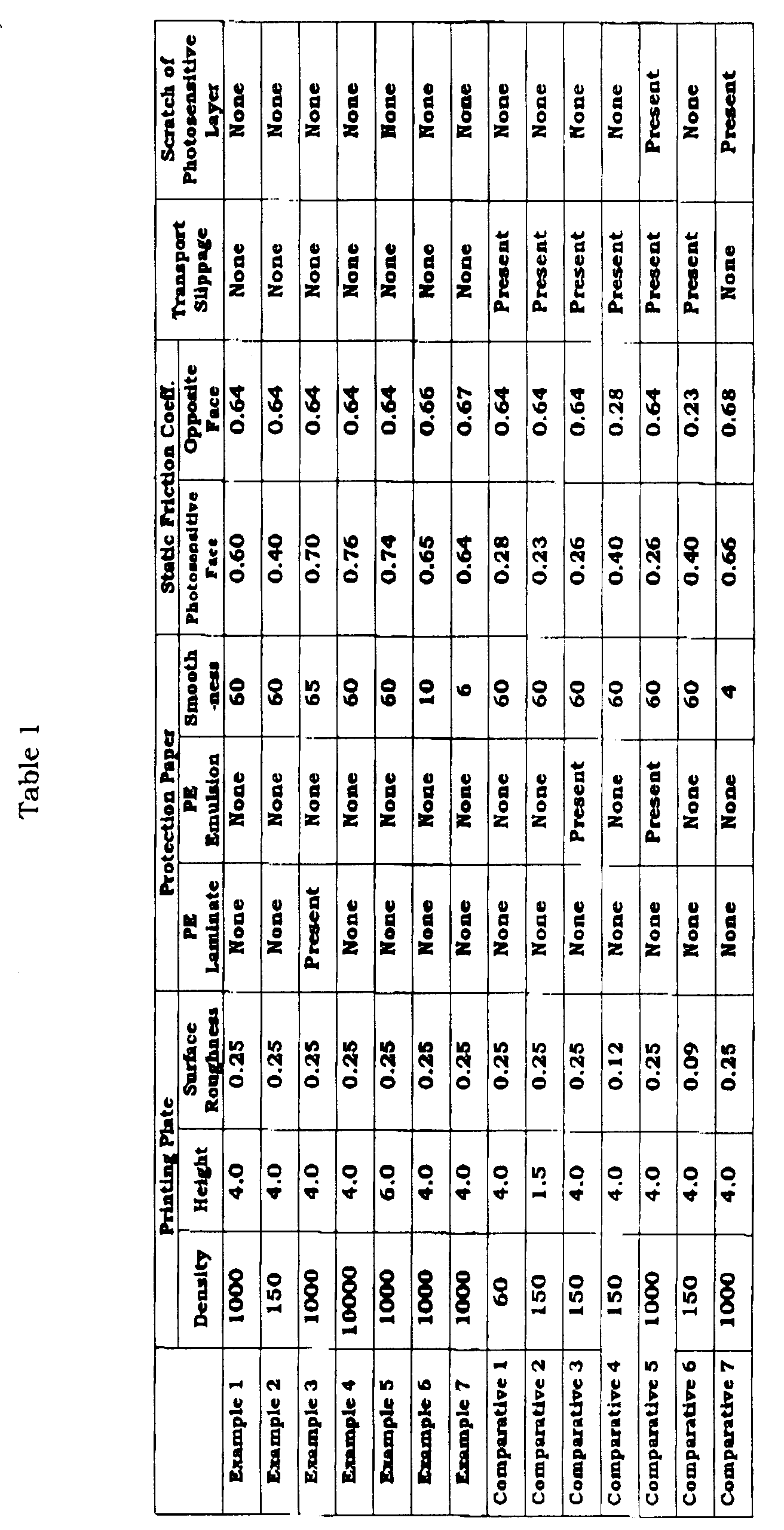
Claims (10)
- A package of photosensitive planographic printing plates which comprises a stack of the photosensitive planographic printing plates between each of which a protection paper is interposed, wherein the coefficient of static friction between the surface of the photosensitive layer of the photosensitive planographic printing plate and the surface of the protection paper is 0.3 or more.
- A package of photosensitive planographic printing plates which comprises a stack of the photosensitive planographic printing plates between each of which a protection paper is interposed, wherein the coefficient of static friction between the surface opposite to the photosensitive layer of the photosensitive planographic printing plate and the surface of the protection paper is 0.3 or more.
- The package of claim 1 wherein the coefficient of static friction between the surface opposite to the photosensitive layer of the photosensitive planographic printing plate and the surface of the protection paper is 0.3 or more.
- The package of claim 1 wherein a mat layer comprising convexes is formed on the photosensitive layer.
- The package of claim 4 wherein the convexes have a mean diameter of 200 µm or less, a mean height of 2 to 10 µm, and a density of 100 convexes/cm2 or more.
- The package of claim 5 wherein the density of the convexes is 700 convexes/cm2 or more.
- The package of claim 2 wherein the surface opposite to the photosensitive layer has a mean roughness of 0.15 or more.
- The package of claim 2 wehrein the surface opposite to the photosensitive layer has a mean roughness of 0.25 or more.
- A photosensitive planographic printing plate which comprises the photosensitive layer of which the surface is provided with convexes having a mean height of 2 µm or more a density of 100 convexes/cm2 or more, and the surface opposite to the photosensitive layer having a mean surface roughness of 0.15 or more.
- The photosensitive planographic printing plate of claim 9 wherein the convexes have a mean height of 2 to 10 µm and a density of 700 convexes/cm2 or more.
Applications Claiming Priority (3)
| Application Number | Priority Date | Filing Date | Title |
|---|---|---|---|
| JP27075497A JP4146917B2 (en) | 1997-10-03 | 1997-10-03 | Photosensitive lithographic printing plate package and photosensitive lithographic printing plate |
| JP27075497 | 1997-10-03 | ||
| JP270754/97 | 1997-10-03 |
Publications (3)
| Publication Number | Publication Date |
|---|---|
| EP0907107A2 true EP0907107A2 (en) | 1999-04-07 |
| EP0907107A3 EP0907107A3 (en) | 1999-07-21 |
| EP0907107B1 EP0907107B1 (en) | 2003-04-02 |
Family
ID=17490526
Family Applications (1)
| Application Number | Title | Priority Date | Filing Date |
|---|---|---|---|
| EP98118703A Expired - Lifetime EP0907107B1 (en) | 1997-10-03 | 1998-10-02 | Package of photosensitive planographic printing plates |
Country Status (4)
| Country | Link |
|---|---|
| US (1) | US6534234B1 (en) |
| EP (1) | EP0907107B1 (en) |
| JP (1) | JP4146917B2 (en) |
| DE (1) | DE69812824T2 (en) |
Cited By (5)
| Publication number | Priority date | Publication date | Assignee | Title |
|---|---|---|---|---|
| EP1136282A3 (en) * | 2000-03-03 | 2001-11-28 | Fuji Photo Film Co., Ltd. | Interleaf sheet for planographic printing plates, abutting member for planographic printing plates, and packaging structure for planographic printing plates |
| EP1160098A1 (en) * | 2000-06-01 | 2001-12-05 | Fuji Photo Film Co., Ltd. | Stacked planographic printing plates and stacking method for planographic printing plates |
| EP1190850A3 (en) * | 2000-09-20 | 2003-11-05 | Fuji Photo Film Co., Ltd. | Method for measuring strength of image forming surface of planographic printing plate, planographic printing plate and packaging structure for planographic printing plates |
| EP1963920A4 (en) * | 2005-12-21 | 2010-10-06 | Fujifilm Corp | Photosensitive sheets and method and apparatus for manufacturing the same |
| US8318405B2 (en) | 2009-03-13 | 2012-11-27 | Eastman Kodak Company | Negative-working imageable elements with overcoat |
Families Citing this family (13)
| Publication number | Priority date | Publication date | Assignee | Title |
|---|---|---|---|---|
| US20040154489A1 (en) * | 2000-05-08 | 2004-08-12 | Deutsch Albert S. | Chemical imaging of a lithographic printing plate |
| US6691618B2 (en) * | 2000-05-08 | 2004-02-17 | Pisces-Print Imaging Sciences, Inc. | Chemical imaging of a lithographic printing plate |
| JP2002059669A (en) * | 2000-08-16 | 2002-02-26 | Kodak Polychrome Graphics Japan Ltd | Insert for photosensitive lithographic printing plate |
| EP1312643B1 (en) * | 2000-08-23 | 2005-05-11 | National Institute of Advanced Industrial Science and Technology | Temperature-responsive polymer/polymer complex |
| JP2003320764A (en) * | 2002-02-27 | 2003-11-11 | Tokushu Paper Mfg Co Ltd | Lithographic paper for lithographic printing plate and method for producing the same |
| JP2009023354A (en) * | 2002-02-27 | 2009-02-05 | Tokushu Paper Mfg Co Ltd | Interleaf paper for lithographic printing |
| US7652115B2 (en) | 2003-09-08 | 2010-01-26 | 3M Innovative Properties Company | Fluorinated polyether isocyanate derived silane compositions |
| US7803894B2 (en) | 2003-12-05 | 2010-09-28 | 3M Innovatie Properties Company | Coating compositions with perfluoropolyetherisocyanate derived silane and alkoxysilanes |
| JP4621451B2 (en) * | 2004-08-11 | 2011-01-26 | 富士フイルム株式会社 | Protective film forming composition for immersion exposure and pattern forming method using the same |
| US7841186B2 (en) * | 2007-01-31 | 2010-11-30 | Power Systems Mfg., Llc | Inlet bleed heat and power augmentation for a gas turbine engine |
| US20100000898A1 (en) * | 2008-07-02 | 2010-01-07 | Johannes Bohn | Packaging assembly for printing plates |
| JP2011005873A (en) * | 2010-09-08 | 2011-01-13 | Kodak Japan Ltd | Interleaving paper for photosensitive lithographic printing plate |
| JP6735892B2 (en) * | 2018-12-13 | 2020-08-05 | 住友化学株式会社 | Package |
Family Cites Families (9)
| Publication number | Priority date | Publication date | Assignee | Title |
|---|---|---|---|---|
| US3897292A (en) * | 1972-08-18 | 1975-07-29 | Yamauchi Rubber Ind Co Ltd | Method of producing a printing magnetic saddle |
| JPS5629243A (en) * | 1979-08-15 | 1981-03-24 | Fuji Photo Film Co Ltd | Laminating method for photosensitive printing plate |
| JPS5799647A (en) * | 1980-12-11 | 1982-06-21 | Mitsubishi Chem Ind Ltd | Photosensitive lithographic printing plate material |
| JPS58137469A (en) * | 1982-02-10 | 1983-08-15 | Fuji Photo Film Co Ltd | Method of forming recording material into mat |
| EP0130222B1 (en) * | 1983-06-16 | 1988-05-25 | Toray Industries, Inc. | Cover film for printing plate |
| JPS6252548A (en) * | 1985-09-02 | 1987-03-07 | Fuji Photo Film Co Ltd | Photosensitive composition |
| JPH03249652A (en) * | 1990-02-27 | 1991-11-07 | Konica Corp | Lithographic printing plate material that does not require dampening water |
| DE69220433T2 (en) * | 1991-08-19 | 1997-10-16 | Fuji Photo Film Co Ltd | Presensitized plate for the production of a lithographic printing plate |
| JP2907643B2 (en) * | 1992-07-16 | 1999-06-21 | 富士写真フイルム株式会社 | Photosensitive lithographic printing plate and processing method thereof |
-
1997
- 1997-10-03 JP JP27075497A patent/JP4146917B2/en not_active Expired - Fee Related
-
1998
- 1998-10-02 EP EP98118703A patent/EP0907107B1/en not_active Expired - Lifetime
- 1998-10-02 DE DE69812824T patent/DE69812824T2/en not_active Expired - Lifetime
- 1998-10-05 US US09/166,183 patent/US6534234B1/en not_active Expired - Lifetime
Cited By (8)
| Publication number | Priority date | Publication date | Assignee | Title |
|---|---|---|---|---|
| EP1136282A3 (en) * | 2000-03-03 | 2001-11-28 | Fuji Photo Film Co., Ltd. | Interleaf sheet for planographic printing plates, abutting member for planographic printing plates, and packaging structure for planographic printing plates |
| US6551696B2 (en) | 2000-03-03 | 2003-04-22 | Fuji Photo Film Co., Ltd. | Interleaf sheet for planographic printing plates, abutting member for planographic printing plates, and packaging structure for planographic printing plates |
| EP1160098A1 (en) * | 2000-06-01 | 2001-12-05 | Fuji Photo Film Co., Ltd. | Stacked planographic printing plates and stacking method for planographic printing plates |
| EP1190850A3 (en) * | 2000-09-20 | 2003-11-05 | Fuji Photo Film Co., Ltd. | Method for measuring strength of image forming surface of planographic printing plate, planographic printing plate and packaging structure for planographic printing plates |
| US6732864B2 (en) | 2000-09-20 | 2004-05-11 | Fuji Photo Film Co., Ltd. | Method for measuring strength of image forming surface of planographic printing plate, planographic printing plate and packaging structure for planographic printing plates |
| EP1963920A4 (en) * | 2005-12-21 | 2010-10-06 | Fujifilm Corp | Photosensitive sheets and method and apparatus for manufacturing the same |
| US8124316B2 (en) | 2005-12-21 | 2012-02-28 | Fujifilm Corporation | Photosensitive sheets and method and apparatus for manufacturing the same |
| US8318405B2 (en) | 2009-03-13 | 2012-11-27 | Eastman Kodak Company | Negative-working imageable elements with overcoat |
Also Published As
| Publication number | Publication date |
|---|---|
| DE69812824T2 (en) | 2003-11-06 |
| DE69812824D1 (en) | 2003-05-08 |
| JP4146917B2 (en) | 2008-09-10 |
| EP0907107B1 (en) | 2003-04-02 |
| US6534234B1 (en) | 2003-03-18 |
| JPH11109611A (en) | 1999-04-23 |
| EP0907107A3 (en) | 1999-07-21 |
Similar Documents
| Publication | Publication Date | Title |
|---|---|---|
| EP0907107B1 (en) | Package of photosensitive planographic printing plates | |
| US5464724A (en) | PS plate and method for processing same | |
| US5496677A (en) | Presensitized plate for use in making lithographic printing plate comprising a mat layer and coating layer on the back face of the substrate | |
| EP0595179B1 (en) | Method for preparing an aluminum substrate for lithographic printing plate | |
| JP2739395B2 (en) | Photosensitive lithographic printing plate | |
| EP0730979B1 (en) | Support for lithographic printing plate, process for the preparation thereof and electrochemical roughening apparatus | |
| GB2276729A (en) | Developers and replenishers for presensitised plates | |
| JP2005062456A (en) | Ir ray photosensitive planographic printing plate | |
| EP0487343B1 (en) | Process for preparing a lithographic plate | |
| EP1834802A1 (en) | Infrared-sensitive lithographic printing plate | |
| JP3830270B2 (en) | Photosensitive lithographic printing plate and method for producing the same | |
| JPH06332155A (en) | Photosensitive planographic printing plate | |
| JP2967009B2 (en) | Photosensitive lithographic printing plate | |
| EP0511659A1 (en) | Method for processing photosensitive copying materials | |
| JP3388873B2 (en) | Method for electrolytic treatment of strip-shaped metal plate, method for producing lithographic printing plate support, and method for producing photosensitive lithographic printing plate | |
| JPH06230563A (en) | Photosensitive planographic printing plate and production of planographic printing plate | |
| US5873771A (en) | Process for manufacturing lithographic printing plate support | |
| JP3738920B2 (en) | Positive photosensitive lithographic printing plate | |
| EP0841190A1 (en) | Lithographic printing plate | |
| JPH06324477A (en) | Photosensitive planographic printing plate | |
| JPH06247070A (en) | Aluminum support for lithographic printing block | |
| JPH1090905A (en) | Manufacture of lithographic plate support body | |
| JP2002234272A (en) | Packaging material for lithographic plate and packaging structure of lithographic plate | |
| JPH06234285A (en) | Production of photosensitive lithographic plate | |
| JP2001335998A (en) | Aluminum supporting body and roughening method therefor |
Legal Events
| Date | Code | Title | Description |
|---|---|---|---|
| PUAI | Public reference made under article 153(3) epc to a published international application that has entered the european phase |
Free format text: ORIGINAL CODE: 0009012 |
|
| AK | Designated contracting states |
Kind code of ref document: A2 Designated state(s): DE |
|
| AX | Request for extension of the european patent |
Free format text: AL;LT;LV;MK;RO;SI |
|
| PUAL | Search report despatched |
Free format text: ORIGINAL CODE: 0009013 |
|
| AK | Designated contracting states |
Kind code of ref document: A3 Designated state(s): AT BE CH CY DE DK ES FI FR GB GR IE IT LI LU MC NL PT SE |
|
| AX | Request for extension of the european patent |
Free format text: AL;LT;LV;MK;RO;SI |
|
| RIC1 | Information provided on ipc code assigned before grant |
Free format text: 6G 03F 7/00 A, 6G 03F 7/09 B, 6G 03F 7/115 B |
|
| 17P | Request for examination filed |
Effective date: 20000110 |
|
| AKX | Designation fees paid |
Free format text: DE |
|
| 17Q | First examination report despatched |
Effective date: 20020213 |
|
| GRAH | Despatch of communication of intention to grant a patent |
Free format text: ORIGINAL CODE: EPIDOS IGRA |
|
| RTI1 | Title (correction) |
Free format text: PACKAGE OF PHOTOSENSITIVE PLANOGRAPHIC PRINTING PLATES |
|
| GRAH | Despatch of communication of intention to grant a patent |
Free format text: ORIGINAL CODE: EPIDOS IGRA |
|
| GRAA | (expected) grant |
Free format text: ORIGINAL CODE: 0009210 |
|
| AK | Designated contracting states |
Designated state(s): DE |
|
| REF | Corresponds to: |
Ref document number: 69812824 Country of ref document: DE Date of ref document: 20030508 Kind code of ref document: P |
|
| PLBE | No opposition filed within time limit |
Free format text: ORIGINAL CODE: 0009261 |
|
| STAA | Information on the status of an ep patent application or granted ep patent |
Free format text: STATUS: NO OPPOSITION FILED WITHIN TIME LIMIT |
|
| 26N | No opposition filed |
Effective date: 20040105 |
|
| PGFP | Annual fee paid to national office [announced via postgrant information from national office to epo] |
Ref country code: DE Payment date: 20140923 Year of fee payment: 17 |
|
| REG | Reference to a national code |
Ref country code: DE Ref legal event code: R119 Ref document number: 69812824 Country of ref document: DE |
|
| PG25 | Lapsed in a contracting state [announced via postgrant information from national office to epo] |
Ref country code: DE Free format text: LAPSE BECAUSE OF NON-PAYMENT OF DUE FEES Effective date: 20160503 |