EP0907037B1 - Suspension damper polygonal reservoir tube - Google Patents
Suspension damper polygonal reservoir tube Download PDFInfo
- Publication number
- EP0907037B1 EP0907037B1 EP98202917A EP98202917A EP0907037B1 EP 0907037 B1 EP0907037 B1 EP 0907037B1 EP 98202917 A EP98202917 A EP 98202917A EP 98202917 A EP98202917 A EP 98202917A EP 0907037 B1 EP0907037 B1 EP 0907037B1
- Authority
- EP
- European Patent Office
- Prior art keywords
- tube
- section
- reservoir
- reservoir tube
- polygonal
- Prior art date
- Legal status (The legal status is an assumption and is not a legal conclusion. Google has not performed a legal analysis and makes no representation as to the accuracy of the status listed.)
- Expired - Lifetime
Links
Images


Classifications
-
- B—PERFORMING OPERATIONS; TRANSPORTING
- B60—VEHICLES IN GENERAL
- B60G—VEHICLE SUSPENSION ARRANGEMENTS
- B60G15/00—Resilient suspensions characterised by arrangement, location or type of combined spring and vibration damper, e.g. telescopic type
- B60G15/02—Resilient suspensions characterised by arrangement, location or type of combined spring and vibration damper, e.g. telescopic type having mechanical spring
- B60G15/06—Resilient suspensions characterised by arrangement, location or type of combined spring and vibration damper, e.g. telescopic type having mechanical spring and fluid damper
- B60G15/067—Resilient suspensions characterised by arrangement, location or type of combined spring and vibration damper, e.g. telescopic type having mechanical spring and fluid damper characterised by the mounting on the vehicle body or chassis of the spring and damper unit
- B60G15/068—Resilient suspensions characterised by arrangement, location or type of combined spring and vibration damper, e.g. telescopic type having mechanical spring and fluid damper characterised by the mounting on the vehicle body or chassis of the spring and damper unit specially adapted for MacPherson strut-type suspension
-
- F—MECHANICAL ENGINEERING; LIGHTING; HEATING; WEAPONS; BLASTING
- F16—ENGINEERING ELEMENTS AND UNITS; GENERAL MEASURES FOR PRODUCING AND MAINTAINING EFFECTIVE FUNCTIONING OF MACHINES OR INSTALLATIONS; THERMAL INSULATION IN GENERAL
- F16F—SPRINGS; SHOCK-ABSORBERS; MEANS FOR DAMPING VIBRATION
- F16F9/00—Springs, vibration-dampers, shock-absorbers, or similarly-constructed movement-dampers using a fluid or the equivalent as damping medium
- F16F9/32—Details
- F16F9/3207—Constructional features
- F16F9/3235—Constructional features of cylinders
-
- B—PERFORMING OPERATIONS; TRANSPORTING
- B60—VEHICLES IN GENERAL
- B60G—VEHICLE SUSPENSION ARRANGEMENTS
- B60G2206/00—Indexing codes related to the manufacturing of suspensions: constructional features, the materials used, procedures or tools
- B60G2206/01—Constructional features of suspension elements, e.g. arms, dampers, springs
- B60G2206/40—Constructional features of dampers and/or springs
- B60G2206/41—Dampers
-
- B—PERFORMING OPERATIONS; TRANSPORTING
- B60—VEHICLES IN GENERAL
- B60G—VEHICLE SUSPENSION ARRANGEMENTS
- B60G2206/00—Indexing codes related to the manufacturing of suspensions: constructional features, the materials used, procedures or tools
- B60G2206/01—Constructional features of suspension elements, e.g. arms, dampers, springs
- B60G2206/40—Constructional features of dampers and/or springs
- B60G2206/42—Springs
- B60G2206/422—Accumulators for hydropneumatic springs
-
- B—PERFORMING OPERATIONS; TRANSPORTING
- B60—VEHICLES IN GENERAL
- B60G—VEHICLE SUSPENSION ARRANGEMENTS
- B60G2206/00—Indexing codes related to the manufacturing of suspensions: constructional features, the materials used, procedures or tools
- B60G2206/01—Constructional features of suspension elements, e.g. arms, dampers, springs
- B60G2206/80—Manufacturing procedures
- B60G2206/81—Shaping
Definitions
- the present invention relates to a suspension damper with a polygonal reservoir tube.
- shock absorbers typically consist of direct double-acting telescopic hydraulic dampers and are generally described as either shock absorbers or struts. This basic arrangement has been successfully used for well over half a century.
- a primary purpose of shock absorbers is to dampen oscillations of the vehicle's suspension springs. This is accomplished by converting kinetic energy in the form of motion between the sprung and unsprung masses of the vehicle into heat and then dissipating the heat.
- Struts also serve this capacity and in addition, act as a structural member to support reaction and side load forces on the suspension system.
- Twin-tube dampers that provide a reservoir between the cylinder tube and a reservoir tube are well known.
- a circular cylindrical reservoir tube having a closed bottom portion is generally provided.
- the top end of the circular cylindrical tube generally includes an opening through which the piston rod extends, and is typically provided with a means of sealing the area of the opening around the piston rod.
- Various techniques are presently used to close the ends of the circular cylindrical tubular sections for suspension dampers. One method is to weld a bottom closure to the tube. Another involves roll forming the wall of the tube to produce an integral closure.
- Suspension dampers have evolved over the years, with the valving and rod guide components taking innumerable configurations and present day dampers are known in passive, adaptive, semi-active and active forms. Over the same period, the cylinder tube and, in the case of twin-tube damper, the cylinder tube and the reservoir tube, have remained steadfastly unchanged.
- US Patent 5,638,927 issued June 17, 1997 and likewise shows a suspension damper with circular cylindrical cylinder and reservoir tubes.
- GB 1491251 discloses a suspension damper having a flexible plastic reservoir tube having axially directed corrugations to render the reservoir tube radially expandable and contractible to accommodate the varying volumes of hydraulic fluid retained therein.
- the damper is contained within a tubular support member having a stub axle mounted thereon. Accordingly, it appears the art has determined that circular cylindrical cylinder and reservoir tubes are optimal.
- damper tubes are produced from roll formed sheet metal stock with welded mating edges, although the tube can also be impacted, drawn or extruded into a circular cylindrical form.
- operational reciprocation of the piston within the cylinder tube results in some flexure induced rotation of the piston relative to the cylinder tube. Accordingly, the circular cylindrical shape advantageously accommodates the real world conditions.
- a conventional damper may suffer undesirable oil starvation conditions. This can be complicated by a typical 10-15% oil loss over the extended life of an original equipment damper.
- oil is drawn into the working cylinder from the reservoir. Under starvation conditions, air may be drawn in along with the oil resulting in problematic cavitation conditions. Accordingly, a sufficiently large sized reservoir must be provided to avoid these conditions. Often the need to provide a larger reservoir conflicts with packaging constraints placed on the damper by the application. This leads to a need for greater flexibility in designing dampers for given application than is presently available.
- the present invention utilizes a reservoir tube with a polygonal cross sectional shape.
- the increase in the moment of inertia enables greater design flexibility. For example, thinner tube wall sections are possible, resulting in desirable material and weight savings. Additionally, reduced outside lateral dimensions are possible for improved packageability. As another advantage, flat reservoir surfaces facilitate bracket mounting. Further, improved fatigue and stiffness properties can be achieved through proliferated cross sectional characteristic choices.
- a preferred embodiment of the present invention includes a piston that is reciprocally carried in a circular cylindrical cylinder tube.
- the piston is attached to a piston rod that extends out from the cylinder tube and is adapted for connection to one of the sprung or unsprung masses of an associated vehicle.
- the circular cylindrical cylinder tube is carried in a reservoir tube that is adapted for connection to the other of the sprung and unsprung masses.
- the reservoir tube includes a mid-section with a polygonal cross section and includes an open end with a circular cross section. The open end is closed by a rod guide assembly that engages the reservoir tube and the cylinder tube.
- the reservoir tube includes a closed end opposite the open end that is optionally polygonal or circular in configuration.
- a mounting bracket is utilized near the closed end of the reservoir tube and is engaged around the polygonal cross sectional part of the tube.
- the reservoir tube carries a spring seat that is engaged with the reservoir tube and is fixed around the polygonal cross sectional part of the tube.
- a McPherson strut assembly 10 that includes a twin-tube type damper assembly 11.
- Damper assembly 11 has an elongated reservoir tube 12 with an integrally formed closed end 14 and an open end 15.
- An elongated cylinder tube 16 is axially disposed within the reservoir tube 12 and has a consistent circular cross section.
- a reservoir 24 is defined between the reservoir tube 12 and the cylinder tube 16.
- a circular disk-like base valve assembly 17 is carried within the end 18 of cylinder tube 16, and the end 19 of cylinder tube 16 is secured on an annular rod guide assembly 20.
- the cylinder tube 16 slidably supports a piston assembly 21 that separates the cylinder tube into compression chamber 22 and extension chamber 23.
- the compression chamber 22, extension chamber 23 and reservoir 24 carry a supply of fluid that operates as the damping medium within the damper assembly 11.
- Piston assembly 21 is connected to a piston rod 25 that extends through the extension chamber 23 and exits the damper assembly 11 through rod guide assembly 20, engaging seal 26 and extending from the open end 15 of reservoir tube 12.
- the open end 15 is partially closed over the rod guide assembly 20 thereby securing the rod guide assembly 20 in place, and a seal cover 27 is positioned over the open end 15.
- the piston rod 25 includes a threaded end 28 that is adapted to be secured to the sprung mass of an associated vehicle (not illustrated), and a mounting bracket 29 is provided near the closed end 14 of reservoir tube 12 for connection to the unsprung mass of the associated vehicle.
- the piston assembly 21 is caused to reciprocally move within the cylinder tube 16 as the piston rod 25 enters and exits the damper assembly 11 through the rod guide assembly 20. Sliding movement of the piston assembly 21 within the cylinder tube 16 is inhibited by the action of fluid resistance which is caused to be generated by the restriction of fluid flow through the valving of piston assembly 21.
- fluid travels between the compression chamber 22 and the extension chamber 23.
- the piston rod occupies a variable volumetric amount of the available area within the damper assembly 11, fluid is caused to flow through the base valve assembly 17 between the compression chamber 22 and the reservoir 24. Accordingly, the reservoir 24 must be sufficiently large to accommodate the varying fluid level, in addition to a compressible gas space that is optionally maintained within the reservoir 24 near the rod guide assembly 20.
- the space occupied by the strut 10 is typically at a premium since the adjacent components of the vehicle's suspension system operate in very close proximity. Accordingly, damper engineers are often faced with strict packaging limitations in the design of products for given applications. These space limitations often conflict with a desire to maximize the size of the strut's reservoir. Maximizing the size of the reservoir is advantageous for a variety of reasons. First, a larger reservoir ensures that an adequate supply of oil is available for optimum strut operation. For example, if insufficient oil is available, the strut's valving may suffer from oil starvation. This can occur during extension operation when oil is drawn into the cylinder tube from the reservoir.
- a larger reservoir ensures that the oil supply is adequately housed in the reservoir during compression of the strut, and enables maximizing the size of the piston rod without overloading the reservoir.
- a problem faced when addressing these concerns is that increasing the size of the reservoir is accompanied by a packaging penalty.
- the present embodiment of the invention includes a reservoir tube 12 with a mid-section 30 having a polygonal cross section as shown in the Figure 2.
- a square cross section is utilized that enables reducing the distance in the cross-car direction between sides 31 and 32 as compared to a round tube, while providing sufficiently large volume within the open area 33 to provide the fluid storage requirements for the strut 10.
- the square shape of mid-section 30 extends from a first square-to-round transition 34, to a second square-to-round transition 35.
- a spring seat 38 is provided for supporting a coil spring (not illustrated) upon which the sprung mass of the vehicle rests.
- Spring seat 38 includes a square opening 39 that is secured over the mid-section 30 adjacent the square-to-round transition 35 by typical a means such as welding.
- the mounting bracket 29 is secured on the reservoir tube 12 at the square mid-section 30 and adjacent the square-to-round transition 34, greatly simplifying proper orientation relative to the spring seat 38 and the strut 10.
- the mounting bracket 29 includes a body 40 with a semi-square U-shaped opening 41 that receives the reservoir tube 12.
- the reservoir tube 12 is secured in position by a plate 42 that is fixed to the body 40 by a plurality of fasteners 43 clamping the damper 11 within the mounting bracket 29.
- I ⁇ / 64 ( D 4 - d 4 )
- D the outside diameter of the tube
- d the inside diameter of the tube.
- strut 45 similarly has a reservoir tube 46 with a mid-section 47 having a square cross-sectional shape as shown in Figure 4.
- the strut 45 also has a circular cylindrical cylinder tube 48 that slidably carries piston assembly 49.
- Reservoir tube 46 includes a square-to-round transition 50 with the upper section 51 having a circular cross section for mating with annular rod guide assembly 52.
- the closed end 53 of reservoir tube 46 remains square in shape and can be integrally formed with the wall of reservoir tube 46 or is preferably provided as a separate welded-on piece.
- Strut 45 includes a mounting bracket 54 with a body 55 that exhibits a semi-square U-shaped opening 56 as seen in Figure 4, which receives the square section of reservoir tube 46.
- a pair of braces 57 and 58 are fixed to the mounting bracket body 55 by a plurality of fasteners 59 clamping the mounting bracket 54 to the reservoir tube 46.
- strut assembly 60 is illustrated as a packaged unit including top-mount assembly 61, coil spring 62, jounce bumper 63, dust cover 64, mounting bracket 65, spring seat 66 and damper assembly 67.
- the strut assembly 60 is of the turnable type for use at the front corner of a vehicle, and is designed to operate as a damping device in the vehicle's suspension, while carrying both lateral and longitudinal forces that are transmitted through the suspension system.
- the damper assembly 67 includes a reservoir tube 68 having a mid-section 69 with a rectangular cross section as seen in Figure 7.
- the reservoir tube 68 also includes a rectangular-to-round transition 70 with a circular upper section 71 and a rectangular-to-round transition 72 with a circular-shaped closed end 73.
- Selection of a rectangular shape provides a relatively thin outside dimension between the sides 75 and 76 so that the mid-section 69 occupies relatively little space and is preferably oriented with the short side of the rectangle in the cross-car direction.
- the long side of the rectangular cross section is preferably provided in the longitudinal vehicle direction.
- the mounting bracket 65 is relatively simply formed with a semi-squared shaped opening that is received over the reservoir tube 68 and is secured thereon by a weld bead 77.
- the reservoir tube 68 carries a circular cylindrical cylinder tube 74 so that the sides 75 and 76 of the reservoir tube 68 are positioned relatively close to the cylinder tube 74.
- the sides 78 and 79 (as seen in Figure 7), at the ends of the long side of the rectangular shape, provide sufficient distance from the cylinder tube 74 to ensure that an adequately large reservoir volume is provided.
- FIG. 6 a schematic representation of the cross section of the reservoir tube 12 of strut 10 as shown in Figure 1, and the reservoir tube 46 of strut 45 as shown in Figure 3, is illustrated.
- Figure 7 a schematic representation of the rectangular cross section of the reservoir tube 68 of strut assembly 60 as shown in Figure 5 is illustrated.
- Figure 8 a schematic representation of the cross section of a reservoir tube according to another embodiment of the present invention is illustrated.
- the reservoir tube 80 is provided in a trapezoidal shape and provides a further alternative to the square shape of the reservoir tube of Figure 6 and the rectangular shape of the reservoir tube of Figure 7.
- the square mid-section 30 of reservoir tube 12 is formed from a preliminarily round tube which corresponds to the upper section 36.
- the distance across the square mid-section 30 is 45 millimeters in the present embodiment, which is developed from the same perimeter as the upper section 36 which has an inside diameter of 50 millimeters and a wall thickness of two millimeters.
- the corners 81 of the mid-section 30 each have a radius of approximately 6.35 millimeters.
- the die 82 comprises an upper die section 83 and a lower die section 84 that are adapted to be connected to opposed platens of a press (not illustrated).
- a 41 millimeter square mandrel 85 is inserted into the tube 12A.
- Mandrel 85 includes rounded corners 86 that lie on a 50 millimeter diameter across the mandrel.
- Tube 12A has an inside diameter of 50 millimeters and an outside diameter of 54 millimeters with a consistent wall thickness of 2 millimeters.
- a key consideration in the squaring process is the redistribution of tube material without creating a positive or negative wall thickness result, while moving material to form the new shape. Therefore, upon initial closure of the upper and lower die sections 83 and 84 onto the tube 12A as supported by the mandrel 85, tangents 87 and 88 and two similar tangents (not visible) around the tube 12A are contacted. The tangents 87 and 88 are substantially centered across the flats 89 and 90 of the mandrel 85. This initial contact allocates the material of tube 12A to four quadrants in order to form corners from the round tube without pushing material around the corners. As the tube material at the tangents is moved toward the mandrel 85, the material adjacent the rounded corners 86 pulls away from the mandrel 85 to form the corners of the polygonal shape.
- the bottom die section 84 includes a wrapped leg 92 which extends around the corner 93, and a similar leg on the opposite side of the tube 12A.
- the four tangent points including tangents 87 and 88, are placed at 45 degrees offset from the horizontal and vertical. The offset tangent points apply a symmetrical load to the tube 12A forcing material to be evenly distributed around the mandrel 85 and within the cavity 91 of upper die 83, and the cavity 94 of lower die 84.
- the material of the tube 12A uniformly fills the cavities 91 and 94 as the die 82 closes. This process ensures the uniform reshaping (redistribution) of the round tube material while minimizing internal stresses within the material.
- the tube 12A is initially contacted at the tangents, with a uniform load applied until restrained by the center support mandrel 85. This allows each straight segment of square tubing to be formed from its immediately closest round tube section. The corners are formed from the nearest available material minimizing the possibility of tube ruptures. Extending the leg 92 of lower die section 84 around the tube 12A at the parting line 95 traps the material at the corner 93 preventing the formation of a pinch point as the die 82 closes.
- the resultant reservoir tube 12 is illustrated in perspective with the square shape to mid-section 30 shown as formed in the die 82.
- the round integral bottom closure at closed end 14 and the round upper section 36 remain unreformed.
- the selected location of the square-to-round transitions is determined by the amount of the round section of the tube 12A that is permitted to extend from the ends of cavities 91,94 and can be completely omitted if preferred.
- FIG 12 the formation of a rectangular tube section from a round tube is illustrated schematically.
- a rectangular mid-section 69 having outside dimensions across its sides of 55 millimeters and 45 millimeters with corner radii of approximately 6.35 millimeters is formed from a round tube section having an outside diameter of 60 millimeters with a 2 millimeter thick wall.
- the 60 millimeter diameter round section remains at the upper section 71.
- a round tube 69A is supported on a 45 millimeter x 51 millimeter mandrel 96, having rounded corners 97 that match the 56 millimeter inside diameter of tube 69A.
- a die 98 having an upper die section 99 and a lower die section 100 includes an upper die cavity 110 and a lower die cavity 101 that together define an elongated opening with a cross section 45 millimeters x 55 millimeters having 6.35 millimeter rounded corners, when the die sections 99 and 100 are closed at the parting line 102.
- the distance the material of rounded tube 69A must be moved to produce the rectangular shape is different than the distance required to form a uniformly square-shaped tube.
- the contact points 103 and 104 for the material that must move the furthest distance make contact first, initially producing an oval shape from the tube 69A.
- the lower die section 100 includes legs 105 and 106 that wrap around the corners 107 and 108 to prevent pinching of material from the tube 69A in the part line 102.
- the material of the tube 69A separates from the rounded corners 97, initially at opposite ends of adjacent rounded corners and next to the short sides of the rectangular-shaped mandrel 96.
- the rectangular shape of the tube 69 is formed, with voids 109 opened between the tube 69 and the rounded corners 97 of the mandrel 96.
- Uniform thickness of the tube 69 is maintained across the flat sides by compression of the tube between the flat sides of the mandrel and the planar sides of the die cavities. The process accumulates any added thickness at the corners of the tube 69 adjacent the voids 109 since the corners are formed last with material length being pushed to the corner due to clearance between the inside of the tube and the mandrel adjacent voids 109.
- the present invention provides a vehicle suspension damper with a polygonal reservoir tube that solves the problem of packaging a shock or a strut into a limited space environment. Additionally, strength and fluid storage improvements allow enhanced design freedom in applying dampers to new applications.
Landscapes
- Engineering & Computer Science (AREA)
- General Engineering & Computer Science (AREA)
- Mechanical Engineering (AREA)
- Fluid-Damping Devices (AREA)
Description
- The present invention relates to a suspension damper with a polygonal reservoir tube.
- Conventional vehicle suspension dampers typically consist of direct double-acting telescopic hydraulic dampers and are generally described as either shock absorbers or struts. This basic arrangement has been successfully used for well over half a century. A primary purpose of shock absorbers is to dampen oscillations of the vehicle's suspension springs. This is accomplished by converting kinetic energy in the form of motion between the sprung and unsprung masses of the vehicle into heat and then dissipating the heat. Struts also serve this capacity and in addition, act as a structural member to support reaction and side load forces on the suspension system.
- Twin-tube dampers that provide a reservoir between the cylinder tube and a reservoir tube are well known. To house the twin-tube damper, a circular cylindrical reservoir tube having a closed bottom portion is generally provided. The top end of the circular cylindrical tube generally includes an opening through which the piston rod extends, and is typically provided with a means of sealing the area of the opening around the piston rod. Various techniques are presently used to close the ends of the circular cylindrical tubular sections for suspension dampers. One method is to weld a bottom closure to the tube. Another involves roll forming the wall of the tube to produce an integral closure.
- Suspension dampers have evolved over the years, with the valving and rod guide components taking innumerable configurations and present day dampers are known in passive, adaptive, semi-active and active forms. Over the same period, the cylinder tube and, in the case of twin-tube damper, the cylinder tube and the reservoir tube, have remained steadfastly unchanged. For example, US Patent 2,025,199 issued December 24, 1935. That patent shows a direct acting shock absorber with a cylinder comprising "concentric" circular tubular members. US Patent 5,638,927 issued June 17, 1997 and likewise shows a suspension damper with circular cylindrical cylinder and reservoir tubes. GB 1491251 discloses a suspension damper having a flexible plastic reservoir tube having axially directed corrugations to render the reservoir tube radially expandable and contractible to accommodate the varying volumes of hydraulic fluid retained therein. The damper is contained within a tubular support member having a stub axle mounted thereon. Accordingly, it appears the art has determined that circular cylindrical cylinder and reservoir tubes are optimal.
- It is known that the bending moment of inertia for a circular cylindrical reservoir tube of a certain thickness is defined by the equation: I = π / 64 (D 4-d 4), where D is the outside diameter of the tube, and d is the inside diameter of the tube. This bending moment of inertia defines the resistance to bending of the tube of a circular cross section about its center axis. The bending moment of inertia is an important concept since it defines the damper's ability to withstand operational induced stresses.
- Typically, damper tubes are produced from roll formed sheet metal stock with welded mating edges, although the tube can also be impacted, drawn or extruded into a circular cylindrical form. This produces a convenient reservoir structure to facilitate end closure and for receiving the circular cylindrical cylinder tube. Since the top and/or bottom end closures are typically rolled closed, the circular cylindrical shape is advantageous. Typically, operational reciprocation of the piston within the cylinder tube results in some flexure induced rotation of the piston relative to the cylinder tube. Accordingly, the circular cylindrical shape advantageously accommodates the real world conditions.
- Depending in piston rod size and reservoir size, a conventional damper may suffer undesirable oil starvation conditions. This can be complicated by a typical 10-15% oil loss over the extended life of an original equipment damper. During an extension cycle of a damper, oil is drawn into the working cylinder from the reservoir. Under starvation conditions, air may be drawn in along with the oil resulting in problematic cavitation conditions. Accordingly, a sufficiently large sized reservoir must be provided to avoid these conditions. Often the need to provide a larger reservoir conflicts with packaging constraints placed on the damper by the application. This leads to a need for greater flexibility in designing dampers for given application than is presently available.
- Accordingly to the present invention there is provided a suspension damper as claimed in claim 1. Rather than maintaining a circular cylindrical reservoir tube, the present invention utilizes a reservoir tube with a polygonal cross sectional shape. In the case of an optional square polygonal shape, the invention results in a reservoir tube with a bending moment of inertia defined by the equation: I = 1 / 12 (H 4 - h 4), where H is the distance across the outside of the tube and h is the distance across the inside of the tube. By changing from a round to a square shaped polygonal cross section reservoir tube, the bending moment of inertia for comparable wall thickness reservoir tubes is defined by the ratio Isquare / Icircular or 1.69:1. In the case of an optional rectangular polygonal shape, the invention results in a reservoir tube with a bending moment of inertia defined by the equation: I = 1 / 12 (BH 3 -gh 3), where B is the outside dimension of the long side of the rectangular cross section of the tube, h is the outside dimension of the short side of the rectangular cross section of the tube,, b is the inside dimension of the long side of the rectangular cross section of the tube, and h is the inside dimension of the short side of the rectangular cross section of the tube.
- According to a preferred aspect of the present invention, the increase in the moment of inertia enables greater design flexibility. For example, thinner tube wall sections are possible, resulting in desirable material and weight savings. Additionally, reduced outside lateral dimensions are possible for improved packageability. As another advantage, flat reservoir surfaces facilitate bracket mounting. Further, improved fatigue and stiffness properties can be achieved through proliferated cross sectional characteristic choices.
- A preferred embodiment of the present invention includes a piston that is reciprocally carried in a circular cylindrical cylinder tube. The piston is attached to a piston rod that extends out from the cylinder tube and is adapted for connection to one of the sprung or unsprung masses of an associated vehicle. The circular cylindrical cylinder tube is carried in a reservoir tube that is adapted for connection to the other of the sprung and unsprung masses. The reservoir tube includes a mid-section with a polygonal cross section and includes an open end with a circular cross section. The open end is closed by a rod guide assembly that engages the reservoir tube and the cylinder tube. The reservoir tube includes a closed end opposite the open end that is optionally polygonal or circular in configuration. According to a preferred aspect of the present invention, a mounting bracket is utilized near the closed end of the reservoir tube and is engaged around the polygonal cross sectional part of the tube. According to another preferred aspect of the present invention, the reservoir tube carries a spring seat that is engaged with the reservoir tube and is fixed around the polygonal cross sectional part of the tube.
- The present invention will now be described, by way of example, with reference to the accompanying drawings , in which:-
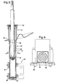
- Figure 1 is a fragmentary cross sectional illustration of a suspension damper according to the present invention.
- Figure 2 is a cross sectional illustration taken generally through the plane indicated by the line 2-2 in Figure 1.
- Figure 3 is a fragmentary cross sectional illustration of a suspension damper according to the present invention.
- Figure 4 is a cross sectional illustration taken generally through the plane indicated by the line 4-4 in Figure 3.
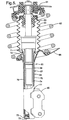
- Figure 5 is a is a fragmentary cross sectional illustration of a suspension damper according to the present invention.
- Figure 6 is an exemplary polygonal cross section of a reservoir tube according to the present invention that can be used with the dampers of Figures 1, 3 and 5.
- Figure 7 is an exemplary polygonal cross section of a reservoir tube according to the present invention that can be used with the dampers of Figures 1, 3 and 5.
- Figure 8 is an exemplary polygonal cross section of a reservoir tube according to the present invention that can be used with the dampers of Figures 1, 3 and 5.
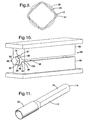
- Figure 9 is a schematic illustration showing a round-to-square tube formation relationship.
- Figure 10 is a round-to-square tube forming device.
- Figure 11 is a perspective illustration of the reservoir tube of the suspension damper shown in Figure 1.
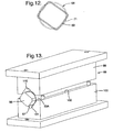
- Figure 12 is a schematic illustration showing a round-to-rectangular tube formation relationship.
- Figure 13 is a round-to-rectangular tube forming device.
- Figure 14 is a stage of a round-to-rectangular tube forming operation.
- Figure 15 is a stage of a round-to-rectangular tube forming operation.
- Figure 16 is a stage of a round-to-rectangular tube forming operation.
-
- Referring to the drawings, illustrated in Figure 1 is a
McPherson strut assembly 10 that includes a twin-tubetype damper assembly 11.Damper assembly 11 has an elongatedreservoir tube 12 with an integrally formedclosed end 14 and anopen end 15. Anelongated cylinder tube 16 is axially disposed within thereservoir tube 12 and has a consistent circular cross section. Areservoir 24 is defined between thereservoir tube 12 and thecylinder tube 16. A circular disk-likebase valve assembly 17 is carried within theend 18 ofcylinder tube 16, and theend 19 ofcylinder tube 16 is secured on an annularrod guide assembly 20. - The
cylinder tube 16 slidably supports apiston assembly 21 that separates the cylinder tube intocompression chamber 22 andextension chamber 23. Thecompression chamber 22,extension chamber 23 andreservoir 24 carry a supply of fluid that operates as the damping medium within thedamper assembly 11.Piston assembly 21 is connected to apiston rod 25 that extends through theextension chamber 23 and exits thedamper assembly 11 throughrod guide assembly 20, engagingseal 26 and extending from theopen end 15 ofreservoir tube 12. Theopen end 15 is partially closed over therod guide assembly 20 thereby securing therod guide assembly 20 in place, and aseal cover 27 is positioned over theopen end 15. - The
piston rod 25 includes a threadedend 28 that is adapted to be secured to the sprung mass of an associated vehicle (not illustrated), and a mountingbracket 29 is provided near theclosed end 14 ofreservoir tube 12 for connection to the unsprung mass of the associated vehicle. As a result of relative movement between the sprung and unsprung masses, thepiston assembly 21 is caused to reciprocally move within thecylinder tube 16 as thepiston rod 25 enters and exits thedamper assembly 11 through therod guide assembly 20. Sliding movement of thepiston assembly 21 within thecylinder tube 16 is inhibited by the action of fluid resistance which is caused to be generated by the restriction of fluid flow through the valving ofpiston assembly 21. As thepiston assembly 21 moves, fluid travels between thecompression chamber 22 and theextension chamber 23. Additionally, as the piston rod occupies a variable volumetric amount of the available area within thedamper assembly 11, fluid is caused to flow through thebase valve assembly 17 between thecompression chamber 22 and thereservoir 24. Accordingly, thereservoir 24 must be sufficiently large to accommodate the varying fluid level, in addition to a compressible gas space that is optionally maintained within thereservoir 24 near therod guide assembly 20. - The space occupied by the
strut 10 is typically at a premium since the adjacent components of the vehicle's suspension system operate in very close proximity. Accordingly, damper engineers are often faced with strict packaging limitations in the design of products for given applications. These space limitations often conflict with a desire to maximize the size of the strut's reservoir. Maximizing the size of the reservoir is advantageous for a variety of reasons. First, a larger reservoir ensures that an adequate supply of oil is available for optimum strut operation. For example, if insufficient oil is available, the strut's valving may suffer from oil starvation. This can occur during extension operation when oil is drawn into the cylinder tube from the reservoir. Under the generated pressure differential, if gas is drawn into the cylinder tube along with the oil, cavitation can result and strut performance can be degraded. Second, a larger reservoir ensures that the oil supply is adequately housed in the reservoir during compression of the strut, and enables maximizing the size of the piston rod without overloading the reservoir. A problem faced when addressing these concerns is that increasing the size of the reservoir is accompanied by a packaging penalty. - In order to provide a sufficiently
large reservoir 24, while at the same time minimizing the lateral dimension of thedamper assembly 11, the present embodiment of the invention includes areservoir tube 12 with a mid-section 30 having a polygonal cross section as shown in the Figure 2. In particular, a square cross section is utilized that enables reducing the distance in the cross-car direction betweensides open area 33 to provide the fluid storage requirements for thestrut 10. The square shape ofmid-section 30 extends from a first square-to-round transition 34, to a second square-to-round transition 35. This is because in the present embodiment theclosed end 14 is integrally formed in a round configuration from thereservoir tube 12, and theupper section 36 exhibits a round cross section for engaging the annularrod guide assembly 20 through the integrally formedleg 37 ofreservoir tube 12. Taking advantage of thesquare tube mid-section 30, aspring seat 38 is provided for supporting a coil spring (not illustrated) upon which the sprung mass of the vehicle rests.Spring seat 38 includes asquare opening 39 that is secured over the mid-section 30 adjacent the square-to-round transition 35 by typical a means such as welding. Providing a square-to square mating relationship between thespring seat 38 and thereservoir tube 12 significantly simplifies the assembly process of thestrut 10. This is because the non-symmetrical shape of thespring seat 38 requires its proper orientation on thestrut 10. Unlike the present invention, with a prior art round-to-round mating feature complicated fixturing is required to align a spring seat on a reservoir tube. - Similarly, the mounting
bracket 29 is secured on thereservoir tube 12 at thesquare mid-section 30 and adjacent the square-to-round transition 34, greatly simplifying proper orientation relative to thespring seat 38 and thestrut 10. The mountingbracket 29 includes abody 40 with a semi-squareU-shaped opening 41 that receives thereservoir tube 12. Thereservoir tube 12 is secured in position by aplate 42 that is fixed to thebody 40 by a plurality offasteners 43 clamping thedamper 11 within the mountingbracket 29. - The relative reciprocal movement of the
piston assembly 21 within thecylinder tube 16 results in longitudinal forces that are transferred via friction between thepiston assembly 21 and thecylinder tube 16, and also between thepiston rod 25 and therod guide assembly 20. In addition, due to the nature of McPherson type struts, lateral forces in the suspension system are transferred between thepiston rod 25 and therod guide assembly 20, and also between thepiston assembly 21 and thecylinder tube 16. These forces induce loads on thestrut 10 that result in stresses at the juncture between the mountingbracket 29 and thereservoir tube 12. By utilizing a square shape formid-section 30 of thereservoir tube 12, an increased capability to carry the stresses is made possible, since the moment of inertia for the square cross section is greater than the moment of inertia for a round reservoir tube of comparable wall thickness. In the case of a square polygonal shape, the invention results in a reservoir tube with a bending moment of inertia defined by the equation: I = 1 / 12 (H 4-h 4), where H is the distance across the outside of the tube and h is the distance across the inside of the tube. The bending moment of inertia for a circular cylindrical reservoir tube of a certain thickness is defined by the equation: I = π / 64 (D 4-d 4), where D is the outside diameter of the tube, and d is the inside diameter of the tube. By changing to a square shaped polygonal cross section reservoir tube, the bending moment of inertia for comparable wall thickness reservoir tubes is defined by the ratio I square / I circular or 1.69:1. This increase in moment of inertia provides enhanced design flexibility by optionally allowing the use of a thinner wallsection reservoir tube 12 as compared to the typical round reservoir tube, resulting in weight and material savings. Optionally, a comparable wall thickness can be maintained while reducing the overall dimension between theouter sides - Referring to Figure 3, an alternative embodiment of the present invention is illustrated as
strut 45.Strut 45 similarly has areservoir tube 46 with a mid-section 47 having a square cross-sectional shape as shown in Figure 4. Thestrut 45 also has a circularcylindrical cylinder tube 48 that slidably carriespiston assembly 49.Reservoir tube 46 includes a square-to-round transition 50 with theupper section 51 having a circular cross section for mating with annularrod guide assembly 52. In the present embodiment however, theclosed end 53 ofreservoir tube 46 remains square in shape and can be integrally formed with the wall ofreservoir tube 46 or is preferably provided as a separate welded-on piece.Strut 45 includes a mountingbracket 54 with a body 55 that exhibits a semi-squareU-shaped opening 56 as seen in Figure 4, which receives the square section ofreservoir tube 46. A pair ofbraces fasteners 59 clamping the mountingbracket 54 to thereservoir tube 46. - Referring to Figure 5, another embodiment of the present invention is illustrated as
strut assembly 60.Strut assembly 60 is provided as a packaged unit including top-mount assembly 61,coil spring 62,jounce bumper 63,dust cover 64, mountingbracket 65,spring seat 66 anddamper assembly 67. Thestrut assembly 60 is of the turnable type for use at the front corner of a vehicle, and is designed to operate as a damping device in the vehicle's suspension, while carrying both lateral and longitudinal forces that are transmitted through the suspension system. - The
damper assembly 67 includes areservoir tube 68 having a mid-section 69 with a rectangular cross section as seen in Figure 7. Thereservoir tube 68 also includes a rectangular-to-round transition 70 with a circularupper section 71 and a rectangular-to-round transition 72 with a circular-shapedclosed end 73. Selection of a rectangular shape provides a relatively thin outside dimension between thesides bracket 65 is relatively simply formed with a semi-squared shaped opening that is received over thereservoir tube 68 and is secured thereon by aweld bead 77. - The
reservoir tube 68 carries a circularcylindrical cylinder tube 74 so that thesides reservoir tube 68 are positioned relatively close to thecylinder tube 74. Thesides 78 and 79 (as seen in Figure 7), at the ends of the long side of the rectangular shape, provide sufficient distance from thecylinder tube 74 to ensure that an adequately large reservoir volume is provided. For the rectangular reservoir tube section, the bending moment of inertia is defined by the equation: I= 1 / 12 (BH 3 - bh 3), where B is the outside dimension of the long side of the rectangular cross section of the tube, H is the outside dimension of the short side of the rectangular cross section of the tube,, b is the inside dimension of the long side of the rectangular cross section of the tube, and h is the inside dimension of the short side of the rectangular cross section of the tube. - Referring to Figure 6, a schematic representation of the cross section of the
reservoir tube 12 ofstrut 10 as shown in Figure 1, and thereservoir tube 46 ofstrut 45 as shown in Figure 3, is illustrated. Referring to Figure 7, a schematic representation of the rectangular cross section of thereservoir tube 68 ofstrut assembly 60 as shown in Figure 5 is illustrated. Referring to Figure 8, a schematic representation of the cross section of a reservoir tube according to another embodiment of the present invention is illustrated. Thereservoir tube 80 is provided in a trapezoidal shape and provides a further alternative to the square shape of the reservoir tube of Figure 6 and the rectangular shape of the reservoir tube of Figure 7. - As shown in Figure 9, the
square mid-section 30 ofreservoir tube 12 is formed from a preliminarily round tube which corresponds to theupper section 36. The distance across thesquare mid-section 30 is 45 millimeters in the present embodiment, which is developed from the same perimeter as theupper section 36 which has an inside diameter of 50 millimeters and a wall thickness of two millimeters. To accommodate excess material, thecorners 81 of the mid-section 30 each have a radius of approximately 6.35 millimeters. - Referring to Figure 10, a device for forming the square shaped
mid-section 30 of thereservoir tube 12 is illustrated. Thedie 82 comprises anupper die section 83 and alower die section 84 that are adapted to be connected to opposed platens of a press (not illustrated). Initially, starting with a roundcylindrical tube 12A with or without an integrally formed closure on one end, a 41 millimetersquare mandrel 85 is inserted into thetube 12A.Mandrel 85 includes roundedcorners 86 that lie on a 50 millimeter diameter across the mandrel.Tube 12A has an inside diameter of 50 millimeters and an outside diameter of 54 millimeters with a consistent wall thickness of 2 millimeters. - A key consideration in the squaring process is the redistribution of tube material without creating a positive or negative wall thickness result, while moving material to form the new shape. Therefore, upon initial closure of the upper and lower die
sections tube 12A as supported by themandrel 85,tangents tube 12A are contacted. Thetangents flats 89 and 90 of themandrel 85. This initial contact allocates the material oftube 12A to four quadrants in order to form corners from the round tube without pushing material around the corners. As the tube material at the tangents is moved toward themandrel 85, the material adjacent therounded corners 86 pulls away from themandrel 85 to form the corners of the polygonal shape. - The bottom die
section 84 includes a wrappedleg 92 which extends around thecorner 93, and a similar leg on the opposite side of thetube 12A. As the upper and lower diesections tube 12A are defined between the flat sides of themandrel 85 and the planar sides of the die cavities. The four tangentpoints including tangents tube 12A forcing material to be evenly distributed around themandrel 85 and within thecavity 91 ofupper die 83, and thecavity 94 oflower die 84. The material of thetube 12A uniformly fills thecavities die 82 closes. This process ensures the uniform reshaping (redistribution) of the round tube material while minimizing internal stresses within the material. - The
tube 12A is initially contacted at the tangents, with a uniform load applied until restrained by thecenter support mandrel 85. This allows each straight segment of square tubing to be formed from its immediately closest round tube section. The corners are formed from the nearest available material minimizing the possibility of tube ruptures. Extending theleg 92 oflower die section 84 around thetube 12A at theparting line 95 traps the material at thecorner 93 preventing the formation of a pinch point as thedie 82 closes. This prevents notch factor stress concentration from occurring and accommodates variations due to permitted tolerances in the thickness of the material oftube 12A, which are absorbed into the thickness of the corner, while a uniform thickness across the flat sides of the tube is produced with the flat sides compressed between the planar sides of thedie cavities mandrel 85. - Referring to Figure 11, the
resultant reservoir tube 12 is illustrated in perspective with the square shape to mid-section 30 shown as formed in thedie 82. The round integral bottom closure atclosed end 14 and the roundupper section 36 remain unreformed. The selected location of the square-to-round transitions is determined by the amount of the round section of thetube 12A that is permitted to extend from the ends ofcavities - In Figure 12 the formation of a rectangular tube section from a round tube is illustrated schematically. For a
reservoir tube 68 as used in thestrut assembly 60 of Figure 5, arectangular mid-section 69 having outside dimensions across its sides of 55 millimeters and 45 millimeters with corner radii of approximately 6.35 millimeters is formed from a round tube section having an outside diameter of 60 millimeters with a 2 millimeter thick wall. The 60 millimeter diameter round section remains at theupper section 71. - In forming the rectangular shape of
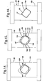
mid-section 69, the redistribution of material is important. As shown in Figure 13, around tube 69A is supported on a 45 millimeter x 51millimeter mandrel 96, having roundedcorners 97 that match the 56 millimeter inside diameter oftube 69A. A die 98 having anupper die section 99 and alower die section 100 includes anupper die cavity 110 and alower die cavity 101 that together define an elongated opening with across section 45 millimeters x 55 millimeters having 6.35 millimeter rounded corners, when thedie sections parting line 102. Referring to Figures 14 and 15, it is apparent that the distance the material ofrounded tube 69A must be moved to produce the rectangular shape is different than the distance required to form a uniformly square-shaped tube. In forming a rectangular section, the contact points 103 and 104 for the material that must move the furthest distance make contact first, initially producing an oval shape from thetube 69A. Thelower die section 100 includeslegs corners tube 69A in thepart line 102. After initial contact between thedie sections tube 69A, the material of thetube 69A separates from the roundedcorners 97, initially at opposite ends of adjacent rounded corners and next to the short sides of the rectangular-shapedmandrel 96. - Referring to Figure 16, as the upper and lower die
sections tube 69 is formed, withvoids 109 opened between thetube 69 and therounded corners 97 of themandrel 96. Uniform thickness of thetube 69 is maintained across the flat sides by compression of the tube between the flat sides of the mandrel and the planar sides of the die cavities. The process accumulates any added thickness at the corners of thetube 69 adjacent thevoids 109 since the corners are formed last with material length being pushed to the corner due to clearance between the inside of the tube and the mandreladjacent voids 109. - Accordingly, the present invention provides a vehicle suspension damper with a polygonal reservoir tube that solves the problem of packaging a shock or a strut into a limited space environment. Additionally, strength and fluid storage improvements allow enhanced design freedom in applying dampers to new applications.
Claims (7)
- A suspension damper comprising:A piston (21) reciprocally carried in a circular cylindrical cylinder tube (16), the piston (21) being attached to a piston rod (25) extending out from the cylinder tube (16), wherein the circular cylindrical cylinder tube (16) is carried in a reservoir tube (12) that includes a mid-section (30) with a polygonal cross section and includes an open end (15) with a circular cross section, wherein the open end (15) is closed by a rod guide assembly (20) that engages the reservoir tube (12) and the cylinder tube (16) and wherein the reservoir tube (12) includes a closed end (14) opposite the open end (15) that is circular in configuration (16) characterised by a mounting bracket (29) fixed near the closed end (14) of the reservoir tube (12) around the polygonal cross section mid-section (30) of the reservoir tube (12) and a spring seat (38) fixed on the reservoir tube (12) around the polygonal cross section mid-section (30) of the reservoir tube (12).
- A suspension damper according to claim 1 wherein the reservoir tube (12) includes a polygonal-to-round transition (35), wherein the spring seat (38) is engaged adjacent the polygonal-to-round transition (35).
- A suspension damper according to claim 1 wherein the polygonal cross section is rectangular in shape.
- A suspension damper according to claim 1 wherein the polygonal cross section is trapezoidal in shape.
- A suspension damper according to claim 1 wherein the polygonal cross section is square in shape.
- A suspension damper according to claim 1 wherein the mounting bracket (29) includes a body (40) with a U-shaped opening (41) that receives the reservoir tube (12) and includes a plate that is clamped to the body (40) capturing the reservoir tube (12) in the mounting bracket (29).
- A suspension damper according to claim 6 wherein the reservoir tube includes a closed end opposite the open end and includes a polygonal-to-round transition (34) near the closed end (14) wherein the mounting bracket (29) is positioned adjacent the polygonal-to-round transition (34).
Applications Claiming Priority (2)
| Application Number | Priority Date | Filing Date | Title |
|---|---|---|---|
| US942424 | 1997-10-01 | ||
| US08/942,424 US5944154A (en) | 1997-10-01 | 1997-10-01 | Suspension damper with polygonal reservoir tube |
Publications (3)
| Publication Number | Publication Date |
|---|---|
| EP0907037A2 EP0907037A2 (en) | 1999-04-07 |
| EP0907037A3 EP0907037A3 (en) | 2001-11-21 |
| EP0907037B1 true EP0907037B1 (en) | 2005-08-10 |
Family
ID=25478048
Family Applications (1)
| Application Number | Title | Priority Date | Filing Date |
|---|---|---|---|
| EP98202917A Expired - Lifetime EP0907037B1 (en) | 1997-10-01 | 1998-09-01 | Suspension damper polygonal reservoir tube |
Country Status (3)
| Country | Link |
|---|---|
| US (1) | US5944154A (en) |
| EP (1) | EP0907037B1 (en) |
| DE (1) | DE69831118T2 (en) |
Families Citing this family (10)
| Publication number | Priority date | Publication date | Assignee | Title |
|---|---|---|---|---|
| JP2003343634A (en) * | 2002-05-24 | 2003-12-03 | Showa Corp | Dust cover receiving structure of shock absorber |
| US7963377B2 (en) * | 2005-04-06 | 2011-06-21 | GM Global Technology Operations LLC | Dual stage dampers for vehicles suspensions |
| DE102006012086A1 (en) * | 2006-03-14 | 2007-09-20 | Muhr Und Bender Kg | Suspension strut made of flexibly rolled sheet metal |
| US8960389B2 (en) * | 2009-09-18 | 2015-02-24 | Specialized Bicycle Components, Inc. | Bicycle shock absorber with slidable inertia mass |
| US8336683B2 (en) * | 2008-05-09 | 2012-12-25 | Specialized Bicycle Components, Inc. | Bicycle damper |
| US7936113B2 (en) | 2009-02-27 | 2011-05-03 | GM Global Technology Operations LLC | Harvesting energy from vehicular vibrations using piezoelectric devices |
| JP5998162B2 (en) * | 2014-02-06 | 2016-09-28 | Kyb株式会社 | shock absorber |
| JP5766836B1 (en) * | 2014-03-12 | 2015-08-19 | 住友理工株式会社 | Dust cover assembly for vehicle and method for manufacturing the same |
| DE102015209181A1 (en) * | 2015-05-20 | 2016-11-24 | Zf Friedrichshafen Ag | Cylinder tube for a vibration damper |
| US10850584B2 (en) | 2016-06-07 | 2020-12-01 | Beijingwest Industries Co., Ltd. | Damper housing and a method for manufacturing the damper housing |
Family Cites Families (13)
| Publication number | Priority date | Publication date | Assignee | Title |
|---|---|---|---|---|
| US2025199A (en) * | 1934-06-28 | 1935-12-24 | Gen Motors Corp | Shock absorber |
| GB1491251A (en) * | 1974-10-19 | 1977-11-09 | Armstrong Patents Co Ltd | Vehicle wheel suspension struts including telescopic hydraulic shock absorbers |
| NL7810750A (en) * | 1977-11-04 | 1979-05-08 | Girling Ltd | VEHICLE SUPPORT UNIT. |
| FR2437310A1 (en) * | 1978-09-28 | 1980-04-25 | Allinquant J G | FIXING DEVICE FOR TELESCOPIC SUSPENSION SHOCK ABSORBERS |
| GB2076933B (en) * | 1980-06-03 | 1984-08-22 | Lucas Industries Ltd | Hydropneumatic suspension struts for vehicles |
| IT8352875V0 (en) * | 1983-01-26 | 1983-01-26 | Riv Officine Di Villar Perosa | BEARING SUPPORT FOR A WHEEL OF A VEHICLE |
| GB2155579B (en) * | 1984-03-08 | 1987-07-15 | Ford Motor Co | Torque-transmitting joint |
| DE4232136A1 (en) * | 1992-09-25 | 1994-03-31 | Fichtel & Sachs Ag | Shock absorber esp. shock strut with inner pipe for axially movable piston rod of piston - has equalising chamber with wider parts, and components such as steering lever, spring plate and or wheel supports. |
| US5607035A (en) * | 1994-10-13 | 1997-03-04 | Delphi France Automotive Systems | Hydraulic damper |
| US5638927A (en) * | 1995-09-18 | 1997-06-17 | General Motors Corporation | Suspension damper |
| GB2305991B (en) * | 1995-10-09 | 1999-07-07 | Draftex Ind Ltd | Gas spring |
| FR2755067B1 (en) * | 1996-10-31 | 1999-01-15 | Peugeot | DEVICE FOR SUSPENDING A MOTOR VEHICLE WHEEL AND METHOD FOR MACHINING A RAW PART FORMING A WHEEL SUPPORT FOR SUCH A DEVICE |
| US5855137A (en) * | 1997-10-01 | 1999-01-05 | General Motors Corporation | Method of manufacturing a reservoir tube |
-
1997
- 1997-10-01 US US08/942,424 patent/US5944154A/en not_active Expired - Fee Related
-
1998
- 1998-09-01 EP EP98202917A patent/EP0907037B1/en not_active Expired - Lifetime
- 1998-09-01 DE DE69831118T patent/DE69831118T2/en not_active Expired - Lifetime
Also Published As
| Publication number | Publication date |
|---|---|
| EP0907037A2 (en) | 1999-04-07 |
| DE69831118T2 (en) | 2006-02-09 |
| EP0907037A3 (en) | 2001-11-21 |
| US5944154A (en) | 1999-08-31 |
| DE69831118D1 (en) | 2005-09-15 |
Similar Documents
| Publication | Publication Date | Title |
|---|---|---|
| US5855137A (en) | Method of manufacturing a reservoir tube | |
| US4911416A (en) | Side load compensating air suspension | |
| JP2005042920A (en) | Damper | |
| WO2020086420A1 (en) | Damper with two-piece shell | |
| US5944154A (en) | Suspension damper with polygonal reservoir tube | |
| US5984060A (en) | Monotube strut assembly | |
| CN112594320B (en) | Inertial volume and magnetorheological damping fusion type suspension vibration damping mechanism | |
| US6182806B1 (en) | Hydraulic shock absorber | |
| JP2972620B2 (en) | shock absorber | |
| US11009095B2 (en) | Damper with monolithic base | |
| US5244064A (en) | Shock absorber | |
| JPH04158946A (en) | Manufacture of reservor tube for hydraulic shock absorber | |
| JP2005155793A (en) | Hydraulic shock absorber | |
| EP0076339A1 (en) | Telescopic shock absorber | |
| CN223178045U (en) | Hydraulic buffering and limiting mechanism for vehicle shock absorber | |
| CN211423247U (en) | Automobile shock absorber ware that stability is high | |
| CN220726961U (en) | Lower limit buffer structure of bidirectional cylinder type shock absorber | |
| JPH09229126A (en) | Shock absorber | |
| EP0497625B1 (en) | Shock absorber | |
| JPS5841398Y2 (en) | Cartridge shock absorber | |
| JPS6030498Y2 (en) | Strut type shock absorber | |
| CN218718400U (en) | High leakproofness bumper shock absorber oil storage jar | |
| JPS5855379B2 (en) | Kuukibanesouchi | |
| JP3068266U (en) | Shock absorber | |
| CN109441990A (en) | A kind of bitubular column support type automobile absorber |
Legal Events
| Date | Code | Title | Description |
|---|---|---|---|
| PUAI | Public reference made under article 153(3) epc to a published international application that has entered the european phase |
Free format text: ORIGINAL CODE: 0009012 |
|
| AK | Designated contracting states |
Kind code of ref document: A2 Designated state(s): AT BE CH CY DE DK ES FI FR GB GR IE IT LI LU MC NL PT SE Kind code of ref document: A2 Designated state(s): DE ES FR GB |
|
| AX | Request for extension of the european patent |
Free format text: AL;LT;LV;MK;RO;SI |
|
| RAP1 | Party data changed (applicant data changed or rights of an application transferred) |
Owner name: DELPHI TECHNOLOGIES, INC. |
|
| PUAL | Search report despatched |
Free format text: ORIGINAL CODE: 0009013 |
|
| AK | Designated contracting states |
Kind code of ref document: A3 Designated state(s): AT BE CH CY DE DK ES FI FR GB GR IE IT LI LU MC NL PT SE |
|
| AX | Request for extension of the european patent |
Free format text: AL;LT;LV;MK;RO;SI |
|
| 17P | Request for examination filed |
Effective date: 20020521 |
|
| AKX | Designation fees paid |
Free format text: DE ES FR GB |
|
| 17Q | First examination report despatched |
Effective date: 20040726 |
|
| GRAP | Despatch of communication of intention to grant a patent |
Free format text: ORIGINAL CODE: EPIDOSNIGR1 |
|
| GRAS | Grant fee paid |
Free format text: ORIGINAL CODE: EPIDOSNIGR3 |
|
| GRAA | (expected) grant |
Free format text: ORIGINAL CODE: 0009210 |
|
| AK | Designated contracting states |
Kind code of ref document: B1 Designated state(s): DE ES FR GB |
|
| REG | Reference to a national code |
Ref country code: GB Ref legal event code: FG4D |
|
| REF | Corresponds to: |
Ref document number: 69831118 Country of ref document: DE Date of ref document: 20050915 Kind code of ref document: P |
|
| PG25 | Lapsed in a contracting state [announced via postgrant information from national office to epo] |
Ref country code: GB Free format text: LAPSE BECAUSE OF NON-PAYMENT OF DUE FEES Effective date: 20051110 |
|
| PG25 | Lapsed in a contracting state [announced via postgrant information from national office to epo] |
Ref country code: ES Free format text: LAPSE BECAUSE OF FAILURE TO SUBMIT A TRANSLATION OF THE DESCRIPTION OR TO PAY THE FEE WITHIN THE PRESCRIBED TIME-LIMIT Effective date: 20051121 |
|
| PLBE | No opposition filed within time limit |
Free format text: ORIGINAL CODE: 0009261 |
|
| STAA | Information on the status of an ep patent application or granted ep patent |
Free format text: STATUS: NO OPPOSITION FILED WITHIN TIME LIMIT |
|
| 26N | No opposition filed |
Effective date: 20060511 |
|
| GBPC | Gb: european patent ceased through non-payment of renewal fee |
Effective date: 20051110 |
|
| PG25 | Lapsed in a contracting state [announced via postgrant information from national office to epo] |
Ref country code: FR Free format text: LAPSE BECAUSE OF FAILURE TO SUBMIT A TRANSLATION OF THE DESCRIPTION OR TO PAY THE FEE WITHIN THE PRESCRIBED TIME-LIMIT Effective date: 20060811 |
|
| EN | Fr: translation not filed | ||
| PG25 | Lapsed in a contracting state [announced via postgrant information from national office to epo] |
Ref country code: FR Free format text: LAPSE BECAUSE OF FAILURE TO SUBMIT A TRANSLATION OF THE DESCRIPTION OR TO PAY THE FEE WITHIN THE PRESCRIBED TIME-LIMIT Effective date: 20050930 |
|
| PG25 | Lapsed in a contracting state [announced via postgrant information from national office to epo] |
Ref country code: FR Free format text: LAPSE BECAUSE OF FAILURE TO SUBMIT A TRANSLATION OF THE DESCRIPTION OR TO PAY THE FEE WITHIN THE PRESCRIBED TIME-LIMIT Effective date: 20050810 |
|
| PGFP | Annual fee paid to national office [announced via postgrant information from national office to epo] |
Ref country code: DE Payment date: 20170830 Year of fee payment: 20 |
|
| REG | Reference to a national code |
Ref country code: DE Ref legal event code: R071 Ref document number: 69831118 Country of ref document: DE |
|
| REG | Reference to a national code |
Ref country code: DE Ref legal event code: R082 Ref document number: 69831118 Country of ref document: DE Ref country code: DE Ref legal event code: R081 Ref document number: 69831118 Country of ref document: DE Owner name: BWI COMPANY LIMITED S.A., LU Free format text: FORMER OWNER: DELPHI TECHNOLOGIES, INC., TROY, MICH., US |