EP0906536B1 - Abrasion protection - Google Patents
Abrasion protection Download PDFInfo
- Publication number
- EP0906536B1 EP0906536B1 EP97925171A EP97925171A EP0906536B1 EP 0906536 B1 EP0906536 B1 EP 0906536B1 EP 97925171 A EP97925171 A EP 97925171A EP 97925171 A EP97925171 A EP 97925171A EP 0906536 B1 EP0906536 B1 EP 0906536B1
- Authority
- EP
- European Patent Office
- Prior art keywords
- sheath
- filaments
- fabric
- heat
- length
- Prior art date
- Legal status (The legal status is an assumption and is not a legal conclusion. Google has not performed a legal analysis and makes no representation as to the accuracy of the status listed.)
- Expired - Lifetime
Links
Images

Classifications
-
- F—MECHANICAL ENGINEERING; LIGHTING; HEATING; WEAPONS; BLASTING
- F16—ENGINEERING ELEMENTS AND UNITS; GENERAL MEASURES FOR PRODUCING AND MAINTAINING EFFECTIVE FUNCTIONING OF MACHINES OR INSTALLATIONS; THERMAL INSULATION IN GENERAL
- F16L—PIPES; JOINTS OR FITTINGS FOR PIPES; SUPPORTS FOR PIPES, CABLES OR PROTECTIVE TUBING; MEANS FOR THERMAL INSULATION IN GENERAL
- F16L57/00—Protection of pipes or objects of similar shape against external or internal damage or wear
- F16L57/06—Protection of pipes or objects of similar shape against external or internal damage or wear against wear
-
- B—PERFORMING OPERATIONS; TRANSPORTING
- B29—WORKING OF PLASTICS; WORKING OF SUBSTANCES IN A PLASTIC STATE IN GENERAL
- B29C—SHAPING OR JOINING OF PLASTICS; SHAPING OF MATERIAL IN A PLASTIC STATE, NOT OTHERWISE PROVIDED FOR; AFTER-TREATMENT OF THE SHAPED PRODUCTS, e.g. REPAIRING
- B29C61/00—Shaping by liberation of internal stresses; Making preforms having internal stresses; Apparatus therefor
- B29C61/06—Making preforms having internal stresses, e.g. plastic memory
- B29C61/0608—Making preforms having internal stresses, e.g. plastic memory characterised by the configuration or structure of the preforms
- B29C61/0658—Making preforms having internal stresses, e.g. plastic memory characterised by the configuration or structure of the preforms consisting of fibrous plastics material, e.g. woven
-
- D—TEXTILES; PAPER
- D03—WEAVING
- D03D—WOVEN FABRICS; METHODS OF WEAVING; LOOMS
- D03D1/00—Woven fabrics designed to make specified articles
- D03D1/0035—Protective fabrics
- D03D1/0043—Protective fabrics for elongated members, i.e. sleeves
-
- D—TEXTILES; PAPER
- D03—WEAVING
- D03D—WOVEN FABRICS; METHODS OF WEAVING; LOOMS
- D03D3/00—Woven fabrics characterised by their shape
- D03D3/02—Tubular fabrics
-
- F—MECHANICAL ENGINEERING; LIGHTING; HEATING; WEAPONS; BLASTING
- F16—ENGINEERING ELEMENTS AND UNITS; GENERAL MEASURES FOR PRODUCING AND MAINTAINING EFFECTIVE FUNCTIONING OF MACHINES OR INSTALLATIONS; THERMAL INSULATION IN GENERAL
- F16L—PIPES; JOINTS OR FITTINGS FOR PIPES; SUPPORTS FOR PIPES, CABLES OR PROTECTIVE TUBING; MEANS FOR THERMAL INSULATION IN GENERAL
- F16L47/00—Connecting arrangements or other fittings specially adapted to be made of plastics or to be used with pipes made of plastics
- F16L47/20—Connecting arrangements or other fittings specially adapted to be made of plastics or to be used with pipes made of plastics based principally on specific properties of plastics
- F16L47/22—Connecting arrangements or other fittings specially adapted to be made of plastics or to be used with pipes made of plastics based principally on specific properties of plastics using shrink-down material
-
- G—PHYSICS
- G02—OPTICS
- G02B—OPTICAL ELEMENTS, SYSTEMS OR APPARATUS
- G02B6/00—Light guides; Structural details of arrangements comprising light guides and other optical elements, e.g. couplings
- G02B6/44—Mechanical structures for providing tensile strength and external protection for fibres, e.g. optical transmission cables
- G02B6/4401—Optical cables
- G02B6/4429—Means specially adapted for strengthening or protecting the cables
- G02B6/443—Protective covering
-
- G—PHYSICS
- G02—OPTICS
- G02B—OPTICAL ELEMENTS, SYSTEMS OR APPARATUS
- G02B6/00—Light guides; Structural details of arrangements comprising light guides and other optical elements, e.g. couplings
- G02B6/44—Mechanical structures for providing tensile strength and external protection for fibres, e.g. optical transmission cables
- G02B6/4439—Auxiliary devices
- G02B6/4459—Ducts; Conduits; Hollow tubes for air blown fibres
-
- G—PHYSICS
- G02—OPTICS
- G02B—OPTICAL ELEMENTS, SYSTEMS OR APPARATUS
- G02B6/00—Light guides; Structural details of arrangements comprising light guides and other optical elements, e.g. couplings
- G02B6/44—Mechanical structures for providing tensile strength and external protection for fibres, e.g. optical transmission cables
- G02B6/4439—Auxiliary devices
- G02B6/4471—Terminating devices ; Cable clamps
- G02B6/4476—Terminating devices ; Cable clamps with heat-shrinkable elements
-
- Y—GENERAL TAGGING OF NEW TECHNOLOGICAL DEVELOPMENTS; GENERAL TAGGING OF CROSS-SECTIONAL TECHNOLOGIES SPANNING OVER SEVERAL SECTIONS OF THE IPC; TECHNICAL SUBJECTS COVERED BY FORMER USPC CROSS-REFERENCE ART COLLECTIONS [XRACs] AND DIGESTS
- Y10—TECHNICAL SUBJECTS COVERED BY FORMER USPC
- Y10T—TECHNICAL SUBJECTS COVERED BY FORMER US CLASSIFICATION
- Y10T428/00—Stock material or miscellaneous articles
- Y10T428/13—Hollow or container type article [e.g., tube, vase, etc.]
- Y10T428/1352—Polymer or resin containing [i.e., natural or synthetic]
- Y10T428/1362—Textile, fabric, cloth, or pile containing [e.g., web, net, woven, knitted, mesh, nonwoven, matted, etc.]
Definitions
- the present invention relates to the use of a fabric sheath, or other article, on a conduit, for example a pipe or flexible hose, to provide abrasion resistance or other forms of protection, for example impact protection or cut-through protection, thereto, and relates to fabric sheaths suitable for such use.
- a fabric sheath or other article
- a conduit for example a pipe or flexible hose
- abrasion resistance or other forms of protection for example impact protection or cut-through protection
- One aspect of the invention relates to circumferentially-heat-shrinkable sheaths of woven fabric for use in providing abrasion protection to conduits.
- the conduits may be fluid or electrical conduits, or other elongate guiding forms, such as electrical wiring bundles or harnesses, or electrical or optical cables.
- hoses etc. Mechanical protection of hoses etc. is often found to be necessary because it is difficult to provide all of the desired properties in a single material.
- a hose must in general be impermeable to fluids, flexible and heat-resistant.
- the preferred materials for providing those properties often have poor abrasion and cut-through resistance.
- US 5413149 (Bentley Harris) discloses a flexible, kink-resistant shaped fabric product for protecting and/or covering cables, conduits and wiring etc.
- the shaped fabric has a wall portion comprising a filament resiliently set in a spiral configuration with respect to the longitudinal axis of the shaped product.
- the wall portion may also comprise a filament in the form of circumferential hoops substantially conforming in shape and size to the cross-sectional configuration of the shaped product.
- thermoplastic filaments are heated to a temperature above their glass transition point and are then cooled to cause recrystalization or "set" of the filaments.
- the resulting product then has the desired spiral resilient bias. This is stated to be an "elastic memory”.
- one aspect of the present invention accordingly provides the use of a circumferentially heat-shrinkable fabric sheath to provide abrasion resistance to a non-linear shaped conduit, for example a pipe or flexible hose, wherein the sheath when circumferentially heat shrunk also undergoes some longitudinal shrinkage.
- a weave in particular a plain weave, although other weaves such as a 2/2 twill would be suitable.
- a weave I prefer that one set of fibres runs substantially parallel to the length of the sheath, and another set of fibres runs substantially circumferentially of the sheath. If the sheath is to be made continuously in line, it will be desirable (at least when using a narrow fabric loom) for the warp fibres to become the longitudinal fibres of the sheath, and the weft fibres to become the circumferential fibres of the sheath.
- circumferential fibres those that are ideal for the provision of heat-shrink properties
- longitudinal fibres those which are ideal for provision of abrasion-resistance, for example toughness, resistance to notch propagation, low coefficient of friction, impact resistance, and high temperature performance.
- Such fibres preferably predominate on an external surface of the sheath.
- high density polyethylene (HDPE) as the circumferential fibres and to use a polyester, such as polyethylene terephthalate, or a nylon in the warp direction.
- suitable circumferential fibres include polyolefins such as low density polyethylene, medium density polyethylene, polypropylene/polyethylene copolymers and fluoropolymers such as polyvinylidene difluoride (PVDF) and ethylene chlorotrifluoroethylene (E-CTFE).
- suitable longitudinal fibres include polyacryonitrile and copolymers thereof, polyphenylene sulphide, cellulose acetate, aromatic polyamides, eg Kevlar, natural fibres and fluoro polymers.
- the longitudinal abrasion-resistant fibres are preferably able to flatten-out and/or to move under the influence of an adjacent surface. This ability to flatten-out or to move results in that surface causing less damage to the fibres.
- the longitudinal fibres comprise multi-filament bundles since the filaments within each bundle will be able to move slightly with respect to one another. At present I prefer to use a co-mingled yarn.
- a further advantage of multifilament bundles is that cut-through of any filament results in less overall damage to the product.
- the circumferential, heat-shrinkable, fibres may comprise simple monofilaments.
- Various preferred characteristics of the product can be achieved by suitable selection of the weave density, weave design, and weaving process.
- a high-density weave, or weave using fibres of high tex value be used to achieve a high optical coverage.
- Optical coverage is a well-known term that simply relates the percentage of a plan view of a fabric that is taken up by the fibres themselves, rather than by the interstices between then.
- the optical coverage, at least after shrinkage is preferably at least 75%, more preferably at least 95%, most preferably substantially 100%.
- a second preferred characteristic of a fabric is that it be ribbed, preferably warp ribbed. This means that the fabric will have a surface relief comprising a series of parallel ribs. If the hose is to be protected from abrasion caused by an adjacent surface moving longitudinally with respect to the hose, it will generally be preferable for ribs to be provided that run circumferentially of the hose. Ribbed fabrics are well understood in the weaving art, and warp ribbed fabrics may be constructed by inserting several weft picks in succession into the same shed of an ordinary plain weave. A warp ribbed fabric will in general be woven with a larger number of ends than picks. The weft yarn generally has less twist than the warp yarn and is of heavier linear density, and if it is a single monofilament it will have zero twist.
- Crimp is another characteristic of the fabric that may be considered.
- the crimp is predominantly in the longitudinal direction of the sheath.
- the circumferential fibres are preferably monofilaments, and the longitudinal fibres preferably comprise multifilament bundles. More particularly, the longitudinal fibres comprise five to ten fold (particularly about seven fold) bundles, each of the fibres within each bundle again comprising a bundle of very fine filaments.
- Each of the folds is preferably 10-20 tex, (preferably about 17 tex (tex being the ISO standard for linear density of textile strands and is the weight in grams of 1000 m) and each of those filaments preferably comprises 30-40 very fine filaments.
- the circumferential fibres preferably have a tex value of 5-200, more preferably 20-100, especially 30-60.
- the sheath of the invention is easy to secure in place around the hose to be protected.
- the sheath may be produced in long lengths, cut to length, slid over the hose and then heat-shrunk around the hose to locate it in position.
- the desired shrinkage ratio for this purpose is from 1.2:1 to 5:1.
- the lower value will be suitable where the hose to be protected is straight and where installation at low tolerances is simple.
- Shrink ratios greater than, say, 5:1 might be difficult to achieve in practice and might result in instability or uneven shrinkage during installation. In general I prefer a shrink ratio between 1.5:1 and 4:1.
- the longitudinal shrinkage tends to avoid wrinkling at the bends in the hose.
- I can include heat-shrinkable fibres in the longitudinal direction.
- a longitudinal shrinkage ratio of from 1-20%, more preferably 2-10%, will generally be suitable.
- Shrinkage when expressed as a ratio means a dimension before shrinkage compared to the dimension after shrinkage. When expressed as a percentage it means the change in a dimension, based on the dimension before change.
- the sheath is produced in long lengths it will usually require cutting before installation. This can conveniently be done by a hot blade such as a hot knife, which not only cuts the fibres but welds them together at the new end of the sheath to prevent fraying. It is therefore desirable that the fibres be thermoplastic, and therefore not excessively cross-linked during their manufacture.
- Some degree of cross-linking of at least some of the fibres of the sheath may be desirable to render the sheath heat-shrinkable.
- the circumferential fibres which by virtue of their heat-shrinkability, drive shrinkage of the overall product, are preferably cross-linked and stretched before weaving of the fabric. They may be cross-linked and then stretched at an elevated temperature and then cooled, or the heating, stretching and cooling may precede the cross-linking.
- it will be desirable to weave the fabric from heat-shrinkable fibres although in some circumstances it may be preferred to produce the fabric from heat-stable fibres, and then stretch the fabric.
- the longitudinal fibres can readily be welded at their ends by the hot-knife cutting.
- the overall fabric either by cross-linking separately all of the fibres from which it is to be made, or by cross-linking the woven fabric) in order to ensure that all of the fibres retain their integrity at high temperatures.
- the sheath may be produced in the form of a tube, or other structure closed in cross-section or it may be woven as a sheet and later formed into a tube either before or during installation.
- a product formed into a tube during installation known as a "wraparound sleeve" may be provided with a so-called closure mechanism to hold it in the wrapped around configuration around the hose.
- the sheath may be provided with some form of visual marking either for identifying it or as a means of determining when it has been subjected to abrasion.
- a logo of distinguishing colour may be woven into the sheath using for example a Jaquard mechanism on a narrow fabric or other weaving machine.
- Such a logo may serve to identify the product as that of a particular company, it may be provided for aesthetic reasons, or it may be provided to indicate the nature of the fluid that the underlying hose is carrying. For example, hoses containing dangerous fluids or hoses that will become hot during use may be provided with a marking in red etc. by way of a warning.
- Indication of abrasion may be provided as follows. Abrasion-susceptible fibres may be woven into the sheath such that they predominate on the external surface of the sheath that is likely to become abraded. If these abrasion-susceptible fibres are of a distinguishing colour with respect to the remainder of the sheath then the appearance of the sheath will change as it becomes abraded. Full protection of the underlying hose may continue to be provided long after the sacrificial fibres have been destroyed. Thus, periodic inspection will reveal that abrasion has occurred and will alert someone to take suitable action, either to prevent a further abrasion or to replace the now partly worn sheath.
- the materials may be chosen to ensure high temperature performance, oil resistance, acid resistance, and resistance to a variety of other chemicals.
- a heat-shrinkable fabric sheath was provided as follows.
- a narrow fabric loom was used to produce a heat-shrinkable fabric sheath of 3cm diameter in a plain weave having lengthwise warp and circumferential weft.
- the weft was a cross-linked high density polyethylene monofilament of 43.4 tex and the warp fibres consisted of seven fold polyethylene terephthalate multifilaments, each of the seven filaments itself consisting of thirty four very fine filaments.
- Each of the seven multifilaments had a tex value of 16.7.
- the warp density was 38 ends per cm and the weft density was 13 picks per cm.
- a section of sheath of length 25 cm was cut by means of a hot knife causing the polyethylene terephthalate warp fibres to weld together to prevent fraying.
- the sheath was slid over a rubber hose of 1cm diameter and was then shrunk in place.
- the hose was pre-shaped and the sheath shrunk to follow the contours of the shaped hose without wrinkling.
- An abrasion test was carried out using a modified form of scrape test BS5173 using both a flat blade and a pointed blade.
- the flat blade was weighted with 500g and the pointed blade weighted with 200g.
- the tests were carried out at 100°C. In each case no damage whatsoever had occurred after 4000 cycles.
- the fabric of these sheaths comprises filaments extending substantially circumferentially around the sheath (hereinafter “hoop filaments”), at least some of which hoop filaments are heat-shrinkable, and filaments extending substantially along the sheath (hereinafter “length filaments”), and it is mentioned that some degree of longitudinal shrinkage, to avoid the problem of wrinkling of the sheath at bends in the conduits, may be provided by incorporating heat-shrinkable fibres extending in the longitudinal direction.
- hoop filaments filaments extending substantially circumferentially around the sheath
- length filaments filaments extending substantially along the sheath
- Another aspect of the present invention ingeniously addresses this wrinkling problem by providing a circumferentially-heat-shrinkable sheath of woven fabric, capable of use on a conduit, for example to provide abrasion resistance as described and claimed in co-pending British Patent Application No.
- the sheath provides a substantially unobscured outer fabric surface and comprises hoop filaments extending substantially circumferentially around the sheath, at least some of which hoop filaments are heat-shrinkable, and length filaments extending substantially along the sheath, which length filaments are preferably dimensionally substantially heat-stable, and wherein the length filaments are selected either (A) to be sufficiently flexible, at least at temperatures to which they are subjected during heat-shrinking of the sheath in use, for the heat shrinkage of the hoop filaments to crimp the length filaments to an extent (a) producing at least 1%, preferably at least 2%, more preferably at least 5%, longitudinal shrinkage of the sheath in addition to any longitudinal heat shrinkage thereof and/or (b) causing portions of the length filaments to project outwardly from the shrunken fabric sheath to a maximum distance greater than the maximum projection distance of the thus-shrunken hoop filaments
- the longitudinal shrinkage of the sheaths due to crimping of the length filaments by the heat-shrinking hoop filaments (hereinafter "crimp shrinkage” for brevity) and/or the greater projection of the length filaments after heat-shrinkage of the sheath (hereinafetr "crimp hiding" of the hoop filaments) may be achieved or enhanced by holding the length filaments under tension during weaving of the fabric, so as to resist (to a desired extent) crimping by the relatively low weaving tension of the hoop filaments.
- the hoop filament tension is maintained as low as practicable to avoid undesired constriction of the tubular sheath as it is progressively formed.
- the heat-shrinking of the hoop filaments may nevertheless tend to produce useful longitudinal crimp shrinkage and/or crimp hiding owing to the accompanying increase in hoop filament thickness which increases the depth of the initial crimp in the length filaments.
- Relatively stiff length filaments may be used to limit the crimp shrinkage may be useful to enable selection of a uniquely controllable degree of crimp shrinkage, using the stiffer length filaments alone or together with more flexible length filaments. Controlled crimp shrinkage may be especially useful in applications where the final length of the sheath is required to match a specific length of conduit on which it is used. Suitable stiffer length filaments may be selected by simple trial and error, for example from plastics monofilaments or possibly glass filaments.
- the fabric sheath it is preferred to construct the fabric sheath so that it will have longitudinal crimp shrinkage within the range from 10 to 20 % on unrestricted circumferential heat-shrinkage (that is shrinkage to its fullest extent without any conduit or other substrate inside the sheath).
- the crimp shrinkage will normally be less than the unrestricted maximum, due to the presence of such a conduit or substrate, which will halt the circumferential shrinkage, and thus also the crimp shrinkage, at an intermediate stage as the sheath tightens around it.
- there will be negligible longitudinal heat-shrinkage for example less than 5%, preferably less than 2%, more preferably not more than 1%.
- the parameters responsible for producing the crimp shrinkage are dominated by the flexibility of the length filaments, which will preferably be evident at ambient temperatures, but may be provided by length filaments which are relatively stiff and inflexible at ambient temperatures, but become adequately more flexible at temperatures to which they are subjected during the heat-shrinking of the sheath in use.
- Other fabric parameters such as weave design, number of weft insertions, or number of warp ends, tend to have relatively little effect on the crimp shrinkage of the length filaments and/or crimp hiding of the hoop filaments.
- a weave design in which the length filaments pass over three hoop filaments may produce less initial crimp in the length filaments than would occur in a plain "1-in-1" weave. Fewer weft insertions per unit length and/or fewer warp ends per unit length may tend to increase the longitudinal crimp shrinkage, while too many of either may produce a fabric in which the desired heat-shrinkage is hindered by undesirably tight weaving. Thus, a balance may be struck to some extent by simple trial and error between the looseness or tightness of the weave and the degree of additional crimp shrinkage desired. However, these factors are minor compared with the effect of the length filament flexibility on the degree of crimp shrinkage and/or crimp hiding achieved in practice.
- the tension and flexibility of the length filaments will preferably be sufficient to cause them to project outwardly from the fabric to a lesser extent than the hoop filaments, which hoop filaments will therefore tend to undulate over and under the relatively straighter length filaments.
- the length filaments will preferably be woven to project outwardly from the fabric to a maximum distance less than 85%, preferably less than 70%, more preferably less than 55%, of the maximum projection of the hoop filaments.
- the heat-shrinkage forces of the hoop filaments will preferably be sufficient to crimp the length filaments to an extent which causes them to project outwardly from the shrunken fabric sheath to a maximum distance greater than, preferably at least 25% greater than, more preferably at least 50% greater than, especially at least 75% greater than, the maximum projection distance of the shrunken hoop filaments. It is advantageous for the flexibility of the length filaments and the shrinkage forces of the hoop filaments to be sufficient to cause the crimped length filaments subsatntially to conceal the shrunken hoop filaments after the heat-shrinking step.
- the projection distances may be understood as being measured to the outermost surface of the hoop or length filaments, whichever is on top as they pass over and under each other.
- the hoop and length filaments pass alternately over and under each other, so that the projection distance of a hoop filament where it passes over one of the length filaments may be compared with the projection distance of that same length filament where it passes over the immediately adjacent hoop filament.
- the projection distances may be measured from any convenient fixed point, for example a plane lying parallel with the fabric and contacting the innermost points of the inner fabric surface, or a similar plane passing through the mid-point of the fabric thickness.
- circumferentially-heat-shrinkable sheaths does not necessarily limit the invention to tubular sheaths of substantially circular cross-section.
- Sheaths of square, triangular, hexagonal, or any other desired tubular cross-section whether woven as tubes or formed by wrapping around and fastening a fabric originally woven as a sheet, may be included, provided that they are heat-shrinkable in the direction of the perimeter so as to narrow the tube, thus enabling them to contract around and grip the conduits to which they provide abrasion resistance in use.
- the sheath provides a substantially unobscured outer fabric surface
- the sheath may include sealed heat-shrinkable fabrics whose external surface is covered with a layer of polymeric material of at least 0.03 mm thickness, as described for example in EP-A-0117026 (RK176), but may include fabrics with coatings from which at least parts of the filaments project to provide an abrasion-resisting contact function in use.
- the hoop filaments in this aspect of the present invention extend substantially circumferentially around the sheath, as distinct from the helical filaments of a braid, which extend very noticeably along the sheath as well as around it.
- the length filaments of the fabric according to the present invention extends substantially along the sheath, preferably substantially parallel with the sheath tubular axis, although a certain amount of helical curvature of these length filaments may be tolerable in practice and is to be understood as included within the expression "substantially along the sheath”. It is generally preferred, though not essential, that the hoop filaments are provided by the weft of the fabric and the length filaments are provided by the warp of the fabric.
- the invention also includes a method of making the sheaths hereinbefore described by weaving with the length (preferably warp) filaments held under sufficiently high tension and the hoop (preferably weft) filaments under sufficiently low tension to produce the aforesaid crimp shrinkage effect.
- the length filaments are preferably multi-filament yarns, especially substantially-untwisted tows, for enhanced abrasion resistance, as mentioned in the aforesaid co-pending application.
- Multi-filament yarns tend to spread out to enhance their surface coverage, while their degree of surface projection from the sheath may be only a few multi-filaments deep, thus advantageously reducing the degree of strain imposed on the filament material at outside bend radii.
- the spreading and flexibility of multi-filaments yarns may also produce advantageous softness and noise-deadening impact insulation effects to reduce rattling in vehicles and other end uses.
- Mono-filaments or tape-like length filaments could nevertheless be used, provided they are flexible enough to provide a useful degree of crimp shrinkage and/or crimp hiding.
- the exact degree of flexibility is not readily quantifiable, but will generally be greater than that of relatively brittle materials such as glass fibre and can readily be tested by trial and error in practice. Lower flexibility may to some extent be better tolerated as the diameter of the filaments decreases.
- the fabric of the sheath may usefully be woven so as to provide the sheath before shrinking with a degree of longitudinal stretch, preferably less than 10%, more preferably within the range from 0.5% to 5%, especially 1% to 3%.
- a degree of longitudinal stretch may enable the sheath better to accomodate stretching around the outside of bends in the conduit onto which it is fitted in use, thus facilitating initial positioning on the conduit and co-operating with the wrinkle-removing effect of the crimp shrinkage on the inside of the bends to enhance the appearance of the final shrunken sheath thereon.
- Such longitudinal stretch may be influenced by the length filament structure, softer multi-filament yarns for example tending to give greater stretch, and by the weave design, the aforementioned looser "3-in-1" weaves for example tending to allow greater stretching than tighter plain weaves.
- FIG. 1 the hose is designated 1, the sheath 2, and the cut and sealed ends of the sheath 3. Circumferential ribs 4 can be seen along the length of the sheath.
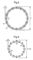
- Fig. 2 shows a sheath having notionally straight length filaments 10 formed by the warp of a plain weave under suitably high weaving tension, and shows two of the heat-shrinkable hoop filaments 12, 14 adjacent to each other formed by the weft, giving the substantially circular sheath an outer diameter D.
- ⁇ P the distance between the hoop filaments 12, 14 project further outwards than the length filaments 10 by a distance ⁇ P, which is approximately equal to the thickness of the hoop filaments in this idealised construction having straight length filaments.
- Figure 3 shows the sheath of Fig. 2 after the hoop filaments 12, 14 have been heat shrunk, thus reducing the sheath diameter by an amount ⁇ D.
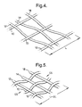
- Figures 4 and 5 illustrate in idealised perspective the lengthwise crimp shrinkage of the length filaments 10 resulting from the circumferential heat shrinkage of the hoop filaments 12, 14, 18.
- the straightening of the undulating hoop filaments 12, 14, 18 of Fig. 4 induces crimping of the originally straight length filaments 10 as shown in Fig. 5, thus reducing the length L of the sheath fabric by an amount ⁇ L.
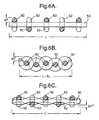
- Figures 6A to 6C illustrate the crimp shrinkage in another view, looking sideways at a length filament 50 of length L, behind which can be seen (in Figs. 6B and 6C) another length filament 52.
- the hoop filaments 60 can be seen above and below the notionally straight length filament 50 in Fig. 6A, with further portions 62 of the hoop filaments visible where they pass over the concealed length filament 52.
- the hoop filaments project outwards further than the length filaments by a distance ⁇ P, roughly equal to the hoop filament thickness as before.
- the length filaments 50, 52 are crimped, reducing the sheath length by an amount ⁇ L as shown in Fig.
- the length filaments 50, 52 now project outwardly by a greater distance ⁇ P' than the hoop filaments 60.
- the length filaments 50, 52 are unlikely to be woven perfectly straight in the unshrunken fabric sheath, and may tend to undulate somewhat over and under the hoop filaments 60 (and their nether portions 62), as shown in Fig. 6C.
- the incremental projection ⁇ P" of the unshrunk hoop filaments will be less than that shown as ⁇ P in Fig. 6A.
- the unshrunken sheath length L' will be less than the notional length L of Fig. 6A, so that the lengthwise crimp shrinkage may be proportionally smaller when the hoop filaments are heat shrunk.
Abstract
Description
Claims (26)
- The use of a circumferentially heat-shrinkable fabric sheath to provide abrasion resistance to a non-linear shaped conduit, wherein the sheath when circumferentially heat shrunk also undergoes some longitudinal shrinkage
- The use according to claim 1, in which the conduit comprises a flexible hose.
- The use according to claim 1 or 2, in which the fabric comprises a weave having flexible fibres running substantially parallel to the length of the sheath, and fibres running substantially circumferentially of the sheath.
- The use according to claim 1, 2 or 3, in which the fabric after shrinkage has an optical coverage of at least 75 %.
- The use according to any preceding claim, in which the sheath has a circumferential shrinkage ratio of from 1.5:1 to 4:1.
- The use according to any preceding claim, in which the sheath has a longitudinal shrinkage ratio of from 1 to 20%.
- The use according to any preceding claim, in which the fabric has a crimp that is predominantly in the longitudinal direction of the sheath.
- The use according to any preceding claim, in which the fabric is ribbed, having its ribs running substantially circumferentially of the sheath.
- The use according to any preceding claim, in which the fabric is a weave having its warp in the longitudinal direction of the sheath.
- The use according to any preceding claim, in which the longitudinal fibres comprise multi-filament bundles, preferably co-mingled yarn.
- The use according to any preceding claim, in which the circumferential fibres comprise monofilaments.
- , The use according to any preceding claim, in which the fabric comprises a weave having 25-60 warp ends per cm.
- The use according to any preceding claim, in which the fabric comprises a weave having from 3-20 weft picks per cm.
- The use according to any preceding claim, in which fibres which predominate on an external surface of the sheath comprise a polyester or a nylon.
- The use according to any preceding claim, in which the sheath is heat-shrinkable by virtue of heat-shrinkable polyethylene fibres thereof.
- The use according to any preceding claim, in which the sheath is cut-to-length by means of a hot blade.
- A circumferentially-heat-shrinkable sheath of woven fabric, capable of use on a non-linear shaped conduit, for example to provide impact cushioning and/or abrasion resistance, wherein the sheath provides a substantially unobscured outer fabric surface and comprises
hoop filaments extending substantially circumferentially around the sheath, at least some of which hoop filaments are heat-shrinkable, and
length filaments extending substantially along the sheath,
and wherein the length filaments are selected to be sufficiently flexible, at least at temperatures to which they are subjected during heat-shrinking of the sheath in use, for the heat shrinkage of the hoop filaments to crimp the length filaments to an extent(a) producing at least 1%, preferably at least 2%, more preferably at least 5%, longitudinal shrinkage of the sheath in addition to any longitudinal heat shrinkage thereof and/or(b) causing portions of the length filaments either(i) to project outwardly from the shrunken fabric sheath to a maximum distance in excess of the maximum projection distance of the thus-shrunken hoop filaments, or(ii) to increase such excess projection distance if already existing before the heat shrinkage. - A sheath according to claim 17, wherein the length filaments are dimensionally substantially heat-stable at temperatures encountered during the heat-shrinkage of the sheath.
- A sheath according to claim 17 or 18, wherein the hoop filaments are provided by the weft of the fabric and the length filaments are provided by the warp of the fabric.
- A sheath according to any of claims 17 to 19, wherein the sheath has been rendered more susceptible to the said longitudinal shrinkage (crimp shrinkage) by holding the length filaments under higher-than-normal tension so as to resist crimping of the length filaments during weaving of the fabric, the hoop filaments being held at relatively lower weaving tension during weaving.
- A sheath according to claim 20, wherein the tension of the length filaments is sufficient to cause them to project outwardly from the fabric to a lesser extent than the hoop filaments.
- A sheath according to claim 21, wherein the length filaments are woven to project outwardly from the fabric to a maximum distance less than 85%, preferably less than 70%, more preferably less than 55%, of the maximum projection of the hoop filaments.
- A sheath according to any of claims 17 to 22, wherein the heat-shrinkage forces of the hoop filaments and the flexibility of the length filaments are sufficient to crimp the length filaments to an extent which causes them to project outwardly from the fully shrunken fabric sheath to a maximum distance at least 25% greater than, preferably at least 50% greater than, especially at least 75% greater than, the maximum projection distance of the fully heat-shrunken hoop filaments.
- A sheath according to any of claims 17 to 23, wherein portions of the hoop filaments are clearly visible from the exterior of the sheath before heat shrinking and the length filaments substantially conceal the hoop filaments from exterior view in the fully heat-shrunken sheath.
- A sheath according to any of claims 17 to 24, which before shrinking has a degree of longitudinal stretch less than 10%, preferably within the range from 0.5% to 5%.
- Use of a sheath according to any of claims 17 to 25 according to any of claims 1 to 16.
Priority Applications (1)
| Application Number | Priority Date | Filing Date | Title |
|---|---|---|---|
| DE69717442.5T DE69717442T3 (en) | 1996-06-18 | 1997-06-06 | WEAR PROTECTION |
Applications Claiming Priority (5)
| Application Number | Priority Date | Filing Date | Title |
|---|---|---|---|
| GB9612667 | 1996-06-18 | ||
| GBGB9612667.7A GB9612667D0 (en) | 1996-06-18 | 1996-06-18 | Abrasion protection |
| GB9710352 | 1997-05-21 | ||
| GBGB9710352.7A GB9710352D0 (en) | 1997-05-21 | 1997-05-21 | Abrasion protection |
| PCT/GB1997/001544 WO1997048940A1 (en) | 1996-06-18 | 1997-06-06 | Abrasion protection |
Publications (3)
| Publication Number | Publication Date |
|---|---|
| EP0906536A1 EP0906536A1 (en) | 1999-04-07 |
| EP0906536B1 true EP0906536B1 (en) | 2002-11-27 |
| EP0906536B2 EP0906536B2 (en) | 2016-02-24 |
Family
ID=26309529
Family Applications (1)
| Application Number | Title | Priority Date | Filing Date |
|---|---|---|---|
| EP97925171.7A Expired - Lifetime EP0906536B2 (en) | 1996-06-18 | 1997-06-06 | Abrasion protection |
Country Status (9)
| Country | Link |
|---|---|
| US (1) | US6265039B1 (en) |
| EP (1) | EP0906536B2 (en) |
| JP (1) | JP4413279B2 (en) |
| CN (1) | CN1083960C (en) |
| AT (1) | ATE228625T1 (en) |
| BR (1) | BR9710852A (en) |
| DE (1) | DE69717442T3 (en) |
| ES (1) | ES2185943T5 (en) |
| WO (1) | WO1997048940A1 (en) |
Cited By (2)
| Publication number | Priority date | Publication date | Assignee | Title |
|---|---|---|---|---|
| DE102005000966A1 (en) * | 2005-01-07 | 2006-07-20 | Rehau Ag + Co. | Deformable object e.g. electrical conductor, fixing method for e.g. motor vehicle`s air conditioning system, involves section wise or complete re-shrinking object with thermal shrinkage hose and deflecting object re-shrinkable with hose |
| DE102013203538A1 (en) | 2013-03-01 | 2014-09-04 | Fränkische Industrial Pipes GmbH & Co. KG | Knitted shrink tube and method for its production |
Families Citing this family (50)
| Publication number | Priority date | Publication date | Assignee | Title |
|---|---|---|---|---|
| GB9711160D0 (en) * | 1997-05-30 | 1997-07-23 | Raychem Ltd | Cutting heat-shrinkable fabrics |
| FR2797279B1 (en) * | 1999-08-02 | 2002-03-29 | Fed Mogul Systems Prot Group | TEXTILE SOUND PROTECTION SHEATH |
| US8502069B2 (en) * | 2001-05-18 | 2013-08-06 | Advanced Composite Structures, Llc | Protective cover |
| US20020170727A1 (en) * | 2001-05-18 | 2002-11-21 | Holland John E. | Protective cover |
| US6934520B2 (en) * | 2002-02-21 | 2005-08-23 | Semiconductor Components Industries, L.L.C. | CMOS current mode RF detector and method |
| DE10212920B4 (en) * | 2002-03-22 | 2004-03-04 | Iprotex Gmbh & Co. Kg | Gewebeschlauch |
| DE10212922A1 (en) * | 2002-03-22 | 2003-10-16 | Iprotex Gmbh & Co Kg | Braided tubular fabric, to shroud cable splicings and the like, has intersecting monofilament and/or multifilament groups with some filaments of a high shrinkage material |
| DE10315631A1 (en) * | 2003-04-04 | 2004-11-11 | Rehau Ag + Co. | Heat shrinkable protective tube |
| DE10353777A1 (en) * | 2003-11-18 | 2005-06-23 | Timo Piwonski | Fabric hose and blocking thread for use in a fabric hose |
| US7134267B1 (en) | 2003-12-16 | 2006-11-14 | Samson Rope Technologies | Wrapped yarns for use in ropes having predetermined surface characteristics |
| JP3548846B1 (en) * | 2004-02-09 | 2004-07-28 | 有限会社ヒット | Hose cover |
| US20060003125A1 (en) * | 2004-07-01 | 2006-01-05 | Hult Greg E | Abrasion alert sleeves and sleeve assemblies, and methods of using same |
| FR2876778B1 (en) * | 2004-10-15 | 2007-05-04 | Fed Mogul Systems Prot Group S | TEXTILE ELEMENT FOR PROTECTING A PLASTIC SUPPORT |
| WO2006122989A1 (en) * | 2005-05-18 | 2006-11-23 | Relats, S.A. | Protective tube |
| US8341930B1 (en) | 2005-09-15 | 2013-01-01 | Samson Rope Technologies | Rope structure with improved bending fatigue and abrasion resistance characteristics |
| FR2897877B1 (en) * | 2006-02-28 | 2008-07-11 | Fed Mogul Systems Prot Group S | PROTECTIVE SHOCK FOR THE IMPACT OF A PIPE, IN PARTICULAR FOR FUEL DRIVING |
| US7858164B2 (en) | 2006-04-03 | 2010-12-28 | Federal-Mogul World Wide, Inc. | End fray solution for textile structure |
| US20080000411A1 (en) * | 2006-07-03 | 2008-01-03 | Tyler Easterwood | Protective barrier for a golf course flag stick |
| DE102007023062A1 (en) * | 2007-05-16 | 2008-11-20 | Iprotex Gmbh & Co. Kg | Method for producing a fabric and tissue produced thereby |
| DE102007045409A1 (en) * | 2007-09-21 | 2009-04-02 | Rehau Ag + Co | Hose for use as e.g. abrasion, rubbing or impact protection device, has strands elongated by thermal and mechanical action before production of meshwork so that meshwork is automatically shortened during temperature change |
| US8701716B2 (en) * | 2008-02-29 | 2014-04-22 | Federal-Mogul Corporation | Protective textile sleeve having high edge abrasion resistance and method of construction |
| US8109072B2 (en) | 2008-06-04 | 2012-02-07 | Samson Rope Technologies | Synthetic rope formed of blend fibers |
| US20100159741A1 (en) * | 2008-12-18 | 2010-06-24 | Wayne Philip Rothbaum | Magnetic Cord Management System |
| US20110192857A1 (en) * | 2008-12-18 | 2011-08-11 | Wayne Philip Rothbaum | Magnetically Attached Accessories (For A Case) for a Portable Electronics Device |
| FR2941813B1 (en) * | 2009-01-30 | 2016-02-26 | Areva T & D Sa | OPTICAL FIBER PROTECTION FOR ELECTRIC ISOLATORS |
| US7932469B1 (en) * | 2009-10-23 | 2011-04-26 | Neptco, Inc. | Metallic wire tracer element including woven protective tube and methods of making same |
| US8615849B2 (en) | 2010-04-14 | 2013-12-31 | Cjd Llc | Cord management system |
| FR2962740B1 (en) * | 2010-07-19 | 2012-08-03 | Staubli Sa Ets | WEAVING AND METHOD FOR CONTROLLING THE TEMPERATURE OF A LUBRICANT IN SUCH A TRADE |
| US11332856B2 (en) | 2010-08-16 | 2022-05-17 | Federal-Mogul Powertrain Llc | Non-kinking self-wrapping woven sleeve and method of construction thereof |
| US8468853B2 (en) | 2011-02-07 | 2013-06-25 | Southern Weaving Company | Knitted velcro sleeve |
| JP5451697B2 (en) * | 2011-07-22 | 2014-03-26 | 日立建機株式会社 | Construction machinery |
| CN102434734A (en) * | 2011-10-13 | 2012-05-02 | 天津鹏翎胶管股份有限公司 | Rubber pipe with high abrasion resistance and manufacturing method thereof |
| US9003757B2 (en) | 2012-09-12 | 2015-04-14 | Samson Rope Technologies | Rope systems and methods for use as a round sling |
| US8689534B1 (en) | 2013-03-06 | 2014-04-08 | Samson Rope Technologies | Segmented synthetic rope structures, systems, and methods |
| US10132012B2 (en) | 2013-03-14 | 2018-11-20 | Federal-Mogul Powertrain Llc | End-fray resistant heat-shrinkable woven sleeve, assembly therewith and methods of construction thereof |
| CN103397424B (en) * | 2013-07-11 | 2014-11-05 | 东华大学 | Universal continuously-revolving narrow-band fabric cable and weaving method thereof |
| SG11201703613QA (en) * | 2014-11-05 | 2017-06-29 | Excelerate Energy Ltd Partnership | Flexible cryogenic hose for liquefied natural gas (lng) transfers |
| CN104455149A (en) * | 2014-12-08 | 2015-03-25 | 河北汉光重工有限责任公司 | Buffering limiting column |
| CN104562425B (en) * | 2014-12-26 | 2017-08-04 | 深圳市骏鼎达新材料股份有限公司 | Thermal contraction structure, sleeve pipe, protection band and thermal contraction structure production method |
| US9573661B1 (en) | 2015-07-16 | 2017-02-21 | Samson Rope Technologies | Systems and methods for controlling recoil of rope under failure conditions |
| US10377607B2 (en) | 2016-04-30 | 2019-08-13 | Samson Rope Technologies | Rope systems and methods for use as a round sling |
| US11168415B2 (en) | 2016-07-01 | 2021-11-09 | Federal-Mogul Powertrain Llc | Circumferentially continuous and constrictable textile sleeve and method of construction thereof |
| US11180872B2 (en) | 2016-08-24 | 2021-11-23 | Federal-Mogul Powertrain Llc | Impact resistant, shrinkable woven tubular sleeve and method of construction thereof |
| US10393307B2 (en) * | 2016-10-28 | 2019-08-27 | Federal-Mogul Powertrain Llc | Multi-cavity, shrinkable sleeve and method of construction thereof |
| DE102017002901A1 (en) * | 2017-03-27 | 2018-09-27 | Iprotex Gmbh & Co. Kg | Radially shrinkable textile hose |
| CN109538846A (en) * | 2018-12-26 | 2019-03-29 | 宁波安浮新能源科技有限公司 | A kind of Intelligent type flexible hose |
| US11499254B2 (en) * | 2019-01-23 | 2022-11-15 | Federal-Mogul Powertrain Llc | Braided protective sleeve with heat-shrinkable yarns and method of construction thereof |
| WO2021014484A1 (en) * | 2019-07-19 | 2021-01-28 | 朝日インテック株式会社 | Heat shrinkable tube and catheter |
| FR3103733B1 (en) * | 2019-11-29 | 2022-08-19 | Michelin & Cie | ASSEMBLY INCLUDING AN ADAPTABLE SUPPORTING STRUCTURE |
| WO2023147396A1 (en) * | 2022-01-26 | 2023-08-03 | Federal-Mogul Powertrain Llc | Self-wrapping woven sleeve with wear indicator yarns and method of construction thereof |
Family Cites Families (10)
| Publication number | Priority date | Publication date | Assignee | Title |
|---|---|---|---|---|
| US1734897A (en) † | 1929-01-16 | 1929-11-05 | Cluett Peabody & Co Inc | Device for shrinking cloth |
| US3669157A (en) | 1970-06-01 | 1972-06-13 | Carolina Narrow Fabric Co | Shrinkable tubular fabric |
| IN159633B (en) † | 1983-01-06 | 1987-05-30 | Raychem Corp | |
| ES8505424A1 (en) * | 1983-01-06 | 1985-05-16 | Raychem Ltd | Method of an article for enclosing a contoured object. |
| US4836080A (en) | 1987-07-29 | 1989-06-06 | The Bentley-Harris Manufacturing Company | Vibration abrasive resistant fabric covering |
| KR930010051B1 (en) | 1991-10-31 | 1993-10-14 | 금성전선 주식회사 | Tube & cable connector sleeve |
| US5413149A (en) * | 1991-11-05 | 1995-05-09 | The Bentley-Harris Manufacturing Company | Shaped fabric products and methods of making same |
| AU3478595A (en) | 1994-09-21 | 1996-04-09 | Raychem Limited | Sealing member |
| GB9510543D0 (en) * | 1995-05-24 | 1995-07-19 | Raychem Ltd | Heat shrinkable article |
| GB9510542D0 (en) * | 1995-05-24 | 1995-07-19 | Raychem Ltd | Side entry enclosure for electrical wiring joints |
-
1997
- 1997-06-06 WO PCT/GB1997/001544 patent/WO1997048940A1/en active IP Right Grant
- 1997-06-06 JP JP50247398A patent/JP4413279B2/en not_active Expired - Lifetime
- 1997-06-06 US US09/202,635 patent/US6265039B1/en not_active Expired - Lifetime
- 1997-06-06 ES ES97925171.7T patent/ES2185943T5/en not_active Expired - Lifetime
- 1997-06-06 EP EP97925171.7A patent/EP0906536B2/en not_active Expired - Lifetime
- 1997-06-06 CN CN97195622A patent/CN1083960C/en not_active Expired - Lifetime
- 1997-06-06 BR BR9710852A patent/BR9710852A/en not_active IP Right Cessation
- 1997-06-06 AT AT97925171T patent/ATE228625T1/en not_active IP Right Cessation
- 1997-06-06 DE DE69717442.5T patent/DE69717442T3/en not_active Expired - Lifetime
Cited By (3)
| Publication number | Priority date | Publication date | Assignee | Title |
|---|---|---|---|---|
| DE102005000966A1 (en) * | 2005-01-07 | 2006-07-20 | Rehau Ag + Co. | Deformable object e.g. electrical conductor, fixing method for e.g. motor vehicle`s air conditioning system, involves section wise or complete re-shrinking object with thermal shrinkage hose and deflecting object re-shrinkable with hose |
| DE102013203538A1 (en) | 2013-03-01 | 2014-09-04 | Fränkische Industrial Pipes GmbH & Co. KG | Knitted shrink tube and method for its production |
| WO2014131887A1 (en) | 2013-03-01 | 2014-09-04 | Fränkische Industrial Pipes GmbH & Co. KG | Knitted heat-shrink tube and method for producing same |
Also Published As
| Publication number | Publication date |
|---|---|
| BR9710852A (en) | 1999-08-17 |
| ATE228625T1 (en) | 2002-12-15 |
| EP0906536A1 (en) | 1999-04-07 |
| EP0906536B2 (en) | 2016-02-24 |
| ES2185943T5 (en) | 2016-03-28 |
| DE69717442D1 (en) | 2003-01-09 |
| WO1997048940A1 (en) | 1997-12-24 |
| CN1222223A (en) | 1999-07-07 |
| ES2185943T3 (en) | 2003-05-01 |
| US6265039B1 (en) | 2001-07-24 |
| JP4413279B2 (en) | 2010-02-10 |
| CN1083960C (en) | 2002-05-01 |
| DE69717442T3 (en) | 2016-06-16 |
| DE69717442T2 (en) | 2003-09-11 |
| JP2000513072A (en) | 2000-10-03 |
Similar Documents
| Publication | Publication Date | Title |
|---|---|---|
| EP0906536B1 (en) | Abrasion protection | |
| CA1231824A (en) | Wraparound fabric article | |
| US5178923A (en) | Wraparound closure device | |
| US5413149A (en) | Shaped fabric products and methods of making same | |
| CA1231816A (en) | Recoverable article | |
| CA2086944C (en) | Wraparound closure device | |
| US5613522A (en) | Shaped fabric products | |
| EP0116392B1 (en) | Wrap-around recoverable article | |
| US4684556A (en) | Tubular lining material for pipe line | |
| CA1284043C (en) | Abrasion resistant braided steel | |
| US4939819A (en) | Wraparound closure device | |
| KR102105732B1 (en) | Textile sleeve with twisted hybrid fill yarn and method of construction thereof | |
| US6227094B1 (en) | Braided tubular article | |
| WO1998054393A1 (en) | Cutting heat-shrinkable fabrics | |
| EP3737785B1 (en) | Impact resistant, tubular textile sleeve and method of construction thereof | |
| KR100550150B1 (en) | Abrasion-proof outer sheath | |
| US11920266B2 (en) | Convolute woven sleeve and method of construction thereof | |
| WO2004055421A1 (en) | Coupling adjacent conduits | |
| CA2346129A1 (en) | Fabric sleeve for a rubber tube | |
| EP0245065A2 (en) | Fairing | |
| US4824706A (en) | Wrap-around recoverable article |
Legal Events
| Date | Code | Title | Description |
|---|---|---|---|
| PUAI | Public reference made under article 153(3) epc to a published international application that has entered the european phase |
Free format text: ORIGINAL CODE: 0009012 |
|
| 17P | Request for examination filed |
Effective date: 19981106 |
|
| AK | Designated contracting states |
Kind code of ref document: A1 Designated state(s): AT BE CH DE DK ES FI FR GB GR IT LI NL PT SE |
|
| 17Q | First examination report despatched |
Effective date: 20000308 |
|
| GRAG | Despatch of communication of intention to grant |
Free format text: ORIGINAL CODE: EPIDOS AGRA |
|
| RAP1 | Party data changed (applicant data changed or rights of an application transferred) |
Owner name: TYCO ELECTRONICS UK LIMITED |
|
| GRAG | Despatch of communication of intention to grant |
Free format text: ORIGINAL CODE: EPIDOS AGRA |
|
| GRAH | Despatch of communication of intention to grant a patent |
Free format text: ORIGINAL CODE: EPIDOS IGRA |
|
| GRAH | Despatch of communication of intention to grant a patent |
Free format text: ORIGINAL CODE: EPIDOS IGRA |
|
| GRAA | (expected) grant |
Free format text: ORIGINAL CODE: 0009210 |
|
| AK | Designated contracting states |
Kind code of ref document: B1 Designated state(s): AT BE CH DE DK ES FI FR GB GR IT LI NL PT SE |
|
| PG25 | Lapsed in a contracting state [announced via postgrant information from national office to epo] |
Ref country code: NL Free format text: LAPSE BECAUSE OF FAILURE TO SUBMIT A TRANSLATION OF THE DESCRIPTION OR TO PAY THE FEE WITHIN THE PRESCRIBED TIME-LIMIT Effective date: 20021127 Ref country code: LI Free format text: LAPSE BECAUSE OF FAILURE TO SUBMIT A TRANSLATION OF THE DESCRIPTION OR TO PAY THE FEE WITHIN THE PRESCRIBED TIME-LIMIT Effective date: 20021127 Ref country code: GR Free format text: LAPSE BECAUSE OF FAILURE TO SUBMIT A TRANSLATION OF THE DESCRIPTION OR TO PAY THE FEE WITHIN THE PRESCRIBED TIME-LIMIT Effective date: 20021127 Ref country code: FI Free format text: LAPSE BECAUSE OF FAILURE TO SUBMIT A TRANSLATION OF THE DESCRIPTION OR TO PAY THE FEE WITHIN THE PRESCRIBED TIME-LIMIT Effective date: 20021127 Ref country code: CH Free format text: LAPSE BECAUSE OF FAILURE TO SUBMIT A TRANSLATION OF THE DESCRIPTION OR TO PAY THE FEE WITHIN THE PRESCRIBED TIME-LIMIT Effective date: 20021127 Ref country code: BE Free format text: LAPSE BECAUSE OF FAILURE TO SUBMIT A TRANSLATION OF THE DESCRIPTION OR TO PAY THE FEE WITHIN THE PRESCRIBED TIME-LIMIT Effective date: 20021127 Ref country code: AT Free format text: LAPSE BECAUSE OF FAILURE TO SUBMIT A TRANSLATION OF THE DESCRIPTION OR TO PAY THE FEE WITHIN THE PRESCRIBED TIME-LIMIT Effective date: 20021127 |
|
| REF | Corresponds to: |
Ref document number: 228625 Country of ref document: AT Date of ref document: 20021215 Kind code of ref document: T |
|
| REG | Reference to a national code |
Ref country code: GB Ref legal event code: FG4D |
|
| REG | Reference to a national code |
Ref country code: CH Ref legal event code: EP |
|
| REF | Corresponds to: |
Ref document number: 69717442 Country of ref document: DE Date of ref document: 20030109 |
|
| PG25 | Lapsed in a contracting state [announced via postgrant information from national office to epo] |
Ref country code: SE Free format text: LAPSE BECAUSE OF FAILURE TO SUBMIT A TRANSLATION OF THE DESCRIPTION OR TO PAY THE FEE WITHIN THE PRESCRIBED TIME-LIMIT Effective date: 20030227 Ref country code: PT Free format text: LAPSE BECAUSE OF FAILURE TO SUBMIT A TRANSLATION OF THE DESCRIPTION OR TO PAY THE FEE WITHIN THE PRESCRIBED TIME-LIMIT Effective date: 20030227 Ref country code: DK Free format text: LAPSE BECAUSE OF FAILURE TO SUBMIT A TRANSLATION OF THE DESCRIPTION OR TO PAY THE FEE WITHIN THE PRESCRIBED TIME-LIMIT Effective date: 20030227 |
|
| ET | Fr: translation filed | ||
| NLV1 | Nl: lapsed or annulled due to failure to fulfill the requirements of art. 29p and 29m of the patents act | ||
| REG | Reference to a national code |
Ref country code: ES Ref legal event code: FG2A Ref document number: 2185943 Country of ref document: ES Kind code of ref document: T3 |
|
| REG | Reference to a national code |
Ref country code: CH Ref legal event code: PL |
|
| PLBI | Opposition filed |
Free format text: ORIGINAL CODE: 0009260 |
|
| PLBQ | Unpublished change to opponent data |
Free format text: ORIGINAL CODE: EPIDOS OPPO |
|
| PLAX | Notice of opposition and request to file observation + time limit sent |
Free format text: ORIGINAL CODE: EPIDOSNOBS2 |
|
| 26 | Opposition filed |
Opponent name: LANGENDORF TEXTIL GMBH & CO. KG Effective date: 20030814 |
|
| PLBB | Reply of patent proprietor to notice(s) of opposition received |
Free format text: ORIGINAL CODE: EPIDOSNOBS3 |
|
| RDAF | Communication despatched that patent is revoked |
Free format text: ORIGINAL CODE: EPIDOSNREV1 |
|
| APBP | Date of receipt of notice of appeal recorded |
Free format text: ORIGINAL CODE: EPIDOSNNOA2O |
|
| APAH | Appeal reference modified |
Free format text: ORIGINAL CODE: EPIDOSCREFNO |
|
| APBQ | Date of receipt of statement of grounds of appeal recorded |
Free format text: ORIGINAL CODE: EPIDOSNNOA3O |
|
| APBU | Appeal procedure closed |
Free format text: ORIGINAL CODE: EPIDOSNNOA9O |
|
| APBM | Appeal reference recorded |
Free format text: ORIGINAL CODE: EPIDOSNREFNO |
|
| APBP | Date of receipt of notice of appeal recorded |
Free format text: ORIGINAL CODE: EPIDOSNNOA2O |
|
| APAH | Appeal reference modified |
Free format text: ORIGINAL CODE: EPIDOSCREFNO |
|
| APBQ | Date of receipt of statement of grounds of appeal recorded |
Free format text: ORIGINAL CODE: EPIDOSNNOA3O |
|
| PLAB | Opposition data, opponent's data or that of the opponent's representative modified |
Free format text: ORIGINAL CODE: 0009299OPPO |
|
| R26 | Opposition filed (corrected) |
Opponent name: DELFINGEN DE MARKTRODACH GMBH & CO. KG Effective date: 20030814 |
|
| PLAB | Opposition data, opponent's data or that of the opponent's representative modified |
Free format text: ORIGINAL CODE: 0009299OPPO |
|
| APBU | Appeal procedure closed |
Free format text: ORIGINAL CODE: EPIDOSNNOA9O |
|
| R26 | Opposition filed (corrected) |
Opponent name: DELFINGEN DE MARKTRODACH GMBH & CO. KG Effective date: 20030814 |
|
| REG | Reference to a national code |
Ref country code: FR Ref legal event code: PLFP Year of fee payment: 19 |
|
| PUAH | Patent maintained in amended form |
Free format text: ORIGINAL CODE: 0009272 |
|
| STAA | Information on the status of an ep patent application or granted ep patent |
Free format text: STATUS: PATENT MAINTAINED AS AMENDED |
|
| 27A | Patent maintained in amended form |
Effective date: 20160224 |
|
| AK | Designated contracting states |
Kind code of ref document: B2 Designated state(s): AT BE CH DE DK ES FI FR GB GR IT LI NL PT SE |
|
| REG | Reference to a national code |
Ref country code: DE Ref legal event code: R102 Ref document number: 69717442 Country of ref document: DE |
|
| REG | Reference to a national code |
Ref country code: ES Ref legal event code: DC2A Ref document number: 2185943 Country of ref document: ES Kind code of ref document: T5 Effective date: 20160328 |
|
| REG | Reference to a national code |
Ref country code: FR Ref legal event code: PLFP Year of fee payment: 20 |
|
| PGFP | Annual fee paid to national office [announced via postgrant information from national office to epo] |
Ref country code: ES Payment date: 20160627 Year of fee payment: 20 Ref country code: GB Payment date: 20160627 Year of fee payment: 20 |
|
| PGFP | Annual fee paid to national office [announced via postgrant information from national office to epo] |
Ref country code: FR Payment date: 20160628 Year of fee payment: 20 |
|
| PGFP | Annual fee paid to national office [announced via postgrant information from national office to epo] |
Ref country code: DE Payment date: 20160628 Year of fee payment: 20 Ref country code: IT Payment date: 20160627 Year of fee payment: 20 |
|
| REG | Reference to a national code |
Ref country code: DE Ref legal event code: R071 Ref document number: 69717442 Country of ref document: DE |
|
| REG | Reference to a national code |
Ref country code: GB Ref legal event code: PE20 Expiry date: 20170605 |
|
| PG25 | Lapsed in a contracting state [announced via postgrant information from national office to epo] |
Ref country code: GB Free format text: LAPSE BECAUSE OF EXPIRATION OF PROTECTION Effective date: 20170605 |
|
| REG | Reference to a national code |
Ref country code: ES Ref legal event code: FD2A Effective date: 20180508 |
|
| PG25 | Lapsed in a contracting state [announced via postgrant information from national office to epo] |
Ref country code: ES Free format text: LAPSE BECAUSE OF EXPIRATION OF PROTECTION Effective date: 20170607 |