EP0906130B1 - Suction and irrigation handpiece and tip - Google Patents
Suction and irrigation handpiece and tip Download PDFInfo
- Publication number
- EP0906130B1 EP0906130B1 EP97920203A EP97920203A EP0906130B1 EP 0906130 B1 EP0906130 B1 EP 0906130B1 EP 97920203 A EP97920203 A EP 97920203A EP 97920203 A EP97920203 A EP 97920203A EP 0906130 B1 EP0906130 B1 EP 0906130B1
- Authority
- EP
- European Patent Office
- Prior art keywords
- handpiece
- irrigation
- tip
- suction
- fluid
- Prior art date
- Legal status (The legal status is an assumption and is not a legal conclusion. Google has not performed a legal analysis and makes no representation as to the accuracy of the status listed.)
- Expired - Lifetime
Links
Images



Classifications
-
- A—HUMAN NECESSITIES
- A61—MEDICAL OR VETERINARY SCIENCE; HYGIENE
- A61M—DEVICES FOR INTRODUCING MEDIA INTO, OR ONTO, THE BODY; DEVICES FOR TRANSDUCING BODY MEDIA OR FOR TAKING MEDIA FROM THE BODY; DEVICES FOR PRODUCING OR ENDING SLEEP OR STUPOR
- A61M1/00—Suction or pumping devices for medical purposes; Devices for carrying-off, for treatment of, or for carrying-over, body-liquids; Drainage systems
- A61M1/71—Suction drainage systems
- A61M1/77—Suction-irrigation systems
- A61M1/774—Handpieces specially adapted for providing suction as well as irrigation, either simultaneously or independently
-
- A—HUMAN NECESSITIES
- A61—MEDICAL OR VETERINARY SCIENCE; HYGIENE
- A61M—DEVICES FOR INTRODUCING MEDIA INTO, OR ONTO, THE BODY; DEVICES FOR TRANSDUCING BODY MEDIA OR FOR TAKING MEDIA FROM THE BODY; DEVICES FOR PRODUCING OR ENDING SLEEP OR STUPOR
- A61M1/00—Suction or pumping devices for medical purposes; Devices for carrying-off, for treatment of, or for carrying-over, body-liquids; Drainage systems
- A61M1/84—Drainage tubes; Aspiration tips
- A61M1/85—Drainage tubes; Aspiration tips with gas or fluid supply means, e.g. for supplying rinsing fluids or anticoagulants
-
- A—HUMAN NECESSITIES
- A61—MEDICAL OR VETERINARY SCIENCE; HYGIENE
- A61M—DEVICES FOR INTRODUCING MEDIA INTO, OR ONTO, THE BODY; DEVICES FOR TRANSDUCING BODY MEDIA OR FOR TAKING MEDIA FROM THE BODY; DEVICES FOR PRODUCING OR ENDING SLEEP OR STUPOR
- A61M3/00—Medical syringes, e.g. enemata; Irrigators
- A61M3/02—Enemata; Irrigators
- A61M3/0204—Physical characteristics of the irrigation fluid, e.g. conductivity or turbidity
- A61M3/0208—Physical characteristics of the irrigation fluid, e.g. conductivity or turbidity before use
-
- A—HUMAN NECESSITIES
- A61—MEDICAL OR VETERINARY SCIENCE; HYGIENE
- A61M—DEVICES FOR INTRODUCING MEDIA INTO, OR ONTO, THE BODY; DEVICES FOR TRANSDUCING BODY MEDIA OR FOR TAKING MEDIA FROM THE BODY; DEVICES FOR PRODUCING OR ENDING SLEEP OR STUPOR
- A61M3/00—Medical syringes, e.g. enemata; Irrigators
- A61M3/02—Enemata; Irrigators
- A61M3/0204—Physical characteristics of the irrigation fluid, e.g. conductivity or turbidity
- A61M3/022—Volume; Flow rate
-
- A—HUMAN NECESSITIES
- A61—MEDICAL OR VETERINARY SCIENCE; HYGIENE
- A61M—DEVICES FOR INTRODUCING MEDIA INTO, OR ONTO, THE BODY; DEVICES FOR TRANSDUCING BODY MEDIA OR FOR TAKING MEDIA FROM THE BODY; DEVICES FOR PRODUCING OR ENDING SLEEP OR STUPOR
- A61M3/00—Medical syringes, e.g. enemata; Irrigators
- A61M3/02—Enemata; Irrigators
- A61M3/0233—Enemata; Irrigators characterised by liquid supply means, e.g. from pressurised reservoirs
- A61M3/0254—Enemata; Irrigators characterised by liquid supply means, e.g. from pressurised reservoirs the liquid being pumped
- A61M3/0258—Enemata; Irrigators characterised by liquid supply means, e.g. from pressurised reservoirs the liquid being pumped by means of electric pumps
-
- A—HUMAN NECESSITIES
- A61—MEDICAL OR VETERINARY SCIENCE; HYGIENE
- A61M—DEVICES FOR INTRODUCING MEDIA INTO, OR ONTO, THE BODY; DEVICES FOR TRANSDUCING BODY MEDIA OR FOR TAKING MEDIA FROM THE BODY; DEVICES FOR PRODUCING OR ENDING SLEEP OR STUPOR
- A61M3/00—Medical syringes, e.g. enemata; Irrigators
- A61M3/02—Enemata; Irrigators
- A61M3/0279—Cannula; Nozzles; Tips; their connection means
- A61M3/0283—Cannula; Nozzles; Tips; their connection means with at least two inner passageways, a first one for irrigating and a second for evacuating
-
- A—HUMAN NECESSITIES
- A61—MEDICAL OR VETERINARY SCIENCE; HYGIENE
- A61B—DIAGNOSIS; SURGERY; IDENTIFICATION
- A61B90/00—Instruments, implements or accessories specially adapted for surgery or diagnosis and not covered by any of the groups A61B1/00 - A61B50/00, e.g. for luxation treatment or for protecting wound edges
- A61B90/05—Splash shields for protection of the surgeon, e.g. splash guards connected to the apparatus
-
- A—HUMAN NECESSITIES
- A61—MEDICAL OR VETERINARY SCIENCE; HYGIENE
- A61M—DEVICES FOR INTRODUCING MEDIA INTO, OR ONTO, THE BODY; DEVICES FOR TRANSDUCING BODY MEDIA OR FOR TAKING MEDIA FROM THE BODY; DEVICES FOR PRODUCING OR ENDING SLEEP OR STUPOR
- A61M3/00—Medical syringes, e.g. enemata; Irrigators
- A61M3/02—Enemata; Irrigators
- A61M3/0275—Pulsating jets; Vibrating nozzles
-
- Y—GENERAL TAGGING OF NEW TECHNOLOGICAL DEVELOPMENTS; GENERAL TAGGING OF CROSS-SECTIONAL TECHNOLOGIES SPANNING OVER SEVERAL SECTIONS OF THE IPC; TECHNICAL SUBJECTS COVERED BY FORMER USPC CROSS-REFERENCE ART COLLECTIONS [XRACs] AND DIGESTS
- Y10—TECHNICAL SUBJECTS COVERED BY FORMER USPC
- Y10S—TECHNICAL SUBJECTS COVERED BY FORMER USPC CROSS-REFERENCE ART COLLECTIONS [XRACs] AND DIGESTS
- Y10S604/00—Surgery
- Y10S604/902—Suction wands
Definitions
- This invention relates generally to medical irrigation systems and, more particularly, to hand-held medical irrigation devices that have a tip with suction and irrigation channels.
- Irrigation devices are in common use in a variety of non-surgical environments, such as nursing homes and other long-term care facilities, where they are used to treat bed sores and other injuries that are accessible externally about a patient. These devices generally comprise an irrigation handpiece and accompanying irrigation tip that direct irrigation liquid from an irrigation source to an irrigation site. Effective treatment often requires that the injured site be irrigated several times.
- Conventional irrigation and suction devices have a combination suction and irrigation tip that can be detachably connected to a handpiece having both irrigation and suction lumens.
- the free end of the tip has a conical splash shield that, during use, is pressed against and about the irrigated region to confine irrigation liquid (e.g., saline) to that region.
- irrigation liquid e.g., saline
- a typical tip is shown in U.S. Patent No. 4,692,140 (Olson).
- the Olson tip has an outer (suction) tube, an inner (irrigation) tube coaxially aligned with the suction tube, and a web (referred to as "pegs" in Olson) that supports the distal end of the irrigation tube within the suction tube.
- the annular space between the tubes provides a suction pathway for biological debris aspirated from the irrigation site. Aspirated biological debris is drawn through the suction pathway to the suction lumen in the handpiece, from which it flows through a connecting tube to a debris collection chamber.
- Other references of interest are US-A-4,519,385, US-A-5,916,192 and US-A-5,853,354.
- a flexible splash shield that is permanently fastened to the distal end of the outer suction tube also presents problems. More particularly, when the irrigation tip must be positioned very close to the irrigation site, it may be necessary to cut off the end of the shield along one of several circumferential ring guides. In addition to being time consuming and cumbersome, the structure of the tip is permanently altered. A new tip must be used to irrigate a larger local injury site.
- Another object of the invention is to provide an improved combination suction and irrigation tip that may be detachably connected to an irrigation handpiece in which the risk of the handpiece becoming contaminated with biological debris is reduced.
- a detachable suction tip for use with a suction handpiece, the handpiece having a suction lumen extending therethrough for removing irrigation fluid from an irrigation site, the suction lumen terminating at a suction port formed through a fitting at the distal end of the handpiece, the tip including a suction tube having a distal end for aspirating irrigation fluid from the irrigation site, and a connector for mechanically connecting the tip to the fitting of the handpiece, characterized by the suction tube having a fluid bypass conduit sealingly connected to a proximal end of the suction tube within the detachable tip and extending to aspirated fluid within the suction tube does not communicate with the handpiece suction lumen; and the connector also having a plug positioned to engage into the suction port for sealing the suction lumen in the handpiece when the tip is connected to the handpiece fitting.
- a method for assembling an irrigation device using the tip of said one aspect including: providing a handpiece defining a handpiece irrigation lumen and a handpiece suction lumen; connecting the handpiece irrigation lumen to an irrigation fluid source; detachably connecting said tip to a distal end of the handpiece, to place the irrigation tube of the tip in fluid communication with the irrigation lumen; plugging the handpiece suction lumen with the plug; and connecting the bypass fluid conduit of the tip to a suction source to allow fluid to be aspirated from the tip suction tube via said bypass fluid conduit.
- the tip of said one aspect is provided with an irrigation tube for directing irrigation fluid to the irrigation site and is detachably connected to a handpiece having an irrigation lumen extending therethrough, so that the fluid bypass conduit bypasses the handpiece to prevent aspirated fluid within the suction tube from communicating with the interior of the handpiece.
- the suction lumen in a detachable suction and irrigation tip is configured so that aspirated fluid and debris are passed directly to an external suction source when the tip is used with a conventional handpiece having both suction and irrigation lumens.
- No portion of the suction lumen in the tip is in fluid communication with the suction lumen in the handpiece.
- the irrigation lumen in the handpiece is in fluid communication with the irrigation lumen in the tip so that irrigation can pass through the handpiece and tip in normal fashion.
- the suction and irrigation lumens in the tip are arranged coaxially with the inner tube defining the suction lumen and the annular lumen between the inner and outer tubes defining the irrigation lumen.
- the annular lumen terminates in an annular end wall that includes a number of circumferentially spaced outlet apertures through which irrigation liquid is emitted. Since the cross-sectional dimension of the suction lumen is greater than the radial dimension of the surrounding annular lumen, the risk of that lumen being clogged by debris is reduced.
- a flexible splash shield is slidably mounted on the tip. This enables the distal end of the suction and irrigation tubes to be positioned directly against the irrigation site without having to cut the shield.
- the tip may be provided with a protective covering having one end that is heat sealed to the tip and another end that is open.
- the covering is sized to fit loosely about the handpiece and may extend past the bottom of the handpiece. The covering protects the handpiece and the attendant from debris that may splash from the irrigation site.
- FIG. 1 illustrates the main components of the suction and irrigation system, which includes a conventional handpiece 10 connected to a reservoir bag 12 by flexible irrigation tubing 14, and a combination suction and irrigation tip 16 detachably connectible to the handpiece 10.
- a handpiece may also include a suction tube 19 extending into the interior of the handpiece 10 which can be connected to a suction source 18 (e.g., wall suction) to aspirate debris.
- a suction bypass is provided that diverts aspirated debris away from the interior of the handpiece 10, thus reducing the risk of contaminating the handpiece 10.
- Irrigation fluid e.g., saline
- Irrigation fluid is provided by the bag 12, from which it is pumped through the handpiece 10 and tip 16, to the irrigation site.
- the handpiece 10 may be a Simpulse SoloTM suction irrigator (available from C.R. Bard, Inc. of Murray Hill, N.J.) which has a self contained pump, battery, and motor (omitted for clarity) such as that described in more detail in US-A-5 746 721 assigned to C.R. Bard, Inc.
- a suction lumen 22 and an irrigation lumen 24, shown in phantom, extend through the entire length of the handpiece.
- the suction lumen 22 is connectible to the suction source 18 at one end and terminates at a suction port 28 at the other end.
- the irrigation lumen 24 is connectible to the irrigation source 12 at one end and terminates at an irrigation port 30 at the other end. Both ports 28 and 30 are formed through a fitting 26 at the distal end of the handpiece 10.
- a special tip i.e. tip 16
- the proximal end of the tip 16 is configured to detachably mate with the fitting 26.
- irrigation fluid passes through the irrigation port 30 and into the tip 16.
- the irrigation fluid is emitted in a pulsatile liquid stream from the distal end 32 of the tip at a pulsating frequency that is controllable by the trigger 31.
- the suction port 28 is plugged by a plug 34 extending from the tip proximal end 36.
- a plug 38 having two projections 40. 44 preferably is inserted into the ports 28 and 30 to prevent entry of contaminants into the handpiece.
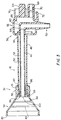
- the tip 16, illustrated in cross section in FIG. 3, may be made from a hard, substantially transparent plastic.
- the tip 16 includes an inner (suction) tube 46 coaxially aligned within an outer (irrigation) tube 48, a flexible, funnel-shaped splash shield 54, and a connector 56.
- the suction tube 46 provides a direct pathway 50 for suction from the tip distal end 32 to a suction source (schematically illustrated as source 18 in Figure 1). Aspirated debris therefore never enters the handpiece 10.
- the annular space 52 between the suction and irrigation tubes 46 and 48 provides a pathway for irrigation fluid.
- the splash shield 54 slidably mounted to the irrigation tube 48, enables treatment to be confined to a localized treatment site.
- the connector 56 at the tip proximal end 36 removably connects the tip 16 to the handpiece 10.
- the suction tube 46 is supported within the irrigation tube 48 at one end by an outlet nozzle 58, and at the other end by an elbow shaped conduit 60.
- the outlet nozzle 58 is in the form of a plurality of circumferentially spaced openings formed in an annular end wall.
- the elbow shaped conduit 60 extends into and downwardly through the connector 56, terminating at a tapered lower end 62 having a plurality of annular ridges 63 (figure 5).
- the suction tube 46 is sealed to both the outlet nozzle 58 and elbow-shaped conduit 60 to form a continuous suction lumen 64 from the tip distal end 32 to the tapered lower end 62 of the elbow 60 to which the suction tubing 20 from a suction source may be connected.
- the elbow shaped conduit 60 is shown as extending from the proximal end of the suction tube 46, it may depend from any part of the suction tube 46. In an alternative embodiment, for example, the suction tube 46 is about half the size as it is in the preferred embodiment and the elbow shaped conduit 60 may connect to the suction tube 46 within the irrigation tube 48.
- the tapered end 62 of the elbow shaped conduit 60 extends through a wall of the irrigation tube 48 for connection with the flexible suction tubing 20.
- the connector 56 has an irrigation fluid chamber 66 that receives fluid from the handpiece irrigation port 30 through an irrigation connector 68. After the fluid is received in the fluid chamber 66, the fluid chamber 66 directs it to the annular space 52, which then directs it through the outlet nozzle 58.
- An O-ring 70 may encircle the irrigation connector 68 to seal the connection between the irrigation connector 68 and the irrigation port 30 on the handpiece.
- a flexible clip 72 may be molded integrally with the connector 56 for engagement with a lip 74 formed along the underside of the handpiece fitting 26.
- a hood 76 extends proximally from the connector 56 to shield the suction and irrigation ports 28 and 30 from irrigation fluid and debris that, in use, may splash back toward the handpiece 10.
- the hood 76 preferably has a partially oblong shape, approximating the shape of the handpiece fitting 26. It extends downwardly about the tip plug 34 and partially about the irrigation connector 68. When the tip 16 is connected to the handpiece 10, the hood 76 covers the top portion of the fitting 26, thus further reducing the risk of splashed fluids contaminating the ports 28 and 30. The rounded top of the hood 76 causes fluids to drip past the sides of the nozzle 26.
- the flexible shield 54 includes a proximal collar 78 and a conical body that diverges in a distal direction to a distal rim 80.
- the collar 78 is slidably mounted to the irrigation tube 48 and has an annular gripping ridge 82 to facilitate gripping the collar 78.
- a plurality of circumferential ridges 84 may be included on the inner surface of the shield 54 to serve as cutting guides for cutting shield 54.
- Vent holes 86 formed in the side of the shield 54 prevent the shield 54 from collapsing under suction and also enable air to mix with the debris aspirated from the site to avoid stagnation of the debris within the shield 54.
- the shield 54 may be made from a flexible, substantially clear plastic that may be shaped during use to conform to the shape and contour of the irrigation site.
- the collar 78 may be secured to the distal end of the tip 16 by both an annular flange 88 (shown in figures 2 and 3) and a discontinuous circumferential ridge 90 formed on the irrigation tube 48.
- the ridge 90 has two discontinuities 92 that enable the shield 54 to be easily forced over the securing ridge 90.
- the shield 54 may be retracted proximally (FIG 2), over the securing ridge 90, by applying a proximal force to either the rim 54 or to the gripping ridge on the collar 78.
- the irrigation tube 48 may be tapered slightly toward the tip distal end 32 to increase the resistance to proximally retracting the shield 54.
- a stop ridge 94 may circumscribe the proximal end of the irrigation tube 48 to prevent the splash shield 54 from being retracted into contact with the connector 56.
- the shower head nozzle 58 is fastened to the tip distal end 32 and includes an end wall 97 and a cylindrical wall 98 extending proximally from the end wall.
- the nozzle 58 serves a number of important functions.
- the shower head nozzle 58 has a plurality of irrigation holes 96 (e.g.. nine) longitudinally formed through the cylindrical wall 98 and end wall 97, and a central suction hole 100.
- the diameter of the central suction hole 100 should have approximately the same diameter as the inner diameter of the suction tube 46 such as, for example, 0.1875 inches (4.81 mm).
- the number, shape, and size of the irrigation holes 96 are selected both to provide a specialized spray pattern for the irrigation fluid and to regulate the force with which the irrigation fluid is emitted from the tip 16. Accordingly, the suction/irrigation tip 16 may be customized to be usable with certain handpieces only. For example, when irrigating an externally exposed wound (e.g., a bed sore), it is preferred that the irrigation fluid be emitted from the tip 16 at a force not exceeding 15 p.s.i. (1 bar).
- the tip 16 have a simple identification means that quickly and easily indicates the tip 16 that corresponds to the handpiece 10 being used.
- the tip connector 56 may be color coded to correlate with the handpiece 10.
- the tip connector 56 to be used with the Simpulse SoloTM may be colored purple
- the tip connector 56 to be used with the Simpulse PlusTM may be colored green.
- the tip connector 56 may be specially shaped to mate only with the fitting 26 of the handpiece 10 with which it is to be used. Therefore, the wrong tip 16 cannot fit into the wrong pump/handpiece 10.
- either the irrigation connector 68 or the tip plug 34 may be provided with a ridge 101 (Fig. 4) or other irregularity, and the corresponding handpiece suction port 28 or irrigation port 30 may be molded to that complimentary shape.
- the connector 56 may only be connected to the corresponding port for a fluid fight fit.
- Fig. 7 illustrates an arrangement by which the handpiece 10 is protected from irrigation fluid and other biological debris that may splash from the irrigation site during use.
- the tip 16 is provided with an protective covering 102 having one end 104 that is heat sealed to the connector 56 and another end 106 that is open.
- the protective covering 102 is sized to fit loosely about the handpiece 10.
- the length of the protective covering 102 preferably is long enough to extend to the bottom end of the handpiece 10. This ensures that the handpiece 10 will remain protected by the protective covering 102 even though the protective covering 102 might shift somewhat relative to the handpiece 10.
- An elastic band may be connected about the protective covering open end 106 to provide a secure fit about the bottom end of the handpiece 10.
- the protective covering 102 is can be made from a thin, flexible, substantially transparent polymeric material, such as a low density polyethylene having a thickness of about 0.001 inch (.04 mm). It is dimensioned so that it will maintain a loose fit about the handpiece 10.
- the flexibility and transparent nature of the polymeric protective covering 102 enables the attendant to effectively operate all the controls on the handpiece 10 through the protective covering.
- Fig. 8 shows a second arrangement by which both the handpiece 10 and attendant's arm are protected from debris that splashes from the site.
- the tip 16 is provided with a long protective covering 108 having one end 110 that is heat sealed to the connector 56 and another end 112 that is open.
- the long protective covering 108 is sized to fit loosely about the handpiece 10 so that the attendant may operate the handpiece 10 from within the long protective covering 108
- the length of the protective covering 108 preferably is three times the length of the handpiece 10 so that the open end 112 will extend approximately to the attendant's elbow 114. This ensures that both the handpiece 10 and attendant's arm will be protected from debris that splashes from the site.
- the long protective covering 108 may be made from a thin, flexible, substantially transparent polymeric material, such as a low density polyethylene having a thickness of 254 mm (about 0.001 inch). It is dimensioned so that the attendant's hand will easily fit inside the protective covering 108 to operate the handpiece 10. The flexibility and transparent nature of the long protective covering 108 enables the attendant to effectively operate all the controls on the handpiece 10 from inside and outside the protective covering 108.
- the tip 16 When in use, the tip 16 is connected to the handpiece 10 and the flexible suction tubing 20 is connected to the tapered lower end 62 of the elbow shaped conduit 60.
- the handpiece suction tube 22 remains unused. Since the tip 16 is connected to the handpiece 10, the tip plug 34 sealingly connects to the handpiece suction port 28 and the irrigation connector 68 connects to the handpiece irrigation port 30.
- the shield 54 may be positioned at the tip distal end 32 and the rim 80 may positioned at the local irrigation site. If desired, either of the flexible protective coverings 102 or 108 may be disposed over and about the handpiece 10. The user may then simultaneously irrigate and aspirate the site.
- the attendant may retract the shield 54 to put the shower head nozzle 58 directly against, or very close proximity to, the irrigated site.
- the large cross-sectional area of the suction tube 46 reduces the possibility of clogging.
- the tip 16 and protective covering 102 or 108 are discarded and the two prong plug 38 is inserted into the suction and irrigation ports 28, 30 to ensure that the handpiece 10 remains aseptic.
- the handpiece 10 may be reused at a later time by removing the two prong plug 38 and inserting a new suction irrigation tip 16.
Landscapes
- Health & Medical Sciences (AREA)
- Heart & Thoracic Surgery (AREA)
- Veterinary Medicine (AREA)
- Anesthesiology (AREA)
- Hematology (AREA)
- Life Sciences & Earth Sciences (AREA)
- Animal Behavior & Ethology (AREA)
- General Health & Medical Sciences (AREA)
- Public Health (AREA)
- Engineering & Computer Science (AREA)
- Biomedical Technology (AREA)
- Pulmonology (AREA)
- Vascular Medicine (AREA)
- Physics & Mathematics (AREA)
- Oral & Maxillofacial Surgery (AREA)
- Surgery (AREA)
- Fluid Mechanics (AREA)
- External Artificial Organs (AREA)
- Surgical Instruments (AREA)
- Infusion, Injection, And Reservoir Apparatuses (AREA)
- Endoscopes (AREA)
Description
Claims (19)
- A detachable suction tip (16) for use with a suction handpiece (10), the handpiece having a suction lumen (22) extending therethrough for removing irrigation fluid from an irrigation site, the suction lumen (22) terminating at a suction port (28) formed through a fitting (26) at the distal end of the handpiece, the tip including a suction tube (46) having a distal end for aspirating irrigation fluid from the irrigation site, and a connector (56) for mechanically connecting the tip to the fitting (26) of the handpiece, characterized by the suction tube (46) having a fluid bypass conduit (60,64) sealingly connected to a proximal end of the suction tube (46) within the detachable tip and extending to an external end (62) for channeling aspirated irrigation fluid directly to a suction source (18) so that aspirated fluid within the suction tube (46) does not communicate with the handpiece suction lumen; and the connector (56) also having a plug (34) positioned to engage into the suction port (28) for sealing the suction lumen (22) in the handpiece when the tip is connected to the handpiece fitting (26).
- A tip as defined in Claim 1 further comprising an irrigation tube (48) for directing the irrigation fluid to the irrigation site.
- A tip as defined in Claim 2, wherein the connector (56) is further adapted to connect the irrigation tube (48) to an irrigation lumen (24) of the handpiece (10) to provide fluid communication therebetween.
- A tip as defined in Claim 2, wherein the suction tube (46) is within the irrigation tube (48).
- A tip as defined by Claim 4, wherein the fluid bypass conduit (60,64) passes through a wall of the irrigation tube (48).
- A tip as defined by any one of Claims 2 to 5, wherein the connector (56) has an adjacent chamber (66) for directing the irrigation fluid to the irrigation tube (48) and wherein the fluid bypass path (60,64) passes through the chamber (66).
- A tip as defined by any one of Claims 2 to 6, wherein the irrigation tube (48) and suction tube (46) are coaxially aligned.
- A tip as defined by any one of Claims 1 to 7 further comprising a splash shield (54) slidably mounted on the tip.
- A tip as defined by any one of Claims 1 to 8 further comprising a fluid deflecting hood (76) extending from the connector (56) to deflect splashed irrigation fluid away from the handpiece (10).
- A tip as defined by any one of Claims 1 to 9 further comprising a protective covering (102) fastened to the tip and arranged for covering the handpiece (10).
- A tip as defined by any one of Claims 1 to 10, wherein the fluid bypass conduit (60,64) terminates at an open end (62) suitable for connection to a suction source (18).
- A tip as defined by any one of Claims 1 to 11, wherein the suction tube (46) has a tube segment arranged to divert aspirated fluid away from the distal end of the handpiece (10).
- A method for assembling an irrigation device using a tip according to Claim 2, the method including:providing a handpiece (10) defining a handpiece irrigation lumen (24) and a handpiece suction lumen (22);connecting the handpiece irrigation lumen (24) to an irrigation fluid source (12);detachably connecting said tip (16) to a distal end of the handpiece (10), to place the irrigation tube (48) of the tip (16) in fluid communication with the irrigation lumen (24);plugging the handpiece suction lumen (22) with the plug (34); andconnecting the bypass fluid conduit (60,64) of the tip (16) to a suction source to allow fluid to be aspirated from the tip suction tube (46) via said bypass fluid conduit (60,64).
- An apparatus for irrigating an irrigation site comprising a handpiece (10) having an irrigation lumen (24) extending therethrough and a tip (16) according to Claim 2, detachably connected to said handpiece (10), so that the fluid bypass conduit bypasses the handpiece (10) to prevent aspirated fluid within the suction tube (46) from communicating with the interior of the handpiece.
- The apparatus as defined by Claim 14, wherein the connector (56) comprises a connecting tube (68) in fluid communication with the irrigation tube, the connecting tube removably connecting the irrigation tube to the irrigation lumen in the handpiece, and the plug (34) sealing a suction lumen (22) in the handpiece (10).
- The apparatus as defined by Claim 14 or 15 further comprising a flexible protective covering (102,108) connected to the tip, the protective covering being disposed about and surrounding the proximal end of the tip and the handpiece (10), and extending at least to the lower end of the handpiece (10).
- The apparatus as defined by Claim 16, wherein the protective covering (108) has a length of approximately three times the length of the handpiece.
- A method of disassembling the apparatus of Claim 15 comprising removing the tip (16) from the handpiece (10), inserting a plug (38) having two projections (40,44) (40) in the handpiece suction lumen (22) and in the handpiece irrigation lumen (24).
- The method as defined by Claim 18 further comprising removing the plug (38) from the handpiece suction lumen (22) and from the handpiece irrigation lumen (24) and connecting a second tip according to claim 2 to the handpiece (10).
Applications Claiming Priority (3)
| Application Number | Priority Date | Filing Date | Title |
|---|---|---|---|
| US08/665,467 US6200292B1 (en) | 1996-06-18 | 1996-06-18 | Suction and irrigation handpiece and tip |
| US665467 | 1996-06-18 | ||
| PCT/US1997/005762 WO1997048427A2 (en) | 1996-06-18 | 1997-04-07 | Suction and irrigation handpiece and tip |
Publications (2)
| Publication Number | Publication Date |
|---|---|
| EP0906130A2 EP0906130A2 (en) | 1999-04-07 |
| EP0906130B1 true EP0906130B1 (en) | 2005-06-15 |
Family
ID=24670228
Family Applications (1)
| Application Number | Title | Priority Date | Filing Date |
|---|---|---|---|
| EP97920203A Expired - Lifetime EP0906130B1 (en) | 1996-06-18 | 1997-04-07 | Suction and irrigation handpiece and tip |
Country Status (7)
| Country | Link |
|---|---|
| US (2) | US6200292B1 (en) |
| EP (1) | EP0906130B1 (en) |
| JP (1) | JP2001503649A (en) |
| AU (1) | AU737808B2 (en) |
| DE (1) | DE69733558T2 (en) |
| ES (1) | ES2243992T3 (en) |
| WO (1) | WO1997048427A2 (en) |
Cited By (2)
| Publication number | Priority date | Publication date | Assignee | Title |
|---|---|---|---|---|
| US9993585B2 (en) | 2011-11-11 | 2018-06-12 | University Of Virginia Patent Foundation | Method suction device and related method thereof |
| USD896364S1 (en) | 2016-01-22 | 2020-09-15 | Medline Industries, Inc. | Irrigator |
Families Citing this family (75)
| Publication number | Priority date | Publication date | Assignee | Title |
|---|---|---|---|---|
| US6746419B1 (en) * | 1993-04-19 | 2004-06-08 | Stryker Corporation | Irrigation handpiece with built in pulsing pump |
| US6213970B1 (en) * | 1993-12-30 | 2001-04-10 | Stryker Corporation | Surgical suction irrigation |
| US6099494A (en) * | 1997-08-20 | 2000-08-08 | Stryker Corporation | Pulsed irrigator useful for surgical and medical procedures |
| US6293929B1 (en) | 1997-09-02 | 2001-09-25 | Steven M. Smith | Wound irrigation apparatus |
| US6402724B1 (en) | 1997-09-09 | 2002-06-11 | Wolfe Tory Medical, Inc. | Wound irrigation shield |
| US6520982B1 (en) * | 2000-06-08 | 2003-02-18 | Kci Licensing, Inc. | Localized liquid therapy and thermotherapy device |
| US6652488B1 (en) | 2000-09-11 | 2003-11-25 | Stryker Corporation | Surgical suction irrigator |
| US6962298B1 (en) * | 2000-11-09 | 2005-11-08 | Martin Kenneth L | Showerhead |
| USD453376S1 (en) | 2001-04-16 | 2002-02-05 | Welch Allyn, Inc. | Body cavity irrigation syringe |
| US20080288178A1 (en) * | 2001-08-24 | 2008-11-20 | Applera Corporation | Sequencing system with memory |
| US7527608B2 (en) * | 2002-08-12 | 2009-05-05 | Lma North America, Inc. | Medication infusion and aspiration system and method |
| US20040106907A1 (en) * | 2002-10-02 | 2004-06-03 | Shih-Ta Liu | Device for sucking body and method thereof |
| CN1600380B (en) * | 2003-09-23 | 2010-04-21 | 碧波庭国际有限公司 | Intermittent cupping device |
| AT412972B (en) * | 2003-10-14 | 2005-09-26 | Bierbaumer Hans Peter Dr | DEVICE FOR CONVERTING ENERGY |
| AU2004293815B2 (en) * | 2003-11-20 | 2010-07-22 | The Henry M. Jackson Foundation For The Advancement Of Military Medicine, Inc. | Portable hand pump for evacuation of fluids |
| US7578808B2 (en) * | 2004-02-05 | 2009-08-25 | Masahiro Watanabe | Suction-cleansing device and cleansing apparatus having the same |
| US6852093B1 (en) * | 2004-05-10 | 2005-02-08 | Alcon, Inc. | Surgical method and apparatus |
| US20060058723A1 (en) * | 2004-09-15 | 2006-03-16 | Pratt William R | Apparatus and method for cleaning a surgically prepared bone surface |
| US8337475B2 (en) | 2004-10-12 | 2012-12-25 | C. R. Bard, Inc. | Corporeal drainage system |
| USD533274S1 (en) | 2004-10-12 | 2006-12-05 | Allegiance Corporation | Handle for surgical suction-irrigation device |
| ITPD20040252A1 (en) * | 2004-10-14 | 2005-01-14 | Bidoia Sas Di Gianfranco Bidoi | SURGICAL IRRIGATOR |
| EP1909863A1 (en) | 2005-07-24 | 2008-04-16 | Carmeli Adahan | Wound closure and drainage system |
| US8177772B2 (en) * | 2005-09-26 | 2012-05-15 | C. R. Bard, Inc. | Catheter connection systems |
| US7540860B2 (en) * | 2006-01-23 | 2009-06-02 | Keith Stamler | Wound irrigation splashback shield |
| WO2008005996A2 (en) * | 2006-07-05 | 2008-01-10 | Stryker Corporation | Medical/surgical lavage system capable of selectively and sequentially discharging either a base solution or a solution which includes a therapeutic agent |
| US8827945B2 (en) | 2006-11-06 | 2014-09-09 | Aardvark Medical, Inc. | Irrigation and aspiration devices and methods |
| US20080146991A1 (en) * | 2006-12-18 | 2008-06-19 | Chris Hernandez | Hand operated dispenser for surgical irrigation fluids |
| JP5634863B2 (en) | 2007-05-22 | 2014-12-03 | メデラ ホールディング アーゲー | Drainage pump unit |
| US20090061198A1 (en) * | 2007-09-04 | 2009-03-05 | Khambete Surendra S | Polyester padding for gymnasium |
| US8986253B2 (en) | 2008-01-25 | 2015-03-24 | Tandem Diabetes Care, Inc. | Two chamber pumps and related methods |
| WO2009097451A1 (en) | 2008-01-29 | 2009-08-06 | Edge Systems Corporation | Apparatus and method for treating the skin |
| US8408421B2 (en) | 2008-09-16 | 2013-04-02 | Tandem Diabetes Care, Inc. | Flow regulating stopcocks and related methods |
| CA2737461A1 (en) | 2008-09-19 | 2010-03-25 | Tandem Diabetes Care, Inc. | Solute concentration measurement device and related methods |
| US20100249703A1 (en) * | 2009-03-27 | 2010-09-30 | Cliff John A | Sterilizable vacuum handpiece |
| EP2724739B1 (en) | 2009-07-30 | 2015-07-01 | Tandem Diabetes Care, Inc. | Portable infusion pump system |
| USD631544S1 (en) * | 2009-08-18 | 2011-01-25 | Joseph Wayne Kraft | Anesthesia injection cone |
| US20110112515A1 (en) * | 2009-11-06 | 2011-05-12 | Stiehl James B | Actuated self unplugging surgical sucker wand |
| US9282995B2 (en) | 2011-12-22 | 2016-03-15 | Previvo Genetics, Llc | Recovery and processing of human embryos formed in vivo |
| US9216037B2 (en) | 2013-06-21 | 2015-12-22 | Previvo Genetics, Llc | Uterine lavage for embryo retrieval |
| US20150272622A1 (en) | 2011-12-22 | 2015-10-01 | Previvo Genetics, Llc | Recovery and processing of human embryos formed in vivo |
| US8721595B2 (en) | 2012-05-11 | 2014-05-13 | Stiehl Technologies, Llc | Surgical suction wand |
| US20130304000A1 (en) * | 2012-05-14 | 2013-11-14 | Christian James Pentell | Body piercing cleansing and sanitation device |
| US9180242B2 (en) | 2012-05-17 | 2015-11-10 | Tandem Diabetes Care, Inc. | Methods and devices for multiple fluid transfer |
| US9173998B2 (en) | 2013-03-14 | 2015-11-03 | Tandem Diabetes Care, Inc. | System and method for detecting occlusions in an infusion pump |
| US9693896B2 (en) | 2013-03-15 | 2017-07-04 | Novartis Ag | Systems and methods for ocular surgery |
| US9981080B2 (en) | 2013-08-09 | 2018-05-29 | Centurion Medical Products Corporation | Disposable wound irrigation device and associated method of use |
| CN103480058B (en) * | 2013-09-24 | 2015-08-26 | 湖南瀚德微创医疗科技有限公司 | Flexible punch tip |
| CN104287666B (en) * | 2014-09-22 | 2016-08-24 | 京东方科技集团股份有限公司 | A kind of clean body head and clean body instrument |
| KR101546898B1 (en) * | 2014-11-17 | 2015-08-24 | 주식회사 갈렙 | Irrigator for washing while surgery operation |
| US10179229B2 (en) | 2014-12-23 | 2019-01-15 | Edge Systems Llc | Devices and methods for treating the skin using a porous member |
| US11266776B2 (en) | 2015-10-30 | 2022-03-08 | Medtronic Xomed, Inc. | Method and apparatus for irrigation |
| US20170119953A1 (en) * | 2015-10-30 | 2017-05-04 | Medtronic Xomed, Inc. | Method and Apparatus for Irrigation |
| AU2017299466B2 (en) | 2016-07-18 | 2022-07-14 | Merit Medical Systems, Inc. | Inflatable radial artery compression device |
| US10799152B2 (en) | 2016-08-11 | 2020-10-13 | Medtronic Xomed, Inc. | System and method for motion detection and accounting |
| WO2018158889A1 (en) * | 2017-03-01 | 2018-09-07 | 株式会社ニフコ | Wound area washing device |
| US11980394B2 (en) | 2017-06-05 | 2024-05-14 | Bateman Bottle, Llc | Device for removal of implants and associated method of use |
| US11026715B2 (en) | 2017-09-28 | 2021-06-08 | John Mayberry | Chest cavity suction medical apparatus and method |
| JP7546851B2 (en) * | 2018-08-21 | 2024-09-09 | ザ リージェンツ オブ ザ ユニヴァーシティー オブ カリフォルニア | Suction head for vacuum-operated surgical graspers |
| WO2020163343A1 (en) | 2019-02-04 | 2020-08-13 | The Regents Of The University Of Michigan | Device and method for wound irrigation and debridement |
| USD1024310S1 (en) | 2019-03-28 | 2024-04-23 | Bateman Bottle, Llc | Implant removal device |
| US11311663B2 (en) | 2019-11-27 | 2022-04-26 | PurePierce Inc. | Device for cleaning two-sided bodily punctures |
| US11291474B2 (en) | 2020-01-06 | 2022-04-05 | Ed F. Nicolas | Skin treatment tool applicator tip |
| CN111437445A (en) * | 2020-04-10 | 2020-07-24 | 北京鸿鹄高翔科技开发有限公司 | Disposable flushing and sucking drainage tube and use method thereof |
| US12484911B2 (en) | 2020-08-13 | 2025-12-02 | Merit Medical Systems, Inc. | Inflatable radial artery compression device with cinching wristband and method of use |
| CN113288784B (en) * | 2021-06-11 | 2023-03-31 | 中国人民解放军陆军军医大学第一附属医院 | Lacrimal passage irrigation water collecting device |
| US12426864B2 (en) | 2021-06-18 | 2025-09-30 | Merit Medical Systems, Inc. | Hemostasis devices and methods of use |
| USD1065551S1 (en) | 2021-09-10 | 2025-03-04 | Hydrafacial Llc | Skin treatment device |
| USD1116120S1 (en) | 2021-10-11 | 2026-03-03 | Hydrafacial Llc | Skin treatment device |
| US12090263B1 (en) * | 2022-01-10 | 2024-09-17 | Squlpt Management LLC | Liposuction apparatus |
| USD1112778S1 (en) | 2022-03-04 | 2026-02-10 | Hydrafacial Llc | Light therapy device for skin care |
| USD1084369S1 (en) | 2023-02-10 | 2025-07-15 | Hydrafacial Llc | Skin treatment tip |
| EP4661928A1 (en) * | 2023-02-10 | 2025-12-17 | HydraFacial LLC | Tips for skin treatment devices and systems |
| EP4724133A1 (en) * | 2023-06-12 | 2026-04-15 | Baptist Health South Florida, Inc. | Cap for intraoperative suction device |
| CN118512681B (en) * | 2024-07-22 | 2024-10-22 | 德韵健(山东)医疗科技有限公司 | Splash-proof flushing device for nursing |
| DE102024124876A1 (en) * | 2024-08-30 | 2026-03-05 | Rz-Medizintechnik Gmbh | Medical continuous flushing system |
Family Cites Families (29)
| Publication number | Priority date | Publication date | Assignee | Title |
|---|---|---|---|---|
| US517274A (en) | 1894-03-27 | Ellick h | ||
| US906711A (en) | 1907-10-30 | 1908-12-15 | Hiram Mcclung Hill | Syringe. |
| US1178898A (en) | 1915-11-02 | 1916-04-11 | Harold W Young | Irrigator. |
| US1889425A (en) | 1931-03-02 | 1932-11-29 | C M Sorensen Co Inc | Medical douche |
| US2531793A (en) | 1948-04-15 | 1950-11-28 | Sulek Steve | Hygienic syringe |
| FR1047107A (en) | 1951-12-26 | 1953-12-11 | Cannula or mask for injections, instillations and similar applications under vacuum | |
| DE1816838C3 (en) | 1968-01-12 | 1973-08-16 | Svenska Utvecklings Ab | DEVICE FOR WASHING PEOPLE, ESPECIALLY BEDDED PATIENTS |
| US3735751A (en) | 1971-06-08 | 1973-05-29 | S Katz | Lavage and cytology instrument |
| GB8504906D0 (en) | 1985-02-26 | 1985-03-27 | Deane G | Suction irrigation apparatus |
| US4692140A (en) * | 1985-07-01 | 1987-09-08 | Snyder Laboratories, Inc. | Lavage/suction tip with dual splash shield |
| FR2610511A1 (en) * | 1987-02-06 | 1988-08-12 | Issalene Robert | DENTAL INSTRUMENT AND CANNULAS FOR ASPIRATION, CLEANING, DRYING AND LIGHTING IN THE MOUTH |
| US4815462A (en) * | 1987-04-06 | 1989-03-28 | Clark Vickie J | Lipectomy device |
| US4776840A (en) * | 1987-09-28 | 1988-10-11 | Alteron, Inc. | Hand-held medical evacuator and irrigation device |
| US4810194A (en) | 1987-11-04 | 1989-03-07 | Snedden John E | Disposable antiseptic dental shield |
| US5046486A (en) * | 1989-01-13 | 1991-09-10 | Stryker Corporation | Compact pulsing pump for irrigation handpiece |
| US5030202A (en) | 1989-05-12 | 1991-07-09 | Equibov Ltd. | Lavage system |
| US5170779A (en) | 1991-01-22 | 1992-12-15 | Ginsberg Irwin A | Automated ear cleansing device |
| US5527275A (en) * | 1991-01-22 | 1996-06-18 | Ginsberg; Irwin A. | Automated ear cleansing device |
| US5302124A (en) | 1993-03-25 | 1994-04-12 | Pinnacle Products, Inc. | Disposable protective sleeve for dental apparatus such as light curing guns |
| US5470305A (en) * | 1993-04-19 | 1995-11-28 | Stryker Corporation | Irrigation handpiece with built in pulsing pump |
| BR9302813A (en) | 1993-07-09 | 1993-11-23 | Jose Da Silva Bueno Neto | DISPOSABLE EXTERNAL PROTECTOR FOR DENTAL PENS |
| US5354267A (en) * | 1993-09-20 | 1994-10-11 | Vital Signs Inc. | Irrigation and suction apparatus |
| US5460604A (en) | 1993-11-29 | 1995-10-24 | Stryker Corporation | Surgical irrigation apparatus |
| US5464390A (en) | 1993-11-29 | 1995-11-07 | Stryker Corporation | Surgical multiorifice irrigation apparatus |
| US5488949A (en) | 1994-11-07 | 1996-02-06 | Kreifels; Kelly E. | Dual suction device |
| US5496290A (en) | 1994-11-23 | 1996-03-05 | Ackrad Laboratories, Inc. | Wound irrigation splash shield |
| US5746721A (en) * | 1995-02-15 | 1998-05-05 | C.R. Bard, Inc. | Pulsed lavage pump with integral power source and variable flow control |
| US5941851A (en) * | 1996-07-12 | 1999-08-24 | C.R. Bard, Inc. | Pulsed lavage handpiece with improved handle |
| US5735833A (en) * | 1996-12-11 | 1998-04-07 | Bristol-Myers Squibb Co. | Lavage tip |
-
1996
- 1996-06-18 US US08/665,467 patent/US6200292B1/en not_active Expired - Lifetime
-
1997
- 1997-04-07 WO PCT/US1997/005762 patent/WO1997048427A2/en not_active Ceased
- 1997-04-07 JP JP50292598A patent/JP2001503649A/en active Pending
- 1997-04-07 ES ES97920203T patent/ES2243992T3/en not_active Expired - Lifetime
- 1997-04-07 EP EP97920203A patent/EP0906130B1/en not_active Expired - Lifetime
- 1997-04-07 DE DE69733558T patent/DE69733558T2/en not_active Expired - Lifetime
- 1997-04-07 AU AU24455/97A patent/AU737808B2/en not_active Expired
-
2000
- 2000-11-02 US US09/704,895 patent/US6485452B1/en not_active Expired - Lifetime
Cited By (2)
| Publication number | Priority date | Publication date | Assignee | Title |
|---|---|---|---|---|
| US9993585B2 (en) | 2011-11-11 | 2018-06-12 | University Of Virginia Patent Foundation | Method suction device and related method thereof |
| USD896364S1 (en) | 2016-01-22 | 2020-09-15 | Medline Industries, Inc. | Irrigator |
Also Published As
| Publication number | Publication date |
|---|---|
| EP0906130A2 (en) | 1999-04-07 |
| WO1997048427A3 (en) | 1998-03-05 |
| WO1997048427A2 (en) | 1997-12-24 |
| ES2243992T3 (en) | 2005-12-01 |
| US6200292B1 (en) | 2001-03-13 |
| AU2445597A (en) | 1998-01-07 |
| AU737808B2 (en) | 2001-08-30 |
| DE69733558D1 (en) | 2005-07-21 |
| US6485452B1 (en) | 2002-11-26 |
| DE69733558T2 (en) | 2006-05-11 |
| JP2001503649A (en) | 2001-03-21 |
Similar Documents
| Publication | Publication Date | Title |
|---|---|---|
| US6200292B1 (en) | Suction and irrigation handpiece and tip | |
| CA2258658C (en) | Suction and irrigation handpiece and tip with retractable splash shield | |
| US5792098A (en) | Suction and irrigation handpiece and tip with detachable tube | |
| US11071808B2 (en) | Irrigation fluid containment systems | |
| US5827218A (en) | Surgical suction pool tip | |
| US4692140A (en) | Lavage/suction tip with dual splash shield | |
| US5941859A (en) | Wound irrigation shield with fluid scavenging | |
| US6712757B2 (en) | Endoscope sleeve and irrigation device | |
| US5083561A (en) | Tracheal suction catheter | |
| WO1995001755A1 (en) | Disposable aspiration tip for a cautery handpiece | |
| JPH08500045A (en) | Disposable endoscopic sheath | |
| CA2277126A1 (en) | System for aspirating and irrigating tract wounds | |
| US5957928A (en) | Handpiece for irrigation and aspiration during eye surgery and a method for manufacturing such a handpiece | |
| CA2258657C (en) | Suction and irrigation handpiece and tip | |
| AU9522701A (en) | Suction and irrigation handpiece and tip | |
| US20030204200A1 (en) | Splash shield for use with debridement devices | |
| AU772043B2 (en) | Medical irrigation system | |
| RU16258U1 (en) | INSTALLATION FOR WASHING ALMONDIN LACOURS |
Legal Events
| Date | Code | Title | Description |
|---|---|---|---|
| PUAI | Public reference made under article 153(3) epc to a published international application that has entered the european phase |
Free format text: ORIGINAL CODE: 0009012 |
|
| 17P | Request for examination filed |
Effective date: 19990114 |
|
| AK | Designated contracting states |
Kind code of ref document: A2 Designated state(s): DE ES FR GB IT |
|
| RIN1 | Information on inventor provided before grant (corrected) |
Inventor name: TREMAINE, LAURENCE Inventor name: DAROIS, ROGER Inventor name: ALBRECHT, STEPHEN Inventor name: SAKAL, ROBERT Inventor name: FRENCH, GLEN |
|
| RIN1 | Information on inventor provided before grant (corrected) |
Inventor name: TREMAINE, LAURENCE Inventor name: DAROIS, ROGER Inventor name: ALBRECHT, STEPHEN Inventor name: SAKAL, ROBERT Inventor name: FRENCH, GLEN |
|
| 17Q | First examination report despatched |
Effective date: 20030131 |
|
| GRAP | Despatch of communication of intention to grant a patent |
Free format text: ORIGINAL CODE: EPIDOSNIGR1 |
|
| GRAS | Grant fee paid |
Free format text: ORIGINAL CODE: EPIDOSNIGR3 |
|
| GRAA | (expected) grant |
Free format text: ORIGINAL CODE: 0009210 |
|
| AK | Designated contracting states |
Kind code of ref document: B1 Designated state(s): DE ES FR GB IT |
|
| REG | Reference to a national code |
Ref country code: GB Ref legal event code: FG4D |
|
| REF | Corresponds to: |
Ref document number: 69733558 Country of ref document: DE Date of ref document: 20050721 Kind code of ref document: P |
|
| REG | Reference to a national code |
Ref country code: ES Ref legal event code: FG2A Ref document number: 2243992 Country of ref document: ES Kind code of ref document: T3 |
|
| ET | Fr: translation filed | ||
| PLBE | No opposition filed within time limit |
Free format text: ORIGINAL CODE: 0009261 |
|
| STAA | Information on the status of an ep patent application or granted ep patent |
Free format text: STATUS: NO OPPOSITION FILED WITHIN TIME LIMIT |
|
| 26N | No opposition filed |
Effective date: 20060316 |
|
| PGFP | Annual fee paid to national office [announced via postgrant information from national office to epo] |
Ref country code: IT Payment date: 20070521 Year of fee payment: 11 |
|
| PG25 | Lapsed in a contracting state [announced via postgrant information from national office to epo] |
Ref country code: IT Free format text: LAPSE BECAUSE OF NON-PAYMENT OF DUE FEES Effective date: 20080407 |
|
| REG | Reference to a national code |
Ref country code: FR Ref legal event code: PLFP Year of fee payment: 19 |
|
| PGFP | Annual fee paid to national office [announced via postgrant information from national office to epo] |
Ref country code: ES Payment date: 20150310 Year of fee payment: 19 |
|
| PGFP | Annual fee paid to national office [announced via postgrant information from national office to epo] |
Ref country code: GB Payment date: 20150401 Year of fee payment: 19 Ref country code: DE Payment date: 20150331 Year of fee payment: 19 |
|
| PGFP | Annual fee paid to national office [announced via postgrant information from national office to epo] |
Ref country code: FR Payment date: 20150408 Year of fee payment: 19 |
|
| REG | Reference to a national code |
Ref country code: DE Ref legal event code: R119 Ref document number: 69733558 Country of ref document: DE |
|
| GBPC | Gb: european patent ceased through non-payment of renewal fee |
Effective date: 20160407 |
|
| REG | Reference to a national code |
Ref country code: FR Ref legal event code: ST Effective date: 20161230 |
|
| PG25 | Lapsed in a contracting state [announced via postgrant information from national office to epo] |
Ref country code: GB Free format text: LAPSE BECAUSE OF NON-PAYMENT OF DUE FEES Effective date: 20160407 Ref country code: DE Free format text: LAPSE BECAUSE OF NON-PAYMENT OF DUE FEES Effective date: 20161101 Ref country code: FR Free format text: LAPSE BECAUSE OF NON-PAYMENT OF DUE FEES Effective date: 20160502 |
|
| REG | Reference to a national code |
Ref country code: ES Ref legal event code: FD2A Effective date: 20180507 |
|
| PG25 | Lapsed in a contracting state [announced via postgrant information from national office to epo] |
Ref country code: ES Free format text: LAPSE BECAUSE OF NON-PAYMENT OF DUE FEES Effective date: 20160408 |