EP0906053B1 - Remote controllable medical pumping apparatus - Google Patents
Remote controllable medical pumping apparatus Download PDFInfo
- Publication number
- EP0906053B1 EP0906053B1 EP97909903A EP97909903A EP0906053B1 EP 0906053 B1 EP0906053 B1 EP 0906053B1 EP 97909903 A EP97909903 A EP 97909903A EP 97909903 A EP97909903 A EP 97909903A EP 0906053 B1 EP0906053 B1 EP 0906053B1
- Authority
- EP
- European Patent Office
- Prior art keywords
- pressure
- signal
- preferred
- remote site
- sensing
- Prior art date
- Legal status (The legal status is an assumption and is not a legal conclusion. Google has not performed a legal analysis and makes no representation as to the accuracy of the status listed.)
- Expired - Lifetime
Links
- 238000005086 pumping Methods 0.000 title claims description 16
- 230000004044 response Effects 0.000 claims description 6
- 239000012530 fluid Substances 0.000 description 8
- 238000010586 diagram Methods 0.000 description 4
- 238000007781 pre-processing Methods 0.000 description 4
- 206010051055 Deep vein thrombosis Diseases 0.000 description 3
- 206010047249 Venous thrombosis Diseases 0.000 description 3
- 230000015572 biosynthetic process Effects 0.000 description 3
- 238000013022 venting Methods 0.000 description 3
- MWUXSHHQAYIFBG-UHFFFAOYSA-N Nitric oxide Chemical compound O=[N] MWUXSHHQAYIFBG-UHFFFAOYSA-N 0.000 description 2
- 230000017531 blood circulation Effects 0.000 description 2
- 230000003511 endothelial effect Effects 0.000 description 2
- 238000001356 surgical procedure Methods 0.000 description 2
- 210000003462 vein Anatomy 0.000 description 2
- 208000005189 Embolism Diseases 0.000 description 1
- 206010020565 Hyperaemia Diseases 0.000 description 1
- 208000001435 Thromboembolism Diseases 0.000 description 1
- 208000007536 Thrombosis Diseases 0.000 description 1
- 239000008280 blood Substances 0.000 description 1
- 210000004369 blood Anatomy 0.000 description 1
- 244000309466 calf Species 0.000 description 1
- 230000006835 compression Effects 0.000 description 1
- 238000007906 compression Methods 0.000 description 1
- 230000007812 deficiency Effects 0.000 description 1
- 230000000916 dilatatory effect Effects 0.000 description 1
- 230000006870 function Effects 0.000 description 1
- 238000011540 hip replacement Methods 0.000 description 1
- 230000002401 inhibitory effect Effects 0.000 description 1
- 208000014674 injury Diseases 0.000 description 1
- 238000013150 knee replacement Methods 0.000 description 1
- 239000004973 liquid crystal related substance Substances 0.000 description 1
- 239000000463 material Substances 0.000 description 1
- 238000012544 monitoring process Methods 0.000 description 1
- 230000000399 orthopedic effect Effects 0.000 description 1
- 230000002093 peripheral effect Effects 0.000 description 1
- 229920003023 plastic Polymers 0.000 description 1
- 239000004033 plastic Substances 0.000 description 1
- 229920006264 polyurethane film Polymers 0.000 description 1
- 229920000915 polyvinyl chloride Polymers 0.000 description 1
- 239000004800 polyvinyl chloride Substances 0.000 description 1
- 238000003825 pressing Methods 0.000 description 1
- 238000012545 processing Methods 0.000 description 1
- 230000002035 prolonged effect Effects 0.000 description 1
- 230000002685 pulmonary effect Effects 0.000 description 1
- 230000002040 relaxant effect Effects 0.000 description 1
- 230000004936 stimulating effect Effects 0.000 description 1
- 230000000638 stimulation Effects 0.000 description 1
- 230000001225 therapeutic effect Effects 0.000 description 1
- 238000012546 transfer Methods 0.000 description 1
- 230000008733 trauma Effects 0.000 description 1
- 210000000689 upper leg Anatomy 0.000 description 1
- 229940124549 vasodilator Drugs 0.000 description 1
- 239000003071 vasodilator agent Substances 0.000 description 1
- 201000002282 venous insufficiency Diseases 0.000 description 1
Images

Classifications
-
- A—HUMAN NECESSITIES
- A61—MEDICAL OR VETERINARY SCIENCE; HYGIENE
- A61H—PHYSICAL THERAPY APPARATUS, e.g. DEVICES FOR LOCATING OR STIMULATING REFLEX POINTS IN THE BODY; ARTIFICIAL RESPIRATION; MASSAGE; BATHING DEVICES FOR SPECIAL THERAPEUTIC OR HYGIENIC PURPOSES OR SPECIFIC PARTS OF THE BODY
- A61H9/00—Pneumatic or hydraulic massage
- A61H9/005—Pneumatic massage
- A61H9/0078—Pneumatic massage with intermittent or alternately inflated bladders or cuffs
-
- A—HUMAN NECESSITIES
- A61—MEDICAL OR VETERINARY SCIENCE; HYGIENE
- A61H—PHYSICAL THERAPY APPARATUS, e.g. DEVICES FOR LOCATING OR STIMULATING REFLEX POINTS IN THE BODY; ARTIFICIAL RESPIRATION; MASSAGE; BATHING DEVICES FOR SPECIAL THERAPEUTIC OR HYGIENIC PURPOSES OR SPECIFIC PARTS OF THE BODY
- A61H2205/00—Devices for specific parts of the body
- A61H2205/12—Feet
Definitions
- This invention relates to a remote controllable medical pumping apparatus and more particularly, but not by way of limitation, to a medical apparatus that is capable of controlling from a local site application of compressive pressures to a part of the human body at a remote site.
- EDRF Endothelial Derived Relaxing Factor
- thromboembolism and pulmonary emboli can result from trauma (such as produced by certain surgeries) or from prolonged venous stasis. These and other factors are known to contribute to the formation of Deep Vein Thrombosis (DVT) in the deep proximal veins of a patient undergoing hip/knee replacement and/or other orthopedic surgery.
- DVT Deep Vein Thrombosis
- pneumatic compression devices have been utilized on a part of the human body for the purpose of increasing and/or stimulating blood flow in an attempt to help prevent this DVT formation.
- Such devices have been made to adapt to an arm, hand, foot, calf and thigh and typically include an inflatable bladder or bladders connected to a pneumatic pump capable of delivering pressure within the bladder(s) to cause stimulation.
- Some devices inflate and deflate in a cyclical fashion, while others utilise a number of bladders which are inflated in a sequential fashion.
- Such devices include an on-site integrally associated control panel interface for the setting, adjustment and programming of the preferred pressure levels and preferred cycle times for the application of pressure to the patient.
- Such devices required on-site knowledge and skill in order to successfully set, adjust or program its operating parameters in accordance with the on-site monitored patent data. No infrequently, the patient, attendant or other third party inadvertently misadjusts the devices operating parameters. Thus continuous on-site supervision and monitoring of the operating conditions commonly required.
- EP 0 705 588 A1 discloses a medical device of the type described herein for applying a pumping action to the foot but which suffers from the deficiencies of the prior art summarised above.
- the present invention is directed to a remote controllable medical pumping apparatus for controlling from a local site application of compressive pressures to a part of the human body at a remote site.
- the apparatus includes means disposed at the remote site for applying compressive pressure about the body part in accordance with a predetermined pressure, means disposed at the remote site and operatively associated with the pressure means for sensing at least one of pressure and cycle interval, first transmitting means disposed at the remote site and operatively associated with the sensing means for transmitting a signal in response to the sensed pressure and/or cycle interval, first receiving means disposed at the local site for receiving the transmitted signal, first manipulating means disposed at the local site operably associated with the first receiving means for manipulating the transmitted signal to select or generate pressure signal and/or a cycle interval signal, second transmitting means disposed at the local site and operatively associated with the first manipulating means for transmitting the selected or generated pressure signal and/or cycle interval signal, second receiving means disposed at the remote site for receiving the selected or generated pressure signal, and second manipulating
- the apparatus includes means disposed at the remote site for sensing patient compliance and wherein the first transmitting means further transmits a signal in response thereto and wherein the first receiving means further receives the patient compliance signal and wherein the first manipulating means further manipulates the transmitted patient compliance signal to either select or generate the pressure signal and/or cycle interval signal. Also, provided are means disposed at the remote site for sensing physiological data and wherein the first transmitting means further transmits a signal in response thereto and wherein the first receiving means further receives the physiological signal and wherein the first manipulating means further manipulates the transmitted physiological signal to either select or generate the pressure signal.
- Figure 1 depicts a remote controllable medical pumping apparatus 10 of the present invention.
- An inflatable bag 20 shaped to conform to and be placed about a human foot 24 is secured to foot 24 by a fastener 22.
- the inflatable bag 20 can be made of flexible nonpuncturable material such as polyvinyl chloride or polyurethane film which is enveloped and peripherally sealed.
- the fastener 22 may be a belt, strap or a VELCRO TM flap.
- a pneumatic device 28 capable of delivering cyclical pneumatic pressure to the bag 20 is connected thereto via a conduit 26.
- the conduit 26 can be fashioned from a plastic hose six to ten feet in length, for example, with a lumen diameter between one quarter and one half inch.
- Pneumatic device 28 includes a valve assembly 30 operably connected to the conduit 26 for controlling the inflation and venting of the bag 20.
- a sealed air reservoir 34 operably connects to the valve assembly 30 and is capable of withstanding as much pressure as is required for the operation of the apparatus 10 and having an adequate safety margin as is readily ascertainable by one skilled in the art.
- An electrically powered fluid compressor 32 operably connects to the reservoir 34 for providing compressed air thereto.
- controller processing unit (cpu) 36 operably connected to the fluid compressor 32 and valve assembly 30 having non-volatile memory capable of manipulating and storing control data from a receiver 38 and further capable of accumulating specific information, such as accumulated patient compliance data, diagnostic data and other patient physiological related data, and conveying the same to a transmitter 40.
- the receiver 38 is capable of receiving, decoding and pre-processing control data, such as the pressure and cycle time interval, and the transmitter 40 is capable of pre-processing, encoding and transmitting such data.
- a digital communications data link 54 is provided via the receiver 38 and transmitter 46 and receiver 44 and transmitter 40 to communicatively connect a controller 42 with the pneumatic device 28 and associated controller 48.
- Communications data link 54 includes a digital communications link, such as a hardwired link (directly connected), a wireless infrared link, a wireless radio frequency link, a local area network, or a standard telephone modem link such as is currently employed to enable computers to communicate with each other and their peripherals.
- the communications protocol of data link 54 can be of an industry standard format such as the RS-232 protocol.
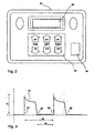
- the controller 42 (also shown in Figure 2 ) includes a receiver 44 capable of receiving, decoding and pre-processing data received from the pneumatic device 28 via the digital communications data link 54. Additionally, controller 42 includes a transmitter 46 capable of pre-processing, encoding and transmitting control data from the controller 42 to the pneumatic device 28 where it is received, manipulated and stored by cpu 36.
- the controller 42 includes a display 56, such as a liquid crystal display or light emitting diode array for displaying either the control data signal or the data signal received from receiver 44, a keypad 58 for the manual entering of data corresponding to the amount of pressure, time and cycle to be transmitted via communications link 54, and a microprocessor 60 for (i) manipulating received data signals or data signals from keypad 58, (ii) displaying data on display 56 and (iii) communicating data with the receiver 44 and transmitter 46.
- a display 56 such as a liquid crystal display or light emitting diode array for displaying either the control data signal or the data signal received from receiver 44
- a keypad 58 for the manual entering of data corresponding to the amount of pressure, time and cycle to be transmitted via communications link 54
- a microprocessor 60 for (i) manipulating received data signals or data signals from keypad 58, (ii) displaying data on display 56 and (iii) communicating data with the receiver 44 and transmitter 46.
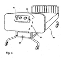
- the controller 48 is, for example as shown in Figure 4 , operably associated with a hospital bed 84, and includes a receiver 52 and a transmitter 50, both of which likewise serve the function as described above, and microprocessor 62 which may likewise include a keypad 64, control knobs 66 for operating a conventional adjustable hospital bed as is known in the art and display 68 capable of producing the necessary control data and transmitting same via communications link 54 to the pneumatic device 28.
- controller 42 may be either manual, manually aided or automated with the use of artificial intelligence software being integrated into the micro processor 60, as is known in the art. Additionally, such intelligence can be integrated into the cpu 36 and/or microprocessor 62.
- the graph 72 shows fluid pressure in the bag 20 with respect to time.
- valve assembly 30 compresses fluid to the bag 20 where the pressure is maintained until predetermined time 82 when the compressed fluid is vented to atmosphere via valve assembly 30.
- the time between the inflation of the preceding cycle and the inflation of the succeeding cycle is given at 76.
- the time between the venting of the preceding cycle and the inflation of the succeeding cycle is given at 78.
- the peak pressure level is shown at 74.
- the medical pumping apparatus 10 may be removably or permanently associated with the hospital bed 84 of the present invention.
- the pneumatic fluid supply device 28 can be installed at a location under the bed on the bed frame, for example, and may be operatively connected to a power source available through the bed 84.
- the digital communications data link 54 is connected to pneumatic fluid supply device 28 and routed through bed 84 to connect to the controller 48 attached to the side of the bed 84.
Landscapes
- Health & Medical Sciences (AREA)
- Epidemiology (AREA)
- Pain & Pain Management (AREA)
- Physical Education & Sports Medicine (AREA)
- Rehabilitation Therapy (AREA)
- Life Sciences & Earth Sciences (AREA)
- Animal Behavior & Ethology (AREA)
- General Health & Medical Sciences (AREA)
- Public Health (AREA)
- Veterinary Medicine (AREA)
- External Artificial Organs (AREA)
- Infusion, Injection, And Reservoir Apparatuses (AREA)
- Invalid Beds And Related Equipment (AREA)
Description
- This invention relates to a remote controllable medical pumping apparatus and more particularly, but not by way of limitation, to a medical apparatus that is capable of controlling from a local site application of compressive pressures to a part of the human body at a remote site.
- Applying pressure to a part of the human body for the purpose of eliciting rapid blood transfer therefrom and subsequently producing Endothelial Derived Relaxing Factor (EDRF) is believed to have therapeutic effects. EDRF (Nitric Oxide) is understood to be a naturally occurring vasodilator which is produced by yield shear stress on the endothelial lining of veins. These shear stresses are readily produced by increasing peak blood flow velocities through a cross section of the vessels. EDRF helps produce hyperaemia by dilating vessels and opening capillaries which also assists in inhibiting the formation of thrombosis.
- It is well known that thromboembolism and pulmonary emboli can result from trauma (such as produced by certain surgeries) or from prolonged venous stasis. These and other factors are known to contribute to the formation of Deep Vein Thrombosis (DVT) in the deep proximal veins of a patient undergoing hip/knee replacement and/or other orthopedic surgery.
- Accordingly, pneumatic compression devices have been utilized on a part of the human body for the purpose of increasing and/or stimulating blood flow in an attempt to help prevent this DVT formation. Such devices have been made to adapt to an arm, hand, foot, calf and thigh and typically include an inflatable bladder or bladders connected to a pneumatic pump capable of delivering pressure within the bladder(s) to cause stimulation. Some devices inflate and deflate in a cyclical fashion, while others utilise a number of bladders which are inflated in a sequential fashion.
- Such devices include an on-site integrally associated control panel interface for the setting, adjustment and programming of the preferred pressure levels and preferred cycle times for the application of pressure to the patient. Such devices required on-site knowledge and skill in order to successfully set, adjust or program its operating parameters in accordance with the on-site monitored patent data. No infrequently, the patient, attendant or other third party inadvertently misadjusts the devices operating parameters. Thus continuous on-site supervision and monitoring of the operating conditions commonly required.
- As representative prior art reference may be made to
EP 0 705 588 A1 , which discloses a medical device of the type described herein for applying a pumping action to the foot but which suffers from the deficiencies of the prior art summarised above. - It is an object to improve medical pumping apparatus.
- It is another object to ease the use of medical pumping apparatus.
- It is an object of the present invention to provide a medical pumping apparatus which has a communications data link and remote controllability for the setting, adjusting and programming of a cycle interval and pressure for the apparatus.
- It is an object of the present invention to provide a medical pumping apparatus which can accumulate data such as patient usage compliance, diagnostic and other specific patient information and then transmit said information over its communications data link.
- It is still another object of the present invention to provide the medical pumping apparatus of the type described as part of a hospital bed.
- Accordingly, the present invention is directed to a remote controllable medical pumping apparatus for controlling from a local site application of compressive pressures to a part of the human body at a remote site. The apparatus includes means disposed at the remote site for applying compressive pressure about the body part in accordance with a predetermined pressure, means disposed at the remote site and operatively associated with the pressure means for sensing at least one of pressure and cycle interval, first transmitting means disposed at the remote site and operatively associated with the sensing means for transmitting a signal in response to the sensed pressure and/or cycle interval, first receiving means disposed at the local site for receiving the transmitted signal, first manipulating means disposed at the local site operably associated with the first receiving means for manipulating the transmitted signal to select or generate pressure signal and/or a cycle interval signal, second transmitting means disposed at the local site and operatively associated with the first manipulating means for transmitting the selected or generated pressure signal and/or cycle interval signal, second receiving means disposed at the remote site for receiving the selected or generated pressure signal, and second manipulating means disposed at the remote site and operatively associated with the second receiving means for manipulating the selected or generated pressure signal and/or cycle interval signal and actuating the pressure means to cause application of pressure to the body part in accordance with the selected or generated pressure signal and/or cycle interval signal.
- Additionally the apparatus includes means disposed at the remote site for sensing patient compliance and wherein the first transmitting means further transmits a signal in response thereto and wherein the first receiving means further receives the patient compliance signal and wherein the first manipulating means further manipulates the transmitted patient compliance signal to either select or generate the pressure signal and/or cycle interval signal. Also, provided are means disposed at the remote site for sensing physiological data and wherein the first transmitting means further transmits a signal in response thereto and wherein the first receiving means further receives the physiological signal and wherein the first manipulating means further manipulates the transmitted physiological signal to either select or generate the pressure signal.
-
-
Figure 1 is a schematic diagram of the remote controllable medical pumping apparatus of the present invention. -
Figure 2 is a remote control of the present invention. -
Figure 3 is a pressure verses time diagram illustrating the inflation cycle and venting cycle normally associated with the sequence of the present invention. -
Figure 4 is a diagram of the medical pumping apparatus integrated into a hospital bed. - Referring now to the drawings,
Figure 1 depicts a remote controllablemedical pumping apparatus 10 of the present invention. Aninflatable bag 20 shaped to conform to and be placed about ahuman foot 24 is secured tofoot 24 by afastener 22. Theinflatable bag 20 can be made of flexible nonpuncturable material such as polyvinyl chloride or polyurethane film which is enveloped and peripherally sealed. Thefastener 22 may be a belt, strap or a VELCRO ™ flap. - A
pneumatic device 28 capable of delivering cyclical pneumatic pressure to thebag 20 is connected thereto via aconduit 26. Theconduit 26 can be fashioned from a plastic hose six to ten feet in length, for example, with a lumen diameter between one quarter and one half inch.Pneumatic device 28 includes avalve assembly 30 operably connected to theconduit 26 for controlling the inflation and venting of thebag 20. A sealedair reservoir 34 operably connects to thevalve assembly 30 and is capable of withstanding as much pressure as is required for the operation of theapparatus 10 and having an adequate safety margin as is readily ascertainable by one skilled in the art. An electrically poweredfluid compressor 32 operably connects to thereservoir 34 for providing compressed air thereto. Also, included is a controller processing unit (cpu) 36 operably connected to thefluid compressor 32 andvalve assembly 30 having non-volatile memory capable of manipulating and storing control data from areceiver 38 and further capable of accumulating specific information, such as accumulated patient compliance data, diagnostic data and other patient physiological related data, and conveying the same to atransmitter 40. Thereceiver 38 is capable of receiving, decoding and pre-processing control data, such as the pressure and cycle time interval, and thetransmitter 40 is capable of pre-processing, encoding and transmitting such data. - As further depicted in
Figure 1 , a digitalcommunications data link 54 is provided via thereceiver 38 andtransmitter 46 and receiver 44 andtransmitter 40 to communicatively connect acontroller 42 with thepneumatic device 28 and associatedcontroller 48.Communications data link 54 includes a digital communications link, such as a hardwired link (directly connected), a wireless infrared link, a wireless radio frequency link, a local area network, or a standard telephone modem link such as is currently employed to enable computers to communicate with each other and their peripherals. The communications protocol ofdata link 54 can be of an industry standard format such as the RS-232 protocol. - The controller 42 (also shown in
Figure 2 ) includes a receiver 44 capable of receiving, decoding and pre-processing data received from thepneumatic device 28 via the digitalcommunications data link 54. Additionally,controller 42 includes atransmitter 46 capable of pre-processing, encoding and transmitting control data from thecontroller 42 to thepneumatic device 28 where it is received, manipulated and stored bycpu 36. Thecontroller 42 includes adisplay 56, such as a liquid crystal display or light emitting diode array for displaying either the control data signal or the data signal received from receiver 44, akeypad 58 for the manual entering of data corresponding to the amount of pressure, time and cycle to be transmitted viacommunications link 54, and amicroprocessor 60 for (i) manipulating received data signals or data signals fromkeypad 58, (ii) displaying data ondisplay 56 and (iii) communicating data with the receiver 44 andtransmitter 46. - The
controller 48 is, for example as shown inFigure 4 , operably associated with ahospital bed 84, and includes areceiver 52 and atransmitter 50, both of which likewise serve the function as described above, andmicroprocessor 62 which may likewise include akeypad 64,control knobs 66 for operating a conventional adjustable hospital bed as is known in the art and display 68 capable of producing the necessary control data and transmitting same viacommunications link 54 to thepneumatic device 28. - It is understood in the invention that the
controller 42 may be either manual, manually aided or automated with the use of artificial intelligence software being integrated into themicro processor 60, as is known in the art. Additionally, such intelligence can be integrated into thecpu 36 and/ormicroprocessor 62. - Referring now to
Figure 3 , the timing diagram for the preferred system is depicted. Thegraph 72 shows fluid pressure in thebag 20 with respect to time. At apredetermined time 80,valve assembly 30 compresses fluid to thebag 20 where the pressure is maintained untilpredetermined time 82 when the compressed fluid is vented to atmosphere viavalve assembly 30. The time between the inflation of the preceding cycle and the inflation of the succeeding cycle is given at 76. The time between the venting of the preceding cycle and the inflation of the succeeding cycle is given at 78. The peak pressure level is shown at 74. These control parameters are set by thecontroller 42 orcontroller 48 and transmitted to the pneumaticfluid supply device 28 by way of thedigital communications link 54. - Referring now to
Figure 4 , themedical pumping apparatus 10 may be removably or permanently associated with thehospital bed 84 of the present invention. The pneumaticfluid supply device 28 can be installed at a location under the bed on the bed frame, for example, and may be operatively connected to a power source available through thebed 84. The digitalcommunications data link 54 is connected to pneumaticfluid supply device 28 and routed throughbed 84 to connect to thecontroller 48 attached to the side of thebed 84. - By so connecting the
controllers device 28, a single communications link is established which permits remote access to thedevice 28 andbed 84, for example, for determining and controlling the same.
Claims (3)
- A medical pumping apparatus for controlling from a local site application of compressive pressures to a part of the human body at a remote site, comprising:a pneumatic device (28) disposed at the remote site for applying compressive pressure about the body part in accordance with a pre-determined pressure, said device including sensing means for sensing said predetermined pressure and pressure cycle interval and a transmitting means (40) operatively associated with the sensing means for transmitting a signal in response to said sensed pressure;first and second control and display means (42, 48) disposed at the local site a remote site respectively, each being independently operable and having a receiver (44, 52) responsive to said transmitted signal to manipulate and display said transmitted signal to enable selection of a signals corresponding to a preferred pressure and pressure cycle interval and a transmitter (46, 50) for transmitting said preferred signals to said device (28) at the remote site, said device (28) further including receiving means (38) for receiving said preferred pressure signal; and manipulating means (30, 36) for manipulating said received preferred pressure signal and actuating said pressure means to cause application of pressure to the body part at pressure cycle intervals in accordance with said generated preferred signal;and a common digital communication link (54) between the first and second control and display means and said device (28) for intercommunication of the signals generated by said sensing means, and transmitting means (40) and said preferred pressure and pressure cycle interval signals.
- The medical pumping apparatus of claim 1, which further includes means disposed at the remote site for sensing patient compliance and wherein said transmitting means (40) further transmits a patient compliance signal in response thereto and wherein each said receiver (44, 52) receives a patient compliance signal and wherein said first and second control and display means (42, 48) further manipulate and display said transmitted patient compliance signal for use in selection of said preferred pressure signal.
- The medical pumping apparatus of claim 1, which further includes means disposed at the remote site for sensing physiological data and wherein said transmitting means (40) further transmits a physiological signal in response thereto and wherein each said receiver (44, 52) receives said physiological signal and wherein said first and second control and display means manipulate and display said transmitted physiological signal for use in selection of said preferred pressure signal.
Applications Claiming Priority (3)
| Application Number | Priority Date | Filing Date | Title |
|---|---|---|---|
| US722296 | 1996-09-30 | ||
| US08/722,296 US6387065B1 (en) | 1996-09-30 | 1996-09-30 | Remote controllable medical pumping apparatus |
| PCT/US1997/017573 WO1998031278A2 (en) | 1996-09-30 | 1997-09-29 | Remote controllable medical pumping apparatus |
Publications (3)
| Publication Number | Publication Date |
|---|---|
| EP0906053A2 EP0906053A2 (en) | 1999-04-07 |
| EP0906053A4 EP0906053A4 (en) | 2007-11-14 |
| EP0906053B1 true EP0906053B1 (en) | 2010-07-28 |
Family
ID=24901256
Family Applications (1)
| Application Number | Title | Priority Date | Filing Date |
|---|---|---|---|
| EP97909903A Expired - Lifetime EP0906053B1 (en) | 1996-09-30 | 1997-09-29 | Remote controllable medical pumping apparatus |
Country Status (4)
| Country | Link |
|---|---|
| US (1) | US6387065B1 (en) |
| EP (1) | EP0906053B1 (en) |
| DE (1) | DE69739944D1 (en) |
| WO (1) | WO1998031278A2 (en) |
Families Citing this family (84)
| Publication number | Priority date | Publication date | Assignee | Title |
|---|---|---|---|---|
| US7922775B2 (en) * | 1999-06-03 | 2011-04-12 | Otto Bock Healthcare Lp | Pulsating pressure chamber and method for fluid management |
| US6726726B2 (en) * | 1999-06-03 | 2004-04-27 | Otto Bock Healthcare Lp | Vacuum apparatus and method for managing residual limb volume in an artificial limb |
| US20040098136A1 (en) | 1999-06-03 | 2004-05-20 | Caspers Carl A. | Socket liner for artificial limb with permanent attachment to socket |
| US7090648B2 (en) * | 2000-09-28 | 2006-08-15 | Non-Invasive Monitoring Systems, Inc. | External addition of pulses to fluid channels of body to release or suppress endothelial mediators and to determine effectiveness of such intervention |
| AU2003233682A1 (en) * | 2002-05-23 | 2003-12-12 | Otto Bock Healthcare Lp | Pulsating pressure chamber and method for enhanced blood flow |
| US7520872B2 (en) | 2002-09-13 | 2009-04-21 | Neogen Technologies, Inc. | Closed wound drainage system |
| US6979324B2 (en) * | 2002-09-13 | 2005-12-27 | Neogen Technologies, Inc. | Closed wound drainage system |
| KR20050122205A (en) | 2003-03-06 | 2005-12-28 | 애퍼런트 코퍼레이션 | Method and apparatus for improving human balance and gait and preventing foot injury |
| WO2004091463A2 (en) * | 2003-04-11 | 2004-10-28 | Hill-Rom Services, Inc. | System for compression therapy |
| USD517695S1 (en) | 2004-02-23 | 2006-03-21 | Tyco Healthcare Group Ip | Compression sleeve |
| US7282038B2 (en) * | 2004-02-23 | 2007-10-16 | Tyco Healthcare Group Lp | Compression apparatus |
| USD506553S1 (en) | 2004-02-23 | 2005-06-21 | Tyco Healthcare Group Lp | Compression sleeve |
| US7871387B2 (en) * | 2004-02-23 | 2011-01-18 | Tyco Healthcare Group Lp | Compression sleeve convertible in length |
| USD523147S1 (en) | 2004-02-23 | 2006-06-13 | Tyco Healthcare Group Lp | Compression sleeve |
| GB0515040D0 (en) * | 2005-07-21 | 2005-08-31 | Bristol Myers Squibb Co | Compression device for the limb |
| GB0515294D0 (en) | 2005-07-26 | 2005-08-31 | Novamedix Distrib Ltd | Limited durability closure means for an inflatable medical garment |
| US8029451B2 (en) | 2005-12-12 | 2011-10-04 | Tyco Healthcare Group Lp | Compression sleeve having air conduits |
| DE202006007460U1 (en) * | 2006-05-09 | 2007-09-13 | Otto Bock Healthcare Products Gmbh | Prosthesis inner shaft system |
| HUE038089T2 (en) * | 2006-12-31 | 2018-09-28 | Linak As | Application such as an electrically adjustable bed or electrically driven patient lift |
| US8083712B2 (en) * | 2007-03-20 | 2011-12-27 | Neogen Technologies, Inc. | Flat-hose assembly for wound drainage system |
| US8128584B2 (en) | 2007-04-09 | 2012-03-06 | Tyco Healthcare Group Lp | Compression device with S-shaped bladder |
| US8162861B2 (en) | 2007-04-09 | 2012-04-24 | Tyco Healthcare Group Lp | Compression device with strategic weld construction |
| US8109892B2 (en) * | 2007-04-09 | 2012-02-07 | Tyco Healthcare Group Lp | Methods of making compression device with improved evaporation |
| US8070699B2 (en) | 2007-04-09 | 2011-12-06 | Tyco Healthcare Group Lp | Method of making compression sleeve with structural support features |
| US8506508B2 (en) | 2007-04-09 | 2013-08-13 | Covidien Lp | Compression device having weld seam moisture transfer |
| US8034007B2 (en) | 2007-04-09 | 2011-10-11 | Tyco Healthcare Group Lp | Compression device with structural support features |
| US8016779B2 (en) | 2007-04-09 | 2011-09-13 | Tyco Healthcare Group Lp | Compression device having cooling capability |
| USD608006S1 (en) | 2007-04-09 | 2010-01-12 | Tyco Healthcare Group Lp | Compression device |
| US8029450B2 (en) | 2007-04-09 | 2011-10-04 | Tyco Healthcare Group Lp | Breathable compression device |
| US8021388B2 (en) | 2007-04-09 | 2011-09-20 | Tyco Healthcare Group Lp | Compression device with improved moisture evaporation |
| US8016778B2 (en) * | 2007-04-09 | 2011-09-13 | Tyco Healthcare Group Lp | Compression device with improved moisture evaporation |
| US9642759B2 (en) * | 2007-04-13 | 2017-05-09 | Stryker Corporation | Patient support with universal energy supply system |
| WO2008132606A2 (en) | 2007-04-27 | 2008-11-06 | Otto Bock Healthcare Ip Gmbh & Co. Kg | Pneumatic connector for prosthetic socket |
| US8114117B2 (en) | 2008-09-30 | 2012-02-14 | Tyco Healthcare Group Lp | Compression device with wear area |
| US8235923B2 (en) | 2008-09-30 | 2012-08-07 | Tyco Healthcare Group Lp | Compression device with removable portion |
| US8257289B2 (en) * | 2010-02-03 | 2012-09-04 | Tyco Healthcare Group Lp | Fitting of compression garment |
| US8652079B2 (en) | 2010-04-02 | 2014-02-18 | Covidien Lp | Compression garment having an extension |
| US20120065561A1 (en) * | 2010-09-03 | 2012-03-15 | Epoch Medical Innovations, Inc. | Device, system, and method for the treatment, prevention and diagnosis of chronic venous insufficiency, deep vein thrombosis, lymphedema and other circulatory conditions |
| US10751221B2 (en) | 2010-09-14 | 2020-08-25 | Kpr U.S., Llc | Compression sleeve with improved position retention |
| US20120083712A1 (en) | 2010-09-30 | 2012-04-05 | Tyco Healthcare Group Lp | Monitoring Compliance Using Venous Refill Detection |
| US8613762B2 (en) | 2010-12-20 | 2013-12-24 | Medical Technology Inc. | Cold therapy apparatus using heat exchanger |
| US20130231596A1 (en) * | 2012-03-02 | 2013-09-05 | David W. Hornbach | Sequential compression therapy compliance monitoring systems & methods |
| US9737454B2 (en) | 2012-03-02 | 2017-08-22 | Hill-Rom Services, Inc. | Sequential compression therapy compliance monitoring systems and methods |
| US9566187B2 (en) | 2012-03-13 | 2017-02-14 | Breg, Inc. | Cold therapy systems and methods |
| US9114055B2 (en) | 2012-03-13 | 2015-08-25 | Cothera Llc | Deep vein thrombosis (“DVT”) and thermal/compression therapy systems, apparatuses and methods |
| US9205021B2 (en) | 2012-06-18 | 2015-12-08 | Covidien Lp | Compression system with vent cooling feature |
| US9402763B2 (en) | 2012-09-12 | 2016-08-02 | Breg, Inc. | Cold therapy apparatus having heat exchanging therapy pad |
| US9872812B2 (en) | 2012-09-28 | 2018-01-23 | Kpr U.S., Llc | Residual pressure control in a compression device |
| US9956113B2 (en) * | 2013-03-12 | 2018-05-01 | The Board Of Trustees Of The Leland Stanford Junior University | Method and system for regulating core body temperature |
| JP6437517B2 (en) | 2013-03-15 | 2018-12-12 | インセラ セラピューティクス,インク. | Vascular treatment apparatus and method |
| USD737327S1 (en) | 2013-06-17 | 2015-08-25 | Covidien Lp | Display screen with a transitional leak detection icon |
| USD737855S1 (en) | 2013-06-17 | 2015-09-01 | Covidien Lp | Display screen with a transitional venous refill detection icon |
| USD774057S1 (en) | 2013-06-17 | 2016-12-13 | Covidien Lp | Display screen with a graphical user interface for compliance monitoring |
| USD737328S1 (en) | 2013-06-17 | 2015-08-25 | Covidien Lp | Display screen with graphical user interface for venous refill detection |
| USD760728S1 (en) * | 2013-06-17 | 2016-07-05 | Covidien Lp | Display screen with graphical user interface for patient use meter reset |
| US20150057585A1 (en) * | 2013-08-20 | 2015-02-26 | Covidien Lp | Compression device having compliance tracking |
| US10226211B2 (en) | 2014-10-11 | 2019-03-12 | Zimmer Dental, Ltd. | System and method for determining user's deep vein thrombosis prevention and diagnosis system utilization compliance |
| CA3001061A1 (en) | 2015-10-09 | 2017-04-13 | Kpr U.S., Llc | Compression garment compliance |
| US10667984B2 (en) | 2015-12-18 | 2020-06-02 | Stryker Corporation | Systems and methods for operating patient therapy devices |
| CN108697423A (en) | 2016-02-16 | 2018-10-23 | 伊瑟拉医疗公司 | The part flow arrangement of suction unit and anchoring |
| EP3207911B1 (en) | 2016-02-18 | 2019-04-03 | Hill-Rom Services, Inc. | Patient support apparatus having an integrated limb compression device |
| US11410771B2 (en) | 2017-06-01 | 2022-08-09 | Stryker Corporation | Patient care devices with open communication |
| US11246775B2 (en) | 2017-12-28 | 2022-02-15 | Stryker Corporation | Patient turning device for a patient support apparatus |
| US11173085B2 (en) | 2017-12-28 | 2021-11-16 | Stryker Corporation | Mattress cover for a mattress providing rotation therapy to a patient |
| USD847864S1 (en) | 2018-01-22 | 2019-05-07 | Insera Therapeutics, Inc. | Pump |
| USD977109S1 (en) | 2018-09-28 | 2023-01-31 | Stryker Corporation | Crib assembly for a patient support |
| USD888962S1 (en) | 2018-09-28 | 2020-06-30 | Stryker Corporation | Cover assembly for a patient support |
| USD888964S1 (en) | 2018-09-28 | 2020-06-30 | Stryker Corporation | Crib assembly for a patient support |
| USD877915S1 (en) | 2018-09-28 | 2020-03-10 | Stryker Corporation | Crib assembly |
| USD879966S1 (en) | 2018-09-28 | 2020-03-31 | Stryker Corporation | Crib assembly |
| USD888963S1 (en) | 2018-09-28 | 2020-06-30 | Stryker Corporation | Cover assembly for a patient support |
| US11559451B2 (en) | 2018-10-31 | 2023-01-24 | Stryker Corporation | Fluid source for supplying fluid to therapy devices |
| USD892159S1 (en) | 2018-10-31 | 2020-08-04 | Stryker Corporation | Display screen with animated graphical user interface |
| USD894957S1 (en) | 2018-10-31 | 2020-09-01 | Stryker Corporation | Display screen or portion thereof with graphical user interface |
| USD893543S1 (en) | 2018-10-31 | 2020-08-18 | Stryker Corporation | Display screen with graphical user interface |
| USD894956S1 (en) | 2018-10-31 | 2020-09-01 | Stryker Corporation | Display screen or portion thereof with graphical user interface |
| USD890914S1 (en) | 2018-10-31 | 2020-07-21 | Stryker Corporation | Pump |
| USD894226S1 (en) | 2018-10-31 | 2020-08-25 | Stryker Corporation | Display screen or portion thereof with graphical user interface |
| USD894223S1 (en) | 2018-10-31 | 2020-08-25 | Stryker Corporation | Display screen with animated graphical user interface |
| US11622883B2 (en) | 2019-01-31 | 2023-04-11 | Flotherm, Inc. | Patient temperature and blood flow management |
| US12403034B2 (en) | 2019-01-31 | 2025-09-02 | Flotherm, Inc. | Sleeve-based body temperature regulation |
| US12502308B2 (en) | 2021-07-01 | 2025-12-23 | Flotherm, Inc. | Flexible heating pads |
| US12220139B2 (en) | 2022-03-20 | 2025-02-11 | Von Vascular, Inc. | System, devices and methods for removing obstructions in body lumens |
| US12262903B2 (en) | 2022-03-20 | 2025-04-01 | Von Vascular, Inc. | System, devices and methods for removing obstructions in body lumens |
Family Cites Families (32)
| Publication number | Priority date | Publication date | Assignee | Title |
|---|---|---|---|---|
| US2880721A (en) | 1958-02-05 | 1959-04-07 | Laurence E Corcoran | Hand or foot carried pulsating massaging device |
| US3859989A (en) | 1973-01-05 | 1975-01-14 | Theodore E Spielberg | Therapeutic cuff |
| US3824992A (en) | 1973-03-16 | 1974-07-23 | Clinical Technology Inc | Pressure garment |
| US3908642A (en) | 1973-10-29 | 1975-09-30 | Pred Vinmont | Means for aerating and applying air pulsations within casts |
| US3993053A (en) | 1974-08-05 | 1976-11-23 | Murray Grossan | Pulsating massage system |
| US3888242A (en) | 1974-08-23 | 1975-06-10 | Stephen W Harris | Compression massage boot |
| US4077402A (en) | 1976-06-25 | 1978-03-07 | Benjamin Jr J Malvern | Apparatus for promoting blood circulation |
| US4091804A (en) | 1976-12-10 | 1978-05-30 | The Kendall Company | Compression sleeve |
| US4206751A (en) | 1978-03-31 | 1980-06-10 | Minnesota Mining And Manufacturing Company | Intermittent compression device |
| US4235437A (en) * | 1978-07-03 | 1980-11-25 | Book Wayne J | Robotic exercise machine and method |
| US4202325A (en) | 1979-01-12 | 1980-05-13 | The Kendall Company | Compression device with improved fastening sleeve |
| US4402312A (en) | 1981-08-21 | 1983-09-06 | The Kendall Company | Compression device |
| US4502470A (en) | 1982-09-16 | 1985-03-05 | Kiser John L | Physiologic device and method of treating the leg extremities |
| US4753226A (en) | 1985-04-01 | 1988-06-28 | Biomedical Engineering Development Center of Sun Yat-Sen University of Medical Science | Combination device for a computerized and enhanced type of external counterpulsation and extra-thoracic cardiac massage apparatus |
| US4702232A (en) | 1985-10-15 | 1987-10-27 | Electro-Biology, Inc. | Method and apparatus for inducing venous-return flow |
| US4809684A (en) | 1985-12-16 | 1989-03-07 | Novamedix Limited | Pressure appliance for the hand for aiding circulation |
| US4846160A (en) | 1985-12-16 | 1989-07-11 | Novamedix Limited | Method of promoting circulation in the hand |
| WO1987006371A1 (en) | 1986-04-10 | 1987-10-22 | Hewlett Packard Limited | Expert system using pattern recognition techniques |
| US4858147A (en) | 1987-06-15 | 1989-08-15 | Unisys Corporation | Special purpose neurocomputer system for solving optimization problems |
| JPS6472727A (en) | 1987-09-14 | 1989-03-17 | Terumo Corp | Automatic hemomanometer |
| US5090417A (en) | 1987-10-22 | 1992-02-25 | Mollan Raymond A B | Medical diagnostic apparatus |
| US5014714A (en) | 1989-07-19 | 1991-05-14 | Spacelabs, Inc. | Method and apparatus for distinguishing between accurate and inaccurate blood pressure measurements in the presence of artifact |
| US5052375A (en) * | 1990-02-21 | 1991-10-01 | John G. Stark | Instrumented orthopedic restraining device and method of use |
| US4993420A (en) | 1990-03-30 | 1991-02-19 | Rutgers University | Method and apparatus for noninvasive monitoring dynamic cardiac performance |
| US5396896A (en) | 1991-05-15 | 1995-03-14 | Chrono Dynamics, Ltd. | Medical pumping apparatus |
| FR2678825B1 (en) * | 1991-07-10 | 1993-11-12 | Michel Fleury | DEVICE FOR PROMOTING BLOOD CIRCULATION IN THE BODY OF A PATIENT. |
| US5584798A (en) * | 1992-11-23 | 1996-12-17 | Novamedix Limited | Medical inflatable cuff appliance |
| US5490820A (en) * | 1993-03-12 | 1996-02-13 | Datascope Investment Corp. | Active compression/decompression cardiac assist/support device and method |
| US5443440A (en) | 1993-06-11 | 1995-08-22 | Ndm Acquisition Corp. | Medical pumping apparatus |
| US5769801A (en) * | 1993-06-11 | 1998-06-23 | Ndm Acquisition Corp. | Medical pumping apparatus |
| US5575762A (en) * | 1994-04-05 | 1996-11-19 | Beiersdorf-Jobst, Inc. | Gradient sequential compression system and method for reducing the occurrence of deep vein thrombosis |
| US5591200A (en) * | 1994-06-17 | 1997-01-07 | World, Inc. | Method and apparatus for applying pressure to a body limb for treating edema |
-
1996
- 1996-09-30 US US08/722,296 patent/US6387065B1/en not_active Expired - Lifetime
-
1997
- 1997-09-29 WO PCT/US1997/017573 patent/WO1998031278A2/en not_active Ceased
- 1997-09-29 DE DE69739944T patent/DE69739944D1/en not_active Expired - Lifetime
- 1997-09-29 EP EP97909903A patent/EP0906053B1/en not_active Expired - Lifetime
Also Published As
| Publication number | Publication date |
|---|---|
| EP0906053A2 (en) | 1999-04-07 |
| US6387065B1 (en) | 2002-05-14 |
| WO1998031278A3 (en) | 1998-11-12 |
| DE69739944D1 (en) | 2010-09-09 |
| WO1998031278A2 (en) | 1998-07-23 |
| EP0906053A4 (en) | 2007-11-14 |
Similar Documents
| Publication | Publication Date | Title |
|---|---|---|
| US6387065B1 (en) | Remote controllable medical pumping apparatus | |
| AU696794B2 (en) | Pneumatic compression device and methods for use in the medical field | |
| US7252646B2 (en) | Universal connecting device that designates an operational mode | |
| EP2314268B1 (en) | Compression treatment system | |
| US5588955A (en) | Method and apparatus for providing therapeutic compression for reducing risk of DVT | |
| US5968073A (en) | Methods and apparatus for applying pressure | |
| US5584798A (en) | Medical inflatable cuff appliance | |
| US4883462A (en) | Blood extraction assist apparatus and method | |
| US6468237B1 (en) | Pneumatic pump, housing and methods for medical purposes | |
| US4077402A (en) | Apparatus for promoting blood circulation | |
| US5496262A (en) | Therapeutic intermittent compression system with inflatable compartments of differing pressure from a single source | |
| US5437610A (en) | Extremity pump apparatus | |
| JPH0838563A (en) | Medical pump device | |
| US20010018564A1 (en) | Medical apparatus for facilitating blood circulation in the lower limbs | |
| EP1119333A1 (en) | Method to augment blood circulation in a limb | |
| US5197461A (en) | Power adjustable orthopedic pillow | |
| AU688742B2 (en) | Blood flow stimulator | |
| CN215425704U (en) | Multifunctional nursing inflatable cushion | |
| WO2022045975A1 (en) | Compression apparatus | |
| CN110897845A (en) | Air wave pressure massage treatment system | |
| CN119405383A (en) | Brachial artery compressor and control method thereof | |
| CN121154386A (en) | Multifunctional leg supporting device and control method thereof | |
| GB2285749A (en) | Apparatus for applying limb compression |
Legal Events
| Date | Code | Title | Description |
|---|---|---|---|
| PUAI | Public reference made under article 153(3) epc to a published international application that has entered the european phase |
Free format text: ORIGINAL CODE: 0009012 |
|
| 17P | Request for examination filed |
Effective date: 19981120 |
|
| AK | Designated contracting states |
Kind code of ref document: A2 Designated state(s): DE FR GB |
|
| A4 | Supplementary search report drawn up and despatched |
Effective date: 20071017 |
|
| 17Q | First examination report despatched |
Effective date: 20080417 |
|
| GRAP | Despatch of communication of intention to grant a patent |
Free format text: ORIGINAL CODE: EPIDOSNIGR1 |
|
| RIC1 | Information provided on ipc code assigned before grant |
Ipc: A61H 23/04 20060101AFI20100126BHEP |
|
| RAP1 | Party data changed (applicant data changed or rights of an application transferred) |
Owner name: NOVAMEDIX DISTRIBUTION LIMITED |
|
| GRAS | Grant fee paid |
Free format text: ORIGINAL CODE: EPIDOSNIGR3 |
|
| GRAA | (expected) grant |
Free format text: ORIGINAL CODE: 0009210 |
|
| RAP1 | Party data changed (applicant data changed or rights of an application transferred) |
Owner name: COVIDIEN AG |
|
| AK | Designated contracting states |
Kind code of ref document: B1 Designated state(s): DE FR GB |
|
| REG | Reference to a national code |
Ref country code: GB Ref legal event code: FG4D |
|
| REF | Corresponds to: |
Ref document number: 69739944 Country of ref document: DE Date of ref document: 20100909 Kind code of ref document: P |
|
| PLBE | No opposition filed within time limit |
Free format text: ORIGINAL CODE: 0009261 |
|
| STAA | Information on the status of an ep patent application or granted ep patent |
Free format text: STATUS: NO OPPOSITION FILED WITHIN TIME LIMIT |
|
| 26N | No opposition filed |
Effective date: 20110429 |
|
| REG | Reference to a national code |
Ref country code: DE Ref legal event code: R097 Ref document number: 69739944 Country of ref document: DE Effective date: 20110429 |
|
| REG | Reference to a national code |
Ref country code: FR Ref legal event code: PLFP Year of fee payment: 20 |
|
| PGFP | Annual fee paid to national office [announced via postgrant information from national office to epo] |
Ref country code: GB Payment date: 20160825 Year of fee payment: 20 Ref country code: DE Payment date: 20160823 Year of fee payment: 20 |
|
| PGFP | Annual fee paid to national office [announced via postgrant information from national office to epo] |
Ref country code: FR Payment date: 20160822 Year of fee payment: 20 |
|
| REG | Reference to a national code |
Ref country code: DE Ref legal event code: R071 Ref document number: 69739944 Country of ref document: DE |
|
| REG | Reference to a national code |
Ref country code: GB Ref legal event code: PE20 Expiry date: 20170928 |
|
| PG25 | Lapsed in a contracting state [announced via postgrant information from national office to epo] |
Ref country code: GB Free format text: LAPSE BECAUSE OF EXPIRATION OF PROTECTION Effective date: 20170928 |
|
| REG | Reference to a national code |
Ref country code: GB Ref legal event code: 732E Free format text: REGISTERED BETWEEN 20180111 AND 20180117 |
|
| REG | Reference to a national code |
Ref country code: FR Ref legal event code: TP Owner name: CARDINAL HEALTH IRELAND UNLIMITED COMPANY, IE Effective date: 20180629 |