EP0905727B1 - Gear recognition switch system - Google Patents
Gear recognition switch system Download PDFInfo
- Publication number
- EP0905727B1 EP0905727B1 EP98307647A EP98307647A EP0905727B1 EP 0905727 B1 EP0905727 B1 EP 0905727B1 EP 98307647 A EP98307647 A EP 98307647A EP 98307647 A EP98307647 A EP 98307647A EP 0905727 B1 EP0905727 B1 EP 0905727B1
- Authority
- EP
- European Patent Office
- Prior art keywords
- actuator
- base wall
- gear recognition
- longitudinal direction
- extending
- Prior art date
- Legal status (The legal status is an assumption and is not a legal conclusion. Google has not performed a legal analysis and makes no representation as to the accuracy of the status listed.)
- Expired - Lifetime
Links
- 230000005540 biological transmission Effects 0.000 claims description 14
- 238000002955 isolation Methods 0.000 claims description 8
- 230000008878 coupling Effects 0.000 claims 3
- 238000010168 coupling process Methods 0.000 claims 3
- 238000005859 coupling reaction Methods 0.000 claims 3
- 230000033001 locomotion Effects 0.000 description 15
- 230000001419 dependent effect Effects 0.000 description 2
- 230000008030 elimination Effects 0.000 description 2
- 238000003379 elimination reaction Methods 0.000 description 2
- 230000002411 adverse Effects 0.000 description 1
- 230000000712 assembly Effects 0.000 description 1
- 238000000429 assembly Methods 0.000 description 1
- 230000004323 axial length Effects 0.000 description 1
- 230000001627 detrimental effect Effects 0.000 description 1
- 238000012986 modification Methods 0.000 description 1
- 230000004048 modification Effects 0.000 description 1
- 238000007747 plating Methods 0.000 description 1
- 238000007788 roughening Methods 0.000 description 1
- 238000010408 sweeping Methods 0.000 description 1
Images



Classifications
-
- F—MECHANICAL ENGINEERING; LIGHTING; HEATING; WEAPONS; BLASTING
- F16—ENGINEERING ELEMENTS AND UNITS; GENERAL MEASURES FOR PRODUCING AND MAINTAINING EFFECTIVE FUNCTIONING OF MACHINES OR INSTALLATIONS; THERMAL INSULATION IN GENERAL
- F16H—GEARING
- F16H59/00—Control inputs to control units of change-speed- or reversing-gearings for conveying rotary motion
- F16H59/02—Selector apparatus
- F16H59/08—Range selector apparatus
- F16H59/10—Range selector apparatus comprising levers
- F16H59/105—Range selector apparatus comprising levers consisting of electrical switches or sensors
-
- H—ELECTRICITY
- H01—ELECTRIC ELEMENTS
- H01H—ELECTRIC SWITCHES; RELAYS; SELECTORS; EMERGENCY PROTECTIVE DEVICES
- H01H15/00—Switches having rectilinearly-movable operating part or parts adapted for actuation in opposite directions, e.g. slide switch
- H01H15/02—Details
- H01H15/06—Movable parts; Contacts mounted thereon
-
- H—ELECTRICITY
- H01—ELECTRIC ELEMENTS
- H01H—ELECTRIC SWITCHES; RELAYS; SELECTORS; EMERGENCY PROTECTIVE DEVICES
- H01H2300/00—Orthogonal indexing scheme relating to electric switches, relays, selectors or emergency protective devices covered by H01H
- H01H2300/02—Application transmission, e.g. for sensing the position of a gear selector or automatic transmission
Definitions
- This invention relates generally to vehicular transmissions and more particularly to apparatus for sensing the position of the manual valve of an automatic transmission which determines the transmissions' mode at any given time.
- Such switch assemblies generally comprise either a rotary movable contact mechanism such as those shown in U.S. Patent Nos. 5,525,768 and 5,440,087, assigned to the assignee of the present invention, or a linear movable contact mechanism such as that shown in U.S. Patent No. 5,231,254, also assigned to the assignee of the present invention.
- the present invention relates to the latter type in which an actuator carrying a set of movable contacts is caused to slide back and forth in dependence upon the longitudinal movement of the manual shaft of the transmission.
- the movable contacts are spring biased into engagement with a stationary contact board having contact segments arranged in a selected pattern so that an on/off output signal is obtained based on the longitudinal position of the manual shaft.
- the actuator is held in place by a housing and some type of cover with clearance provided between the actuator, on the one hand, and the housing and cover on the other hand to permit the actuator to move with the manual shaft.
- erratic and inconsistent voltage output signals have resulted from unintentional motion of the actuator due to the degree of motion available to the actuator.
- Clearances between the actuator and the housing and cover allow the actuator to move in all six directions of motion. Longitudinal, lateral and vertical translation together with pitch, yaw and roll motion alter the movable contact projection onto the stationary contacts thereby intensifying voltage drop irregularities.
- the actuator will move within the associated clearances with sudden impacts between the actuator and the surrounding wall.
- an actuator of a vehicular transmission gear recognition switch system mounts movable contacts which are adapted to slide into and out of engagement with stationary contact segments mounted in an associated housing in dependence upon the movement of the manual shaft of the transmission.
- the actuator comprises integral, flexible members arranged to eliminate clearance between the actuator and the housing in two of three mutually perpendicular directions, the third mutually perpendicular direction being that of the intended motion of the actuator.
- a pair of beams of selected cross sectional area, one on either side of a manual shaft engaging yoke, are formed by respective isolation slots in the base wall of the actuator with a projection formed centrally on each beam.
- the projections are adapted to be received on a platform surface of the housing and the complaint action of the beams eliminates vertical clearance when the beams are loaded upon assembly of the apparatus.
- An additional beam is located in the base wall on one side of the actuator by an isolation slot and is provided with a projection extended laterally outwardly from the side and which cooperates with spaced projections extending laterally outwardly from an opposite side of the actuator and which, when inserted in an opening in the housing, loads the additional beam in the lateral direction thereby eliminating lateral clearance. Elimination of the clearance in the vertical and lateral directions, while allowing longitudinal motion in dependence upon the longitudinal position of the manual shaft of the transmission, results in elimination of contact chatter and enhancement of contact life in the gear recognition switch.
- a gear recognition switch system 10 made in accordance with the invention is shown mounted within a transmission housing and coupled to the manual shaft 12 of the transmission.
- System 10 is attached, as by suitable bolts (not shown) through bores 14a, 14b, to a wall of the transmission housing, removed for the purpose of illustration.
- System 10 provides an electrical output via pins 16 which is dependent upon the position of shaft 12 along the longitudinal axis 12a as will be discussed infra.
- assembly 10 comprises a housing 20, an actuator 22, a movable contact assembly 24, a stationary contact board 26 and a lid 28, in addition to connector 16.
- Housing 20 is formed of suitable moldable, electrically insulative material such as plastic with an open channel 20a between first and second platform surfaces 20b, 20c extending from opposed end walls 20d, 20e respectively.
- the platform surfaces 20b, 20c serve as a sliding seat for the actuator to be discussed below.
- Opposed sidewalls 20f, 20g also form part of the actuator sliding seat and extend between the end walls and above the platform surfaces a selected height.
- Walls 20f, 20g receive contact board 26 thereon and for that purpose are provided with bores 20h.
- Bores 14a, 14b, for mounting the switch system to the transmission housing wall, are provided with suitable bushings 14c, 14d.
- Actuator 22 formed of suitable moldable, electrically insulative material, such as the same material used for housing 20, is provided with a yoke 22a extending downwardly from base wall 22e and mounts movable contact assembly 24 on its upper side.
- Movable contact assembly 24 has a base strip 24a having a plurality of mounting apertures 24b which are received on pegs 22b of actuator 22 which are staked over to lock the movable contact assembly thereon.
- Movable contact assembly 24 has a plurality of electrically conductive, cantilever mounted, contact arms 24c each having a bifurcated contact tip adapted to be biased into engagement with contact board 26 which is mounted over the movable contact assembly. Spacing between the fixed base strip 24a of the movable contact assembly and stationary contact board 26 is determined by castellated, upstanding end walls 22t.
- Contact board 26 formed of suitable moldable, electrically insulative material, has a plurality of spaced, linear contact paths 26a extending between ends 26b, 26c and separated from one another by electrically insulative ribs 26d. Electrically conductive contact segments 26e are disposed at selected longitudinal locations in paths 26a according to a preselected contact pattern. Contact board 26 is provided with a plurality of pegs 26f extending upwardly from its upper side which are received in matching bores 28a of lid 28 and staked thereover to lock the lid to bore 26.
- Actuator 22 is received in housing 20 with yoke 22a extending through channel 20a of the housing and with spaced arms 22c, 22d of the generally U-shaped yoke 22a received in a reduced diameter section 12b of manual shaft 12.
- the width of arms 22c, 22d taken in the longitudinal direction is selected to closely match the axial length of section 12b so that there is minimal clearance in the longitudinal direction.
- Contact board 26 is placed over sidewalls 26f, 26g of actuator 26 and fastened to housing 20 by means of fasteners 30 received through bores 26g of contact board 26 and 20h of housing 20.
- Actuator 22 is adapted to slide back and forth between first and second extremities on the actuator sliding seat formed by platform surfaces 20b, 20c by means of motion imparted through yoke 22a by longitudinal movement of manual shaft 12 along axis 12a.
- Movable contact assembly 24 is connected to an electrical source (not shown) through pins 16 and is adapted to close an electrical circuit with each of the stationary contact segments 26e when in physical engagement therewith. As actuator 22 moves, movable contact 24c slides along respective contact paths 26a in physical engagement therewith so that electrical engagement is effected as the contacts move into engagement with respective stationary contact segments 26e.
- actuator 22 has a base wall 22e having opposed end portions 22f, 22g and opposed side portions 22h, 22i.
- First and second, essentially identical beams 22k having a selected cross sectional area are formed in wall 22e by means of isolation slots 22m and a protrusion 22n is centrally formed between the ends of each beam extending downwardly from the bottom surface of each beam as seen in Fig. 2.
- the cross sectional area of beams 22k is chosen, in cooperation with the length of isolation slots 22m and the material of the actuator, to provide a selected stiffness to the beams, allowing the beams to be deflected in the vertical direction when an upward force is applied to protrusions 22n as will be explained below.
- a protrusion 22o is also formed in the lower surface of wall 22e at each comer of the wall having a height less than that of protrusions 22n and serve both as a stop surface limiting the deflection of beams 22k as well as a sliding surface engageable with platform surfaces 20b, 20c.
- a third beam 22q is formed at side 22i of the actuator by longitudinally extending isolation slot 22r and a laterally outwardly extending protrusion 22s is formed centrally on beam 22q.
- Protruding ribs 22p, extending laterally outwardly, are formed on opposite side 22h and serve as a sliding surface on the inside of wall 20g.
- the distance between sidewalls 20f, 20g of housing 20 is selected to form an interference fit with actuator 22 so that beam 22q will be deflected laterally a selected amount when actuator is placed in housing 20.
- beams 22k When contact board 26 is fastened to housing 20, beams 22k will be deflected vertically and beam 22q will be deflected laterally eliminating clearances between the actuator and the housing in the Z (vertical) direction and the Y(lateral) direction essentially limiting movement to the X (longitudinal) direction.
- the width of arms 22c, 22d (along the longitudinal axis) is selected to be closely received in the reduced diameter portion 12a of manual shaft 12 so that longitudinal movement will be limited essentially to the movement of the manual shaft itself and with yaw about the Z direction, pitch about the Y direction and roll about the X direction essentially eliminated.
- the stiffness of beams 22k, 22q is preferably selected so that the assembly will vibrate at or above 1000 Hertz, suitable for use in an automotive environment, while at the same time staying within an acceptable window of allowable frictional force required to move the actuator along the longitudinal axis by the manual valve. That is, when the shift lever is moved by the driver to select a particular gear position, the gear shift lever rotates and the detent spring snaps a roller into a detent at a fixed position. This detent lever also drives the motion of the manual shaft and if too much force is needed to move the actuator the precise positioning of the mechanism will be adversely affected.
- Fig. 10 shows the output signal of six different electrical switches when subjected to Z-axis vibration of sweeping from approximately 700 to 1000 Hertz at 0.44 octaves per minute using a 20 gram mass at 135°C temperature and a scan rate of 2mm/sec.
- Devices 4-6 were provided with compliant features of beams 22k, 22q and devices 1-3 without such features.
- Devices 1-3 displayed an erratic output due to undesirable actuator motion while devices 4-6 displayed a stable output as a result of the compliant features of beams 22k, 22q made in accordance with the invention.
- the compliant features allow the actuator to absorb vibration and permit the spring contact arms to maintain continuous engagement with the stationary contact board with a controlled contact force independent of the loading of the actuator with the result that the state of the several switches is dependent solely on the position of the manual valve regardless of vibration.
Landscapes
- Engineering & Computer Science (AREA)
- General Engineering & Computer Science (AREA)
- Mechanical Engineering (AREA)
- Control Of Transmission Device (AREA)
- Mechanisms For Operating Contacts (AREA)
Description
- This invention relates generally to vehicular transmissions and more particularly to apparatus for sensing the position of the manual valve of an automatic transmission which determines the transmissions' mode at any given time.
- It is conventional to provide a switch assembly to receive mechanical gear selection inputs from the driver of a vehicle through various linkages and output electrical signals to the transmission electronic control unit indicative of the gear selections. Such switch assemblies generally comprise either a rotary movable contact mechanism such as those shown in U.S. Patent Nos. 5,525,768 and 5,440,087, assigned to the assignee of the present invention, or a linear movable contact mechanism such as that shown in U.S. Patent No. 5,231,254, also assigned to the assignee of the present invention. The present invention relates to the latter type in which an actuator carrying a set of movable contacts is caused to slide back and forth in dependence upon the longitudinal movement of the manual shaft of the transmission. The movable contacts are spring biased into engagement with a stationary contact board having contact segments arranged in a selected pattern so that an on/off output signal is obtained based on the longitudinal position of the manual shaft.
- Typically, the actuator is held in place by a housing and some type of cover with clearance provided between the actuator, on the one hand, and the housing and cover on the other hand to permit the actuator to move with the manual shaft. However, erratic and inconsistent voltage output signals have resulted from unintentional motion of the actuator due to the degree of motion available to the actuator. Clearances between the actuator and the housing and cover allow the actuator to move in all six directions of motion. Longitudinal, lateral and vertical translation together with pitch, yaw and roll motion alter the movable contact projection onto the stationary contacts thereby intensifying voltage drop irregularities. Also, as a result of vibration, the actuator will move within the associated clearances with sudden impacts between the actuator and the surrounding wall. This causes the contact mechanism to jump or bounce resulting in open signals. In addition, a more detrimental mode of failure can result after prolong vibration, that of contact wear. Vibration exacerbates the rubbing action of contacts against each other thereby breaking material, removing plating, if present, and roughening the interface. This action has been found to increase contact resistance from 1 ohm to as much as 700 ohms or more.
- It is an object of the present invention to provide a gear recognition switch system which overcomes the above noted prior art limitations. Another object of the invention is the provision of a linear type gear recognition switch system which is less sensitive to vibration. Yet another object of the invention is the provision of a gear recognition switch system of the type described which is reliable and one which has improved contact life.
- Other objects, advantages and details of the switch apparatus of this invention appear in the following detailed description of the preferred embodiment of the invention.
- Briefly, in accordance with the invention, an actuator of a vehicular transmission gear recognition switch system mounts movable contacts which are adapted to slide into and out of engagement with stationary contact segments mounted in an associated housing in dependence upon the movement of the manual shaft of the transmission. The actuator comprises integral, flexible members arranged to eliminate clearance between the actuator and the housing in two of three mutually perpendicular directions, the third mutually perpendicular direction being that of the intended motion of the actuator. A pair of beams of selected cross sectional area, one on either side of a manual shaft engaging yoke, are formed by respective isolation slots in the base wall of the actuator with a projection formed centrally on each beam. The projections are adapted to be received on a platform surface of the housing and the complaint action of the beams eliminates vertical clearance when the beams are loaded upon assembly of the apparatus. An additional beam is located in the base wall on one side of the actuator by an isolation slot and is provided with a projection extended laterally outwardly from the side and which cooperates with spaced projections extending laterally outwardly from an opposite side of the actuator and which, when inserted in an opening in the housing, loads the additional beam in the lateral direction thereby eliminating lateral clearance. Elimination of the clearance in the vertical and lateral directions, while allowing longitudinal motion in dependence upon the longitudinal position of the manual shaft of the transmission, results in elimination of contact chatter and enhancement of contact life in the gear recognition switch.
-
- Fig. 1 is a perspective view of a gear recognition switch system made in accordance with the invention shown as it appears mounted in a schematically depicted vehicular transmission;
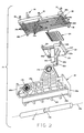
- Fig. 2 is an exploded perspective view of the Fig. 1 system along with a stylized showing of a manual shaft taken from a position slightly below the system;
- Fig. 3 is an exploded perspective view of the Fig. 1 system taken from a position slightly above the system;
- Fig. 4 is a cross sectional view taken through the assembly in a direction perpendicular to the longitudinal axis of the manual shaft receiving opening of the actuator's yoke;
- Fig. 5 is a top plan view of the Figs. 1-4 actuator;
- Fig. 6 is a cross sectional view taken on line 6-6 of Fig. 5;
- Fig. 7 is a bottom plan view of the Fig. 5 actuator;
- Fig. 8 is a perspective view of the actuator from a position above the actuator;
- Fig. 9 is a perspective view of the actuator from a position below the actuator; and
- Fig. 10 is a graph showing the voltage output signal of six different
switches subjected to Z-axis vibration, switches 1, 2 and 3 being prior art
switches and
switches -
- With reference to Fig. 1, a gear
recognition switch system 10 made in accordance with the invention is shown mounted within a transmission housing and coupled to themanual shaft 12 of the transmission.System 10 is attached, as by suitable bolts (not shown) throughbores 14a, 14b, to a wall of the transmission housing, removed for the purpose of illustration.System 10 provides an electrical output viapins 16 which is dependent upon the position ofshaft 12 along thelongitudinal axis 12a as will be discussed infra. As shown in Figs. 2 and 3,assembly 10 comprises ahousing 20, anactuator 22, amovable contact assembly 24, astationary contact board 26 and alid 28, in addition toconnector 16.Housing 20 is formed of suitable moldable, electrically insulative material such as plastic with an open channel 20a between first andsecond platform surfaces opposed end walls platform surfaces sidewalls Walls contact board 26 thereon and for that purpose are provided withbores 20h. Bores 14a, 14b, for mounting the switch system to the transmission housing wall, are provided withsuitable bushings -
Actuator 22, formed of suitable moldable, electrically insulative material, such as the same material used forhousing 20, is provided with ayoke 22a extending downwardly frombase wall 22e and mountsmovable contact assembly 24 on its upper side.Movable contact assembly 24 has abase strip 24a having a plurality of mounting apertures 24b which are received onpegs 22b ofactuator 22 which are staked over to lock the movable contact assembly thereon.Movable contact assembly 24 has a plurality of electrically conductive, cantilever mounted, contactarms 24c each having a bifurcated contact tip adapted to be biased into engagement withcontact board 26 which is mounted over the movable contact assembly. Spacing between thefixed base strip 24a of the movable contact assembly andstationary contact board 26 is determined by castellated, upstanding end walls 22t. -
Contact board 26, formed of suitable moldable, electrically insulative material, has a plurality of spaced, linear contact paths 26a extending betweenends insulative ribs 26d. Electricallyconductive contact segments 26e are disposed at selected longitudinal locations in paths 26a according to a preselected contact pattern.Contact board 26 is provided with a plurality ofpegs 26f extending upwardly from its upper side which are received in matchingbores 28a oflid 28 and staked thereover to lock the lid to bore 26. -
Actuator 22 is received inhousing 20 withyoke 22a extending through channel 20a of the housing and with spacedarms diameter section 12b ofmanual shaft 12. The width ofarms section 12b so that there is minimal clearance in the longitudinal direction.Contact board 26 is placed oversidewalls actuator 26 and fastened tohousing 20 by means offasteners 30 received throughbores 26g ofcontact board housing 20.Actuator 22 is adapted to slide back and forth between first and second extremities on the actuator sliding seat formed byplatform surfaces yoke 22a by longitudinal movement ofmanual shaft 12 alongaxis 12a.Movable contact assembly 24 is connected to an electrical source (not shown) throughpins 16 and is adapted to close an electrical circuit with each of thestationary contact segments 26e when in physical engagement therewith. Asactuator 22 moves,movable contact 24c slides along respective contact paths 26a in physical engagement therewith so that electrical engagement is effected as the contacts move into engagement with respectivestationary contact segments 26e. - With particular reference to Figs. 4-9,
actuator 22 has abase wall 22e having opposedend portions side portions identical beams 22k having a selected cross sectional area are formed inwall 22e by means ofisolation slots 22m and aprotrusion 22n is centrally formed between the ends of each beam extending downwardly from the bottom surface of each beam as seen in Fig. 2. As best seen in Fig. 6, the cross sectional area ofbeams 22k is chosen, in cooperation with the length ofisolation slots 22m and the material of the actuator, to provide a selected stiffness to the beams, allowing the beams to be deflected in the vertical direction when an upward force is applied toprotrusions 22n as will be explained below. A protrusion 22o is also formed in the lower surface ofwall 22e at each comer of the wall having a height less than that ofprotrusions 22n and serve both as a stop surface limiting the deflection ofbeams 22k as well as a sliding surface engageable withplatform surfaces - A third beam 22q is formed at
side 22i of the actuator by longitudinally extendingisolation slot 22r and a laterally outwardly extendingprotrusion 22s is formed centrally on beam 22q. Protrudingribs 22p, extending laterally outwardly, are formed onopposite side 22h and serve as a sliding surface on the inside ofwall 20g. The distance betweensidewalls housing 20 is selected to form an interference fit withactuator 22 so that beam 22q will be deflected laterally a selected amount when actuator is placed inhousing 20. - When
contact board 26 is fastened tohousing 20,beams 22k will be deflected vertically and beam 22q will be deflected laterally eliminating clearances between the actuator and the housing in the Z (vertical) direction and the Y(lateral) direction essentially limiting movement to the X (longitudinal) direction. The width ofarms diameter portion 12a ofmanual shaft 12 so that longitudinal movement will be limited essentially to the movement of the manual shaft itself and with yaw about the Z direction, pitch about the Y direction and roll about the X direction essentially eliminated. - The stiffness of
beams 22k, 22q, determined by the material of the actuator, cross section of the beams and the length of the respective isolation slots, is preferably selected so that the assembly will vibrate at or above 1000 Hertz, suitable for use in an automotive environment, while at the same time staying within an acceptable window of allowable frictional force required to move the actuator along the longitudinal axis by the manual valve. That is, when the shift lever is moved by the driver to select a particular gear position, the gear shift lever rotates and the detent spring snaps a roller into a detent at a fixed position. This detent lever also drives the motion of the manual shaft and if too much force is needed to move the actuator the precise positioning of the mechanism will be adversely affected. - Fig. 10 shows the output signal of six different electrical switches when subjected to Z-axis vibration of sweeping from approximately 700 to 1000 Hertz at 0.44 octaves per minute using a 20 gram mass at 135°C temperature and a scan rate of 2mm/sec. Devices 4-6, were provided with compliant features of
beams 22k, 22q and devices 1-3 without such features. Devices 1-3 displayed an erratic output due to undesirable actuator motion while devices 4-6 displayed a stable output as a result of the compliant features ofbeams 22k, 22q made in accordance with the invention. - The compliant features allow the actuator to absorb vibration and permit the spring contact arms to maintain continuous engagement with the stationary contact board with a controlled contact force independent of the loading of the actuator with the result that the state of the several switches is dependent solely on the position of the manual valve regardless of vibration.
- It should be understood that although the preferred embodiment of the invention has been described in order to illustrate the invention. It is intended that the invention include all such modifications and equivalents falling within the scope of the appended claims.
Claims (10)
- Gear recognition switch apparatus for use in vehicular transmissions comprisinga housing having a bottom wall formed within an elongated channel therein extending along a longitudinal direction, the bottom wall having a platform surface on either side of the channel and having sidewalls extending upwardly from the bottom to form an actuator sliding seat,an actuator received on the actuator sliding seat, the actuator having a base wall and a manual shaft coupling portion extending downwardly through the channel, the actuator formed with flexible portions which form an interference fit in the actuator sliding seat with the actuator slidable along the platform surfaces in the longitudinal direction between first and second extremities,a movable contact assembly disposed on top of the base wall, the movable contact assembly having at least one movable contact arm biased away from the base wall of the actuator, anda stationary contact board received over the movable contact assembly and attached to the housing, the stationary contact board having at least one stationary contact path with an electrically conductive segment selectively positioned in a portion of the contact path, the at least one movable contact arm biased into engagement with the at least one stationary contact path.
- Gear recognition switch apparatus according to claim 1 in which the base wall of the actuator has opposed first and second sides in a lateral direction generally perpendicular to the longitudinal direction and opposed first and second ends in the longitudinal direction in which a flexible portion is formed by a longitudinally extending isolation slot formed in the base wall adjacent the first side thereof forming a flexible beam and a protrusion is formed on the beam extending laterally outwardly.
- Gear recognition switch apparatus according to claim 2 in which the protrusion is formed centrally on the flexible beam.
- Gear recognition switch apparatus according to claim 2 further comprising a pair of spaced apart protrusions on the second side of the actuator extending laterally outwardly.
- Gear recognition switch apparatus according to claim 1 in which the base wall of the actuator has opposed first and second sides in a lateral direction generally perpendicular to the longitudinal direction and opposed first and second ends in the longitudinal direction in which a flexible portion is formed by a pair of vertically deflectable beams formed in the base wall with the manual shaft coupling portion disposed between the pair of beams and a protrusion is formed on each beam extending vertically away from the base wall.
- Gear recognition apparatus according to claim 5 in which each protrusion is formed centrally on the respective deflectable beam.
- Gear recognition apparatus according to claim 5 in which the pair of deflectable beams is formed by first and second longitudinally extending isolation slots through the base wall on either side of each beam.
- Gear recognition apparatus according to claim 1 in which the housing and actuator are formed of moldable plastic material.
- Gear recognition apparatus according to claim 1 in which the manual shaft coupling portion comprises a generally U-shaped yoke having first and second arms having a selected width taken in the longitudinal direction and further comprising a manual shaft having a longitudinal axis and having a reduced diameter portion extending along the longitudinal axis a distance closely matching that of the selected width so that the arms can be received about the reduced diameter portion with minimal clearance in the longitudinal direction.
- Gear recognition apparatus according to claim 5 further comprising a plurality of spaced apart protrusions extending vertically away from the bottom wall to a height less than the height of the protrusions formed on the vertically deflectable beams.
Applications Claiming Priority (2)
| Application Number | Priority Date | Filing Date | Title |
|---|---|---|---|
| US6004497P | 1997-09-25 | 1997-09-25 | |
| US60044P | 1997-09-25 |
Publications (2)
| Publication Number | Publication Date |
|---|---|
| EP0905727A1 EP0905727A1 (en) | 1999-03-31 |
| EP0905727B1 true EP0905727B1 (en) | 2003-02-26 |
Family
ID=22026973
Family Applications (1)
| Application Number | Title | Priority Date | Filing Date |
|---|---|---|---|
| EP98307647A Expired - Lifetime EP0905727B1 (en) | 1997-09-25 | 1998-09-21 | Gear recognition switch system |
Country Status (3)
| Country | Link |
|---|---|
| US (1) | US6518525B1 (en) |
| EP (1) | EP0905727B1 (en) |
| DE (1) | DE69811588T2 (en) |
Families Citing this family (5)
| Publication number | Priority date | Publication date | Assignee | Title |
|---|---|---|---|---|
| EP1672769A3 (en) * | 2004-12-18 | 2009-07-08 | LuK Lamellen und Kupplungsbau Beteiligungs KG | Actuating device for vehicle components |
| JP4527142B2 (en) * | 2007-10-11 | 2010-08-18 | 朝日電装株式会社 | Inhibitor switch and manufacturing method thereof |
| US7939772B2 (en) * | 2007-10-31 | 2011-05-10 | Sensata Technologies, Inc. | Electrical switch system for use with vehicular transmissions |
| JP5551509B2 (en) | 2010-05-13 | 2014-07-16 | デルタ工業株式会社 | Slide switch |
| JP6932074B2 (en) * | 2017-12-13 | 2021-09-08 | 株式会社ヴァレオジャパン | switch |
Family Cites Families (10)
| Publication number | Priority date | Publication date | Assignee | Title |
|---|---|---|---|---|
| US4322588A (en) * | 1980-04-04 | 1982-03-30 | Umc Industries, Inc. | Slide selector switch device |
| JPS57147825A (en) * | 1981-03-06 | 1982-09-11 | Canon Kk | Slide switch mechanism |
| US5015808A (en) | 1989-12-22 | 1991-05-14 | Texas Instruments Incorporated | Normally open pressure switch |
| US5231254A (en) * | 1991-12-11 | 1993-07-27 | Texas Instruments Incorporated | Automobile transmission mode sensing apparatus |
| US5191178A (en) | 1992-01-10 | 1993-03-02 | Texas Instruments Incorporated | Vehicular transmission sensor apparatus responsive to gear selection |
| US5338907A (en) | 1992-01-10 | 1994-08-16 | Texas Instruments Incorporated | Vehicular transmission sensor apparatus responsive to gear selection |
| US5325083A (en) | 1992-05-01 | 1994-06-28 | Chrysler Corporation | Manual valve position sensing system |
| US5440087A (en) | 1994-01-03 | 1995-08-08 | Texas Instruments Incorporated | Switch system for use with motor vehicle transmissions |
| US5525768A (en) | 1995-02-17 | 1996-06-11 | Texas Instruments Incorporated | Switch system for motor vehicle transmissions |
| JP3516555B2 (en) * | 1996-05-29 | 2004-04-05 | ナイルス株式会社 | Sliding switch device |
-
1998
- 1998-02-10 US US09/021,667 patent/US6518525B1/en not_active Expired - Fee Related
- 1998-09-21 DE DE69811588T patent/DE69811588T2/en not_active Expired - Fee Related
- 1998-09-21 EP EP98307647A patent/EP0905727B1/en not_active Expired - Lifetime
Also Published As
| Publication number | Publication date |
|---|---|
| DE69811588D1 (en) | 2003-04-03 |
| DE69811588T2 (en) | 2003-11-20 |
| US6518525B1 (en) | 2003-02-11 |
| EP0905727A1 (en) | 1999-03-31 |
Similar Documents
| Publication | Publication Date | Title |
|---|---|---|
| KR100212107B1 (en) | Lever switches for controlling various electric devices | |
| CA2140225C (en) | Switch assembly | |
| EP0003434A1 (en) | Electrical switch | |
| US4866221A (en) | Remote power mirror switch assembly | |
| CA2198970C (en) | Slide switch with a clicking thruster | |
| CA1184225A (en) | Side actuated miniature dip switch | |
| EP0905727A1 (en) | Gear recognition switch system | |
| KR940005998B1 (en) | Slide selector switch mechanism | |
| US4544811A (en) | Electric switch | |
| CA1160266A (en) | Vehicle turn signal switch actuator | |
| EP1431992A2 (en) | Electrical switch assembly | |
| US5023417A (en) | Switch assembly having a rocker switch connected to a remote actuator | |
| EP1655754B1 (en) | Automotive combination switch | |
| KR20000028573A (en) | Multidirectional input device | |
| CA1174351A (en) | Switch assembly with pivoted actuator | |
| US5068633A (en) | Automatic canceling device for a winker | |
| WO1998009345A1 (en) | Flexible circuit board connector | |
| EP0689215A1 (en) | Self-cleaning switch with pivotable contact | |
| US4313041A (en) | Small switch | |
| US4670630A (en) | Machine insertable DIP switch | |
| US4602137A (en) | Pull-push switch | |
| EP0048552A1 (en) | Electrical switches with a simplified assembly sequence | |
| US4412108A (en) | Electrical switch and actuating mechanism therefor | |
| JP3399170B2 (en) | switch | |
| IE54641B1 (en) | An electro-mechanical switch for a telephone |
Legal Events
| Date | Code | Title | Description |
|---|---|---|---|
| PUAI | Public reference made under article 153(3) epc to a published international application that has entered the european phase |
Free format text: ORIGINAL CODE: 0009012 |
|
| AK | Designated contracting states |
Kind code of ref document: A1 Designated state(s): DE FR GB IT |
|
| AX | Request for extension of the european patent |
Free format text: AL;LT;LV;MK;RO;SI |
|
| 17P | Request for examination filed |
Effective date: 19990902 |
|
| AKX | Designation fees paid |
Free format text: DE FR GB IT |
|
| GRAH | Despatch of communication of intention to grant a patent |
Free format text: ORIGINAL CODE: EPIDOS IGRA |
|
| GRAH | Despatch of communication of intention to grant a patent |
Free format text: ORIGINAL CODE: EPIDOS IGRA |
|
| GRAA | (expected) grant |
Free format text: ORIGINAL CODE: 0009210 |
|
| AK | Designated contracting states |
Designated state(s): DE FR GB IT |
|
| PG25 | Lapsed in a contracting state [announced via postgrant information from national office to epo] |
Ref country code: IT Free format text: LAPSE BECAUSE OF FAILURE TO SUBMIT A TRANSLATION OF THE DESCRIPTION OR TO PAY THE FEE WITHIN THE PRE;WARNING: LAPSES OF ITALIAN PATENTS WITH EFFECTIVE DATE BEFORE 2007 MAY HAVE OCCURRED AT ANY TIME BEFORE 2007. THE CORRECT EFFECTIVE DATE MAY BE DIFFERENT FROM THE ONE RECORDED.SCRIBED TIME-LIMIT Effective date: 20030226 |
|
| REG | Reference to a national code |
Ref country code: GB Ref legal event code: FG4D |
|
| REF | Corresponds to: |
Ref document number: 69811588 Country of ref document: DE Date of ref document: 20030403 Kind code of ref document: P |
|
| ET | Fr: translation filed | ||
| PLBE | No opposition filed within time limit |
Free format text: ORIGINAL CODE: 0009261 |
|
| STAA | Information on the status of an ep patent application or granted ep patent |
Free format text: STATUS: NO OPPOSITION FILED WITHIN TIME LIMIT |
|
| 26N | No opposition filed |
Effective date: 20031127 |
|
| REG | Reference to a national code |
Ref country code: GB Ref legal event code: 732E |
|
| REG | Reference to a national code |
Ref country code: FR Ref legal event code: TP |
|
| PGFP | Annual fee paid to national office [announced via postgrant information from national office to epo] |
Ref country code: FR Payment date: 20080904 Year of fee payment: 11 |
|
| PGFP | Annual fee paid to national office [announced via postgrant information from national office to epo] |
Ref country code: GB Payment date: 20080808 Year of fee payment: 11 |
|
| PGFP | Annual fee paid to national office [announced via postgrant information from national office to epo] |
Ref country code: DE Payment date: 20080930 Year of fee payment: 11 |
|
| GBPC | Gb: european patent ceased through non-payment of renewal fee |
Effective date: 20090921 |
|
| REG | Reference to a national code |
Ref country code: FR Ref legal event code: ST Effective date: 20100531 |
|
| PG25 | Lapsed in a contracting state [announced via postgrant information from national office to epo] |
Ref country code: FR Free format text: LAPSE BECAUSE OF NON-PAYMENT OF DUE FEES Effective date: 20090930 Ref country code: DE Free format text: LAPSE BECAUSE OF NON-PAYMENT OF DUE FEES Effective date: 20100401 |
|
| PG25 | Lapsed in a contracting state [announced via postgrant information from national office to epo] |
Ref country code: GB Free format text: LAPSE BECAUSE OF NON-PAYMENT OF DUE FEES Effective date: 20090921 |