EP0905588A2 - Electronically controlled mechanical timepiece and method of controlling the same - Google Patents
Electronically controlled mechanical timepiece and method of controlling the same Download PDFInfo
- Publication number
- EP0905588A2 EP0905588A2 EP98307937A EP98307937A EP0905588A2 EP 0905588 A2 EP0905588 A2 EP 0905588A2 EP 98307937 A EP98307937 A EP 98307937A EP 98307937 A EP98307937 A EP 98307937A EP 0905588 A2 EP0905588 A2 EP 0905588A2
- Authority
- EP
- European Patent Office
- Prior art keywords
- generator
- brake
- chopper
- signal
- voltage
- Prior art date
- Legal status (The legal status is an assumption and is not a legal conclusion. Google has not performed a legal analysis and makes no representation as to the accuracy of the status listed.)
- Granted
Links
Images


Classifications
-
- G—PHYSICS
- G04—HOROLOGY
- G04C—ELECTROMECHANICAL CLOCKS OR WATCHES
- G04C10/00—Arrangements of electric power supplies in time pieces
-
- G—PHYSICS
- G04—HOROLOGY
- G04C—ELECTROMECHANICAL CLOCKS OR WATCHES
- G04C11/00—Synchronisation of independently-driven clocks
-
- G—PHYSICS
- G04—HOROLOGY
- G04C—ELECTROMECHANICAL CLOCKS OR WATCHES
- G04C3/00—Electromechanical clocks or watches independent of other time-pieces and in which the movement is maintained by electric means
Definitions
- the present invention relates to an electronically controlled mechanical timepiece for correctly driving hands fixed to a train wheel by converting the mechanical energy of a mechanical energy source such as a mainspring or the like into electric energy by a generator and controlling the rotational cycle of the generator by actuating rotation control means by the electric energy.
- the electronically controlled mechanical timepiece disclosed in Japanese Examined Patent Publication No. 7-119812 provides an angular range where the rotating velocity of a rotor is increased by turning off a brake to thereby increase an amount of generated power each time the rotor rotates once, that is, each cycle of a reference signal and an angular range where the rotor is rotated at a low velocity by a brake applied thereto so that the generated power is increased when the rotor is rotated at the high velocity to thereby compensate the drop of the generated power when the brake is applied.
- the electronically controlled mechanical timepiece disclosed in Japanese Unexamined Patent Publication No. 8-101284 increases braking torque and prevents a drop of a generated voltage at the same time by using a number of stages of a boosting circuit for boosting the voltage of the power induced by a generator.
- generated power is dropped at the time in which a brake is applied, it has a limit to suppress a drop of the generated power while increasing braking torque.
- An object of the present invention is to provide an electronically controlled mechanical timepiece capable of increasing the braking torque of a generator while keeping generated power to at least a prescribed level as well as reducing a cost.
- an electronically controlled mechanical timepiece including a mechanical energy source, a generator driven by the mechanical energy source coupled therewith through a train wheel for generating induced power and supplying electric energy from first and second terminals, hands coupled with the train wheel and rotation control means driven by the electric energy for controlling the rotational cycle of the generator characterized by comprising a switch capable of short circuiting the respective terminals of the generator, wherein the rotation control means provides chopper control of the generator by intermittently operating the switch.
- the electronically controlled mechanical timepiece of the present invention drives the hands and the generator by the mainspring and regulates the number of rotation of a rotor, namely, the hands by applying a brake to the generator by the rotation control means.
- the rotation control (brake control) of the generator is carried out by chopper control of the generator by turning ON and OFF the switch capable of short circuiting both the ends of the coil of the generator.
- a short-circuit brake is applied to the generator by the chopper control as well as storing energy in the coil of the generator.
- the switch is turned OFF, the generator is operated and a voltage generated thereby is increased by the energy stored in the coil.
- a choppering frequency for intermittently operating the switch by the rotation control means is at least 5 times as large as the waveform of the voltage generated by the rotor of the generator at a set velocity and it is more preferable that the choppering frequency is 5 to 100 times as large as the waveform of the voltage generated by the rotor of the generator at the set velocity.
- the choppering frequency is at least 5 times as large as the waveform of the generated voltage.
- the choppering frequency is at least 100 times as large as the waveform of the generated voltage, an IC for executing choppering consumes a large amount of power.
- the choppering frequency is 100 times or less the waveform of the generated voltage.
- the choppering frequency is 5 times to 100 times as large as the waveform of the generated voltage, since the changing ratio of torque to the changing ratio of a duty cycle approaches a prescribed level, the control can be easily carried out.
- the choppering frequency may be set to less than 5 times or greater than 100 times depending upon a use and a control method.
- an electronically controlled mechanical timepiece comprises first and second power supply lines for charging the electric energy of the generator to a power supply circuit, wherein the switch is composed of first and second switches interposed between the first and second terminals of the generator and one of the first and second power source lines, respectively and the rotation control means continuously turns ON the switch connected to one of the first and second terminals of the generator as well as intermittently operates the switch connected to the other terminal of the generator.
- the first and second switches are composed of respective transistors.
- the rotation control means comprises a comparator for comparing the waveforms of the voltage generated by the generator with a reference waveform, a comparison circuit for comparing the output from the comparator with a time standard signal and outputting a difference signal, a signal output circuit for outputting a pulse-width varied clock signal based on the difference signal, and a logic circuit for ANDing the clock signal and the output from the comparator and outputting an ANDed signal to the transistors.
- a circuit can be arranged so that it is suitable for a generator of a clock which generates a small amount of power.
- the first switch is composed of a first field effect transistor having a gate connected to the second terminal of the generator and a second field effect transistor connected in series to the first field effect transistor and intermittently operated by the rotation control means
- the second switch is composed of a third field effect transistor having a gate connected to the first terminal of the generator and a fourth field effect transistor connected in series to the third field effect transistor and intermittently operated by the rotation control means and first and second diodes are interposed between the first and second terminals of the generator and the other of the first and second power supply lines, respectively.
- the first switch is composed of a first field effect transistor having a gate connected to the second terminal of the generator and a second field effect transistor connected in series to the first field effect transistor and intermittently operated by the rotation control means
- the second switch is composed of a third field effect transistor having a gate connected to the first terminal of the generator and a fourth field effect transistor connected in series to the third field effect transistor and intermittently operated by the rotation control means
- a boost capacitor is interposed between one of the first and second terminals of the generator and the other of the first and second power supply lines
- a diode is interposed between the other of the first and second terminals and the other of the first and second power supply lines.
- the first terminal of the generator when the first terminal of the generator is set to plus and the second terminal thereof is set to minus (a potential lower than that of the first terminal), the first field effect transistor whose gate is connected to the second terminal is turned ON and the third field effect transistor whose gate is connected to the first terminal is turned OFF.
- the a.c. current generated by the generator flows through the path composed of the first terminal, the first field effect transistor, one of the first and second power supply lines, the power supply circuit, the other of the first and second power supply lines and the second terminal.
- the third field effect transistor whose gate is connected to the first terminal is turned ON and the first field effect transistor whose gate is connected to the second terminal is turned OFF.
- the a.c. current generated by the generator flows through the path composed of the second terminal, the third field effect transistor, one of the first and second power supply lines, the power supply circuit, the other of the first and second power supply lines and the first terminal.
- the second and fourth field effect transistors repeat the ON- and OFF-states in response to the choppering signals input to their gates. Since the second and fourth field effect transistors are connected in series to the first and third field effect transistors, when the first and third field effect transistors are turned ON, a current flows regardless of the turned-ON/OFF states of the second and fourth field effect transistors. However, when the first and third field effect transistors are turned OFF, the current flows when the second and fourth field effect transistors are turned ON in response to a chopper signal.
- both the first and second switches are turned ON to thereby short circuit the respective terminals of the generator.
- the generator can be subjected to a brake control by chopper control so that a drop of generated power when the brake is applied can be compensated by an increase of a generated voltage when the switch is turned OFF, whereby brake torque can be increased while keeping the generated power to at least a prescribed level so that there can be provided an electronically controlled mechanical timepiece having a long operating duration.
- the generator is rectified by the first and third field effect transistors whose gates are connected to the respective terminals, a comparator and the like need not be used, whereby the arrangement is simplified as well as a drop of a charging efficiency due to the power consumed by the comparator can be prevented.
- the field effect transistors are turned ON and OFF making use of the terminal voltage of the generator, the respective field effect transistors can be controlled in synchronism with the polarities of the terminals of the generator, whereby a rectifying efficiency can be improved.
- the power supply circuit and the boost capacitor can be simultaneously charged when the terminal voltage of the terminal to which the capacitor is connected is increased.
- the power supply circuit can be charged with a high voltage obtained by adding the voltage charged to the boost capacitor to the voltage induced by the generator.
- the rotation control means comprises a chopper signal generator for generating at least two types of chopper signals having a different duty ratio and at least the two types of the chopper signals having a different duty ratio are imposed on the switch to thereby provide chopper control of the generator.
- the generator when the switch capable of short circuiting both the terminals of the generator is provided and the generator is chopper controlled by applying the choppering signal to the switch, although a lower chopper frequency and a higher duty ratio can increase drive torque (brake torque) more and a higher chopper frequency increases a charged voltage (generated voltage), they are not so much reduced even if the duty ratio is increased and a point has been found where the charged voltage is increased until the duty ratio is equal to about 0.8 when the chopper frequency is at least 50 Hz.
- the generator is chopper controlled using at least the two chopper signals having a different duty ratio.
- the rotation control means comprises brake control means for switching a brake-ON control for detecting the rotational cycle of the generator and applying a brake to the generator based on the rotational cycle and a brake-OFF control for releasing the brake, the brake control means applies the chopper signals having a different duty ratio on the switch in the brake-ON control and the brake-OFF control and the chopper signal applied in the brake-ON control has a duty ratio larger than that of the chopper signal applied in the brake-OFF control.
- the electronically controlled mechanical timepiece of the present invention drives the hands and the generator by the mainspring and regulates the number of revolutions of the rotor, namely, the hands by applying a brake to the generator by the rotation control means.
- the rotation control of the generator is carried out by imposing a chopper signal on the switch capable of short circuiting both the ends of the coil of the generator and turning ON and OFF the switch, that is, by chopper control of the switch.
- a short-circuit brake is applied to the generator as well as storing energy in the coil of the generator.
- the switch is turned OFF, the generator is operated and a voltage generated thereby is increased by the energy stored in the coil.
- the brake-ON control in which the brake must be applied is carried out by imposing at least the two types of chopper signals having a different duty ratio on the switch, the control torque of the generator can be increased as well as a drop of the generated power can be suppressed by chopper control by imposing a chopper signal having a large duty ratio (in which the switch is turned ON a longer time).
- the brake torque of the generator can be greatly reduced as well as the generated power can be sufficiently obtained by imposing a chopper signal having a duty ratio smaller than that of the above mentioned chopper signal.
- the application of the brake by means of the chopper signal having the large duty ratio and the release thereof by means of the chopper signal having the small duty ratio permit an increase of the brake torque while suppressing a drop of the generated power (power charged to a capacitor and the like), whereby an electronically controlled mechanical timepiece having a long operating duration can be provided.
- the brake-ON control and the brake-OFF control are ordinarily carried out once in each reference cycle of the generator (the cycle during which the rotor rotates once, or the like), only the brake-OFF control may be carried out during a plurality of the reference cycles just after the start of the generator and the like.
- the duty ratio of the respective chopper signals may be suitably set in accordance with the characteristics and the like of the generator to be controlled, it suffices only to use a chopper signal having a large duty ratio of, for example, about 0.7 - 0.95 and a chopper signal having a small duty ratio of about, for example, 0.1 - 0.3.
- the rotation control means comprises a chopper signal generator for generating a chopper signal and brake control means for switching a brake-ON control for detecting the rotational cycle of the generator and applying a brake to the generator based on the rotational cycle and a brake-OFF control for releasing the brake and the brake control means imposes the chopper signal on the switch only in the brake-ON control to thereby chopper control the generator.
- the brake torque of the generator can be increased as well as a drop of generated power can be suppressed by chopper control.
- the rotation control means comprises a chopper signal generator for generating at least two types of chopper signals having a different frequency and at least the two types of the chopper signals having a different frequency are imposed on the switch to thereby chopper control the generator.
- the rotation control means comprises brake control means for switching a brake-ON control for detecting the rotational cycle of the generator and applying a brake to the generator based on the rotational cycle and a brake-OFF control for releasing the brake, wherein the brake control means imposes the chopper signals having a different frequency on the switch in the brake-ON control and the brake-OFF control and the chopper signal imposed in the brake-ON control has a frequency smaller than that of the chopper signal imposed in the brake-OFF control.
- the drive torque (brake torque) is reduced so that a braking effect is decreased as well as the charged voltage (generated voltage) is increased.
- the drive torque is increased and the braking effect is increased as well as the charged voltage is reduced as compared with the case that the frequency is high.
- the charged voltage is increased as compared with a case that only a brake control is simply executed.
- the brake torque of the generator can be increased by imposing the chopper signal having the low frequency as well as a drop of the generated power can be suppressed by the choppering.
- the brake torque of the generator can be greatly reduced by imposing the chopper signal having a frequency which is higher than that of the above mentioned chopper signal on the switch, whereby generated power can be sufficiently obtained.
- the brake torque can be increased while suppressing a drop of the generated power by applying the brake using the chopper signal having the low frequency and releasing the brake using the chopper signal having the high frequency, whereby an electronically controlled mechanical timepiece having a long operating duration can be arranged.
- the frequency of the respective chopper signals may be suitably set in accordance with the characteristics and the like of the generator to be controlled, it suffices only to use a chopper signal having a high frequency of for example, about 500 - 1000 Hz and a chopper signal having a low frequency of, for example, about 10 - 100 Hz.
- the chopper control may be carried out using chopper signals having not only a different frequency but also a different duty ratio.
- a chopper signal having a low frequency and a high duty ratio is used in the brake-ON control and a chopper signal having a high frequency and a low duty ratio is used in the brake-OFF control, the brake control can be effectively carried out.
- the rotation control means comprises a chopper signal generator for generating at least two types of chopper signals having a different frequency and a voltage sensing unit for detecting the voltage of a power supply charged by the generator, wherein the voltage of the power supply detected by the voltage sensing unit is lower than a set value, a chopper signal having a first frequency is imposed on the switch, whereas when the detected voltage of the power supply is higher than the set value, a chopper signal having a second frequency which is lower than the first frequency is imposed on the switch to thereby chopper control the generator.
- the rotation control means comprises brake control means for switching a brake-ON control for detecting the rotational cycle of the generator and applying a brake to the generator based on the rotational cycle and a brake-OFF control for releasing the brake
- the chopper signal generator can generate two types of chopper signals having a different duty ratio at first and second frequencies
- the brake control means imposes chopper signals having one of first and second frequencies which is selected in correspondence to the power supply voltage and a different duty ratio to the switch in the brake-ON control and the brake-OFF control, respectively.
- the chopper signal for executing the brake control of the generator is switched to a chopper signal having a different frequency in accordance with the power supply voltage (voltage charged to the capacitor by the generator, or the like). Accordingly, when the power supply voltage is lower than a set value, a chopper signal which makes the brake torque low and the charged voltage high, that is, which gives priority to charging rather than a braking effect is imposed, whereas when the power supply voltage is higher than the set value, a chopper signal which makes the brake torque high and the charged voltage low, that is, which gives priority to the brake rather than a charging effect is imposed so that a proper brake control can be carried out in accordance with a charged state.
- the rotation control means synchronizes a timing at which the brake-ON control for applying the brake to the generator and the brake-OFF control for releasing the brake are switched with a timing at which the switch is intermittently operated in response to the chopper signal.
- the chopper signal can be also used as a pace measuring pulse.
- the rotation control means comprises rotational cycle sensing means for detecting the rotational cycle of the rotor by means of a rotor rotation sensing signal which is set to one of a low-level and a high-level when the voltage of the rotational waveform of the generator is compared with a reference voltage at a timing of choppering and the voltage of the rotational waveform is equal to or lower than the reference voltage and to the other of the low-level and the high-level when the voltage of the rotational waveform is higher than the reference voltage.
- the rotation control means sets the rotor rotation sensing signal to one of the low-level and the high-level when the voltage of the rotational waveform of the generator which is compared with the reference voltage at the timing of choppering is continuously equal to or lower than the reference voltage by n times, where n is an integer, and sets the rotor rotation sensing signal to the other of the low-level and the high-level when the voltage of the rotational waveform of the generator which is compared with the reference voltage at the timing of choppering is continuously higher than the reference voltage by m times, where m is an integer.
- the n times and the m times are set based on a choppering frequency and a noise frequency superimposed on the rotational waveform of the rotor respectively.
- a chopper pulse is superimposed on the rotational waveform of the rotor of the generator. Therefore, the voltage of the rotational waveform of the rotor is compared with the reference voltage at the timing when the chopper pulse is superimposed (timing at which the choppering is executed) in order to obtain a rectangular wave signal (rotor rotation sensing signal) which corresponds to the rotational cycle of the rotor from the rotational waveform of the rotor.
- Noise such as an external magnetic field for example, a commercial power supply having a frequency of 50/60 Hz
- Noise such as an external magnetic field (for example, a commercial power supply having a frequency of 50/60 Hz) and the like may be superimposed on the rotational waveform of the rotor and there may arise such a case that the rotational waveform of the rotor is deformed by the effect of the noise and a rotor rotation sensing signal cannot be correctly obtained.
- the rotation control means may set the rotor rotation sensing signal to one of the low-level and the high-level when the voltage of the rotational waveform of the generator which is compared with the reference voltage at the timing of choppering is continuously equal to or lower than the reference voltage by x times, where x is an integer, and set the rotor rotation sensing signal to the other of the low-level and the high-level when the rotational waveform of the generator which is compared with the reference voltage at the timing of choppering is higher than the reference voltage by y times (which may be not continuous) and where y is an integer. It is preferable here that the x times and the y times are set based on a choppering frequency and a noise frequency superimposed on the rotational waveform of the rotor.
- the rotation control means may control the rotation of the rotor using a PLL control and may control the rotation of the rotor using an up/down counter.
- the rotation control means may control the rotation of the rotor using any means so long as it preferably compares the rotational waveform of the rotor with the reference waveform from a quartz oscillator and carries out the brake control of the generator so as to reduce the difference therebetween.
- an electronically controlled mechanical timepiece of the present invention including a mechanical energy source, a generator driven by the mechanical energy source coupled therewith through a train wheel for generating induced power and supplying electric energy from a first and second terminals, hands coupled with the train wheel and rotation control means driven by the electric energy for controlling the rotational cycle of the generator
- the method comprises the steps of comparing a reference signal generated based on a signal from a time standard source with a rotation sensing signal output in correspondence to the rotational cycle of the generator, intermittently operating a switch capable of short circuiting the respective terminals of the generator in accordance with an amount of advance of the rotation sensing signal with respect to the reference signal and subjecting the generator to a brake control by choppering.
- the rotation control (brake control) of the generator is carried out by choppering by turning ON and OFF the switch capable of shorting both the ends of the coil of the generator, a drop of generated power which is caused when the brake is applied can be compensated by an increase of the generated voltage when the switch is turned OFF, whereby control torque can be increased while keeping the generated power to at least a prescribed level so that there can be arranged an electronically controlled mechanical timepiece having a long operating duration.
- an electronically controlled mechanical timepiece including a mechanical energy source, a generator driven by the mechanical energy source coupled therewith through a train wheel for generating induced power and supplying electric energy from a first and second terminals, hands coupled with the train wheel and rotation control means driven by the electric energy for controlling the rotational cycle of the generator, the method comprising the steps of inputting a reference signal generated based on a signal from a time standard source and a rotation sensing signal output in correspondence to the rotational cycle of the generator to an up/down counter by setting one of them as an up-count signal and the other of them as a down-count signal, applying a brake to the generator by choppering when the counter value of the up/down counter is equal to a preset value and not applying the brake thereto when the counter value is equal to a value other than the preset value.
- the counter value of the up/down counter is equal to the set value, that is, when the torque of the mechanical energy source such as a mainspring or the like is increased and the rotation of the generator is advanced, a brake is continuously applied by choppering until the difference between respective count values disappears.
- brake torque can be increased while keeping generated power to at least a prescribed level, whereby a rotational velocity can be promptly and correctly regulated so that a control can be executed with excellent responsiveness.
- counting and the comparison of respective count values can be carried out at the same time by means of the up/down counter, the arrangement can be simplified as well as the difference between the respective count values can be simply determined.
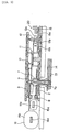
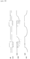
- FIG. 1 is a plan view showing a main portion of an electronically controlled mechanical timepiece according to a first embodiment of the present invention.
- FIG. 2 is a sectional view showing a main portion of FIG. 1.
- FIG. 3 is a sectional view showing a main portion of FIG. 1.
- FIG. 4 is a block diagram showing a function of the first embodiment.
- FIG. 5 is a block diagram showing an arrangement of the fist embodiment.
- FIG. 6 is a circuit diagram showing a chopper charging circuit of the first embodiment.
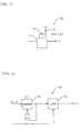
- FIG. 7 is a view showing an example of a waveform shaping circuit of the first embodiment.
- FIG. 8 a view showing another example of the waveform shaping circuit of the first embodiment.
- FIG. 9 is a waveform view in a circuit of the first embodiment.
- FIG. 10 is a view showing processing executed by a comparator of a brake control circuit of the first embodiment.
- FIG. 11 is a flowchart showing a control method of the first embodiment.
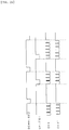
- FIG. 12 is a timing chart in the first embodiment.
- FIG. 13 is a block diagram showing an arrangement of a main portion of an electronically controlled mechanical timepiece of a second embodiment of the present invention.
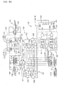
- FIG. 14 is a circuit diagram showing an arrangement of the electronically controlled mechanical timepiece of the second embodiment.
- FIG. 15 is a circuit diagram showing an arrangement of a rectifying circuit of the second embodiment.
- FIG. 16 is a timing chart in an up/down counter of the second embodiment.
- FIG. 17 is a timing chart in a chopper signal generating unit of the second embodiment:
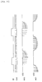
- FIG. 18 is a view showing an output waveform of a generator of the second embodiment.
- FIG. 19 is flowchart showing a control method of the second embodiment.
- FIG. 20 is a timing chart in the second embodiment.
- FIG. 21 is a view showing an output waveform of a generator as a comparative example of the second embodiment.
- FIG. 22 is a circuit diagram showing an arrangement of an electronically controlled mechanical timepiece of a third embodiment.
- FIG. 23 is a view showing an output waveform of a generator of the third embodiment.
- FIG. 24 is a timing chart in the third embodiment.
- FIG. 25 is a circuit diagram showing an arrangement of a electronically controlled mechanical timepiece of a fourth embodiment.
- FIG. 26 is a timing chart in a circuit of the fourth embodiment.
- FIG. 27 is a view showing an output waveform of a generator of the fourth embodiment.
- FIG. 28 is a circuit diagram showing an arrangement of an electronically controlled mechanical timepiece of a fifth embodiment.
- FIG. 29 is a timing chart in a circuit of the fifth embodiment.
- FIG. 30 is a block diagram showing an arrangement of a modification of the present invention.
- FIG. 31 is a circuit diagram showing a modification of the chopper charging circuit of the present invention.
- FIG. 32 is a circuit diagram showing a modification of the chopper charging circuit of the present invention.
- FIG. 33 is a circuit diagram showing a modification of the chopper charging circuit of the present invention.
- FIG. 34 is a circuit diagram showing a modification of the chopper charging circuit of the present invention.
- FIG. 35 is a circuit diagram showing a modification of the chopper charging circuit of the present invention.
- FIG. 36 is a circuit diagram showing a modification of the chopper charging circuit of the present invention.
- FIG. 37 is a view showing a modification of the waveform shaping circuit of the present invention.
- FIG. 38 is a circuit diagram showing a modification of the chopper rectifying circuit of the present invention.
- FIG. 39 is a view showing an arrangement of a modification of a rotor rotation sensing circuit of the present invention.
- FIG. 40 is a view describing an operation of the rotor rotation sensing circuit.
- FIG. 41 is a waveform view showing a rotating waveform of a rotor.
- FIG. 42 is a view describing an operation of another rotor rotation sensing circuit.
- FIG. 43 is a waveform view showing another rotating waveform of a rotor.
- FIG. 44 is a circuit diagram showing a chopper charging circuit in an experimental example of the present invention.
- FIG. 45 is a graph showing the relationship between a choppering frequency and a charged voltage in the experimental example of the present invention.
- FIG. 46 is a graph showing the relationship between a choppering frequency and braking torque in the experimental example of the present invention.
- FIG. 1 is a plan view showing a main portion of an electronically controlled mechanical timepiece according to a first embodiment of the present invention and FIG. 2 and FIG. 3 are sectional views thereof.
- the electronically controlled mechanical timepiece includes a movement barrel 1 composed of a mainspring 1a, a barrel gear 1b, a barrel arbor 1c and a barrel lid 1d.
- the mainspring 1a has an outer end fixed to the barrel gear 1b and an inner end fixed to the barrel arbor 1c.
- the barrel arbor 1c is supported by a main plate 2 and a wheel train receiver 3 and fixed by a ratchet wheel screw 5 so as to be rotated together with the a ratchet wheel 4.
- the ratchet wheel 4 is meshed with a detent 6 so that it is rotated clockwise and is not rotated counterclockwise. Since a method of winding the mainspring 1a by rotating the ratchet wheel 4 clockwise is similar to a winding method using an automatic or manual winding mechanism for a mechanical timepiece, the description of the method is omitted.
- the rotation of the barrel gear 1b is transmitted to a second wheel 7 after its velocity is increased to 7 times the initial velocity thereof and further successively transmitted to a third wheel 8 after its velocity is increased to 6.4 times, to a fourth wheel 9 after its velocity is increased to 9.375 times, to a fifth wheel 10 after its velocity is increased to 3 times, to a sixth wheel 11 after its velocity is increased to 10 times and finally to a rotor 12 after its velocity is increased to 10 times. That is, the rotation of the barrel gear 1b is increased to 126,000 times in total.
- a canon pinion 7a is fixed to the second wheel 7
- a minute hand 13 is fixed to the canon pinion 7a
- a second hand 14 is fixed to the fourth wheel 9, respectively. Therefore, the rotor 12 must be controlled to rotate at 5 rpm in order to rotate the second wheel 7 at 1 rpm and the fourth wheel 9 at 1 rpm. At the time, the barrel gear 1b rotates at 1/7 rpm.
- the electronically controlled mechanical timepiece includes a generator 20 composed of the rotor 12, a stator 15 and a coil block 16.
- the rotor 12 is composed of a rotor magnet 12a, a rotor pinion 12b and a rotor inertia disc 12c.
- the rotor inertia disc 12c is used to reduce a variation in the number of rotations of the rotor 12 with respect to a variation in the drive torque from the movement barrel 1.
- the stator 15 is composed of a stator body 15a and a stator coil 15b wound therearound in an amount of 40000 turns.
- the coil block 16 is composed of a magnetic core 16a and a coil 16b wound therearound in an amount of 110000 turns.
- the stator body 15a and the magnetic core 16a are composed of PC Permalloy or the like.
- the stator coil 15b and the coil 16b are connected in series to each other so that they can output a voltage obtained by adding the voltages generated thereby.
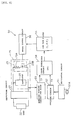
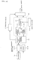
- FIG. 4 is a block diagram showing a function of the embodiment.
- the AC output from the generator 20 is boosted and rectified through a rectifying circuit 21 which executes boosting and rectification, full wave rectification, half wave rectification, transistor rectification and the like.
- a load 22 such as an IC for controlling rotation control means and the like, a quartz oscillator and the like is connected to the rectifying circuit 21.
- FIG. 4 shows respective functional circuits arranged in an IC separately from the load 22 for the convenience of description.
- a braking circuit 23 Connected to the generator 20 is a braking circuit 23 to which a braking resistor 23A and an N-channel or P-channel type transistor 23B functioning as a switch are connected in series.
- a VCO (voltage control oscillator) 25 is composed of the generator 20 and the braking circuit 23.
- a diode may be suitably inserted into the braking circuit 23 in addition to the braking resistor 23A.
- Rotation control means 50 is connected to the VCO 25.
- the rotation control means 50 is composed of an oscillating circuit 51, a dividing circuit 52, a rotation sensing circuit 53 for detecting the rotation of the rotor 12, a phase comparison circuit (PC) 54, a low pass filter (LPF) 55 and a brake control circuit 56.
- PC phase comparison circuit
- LPF low pass filter
- the oscillating circuit 51 outputs an oscillating signal generated by a quartz oscillator 51A and the oscillating signal is divided up to a prescribed frequency by the dividing circuit 52.
- the divided signal is output to the phase comparison circuit 54 as a time standard signal (reference frequency signal) fs of, for example, 100 Hz.
- the reference signal may be created using various types of reference standard oscillation sources in place of the quartz oscillator 51A.
- the rotation sensing circuit 53 receives the output waveform from the VCO 25 at high impedance so that the generator 20 side is not affected thereby, converts the output to a rectangular wave pulse fr and outputs the same to the phase comparison circuit 54.
- the phase comparison circuit 54 compares the phase of the time standard signal fs from the dividing circuit 52 with that of the rectangular wave pulse fr from the rotation sensing circuit 53 and outputs a difference signal as a difference therebetween.
- the difference signal is input to the brake control circuit 56 after its high frequency component is removed by the LPF 55.
- the brake control circuit 56 inputs the control signal from the braking circuit 23 to the VCO 25 based on the above signal, by which a phase synchronous control (PLL control) is realized.
- PLL control phase synchronous control
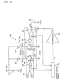
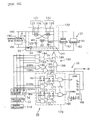
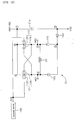
- FIG. 5 shows a more specific arrangement of the embodiment.
- a chopper charging circuit 60 is used as the braking circuit 23 as shown in the figure.
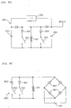
- the chopper charging circuit 60 is composed of two comparators 61, 62 connected to the coils 15b, 16b of the generator 20, a power supply 63 for supplying a comparison reference voltage Vref to the comparators 61, 62, OR circuits 64, 65 for outputting the outputs from the comparators 61, 62 ORed with the clock output (control signal) from the brake control circuit 56, field effect transistors (FETs) 66, 67 which are connected to the coils 15b, 16b and function as switches with the outputs from the OR circuits 64, 65 supplied to the gates thereof and diodes 68, 69 connected to the coils 15b, 16b as well as to a capacitor 21a disposed to the rectifying circuit 21.
- the FET 66, 67 have with parasitic diodes 66A, 67A.
- the + side (first power supply line side) of the capacitor 21a is set to a voltage VDD and the - side thereof (second power supply line side) is set to a VTKN (V/TANK/Negative: the - side of a battery).
- VTKN V/TANK/Negative: the - side of a battery.
- the chopper charging circuit 60 executes chopper boosting by short-circuiting the generator 20 once to the VTKN side by controlling the transistors 66, 67 so that the voltage of the generator 20 is made higher than the voltage VDD when the transistors 66, 67 are released.
- the comparators 61, 62 compare a generated and boosted voltage with the voltage Vref which is arbitrarily set between the VDD and the VTKN.
- the outputs from the comparators 61, 62 are also output to a waveform shaping circuit 70. Accordingly, the rotation sensing circuit 53 is composed of the chopper charging circuit 60 and the waveform shaping circuit 70.
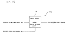
- a monostable multivibrator (one shot type) 71 composed of a capacitor 72 and a resistor 73 as shown in FIG. 7, a type using a counter 74 and a latch 75 as shown in FIG. 8, or the like as the waveform shaping circuit 70.
- the phase comparison circuit 54 is composed of an analog phase comparator, a digital phase comparator and the like and a CMOS type phase comparator using a CMOS IC or the like can be used.
- the phase comparison circuit 54 detects a phase difference between the time standard signal fs of 10 Hz from the dividing circuit 52 and the rectangular wave pulse fr from the waveform shaping circuit 70 and outputs a difference signal.
- the difference signal is input to a charge pump (CP) 80 and converted into a voltage level and a high frequency component is removed therefrom by a loop filter 81 composed of a resistor 82 and a capacitor 83. Therefore, the LPF 55 is composed of the charge pump 80 and the loop filter 81.
- CP charge pump
- the level signal "a" output from the loop filter 81 is input to a comparator 90.
- a triangular signal b is input to the comparator 90 which is obtained by converting the signal from the oscillating circuit 51 through a triangular wave generating circuit 92 which uses a dividing circuit 91 for dividing the signal from the oscillating circuit 51 to 50 Hz - 100 KHz, an integrator and the like.
- the comparator 90 outputs a rectangular wave pulse signal "c" in response to the level signal "a" from the loop filter 81 and the triangular signal "b". Therefore, the brake control circuit 56 is composed of the comparator 90, the dividing circuit 91 and the triangular wave generating circuit 92.
- the rectangular wave pulse signal "c" output from the comparator 90 is input to the chopper charging circuit 60 as a clock signal CLK as described above.
- a.c. waveforms are output from the coils 15b, 15b in accordance with the change of fluxes.
- the waveforms are input to the comparators 61, 62 which compare them with the reference voltage Vref from the power supply 63.
- a timing of polarity for turning ON the transistors 66, 67 is detected by the comparison executed by the comparators 61, 62.
- boosting and charging to the capacitor 21a and a chopper braking operation of the generator 20 can be carried out only by inputting the clock signal CLK to the gates of the transistors 66, 67.
- the transistors 66, 67 are simultaneously turned ON and short circuited, whereas when the clock signal is equal to a low-level, the capacitor 21a is charged through one of the parasitic diodes 66A, 67A and one of the diodes 68, 69.
- the capacitor 21a when a terminal AG1 is made to a positive level, the capacitor 21a is charged through a path from the parasitic diode 67A to the diode 68 through the coils 15b, 16b, whereas when a terminal AG2 is made to a positive level, the capacitor 21a is charged through a path from the parasitic diode 66A to the diode 69 through the coils 15b, 16b.
- the embodiment improves the charging efficiency by regulating the timing of the transistors 66, 67 without simultaneously turning them ON and OFF.
- the comparator 61 when the terminal AG1 is made to + when viewed from the VTKN and exceeds the voltage Vref, the comparator 61 outputs a high-level signal so that the OR circuit 65 continuously outputs a high-level signal regardless of the clock signal CLK, whereby the transistor 67 is turned ON by a voltage applied to the gate thereof.
- the comparator 61 connected to the terminal AG2 outputs a low-level signal due to AG2 ⁇ voltage Vref
- the OR circuit 64 outputs a signal which is synchronized with the clock signal
- the transistor 66 repeats an ON/OFF operation and the terminal AG1 is chopper boosted.
- the charging path at the time is set to AG1 - diode 68 - capacitor 21a - VTKN - transistor 67 (from source to drain) - AG2 and the parasitic diode 67A is removed from the path, when the transistor 66 is turned on once and then turned off, whereby a voltage drop is reduced and the charging efficiency is improved.
- the level of the voltage Vref a generated voltage level which permits the voltage generated by the generator 20 to be chopper boosted and charged to the capacitor 21a.
- the voltage Vref is set to a level exceeding the VTKN by several hundred millivolts.
- a power generating efficiency is lowered accordingly because a period until the comparators 61, 62 are put into operation is increased and the two diodes are connected in series in a charging path during the period, whereby the power generating efficiency is lowered.
- the generator 20 When the transistor 66 is turned ON, the generator 20 is short circuited because the transistor 67 is also turned ON at the time. As a result, a short-circuit brake is applied to the generator 20 and an amount of generated power is reduced accordingly.
- the voltage of the generator 20 can be boosted to a level higher than VDD by short circuiting the generator 20 to the VTKN side when the transistor 66 is released. Therefore, when a choppering cycle for tuning ON and OFF the transistors is set higher than a prescribed cycle, a drop of a generated power can be compensated when the short-circuit brake is applied so that brake torque can be increased while maintaining generated power to a level higher than a prescribed level.
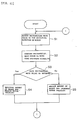
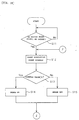
- step 1 The outputs from the comparators 61, 62 of the chopper charging circuit 60 are input to the waveform shaping circuit 70 and converted into the rectangular wave pulse fr. That is, the rotation sensing circuit 53 composed of the chopper charging circuit 60 and the waveform shaping circuit 70 detects the rotation of the rotor 12 and outputs it as the rectangular wave pulse fr (step 1, hereinafter, step is abbreviated as "S").
- the monostable multivibrator 71 shown in FIG. 7 executes waveform shaping by detecting only one polarity (the output from the comparator 62). More specifically, the monostable multivibrator 71 is trigged in response to the rising-up edge of output from the comparator 62 and outputs a pulse having a length set by a CR. Since the CR has a time constant set about 1.5 times the one cycle of the clock signal CLK, the rising-up edge of the next output of the comparator 62 is input within the pulse time set by the CR to thereby trigger the monostable multivibrator 71.
- the monostable multivibrator 71 continuously outputs a high-level signal until the rising-up edge of the output from the comparator 62 is not generated within the time 1.5T set by the CR so that the rectangular wave pulse fr corresponding to the output signal of the generator 20 is output.
- a waveform shaping circuit 70 shown in FIG. 8 also executes waveform shaping by detecting only one polarity (the output of one of the comparators 61, 62). More specifically, the waveform shaping circuit 70 is composed of a counter 74 for counting the clock signal for only a time 2T and clearing it and latch means 75 for applying a latch in response to the output from the counter 74. The counter 74 and the latch means 75 are set so that they are cleared in response the output from any of the comparators 61, 62. For example, the output is generated from the comparator 62, the latch means 75 and the counter 74 are cleared and the output fr outputs a low-level signal as shown in FIG. 9. When the output is not generated from the comparator 62, the output fr is latched to a high-level by the counter 74.
- the respective waveform shaping circuits 70 shown in FIGS. 7, 8 convert the output from the comparator 62 into the rectangular wave pulse by causing a delay to it. This is executed to prevent the occurrence of incorrect pulse by the time set to the CR or the time set to the counter because the output from the comparator 62 at the start of the system, and the like is not always obtained as a signal synchronized with the cycle of the clock signal and made to an output with lack of pulse and when the output is converted into the rectangular wave pulse as it is, there is caused the incorrect pulses.
- the times set to the CR and the counter may be set to about 1.5 - 5T in accordance with the degree of the lack of pulse. The delay does not have any affect in control.
- the rectangular wave pulse fr shaped as described above is compared with the time standard signal fs of the dividing circuit 52 by the phase comparison circuit 54 (S2) and the difference signal thereof is converted into the level signal "a" through the charge pump 80 and the loop filter 81.
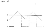
- the comparator 90 outputs a rectangular wave pulse signal "c" in response to the level signal a and the triangular signal “b” from the triangular wave generating circuit 92 as shown in FIG. 10.
- the level signal "a” is set such that when the rectangular wave pulse fr based on the rotation of the rotor 12 advances with respect to the time standard signal fs, it is made lower than a standard level, whereas when it is delayed with respect thereto, it is made higher than the standard level.
- the rectangular wave pulse fr advances with respect to the time standard signal fs (S3)
- the rectangular wave pulse signal "c" is in a high-level state for a longer time to thereby increase a short-circuit brake period in the respective chopper cycles in the chopper charging circuit 60 so that an amount of brake is increased and the velocity of the rotor 12 of the generator 20 is reduced (S4).
- the rectangular wave pulse fr is delayed with respect to the time standard signal fs
- the rectangular wave pulse signal "c" is in a low-level state for a longer time to thereby decrease the short-circuit brake period in the respective chopper cycles in the chopper charging circuit 60 so that the amount of brake is decreased and the velocity of the rotor 12 of the generator 20 is increased (S5).
- the rectangular wave pulse fr is controlled by the repetition of the above brake control so that it corresponds to the time standard signal fs.
- the relationship between the time standard signal fs and the rectangular wave pulse fr from the waveform shaping circuit 70 shown in FIGS. 4, 5 and the signal "c" output from the comparator 90 can be represented by a timing chart as shown in FIG. 12. That is, the output signal "c" from the comparator 90 is arranged such that the short-circuit brake period is increased to thereby increase the amount of brake or decreased to thereby reduce the amount of brake in accordance with the phase difference between the time standard signal fs and the rectangular wave pulse fr. That is, in the comparison of the cycles T1, T2 and T3 of the time standard signal fs shown in FIG.
- the output signal c from the comparator 90 in the next cycle (cycle T3) following the previous cycle T2 is set to decrease the short-circuit brake period to thereby reduce the amount of brake as compared with the case that the phase difference between the falling edge of the rectangular wave pulse fr is compared with that of the subsequent reference frequency signal fs in the cycle T1 (that is, as compared with the cycle T2).
- the output signal c is set the same waveform over the one cycle of the time standard signal fs, that is, a waveform having the same short-circuit brake period.
- the brake period is set to a high-level so that a brake is applied when the output signal c is at the high-level.
- the embodiment can obtain the following effects.
- the rotation of the generator 20 can be controlled by the PLL control.
- a brake level can be set in the brake circuit 23 by comparing the waveforms of generated power at respective cycles, when the generator 20 is pulled in a lock range once, it can be stably controlled with prompt responsiveness unless the waveforms of generated power greatly vary at a moment.
- the brake circuit 23 is composed of the chopper charging circuit 60 and the brake control is realized using chopper control, control torque can be increased while keeping a generated power to at least a prescribed level. As a result, the brake control can be effectively executed while maintaining the stability of the system.
- the chopper charging circuit 60 Since the chopper charging circuit 60 is used, not only the brake control but also the charging to the capacitor 21a through the rectifying circuit 21 (power generation processing) and the detection of the rotation of the rotor 12 of the generator 20 can be realized by the chopper charging circuit 60. Therefore, a circuit arrangement can be simplified, a cost can be reduced by decreasing the number of parts and a manufacturing efficiency can be improved as compared with a case that these respective functions are realized by individual circuits.
- the chopper charging circuit 60 controls the timing at which the respective transistors 66, 67 are turned ON and OFF and turns ON and OFF one of the transistors 66, 67 in a state that the other thereof is continuously turned ON, a voltage drop in the charging path can be reduced and a power generating efficiency can be improved. This is very effective because the power generating efficiency of the generator 20 can be improved by it when the generator 20 which is small in size must be used as required in the electronically controlled mechanical timepiece.
- the waveform shaping circuit 70 Since the waveform shaping circuit 70 is provided, even if the output waveform from the VCO 25 is changed by the change of the circuit arrangement of the chopper charging circuit 60 and the like, the different portion of the output waveform can be absorbed by the waveform shaping circuit 70. As a result, even if the circuit arrangement of the chopper charging circuit 60 is different, the rotation control means 50 can be commonly used so that a part cost can be reduced thereby.
- FIG. 13 shows a block diagram showing an electronically controlled mechanical timepiece of the second embodiment.
- the electronically controlled mechanical timepiece includes a mainspring 1a as a mechanical energy source, a velocity increasing train wheel (wheels 7 - 11) for transmitting the torque of the mainspring 1a to a generator 20 and hands (a minute hand 13 and a second hand 14) coupled with the velocity increasing train wheel for displaying a time.
- the generator 20 is driven by the mainspring 1a through the velocity increasing train wheel and supplies electric energy by inducing power.
- the a.c. output from the generator 20 is boosted and rectified through a rectifying circuit 21 which executes boosting and rectification, full wave rectification, half wave rectification, transistor rectification and the like and charged to a power supply circuit 21a composed of a capacitor and the like.
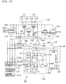
- the generator 20 is provided with a brake circuit 120 including a rectifying circuit 35 as shown in FIG. 14. More specifically, the brake circuit 120 is composed of first and second switches 121, 122 for applying a short circuit brake by short circuiting a first terminal MG1 and a second terminal MG2 which are the output terminals of the generator 20.
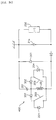
- the first switch 121 is composed of a first P-channel field effect transistor (FET) 126 having a gate connected to the second terminal MG2 and a second field effect transistor 127 having a gate to which the chopper signal (chopper pulse) CH3 from a chopper signal generator 180 to be described later is input, the first field effect transistor 126 being connected in series to the second field effect transistor 127 as shown in FIG. 15.
- FET field effect transistor
- the second switch 122 is composed of a third P-channel field effect transistor (FET) 128 having a gate connected to the first terminal MG1 and a fourth field effect transistor 129 having a gate to which the chopper signal (chopper pulse) CH3 from the chopper signal generator 180 is input, the third field effect transistor 128 being connected in series to the fourth field effect transistor 129.
- FET field effect transistor
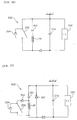
- a voltage doubler rectifying circuit (simplified synchronously boosting chopper rectifying circuit) 35 is composed of a boost capacitor 123, diodes 124, 125, a first switch 121 and a second switch 122 which are connected to the generator 20. Any type of one-direction devices for flowing a current in one direction may be used as the diodes 124, 125.
- the voltage generated by the generator 20 is small in an electronically controlled mechanical timepiece, it is preferable to use a Schottky barrier diode having a small voltage drop Vf as the diode 125. Further, it is preferable to use a silicon diode having a small inverse leak voltage as the diode 124.
- the brake circuit 120 is controlled by rotation control means 50 which is driven by the power supplied from the power supply circuit (capacitor) 21a.
- the rotation control means 50 is composed of an oscillating circuit 51, a rotation sensing circuit 53 for a rotor and a control circuit 56 for a brake.
- the oscillating circuit 51 outputs an oscillating signal (32768 Hz) using a quartz oscillator 51A as a time standard source and the oscillating signal is divided up to a prescribed frequency by a dividing circuit 52 composed of a 12-stage flip-flop.
- the twelve stage output Q12 from the dividing circuit 52 is output as a reference signal of 8 Hz.
- the rotation sensing circuit 53 is composed of a waveform shaping circuit 161 connected to the generator 20 and a mono-multi vibrator 162.
- the waveform shaping circuit 161 is composed of an amplifier and a comparator and converts a sine wave into a rectangular wave.
- the mono-multi vibrator 162 functions as a band-pass filter for passing a pulse having a certain frequency or less and outputs a rotation sensing signal FG1 from which noise is removed.
- the control circuit 56 includes an up/down counter 160 as a brake control circuit, a synchronous circuit 170 and the chopper signal generator 180.
- the rotation sensing signal FG1 from the rotation sensing circuit 53 and the reference signal fs from the dividing circuit 52 are input to the up-count input terminal and the down-count input terminal of the up/down counter 160 through the synchronous circuit 170.
- the synchronous circuit 170 is composed of four flip-flops 171, AND gates 172 and NAND gates 173 and synchronizes the rotation sensing signal FG1 with the reference signal fs (8 Hz) making use of the output Q5 (1024 Hz) from the fifth stage of the dividing circuit 52 and the output Q6 (512 Hz) from the sixth stage thereof as well as makes adjustment to prevent the respective signal pulses from being output in a superimposed state.
- the up/down counter 160 is composed of a 4-bit counter.
- a signal based on the rotation sensing signal FG1 is input to the up-count input terminal of the up/down counter 160 from the synchronous circuit 170 and a signal based on the reference signal fs is input to the down-count input terminal thereof from the synchronous circuit 170.
- the reference signal fs and the rotation sensing signal FG1 are counted and the difference therebetween is calculated at the same time.
- the up/down counter 160 includes four data input terminals (preset terminals) A - D and a high-level signal is input to the terminals A - C so that the initial value (preset value) of the up/down counter 160 is set to a counter value 7.
- An initializing circuit 190 is connected to the LOAD input terminal of the up/down counter 160 for outputting a system reset signal SR in accordance with the voltage of the power supply circuit 21a.
- the initializing circuit 190 outputs a high-level signal until the charged voltage of the power supply circuit 21a is equal to a prescribed voltage and outputs a low-level signal when the charged voltage is equal to at least the prescribed voltage.
- the up/down counter 160 Since the up/down counter 160 does not receive an up-down input until the LOAD input terminal is made to a low-level, that is, until the system reset signal SR is output, the counter value of the up/down counter 160 is kept to "7".
- the up/down counter 160 has 4-bit output terminals QA - QD. Therefore, the fourth bit output terminal QD outputs a low-level signal when the counter value is 7 or less, whereas it outputs a high-level signal when the counter value is 8 or more.
- the output terminal QD is connected to the chopper signal generator 180.
- the chopper signal generator 180 includes a first chopper signal generation means 181 which is composed of three AND gates 182 - 184 and outputs a first chopper signal CH1 making use of the outputs Q5 - Q8 of the dividing circuit 52, a second chopper signal generation means 185 which is composed of two OR gates 186, 187 and outputs a second chopper signal CH2 making use of the outputs Q5 - Q8 of the dividing circuit 52, an AND gate 188 to which the output QD of the up/down counter 160 and the output CH2 of the second chopper signal generation means 185 are input and a NOR gate 189 to which the output of the AND gate 188 and the output CH1 of the first chopper signal generation means 181 are input.
- a first chopper signal generation means 181 which is composed of three AND gates 182 - 184 and outputs a first chopper signal CH1 making use of the outputs Q5 - Q8 of the dividing circuit 52
- the output CH3 from the NOR gate 189 of the chopper signal generator 180 is input to the gates of second and fourth field effect transistors 127, 129. Therefore, when a low-level signal is output from the output CH3, the transistors 127, 129 are kept in a turned-ON state so that the generator 20 is short circuited and a brake is applied thereto.
- the generator 20 can be chopper controlled by the chopper signal from the output CH3.
- the output CH1 is output from the first chopper signal generation means 181 and the output CH2 is output from the second chopper signal generation means 185 making use of the output Q5 - Q8 of the dividing circuit 52 as shown in FIG. 17.
- the output CH3 from the NOR gate 189 is made to a chopper signal obtained by inverting the output CH1, that is, a chopper signal having a small duty ratio (ratio at which the transistors 127, 129 are turned ON) at which a high-level signal (brake-OFF time) is long and a low-level signal (brake-ON time) is short. Therefore, the brake-ON time is reduced at a reference cycle so that almost no brake is applied to the generator 20, that is, a brake-OFF control giving priority to power generation is carried out (S13, S15).
- the output CH3 from the NOR gate 189 is made to a chopper signal obtained by inverting the output CH2, that is, a chopper signal having a large duty ratio at which a low-level signal (brake-ON time) is long and a high-level signal (brake-OFF time) is short. Therefore, the brake-ON time is increased at the reference cycle and a brake-ON control is carried out to the generator 20. However, since the brake is turned OFF at a prescribed cycle, chopper control is carried out so that brake torque can be improved while suppressing the drop of generated power (S13, S14).
- the voltage doubler rectifying circuit (simplified synchronously boosting chopper rectifying circuit) 35 charges the electric charge generated by the generator 20 to the power supply circuit 21a as described below. That is, when the polarity of the first terminal MG1 is "+” and the polarity of the second terminal MG2 is "-", the first field effect transistor (FET) 126 is turned ON and the third field effect transistor (FET) 128 is turned OFF. As a result, the electric charge of the voltage induced by the generator 20 is charged to the capacitor 123 of, for example, 0.1 mF through the circuit "(4) ⁇ (3) ⁇ (7) ⁇ (4)" shown in FIG. 15 as well as to the power supply circuit (capacitor) 21a of, for example, 10 mF through the circuit "(4) ⁇ (5) ⁇ (6) ⁇ (1) ⁇ (2) ⁇ (3) ⁇ (7) ⁇ (2)".
- an up-counter value may be further input after the counter value is set to "8" by the up-count signal (UP).
- the counter value is set to "9” and the brake-ON control of the chopper signal is carried out by the chopper signal CH3 to keep the output QD to the high-level.
- the rotational velocity of the generator 20 is lowered by the application of a brake thereto.
- the rotational velocity of the generator 20 approaches a set rotational velocity and the operation shifts to a lock state in which the up-count signal (UP) and the down-count signal (DOWN) are alternately input and the counter value repeats "8" and "7".
- the brake is repeatedly turned ON and OFF in accordance with the counter value. That is, the chopper control is carried out by the application of the chopper signal having the large duty ratio and the chopper signal having the small duty ratio to the transistors 127, 129 in the one reference cycle in which the rotor rotates once.
- the brake-ON control is carried out in response to the chopper signal having the large duty ratio
- the brake-OFF control is carried out in response to the chopper signal having the small duty ratio. That is, the brake-ON control and the brake-OFF control are switched by the up/down counter 160 as the brake control means.
- an a.c. waveform corresponding to the change of a flux is output from the terminals MG1, MG2 of the generator 20.
- the chopper signals CH3 having a constant frequency and a different duty ratio are suitably applied to the transistors 127, 129 in accordance with the signal from the output terminal QD.
- the output terminal QD outputs the high-level signal, that is, when the brake-ON control is carried out, the short-circuit brake time is increased in each chopper cycle to thereby increase an amount of brake so that the rotational velocity of the generator 20 is reduced.
- the power can be chopper boosted by outputting the energy accumulated in the short-circuit brake when the transistors 127, 129 are turned OFF by the chopper signal. Accordingly, the reduction of the generated power in the short-circuit brake can be compensated so that the brake torque can be increased while suppressing a drop of the generated power.
- the short-circuit brake time is decreased in each chopper cycle to thereby reduce an amount of brake so that the rotational velocity of the generator 20 is increased. Since the power can be chopper boosted when the transistors 127, 129 are switched from the OFF state to the ON state also at this time, the generated power can be improved even if it is compared with a case that a control is carried out without applying a brake at all.
- the a.c. output from the generator 20 is boosted and rectified by the voltage doubler rectifying circuit 35 and charged to the power supply circuit (capacitor) 21a and the rotation control means 50 is driven by the power supply circuit 21a.
- both the output QD of the up/down counter 160 and the chopper signal CH3 make use of the outputs Q5 - Q8, Q12 of the dividing circuit 52, that is, since the frequency of the chopper signal CH3 is equal to an integral multiple of the frequency of the output QD, the change of the output level of the output QD, that is, the timing at which the brake-ON control and the brake-OFF control are switched and the chopper signal CH3 are generated in synchronism with each other.
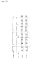
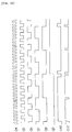
- FIG. 20 shows the relationship between the down-count signal (DOWN) of 8 Hz, the up-count signal (UP) of 8 Hz and the chopper signal (CH3) shown in FIG. 16 - FIG. 18 in a timing chart.
- the chopper signal (CH3) is synchronized with the down-count signal (DOWN) and the up-count signal (UP).
- the chopper signal (CH3) may not be synchronized with the down-count signal (DOWN) and the up-count signal (UP) and may have a waveform which starts from a high-level of the chopper signal (CH3') in a certain cycle of the respective signals (DOWN, UP) or from a low-level thereof in a certain cycle thereof.
- the brake period is set to a low-level so that a brake is applied when the chopper signal CH3 is at the low-level.
- the choppering signal need not be synchronized with a velocity which is set to control the rotation of the rotor 12, that is, with a velocity which permits the display of a correct time so long as the rotor 12 is rotated at the set velocity. More specifically, the choppering cycle may be or may be not synchronized with the set velocity and the relationship therebetween is not subjected to any restriction.
- the embodiment can obtain the following effects.
- the up-count signal (UP) based on the rotation sensing signal FG1 and the down-count signal (DOWN) based on the reference signal fs are input to the up/down counter 160, a brake is continuously applied to the generator 20 by the brake circuit 120 in a state that the count number of the rotation sensing signal FG1 (up-count signal) is larger than the count number of the reference signal fs (down-count signal) (a state that the counter value is "8" or more when the initial value of the up/down counter 160 is "7"), whereas the brake of the generator 20 is turned off in a state that the count number of the rotation sensing signal FG1 is less than the count number of the reference signal fs (a state that the counter value is "7" or less).
- the brake-ON and brake-OFF controls are carried out using the two types of the chopper signals CH3 having a different duty ratio, the brake (brake torque) can be increased without dropping a charged voltage (generated voltage).
- the brake torque can be increased while suppressing a drop of the charged voltage, whereby the brake control can be effectively carried out while maintaining the stability of the system.
- the duration of the electronically controlled mechanical timepiece can be also increased.
- the rotation control means 50 can be simply arranged, whereby a part cost and a manufacturing cost can be reduced so that the electronically controlled mechanical timepiece can be provided at a less expensive cost.
- the up/down counter 160 Since the up/down counter 160 is used as the brake control means, the count of the respective up-count signals (UP) and down-count signals (DOWN) and the comparison (difference) of the differences between the respective counted values can be automatically carried out at the same time. As a result, the arrangement can be simplified as well as the difference between the respective counted values can be simply determined.
- a high voltage portion (beard portion) can be generated from the generator 20 at prescribed intervals in correspondence to the chopper signal CH3 and the output can be also used as a pace measuring pulse of the clock.
- the rectification control of the generator 20 is carried out by the first and third field effect transistors 126, 128 whose gates are connected to the terminals MG1, MG2, a comparator and the like need not be used and the arrangement is simplified and further the drop of the charging efficiency due to the power consumed by the comparator can be also prevented. Further, the field effect transistors 126, 128 are turned ON and OFF making use of the terminal voltages of the generator 20, they can be controlled in synchronism with the polarities of the terminals of the generator 20, whereby a rectifying efficiency can be improved.
- the choppering control can be independently carried out as well as the arrangement can be simplified. Therefore, there can be provided the voltage doubler rectifying circuit (simplified synchronously boosting chopper rectifying circuit) 35 which has a simplified arrangement and can execute chopper rectification in synchronism with the polarity of the generator 20 while boosting a voltage.
- the voltage doubler rectifying circuit (simplified synchronously boosting chopper rectifying circuit) 35 which has a simplified arrangement and can execute chopper rectification in synchronism with the polarity of the generator 20 while boosting a voltage.
- the embodiment is arranged such that a chopper signal generator 180 is composed only of second chopper signal generation means 185 by omitting first chopper signal generation means 181 and a chopper control is carried out by imposing a chopper signal only in a brake-ON control.
- the relationship between a down-count signal (DOWN) of 8 Hz, an up-count signal (UP) of 8 Hz and the chopper signal (CH4) can be represented by a timing chart shown in FIG. 24.
- the chopper signal (CH4) is synchronized with the one cycle of the down-count signal (DOWN) also in the embodiment, the chopper signal (CH4) may have such a waveform as shown in the chopper signal (CH4') of FIG. 24 that it is not synchronized with the down-count signal (DOWN), starts from a high-level of the chopper signal (CH4') in a certain cycle of the down-count signal (DOWN) and starts from a low-level in a certain cycle thereof.
- the brake period is set to a low-level so that the brake is applied when the chopper signal CH4 is at the low-level.
- the choppering signal need not be synchronized with the velocity set to a rotor 12 also in the embodiment likewise the second embodiment.
- the embodiment can also achieve operations and working-effects similar to (7), (8), (10) - (16) of the second embodiment.
- the first chopper signal generation means 181 is omitted, the number of parts can be reduced by it and a cost can be decreased.
- FIG. 25 a fourth embodiment of the present invention will be described with reference to FIG. 25.
- the same numerals as used in the aforesaid respective embodiments are used to denote components similar or corresponding to those of the aforesaid embodiment and the description thereof is omitted or simplified.
- the embodiment is arranged such that the frequency of the output CH2 from a first chopper signal generation means 181 in a chopper signal generator 180 is made different from that of the output CH5 from a second chopper signal generation means 185 therein so that two types of chopper signals having a different frequency can be output as the chopper signal output CH6 from the chopper signal generator 180.
- the frequency of the output CH5 from the first chopper signal generation means 181 is set twice that of the output CH2 from the second chopper signal generation means 185 as shown in FIG. 26 by inputting the output Q4 from a dividing circuit 52 only to the first chopper signal generation means 181. Therefore, two types of chopper signals having a different duty ratio and frequency are output as the output signal CH6 from the chopper signal generator 180 depending upon a level of an output terminal QD, that is, depending upon whether a brake turn-ON control is carried out or a brake turn-OFF control is carried out, whereby an a.c. waveform shown in FIG. 27 is output from a generator 20.
- a choppering signal need not be synchronized with the velocity set to a rotor 12 also in the embodiment.
- the embodiment can achieve operations and working-effects similar to (7) - (16) of the second embodiment.
- a chopper frequency can be made twice as large as that of the second embodiment in the brake-OFF control.
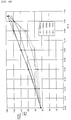
- a duty ratio is the same, a higher frequency can reduce drive torque as well as improve a charged voltage as shown in FIGS. 45 and 46.
- the embodiment can weaken a brake effect (brake torque) in the brake-OFF control as compared with the first embodiment, whereby the charged voltage can be more improved.
- FIG. 28 a fifth embodiment of the present invention will be described with reference to FIG. 28.
- the same numerals as used in the aforesaid respective embodiments are used to denote components similar or corresponding to those of the aforesaid embodiment and the description thereof is omitted or simplified.
- the embodiment is provided with a chopper signal generator 180 which includes high frequency chopper signal generation means 101 for outputting a high frequency chopper signal, low frequency chopper signal generation means 102 for outputting a low frequency chopper signal, a power supply voltage sensing circuit 103 as a voltage sensing unit for detecting the voltage of a power supply circuit 6 and switching means 104 for switching the output CH7 from the high frequency chopper signal generation means 101 and the output CH3 from the low frequency chopper signal generation means 102 in accordance with the voltage of the power supply circuit 6 and outputting the same.
- a chopper signal generator 180 which includes high frequency chopper signal generation means 101 for outputting a high frequency chopper signal, low frequency chopper signal generation means 102 for outputting a low frequency chopper signal, a power supply voltage sensing circuit 103 as a voltage sensing unit for detecting the voltage of a power supply circuit 6 and switching means 104 for switching the output CH7 from the high frequency chopper signal generation means 101 and the output CH
- the respective chopper signal generation means 101, 102 are arranged similarly to the chopper signal generator 180 of the second embodiment and includes three AND gates 182 - 184, two OR gates 186, 187, an AND gate 188 to which the output from the OR gate 187 and the output QD from a up/down counter 160 are input and a NOR gate 189 to which the output from the AND gate 188 and the output from the AND gate 184 are input.
- the high frequency chopper signal generation means 101 makes use of the outputs Q4 - Q7 of a dividing circuit 52, it can output the chopper signal CH7 which has a frequency higher than that of the chopper signal of the low frequency chopper signal generation means 102 which makes use of the outputs Q5 - Q8 of the dividing circuit 52.
- the power supply voltage sensing circuit 103 When the voltage charged to a power supply circuit (capacitor) 21a is lower than a set value, the power supply voltage sensing circuit 103 outputs a low-level signal, whereas when the voltage is higher than the set value, the power supply voltage sensing circuit 103 outputs a high-level signal.
- the switching means 104 includes two AND gates 105, 106 to which the signal from the power supply voltage sensing circuit 103 and the signals from the respective chopper signal generation means 101, 102 are input, respectively and an OR gate 107 to which the outputs from the AND gates 105, 106 are input.
- the output CH3 from the low frequency chopper signal generation means 102 is cancelled by the low-level signal by inverting the signal input to the AND gate 105 from the power supply voltage sensing circuit 103 so that the output CH7 from the high frequency chopper signal generation means 101 is output from the OR gate 107 to transistors 127, 129 as it is.
- a chopper brake control is carried out by the high frequency chopper signal CH7
- the chopper brake control is carried out by the low frequency chopper signal CH3 as shown in Fig. 29. Since the chopper signals CH3 and CH7 have the same duty ratio, respectively when a brake-ON control and a brake-OFF control are carried out, the high frequency chopper signal CH7 has lower drive torque and a higher charged voltage, that is, it can carry out a control giving priority to charging, whereas the low frequency chopper signal CH3 has higher drive torque and a lower charged voltage, that is, it can carry out a control giving priority to baking.
- the choppering signal need not be synchronized with the velocity set to a rotor 12 also in this embodiment.
- the embodiment can achieve operations and working-effects similar to (7) - (16) of the second embodiment.
- the chopper control can be carried out in correspondence to a charged state, whereby a more effective brake control can be carried out.
- the present invention is not limited to the above respective embodiments and modifications, improvements and the like within a range in which the object of the present invention can be achieved can be included in the present invention.
- the rotation control means 50 may be provided with an F/V (frequency/velocity) converter 100 which converts the output frequency of the waveform shaping circuit 70 into velocity information as shown in Fig. 30. Since the rotational velocity information of the generator 20 can be obtained by the provision of the F/V converter 100, the rotational velocity of the generator 20 can be controlled so that it approaches a set velocity, that is, a time standard signal. As a result, even if a waveform of generated power greatly varies instantly and deviates from a lock range, the control of the generator 20 can be maintained, by which a more stable system can be constructed.
- F/V frequency/velocity
- the chopper charging circuit 60 is not limited to the one disclosed in the above embodiments and, for example, a chopper charging circuit 110 composed of a comparator 111 for detecting the polarity of the rotor 12, diodes 112 for choppering the transistors 66, 67 and resistors 113 may be used as shown in FIG. 31.
- the power supply 63 is needed to supply the comparative reference voltage Vref to them. This embodiment, however, can make the power supply unnecessary.
- the transistors 66, 67 are driven by the coil terminal voltage through the diodes 112 in order to make the transistors 66, 67 conductive depending upon the polarity of a power generating coil they are driven.
- the coil terminal voltage must be made higher than a voltage which is obtained by adding a voltage (threshold voltage) Vth capable of driving the transistors 66, 67 to the rising-up voltage of the diodes 112.
- the chopper charging circuit may be arranged such that the transistors 66, 67 of the chopper charging circuit 60 shown in FIG. 6 are changed to a P-channel type, further the locations of the transistors 66, 67 are replaced with the locations of the diodes 68, 69 to thereby short circuit them to the + (VDD) of the capacitor 21a (first power supply line) so that the voltage of the capacitor 21a is boosted to a voltage less than the voltage of the VTKN when the transistors 66, 67 are released.
- the outputs from the comparators 61, 62 are ANDed with the output of the clock signal CLK by an AND circuit and input to the gates of the transistors 66, 67.
- the locations of the first and second switches 121, 122 may be replaced with the locations of the capacitor 123 and the diode 124 and disposed to the minus (VSS) side of the capacitor 21a (second power supply side). That is, the transistors 126 - 129 of the respective switches 121, 122 are changed to a N-channel type and inserted between the terminals MG1, MG2 of the generator 20 and the minus (VSS) side of the capacitor 21a as the power supply on the low voltage side (second power supply line side).
- the circuit is arranged to permit the switches 121, 122 connected to the negative terminal of the generator 20 to be continuously turned ON and the switches 121, 122 connected to the positive terminal thereof to be intermittently turned ON.
- a chopper charging circuit which simultaneously turns ON and OFF the transistors 66, 67 may be used to the first embodiment.
- chopper charging circuits 200, 300, 400, 500, 600 as shown in FIG. 32 - FIG. 36 may be used, respectively in the first embodiment.
- chopper charging circuits 200 - 600 components similar or corresponding to those of the above embodiments are denoted by the same numerals and the description thereof is omitted.
- the chopper charging circuit 200 shown in FIG. 32 is arranged such that a capacitor 201 in connected in series to the coil of the generator 20 as well as the capacitor 21a and an IC 202 are connected in parallel to the generator 20 and further a choppering switch 203 for executing choppering under the control of the IC 202 is connected in parallel to the generator 20.
- a parasitic diode 204 is connected in parallel to the switch 203.
- An effect similar to (2) of the first embodiment that the brake torque can be improved without dropping a charged voltage can be obtained also in the chopper charging circuit 200 because energy is charged to the capacitor 201 when a short-circuit brake is applied to the generator 20 by turning ON the switch 203 and power in which a generated voltage is increased by containing the energy of the capacitor 201 can be charged to the capacitor 21a when the switch 203 is turned OFF.
- the parasitic diode 204 also acts as the diode of a boosting/rectifying circuit, the number of parts can be reduced and a circuit mounting cost can be also decreased.
- the chopper charging circuit 300 shown in FIG. 33 is different from the chopper charging circuit 200 in that rectifying diodes 301, 302 are added to the chopper charging circuit 200.
- the chopper charging circuit 300 is inferior to the chopper charging circuit 200 in cost because it additionally includes the diodes 301, 302.
- the chopper charging circuit 200 has a drawback that when the switch 203 is connected and shortcircuited, since the charge of the capacitor 201 flows to the switch 203, a generated voltage improving ratio is reduced when a short-circuit time is increased.
- the chopper charging circuit 300 has an advantage that since it can prevent the charge of the capacitor 201 from flowing to the switch 203 when the switch 203 is connected, it can increase boosting performance as compared with the chopper charging circuit 200.
- the chopper charging circuit 400 shown in FIG. 34 is provided with an additional set of the switch 203 and the diodes 204, 302 used in the chopper charging circuit 300 in order to execute choppering to both the positive and negative waves of the a.c. output of the generator 20.
- a boosting and braking control can be carried out to the entire cycle of the a.c. output of the generator 20, whereby boosting performance and braking performance can be more increased.
- the chopper charging circuit 500 shown in FIG. 35 is a voltage doubler rectifying circuit capable of imposing a voltage twice as large as the voltage generated by the generator 20 on the IC 202 by the provision of two capacitors 501, 502.
- the chopper charging circuit 600 shown in FIG. 36 realizes choppering by a full wave rectifying circuit provided with rectifying diodes 601.
- these chopper charging circuit 500, 600 are arranged to carry out choppering to a full wave, they may be arranged to carry out choppering only to a half wave. These chopper charging circuits 300 - 600 can also obtain an effect similar to (2) of the first embodiment.
- the arrangement of the rotation sensing circuit 53, the LPF 55 and the brake control circuit 56 is not limited to the arrangement composed of the waveform shaping circuit 70, the charge pump 80 and the loop filter 81, the comparator 90, the dividing circuit 91 and the triangular wave generating circuit 92 as shown in the first embodiment and they may be suitably set when they are embodied.
- latch means 76 as shown in FIG. 37 may be used as the waveform shaping circuits 70.
- the respective waveform shaping circuits 70 shape the rectangular wave pulse fr only by the output from one of the comparators 61, 62 as shown in FIG. 9, a waveform shaping circuit 70 shown in FIG. 37 applies latch to the latch means 76 in response to the rising edge of the output for detecting the polarity of the terminal AG1 (comparator 62) and is reset in response to the output from the comparator 61 of the terminal AG2 as shown in FIG. 9.
- This arrangement has an advantage that a time is not delayed and detection can be correctly carried out, although two outputs must be used.
- latch is applied in response to the output of the terminal AG1, even if the output at the AG1 causes lack of pulse, it is ignored. Accordingly, an affect to the rectangular wave pulse fr can be prevented.
- the rotation control means is not limited to the one using the PLL control as shown in the first embodiment and the one using the up/down counter 160 as shown in the second to fifth embodiments and may control a rotational velocity only by the output from, for example, the F/V converter 100. Thus, it may be suitably set when it is embodied.
- the generator 20 is not limited to the two-pole rotor and may be a generator using a multi-pole rotor.
- the second to fifth embodiments use the 4-bit up/down counter 160 as the brake control means, an up/ down counter of 3 bits or less and an up/down counter of 5 bits or more may be used. Since the use of an up/down counter having a larger number of bits increases a countable value, a range in which a cumulated error can be stored can be increased, which is particularly advantageous in the control executed in a non-lock state just after the start of the generator 20, and the like.
- the use of a counter having a small number of bits has an advantage that a 1-bit counter can cope with the operation and a cost can be reduced, although a range in which a cumulated error can be stored is reduced, because an up-count and a down-count are repeated particularly in a lock state.
- the brake control means is not limited to the up/down counter and may be composed of first and second count means which are disposed to be used to the reference signal fs and the rotation sensing signal FG1, respectively and a comparison circuit for comparing the values counted by the respective count means.
- the use of the up/down counter 160 is advantageous in that it can simplify a circuit arrangement.
- any arrangement may be employed as the brake control means so long as it can detect the rotational cycle of the generator 20 and switch the brake-ON control and the brake-OFF control based on the rotational cycle. The specific arrangement thereof may be set when it is embodied.
- the brake control is carried out using the two types of the chopper signals having a different duty ratio and a different cycle in the above embodiment, three or more types chopper signals having a different duty ratio and a different cycle may be used.
- the specific arrangements of the voltage doubler rectifying circuit 35, the brake circuit 120, the brake control circuit 56, the chopper signal generator 180 and the like are not limited to those of the above respective embodiments and any arrangements may be used so long as they can chopper control the generator 20 of an electronically controlled mechanical timepiece.
- a diode 125a may be provided in place of the capacitor 123 as shown in FIG. 38 as the chopper rectifying circuit 35 of the brake circuit 120.
- the chopper rectifying circuit 35 functions as a simplified synchronized chopper rectifying circuit.
- the frequency of the chopper signal in the above respective embodiments may be suitably set when it is embodied.
- the cycle is, for example, 50 Hz or more (about five times as large as the rotational frequency of the rotor of the generator 20)
- brake performance can be improved while keeping a charged voltage to a prescribed value or more.
- the duty ratio of the chopper signal may be suitably set when it is embodied.
- the rotational frequency (reference signal) of the rotor is not limited to 10 Hz of the first embodiment and the 8 Hz of second embodiment and may be suitably set when it is embodied.
- a rotor rotation sensing circuit 800 as shown in FIG. 39 may be used to detect the rotation of the rotor as the rotation sensing circuit 53. That is, when the generator 20 is chopper controlled, a chopper pulse is superimposed on the rotational waveform of the rotor 12 of the generator 20. As a result, the voltage of the rotational waveform of the rotor 12 is compared with the reference voltage at the timing when the chopper waveform is superimposed in order to obtain a rectangular wave signal (rotor rotation sensing signal: MGOUT) which corresponds to a rotor rotational cycle from the rotational waveform of the rotor 12.
- MGOUT rotor rotation sensing signal
- noise such as an external magnetic field (for example, a commercial power supply having a frequency of 50/60 Hz) may be superimposed on the rotational waveform of the rotor 12 and there may arise such a case that the rotational waveform of the rotor 12 is deformed by being affected by the noise and a rotor rotation sensing signal cannot be obtained.
- noise such as an external magnetic field (for example, a commercial power supply having a frequency of 50/60 Hz) may be superimposed on the rotational waveform of the rotor 12 and there may arise such a case that the rotational waveform of the rotor 12 is deformed by being affected by the noise and a rotor rotation sensing signal cannot be obtained.
- the rotor rotation sensing circuit 800 is composed of a rotor pulse sensing circuit 801 for detecting whether the voltage of a rotor pulse exceeds a reference voltage (threshold voltage V ROTD, for example, 0.5 V) or not at a timing of choppering, a continuously detected number of times counter 802 for counting the number of times the voltage in excess of the reference voltage is continuously detected by the rotor pulse sensing circuit 801, a comparison circuit 803 for comparing the counter value of the continuously detected number of times counter 802 with a set value n (for example, 3 times) and detects whether the counter value is greater than the set value n or not, a continuously undetected number of times counter 804 for counting the number of times the voltage in excess of the reference voltage is not continuously detected by the rotor pulse sensing circuit 801, a comparison circuit 805 for comparing the counter value of the continuously undetected number of times counter 804 with a set value m (for example, 3 times) and detects whether the counter
- the rotor rotation sensing circuit 800 is arranged such that when the rotational waveform of the generator 20 in excess of the reference voltage (0.5 V) is continuously counted n times (3 times) in the comparison of the rotational waveform with the reference voltage at the timing of the chopper pulse, MGOUT is set to a low-level, whereas when it is not continuously detected m time (3 times), MGOUT is set to a high-level. With this operation, since MGOUT changes from the high-level to the low-level once while the rotor 12 rotates once, the rotation of the rotor can be reliably detected as shown in FIG. 40. MGOUT is compared with the reference signal (for example, 8 Hz) and a brake is applied in response to the difference therebetween to thereby regulate the velocity of the rotor 12.
- the reference signal for example, 8 Hz
- n, m may be suitably set when they are embodied, they may be particularly set based on the noise frequency superimposed on the rotational cycle of the rotor 12. For example, when 50 Hz noise (1 Vp-p sine wave) is superimposed on the 8 Hz rotational waveform (2 Vp-p sine wave) of the rotor 12 and the choppering frequency is 256 Hz, about 5 cycles of the choppering frequency is contained in the one cycle of the 50 Hz noise as shown in Fig. 41.
- the values n, m are set to 3 times in the embodiment.
- a rotor rotation sensing circuit provided, in place of the continuously undetected number of times counter 804, with a counter for counting the number of non-detected times of the rotational waveform in excess of the reference voltage regardless of that it continuously occurs or not may be employed as the rotor rotation sensing circuit 800.
- a value x for example, 2 times
- a value y for example, 5 times
- a value x for example, 2 times
- a value y for example, 5 times
- the detection of the rotation of the rotor 12 in consideration of the noise which is superimposed on the rotational waveform of the rotor 12 permits the rotation of the rotor 12 to be correctly detected even if a clock is used in an environment where noise is liable to occur.
- the use of the chopper rectifying circuit 35 shown in FIG. 15 and FIG. 38 is not limited to the electronically controlled mechanical timepiece of the above embodiments and it is applicable to timepieces such as various wrist watches, table clocks, clocks and the like, a portable sphygmomanometer, a portable phone, a pager, a pedometer, a pocket calculator, a portable personal computer, an electronic notebook, a portable radio and the like. In short, it can be widely used in electronic equipment which consumes electric power. Since an incorporated electronic circuit and a mechanical system can be driven by the generator 20 without a battery, battery replacement can be made unnecessary.
- a self-winding power generating mechanism and a self-power-generating device such as a solar cell, a thermo-power-generating device and the like.
- a chopper charging circuit 700 shown in FIG. 44 was used to the experiment of the example.
- the chopper charging circuit 700 was similar to the chopper charging circuit 300 shown in FIG. 33 and arranged such that a capacitor 201 of 0.1 mF was connected in series to the coil of a generator 20 as well as a capacitor 21a of 1 mF and a choppering switch were connected in parallel with the generator 20. Further, a resistor 205 of 10 MW was disposed in place of an IC as well as rectifying diodes 301, 302 were provided.
- the voltages charged to the capacitor 21a (generated voltages) and drive torque were measured at the respective values of a duty cycle (duty) which represents the turn-ON ratio of the switch 203 when the choppering frequency of the switch 203 was switched to 5 stages of frequencies, that is, to 25, 50, 100, 500, 1000 Hz.
- FIGS. 45 and 46 show the result of experiment, respectively.
- the rotational frequency of the rotor of a generator 20 was set to 10 Hz. Since an electronically controlled mechanical timepiece had an IC 202 which was ordinarily set so as to be driven by 0.8 V and 80 nA. When 0.8 V was charged to the capacitor 21a in the circuit 700, a current of 80 nA flowed to the resistor 205 of 10 MW so that a voltage sufficient to drive the IC 202 was charged.
- FIG. 46 shows the result of measurement of torque for driving the generator 20 under the choppering condition shown in FIG. 45.
- the drive torque is necessary to rotate the generator 20 at 10 Hz and similar to the torque by which the generator 20 applies a brake to a mainspring 1a.
- FIG. 46 it can be found that when the duty reaches 0.9, almost the same drive torque can be obtained, although the rising curves of the drive torque are different depending upon the choppering frequencies in the process of an increase of the duty.
- the choppering frequency is 50 Hz, that is, at least 5 times as large as the rotational frequency of the rotor, brake performance can be improved while maintaining the charged voltage to at least the prescribed value, whereby the effectiveness of the present invention has been confirmed.
- the choppering frequency is 25 Hz, at least 0.8 V can be charged when the duty is 0.80 or less. Accordingly, the choppering frequency of 25 Hz can be also used by suitably setting the value of the duty.
- the choppering frequency was measured only up to 1000 Hz in the experiment, it can be easily presumed that the same effect can be achieved by a larger choppering frequency.
- the choppering frequency is excessively large, the IC for choppering consumes a large amount of power and power to be generated by the generator is increased. Therefore, it is preferable to set the upper limit of the choppering frequency to 1000 Hz, that is, to about 100 times as large as the rotational frequency of the rotor.
- FIGS. 45 and 46 are not limited to the case that the rotational frequency (reference signal) of the rotor 12 of the generator 20 is 10 Hz and a similar tendency is also established in other frequencies. Accordingly, the rotational frequency may be suitably set when it is embodied and the same effect can be achieved in any rotational frequency.
- torque for controlling the generator can be increased while keeping generated power to at least a prescribed amount as well as a cost can be also reduced.
Abstract
Description
- The present invention relates to an electronically controlled mechanical timepiece for correctly driving hands fixed to a train wheel by converting the mechanical energy of a mechanical energy source such as a mainspring or the like into electric energy by a generator and controlling the rotational cycle of the generator by actuating rotation control means by the electric energy.
- There has been known an electronically controlled mechanical timepiece disclosed in Japanese Examined Patent Publication No. 7-119812 and Japanese Unexamined Patent Publication No. 8-101284 as an electronically controlled mechanical timepiece for correctly showing a time by accurately driving hands fixed to a train wheel by converting mechanical energy generated when a mainspring is released into electric energy by a generator and controlling the value of a current flowing to the coil of the generator by actuating rotation control means by the electric energy.
- Incidentally, in the electronically controlled mechanical timepiece arranged as described above, it is important to increase braking torque when the mainspring has high torque and prevent a drop of generated power at that time in order to increase an duration time.
- For this purpose, the electronically controlled mechanical timepiece disclosed in Japanese Examined Patent Publication No. 7-119812 provides an angular range where the rotating velocity of a rotor is increased by turning off a brake to thereby increase an amount of generated power each time the rotor rotates once, that is, each cycle of a reference signal and an angular range where the rotor is rotated at a low velocity by a brake applied thereto so that the generated power is increased when the rotor is rotated at the high velocity to thereby compensate the drop of the generated power when the brake is applied.
- Further, the electronically controlled mechanical timepiece disclosed in Japanese Unexamined Patent Publication No. 8-101284 increases braking torque and prevents a drop of a generated voltage at the same time by using a number of stages of a boosting circuit for boosting the voltage of the power induced by a generator.
- However, in the electronically controlled mechanical timepiece disclosed in Japanese Examined Patent Publication No. 7-119812, since the rotor must be switched from a state in which it rotates at a high rotating velocity to a state in which it rotates at a low rotating velocity so as to almost stop while it rotates once, there is a problem that it is actually difficult to realize such an abrupt velocity change. In particular, since the rotational stability of the rotor is ordinarily increased by the provision of a fly wheel, there is a problem that it is difficult to abruptly change the velocity.
- Further, since generated power is dropped at the time in which a brake is applied, it has a limit to suppress a drop of the generated power while increasing braking torque.
- On the other hand, since the electronically controlled mechanical timepiece disclosed in Japanese Unexamined Patent Publication No. 8-101284 requires a lot of switches and capacitors, it has a problem that a cost is increased.
- An object of the present invention is to provide an electronically controlled mechanical timepiece capable of increasing the braking torque of a generator while keeping generated power to at least a prescribed level as well as reducing a cost.
- In the present invention according to
claim 1, there is provided an electronically controlled mechanical timepiece including a mechanical energy source, a generator driven by the mechanical energy source coupled therewith through a train wheel for generating induced power and supplying electric energy from first and second terminals, hands coupled with the train wheel and rotation control means driven by the electric energy for controlling the rotational cycle of the generator characterized by comprising a switch capable of short circuiting the respective terminals of the generator, wherein the rotation control means provides chopper control of the generator by intermittently operating the switch. - The electronically controlled mechanical timepiece of the present invention drives the hands and the generator by the mainspring and regulates the number of rotation of a rotor, namely, the hands by applying a brake to the generator by the rotation control means.
- At the time, the rotation control (brake control) of the generator is carried out by chopper control of the generator by turning ON and OFF the switch capable of short circuiting both the ends of the coil of the generator. When the switch is turned ON, a short-circuit brake is applied to the generator by the chopper control as well as storing energy in the coil of the generator. Whereas, when the switch is turned OFF, the generator is operated and a voltage generated thereby is increased by the energy stored in the coil. As a result, when the generator is chopper controlled, a drop of the generated power which is caused when the brake is applied can be compensated by an increase of the generated voltage when the switch is turned OFF, whereby brake torque can be increased while keeping the generated power to at least a prescribed level so that there can be arranged an electronically controlled mechanical timepiece having a long operating duration.
- It is preferable that a choppering frequency for intermittently operating the switch by the rotation control means is at least 5 times as large as the waveform of the voltage generated by the rotor of the generator at a set velocity and it is more preferable that the choppering frequency is 5 to 100 times as large as the waveform of the voltage generated by the rotor of the generator at the set velocity.
- Since an effect for increasing the generated voltage is lowered when the choppering frequency is lower than 5 times the waveform of the generated voltage, it is preferable that the choppering frequency is at least 5 times as large as the waveform of the generated voltage.
- When the choppering frequency is at least 100 times as large as the waveform of the generated voltage, an IC for executing choppering consumes a large amount of power. Thus, it is preferable that the choppering frequency is 100 times or less the waveform of the generated voltage. Further, when the choppering frequency is 5 times to 100 times as large as the waveform of the generated voltage, since the changing ratio of torque to the changing ratio of a duty cycle approaches a prescribed level, the control can be easily carried out. However, the choppering frequency may be set to less than 5 times or greater than 100 times depending upon a use and a control method.
- It is preferable that an electronically controlled mechanical timepiece according to
claim 4 comprises first and second power supply lines for charging the electric energy of the generator to a power supply circuit, wherein the switch is composed of first and second switches interposed between the first and second terminals of the generator and one of the first and second power source lines, respectively and the rotation control means continuously turns ON the switch connected to one of the first and second terminals of the generator as well as intermittently operates the switch connected to the other terminal of the generator. - With this arrangement, since the power generating processing and the rotation processing of the generator can be simultaneously carried out in addition to the brake control by the choppering, a cost can be reduced by decreasing the number of parts as well as a power generating efficiency can be improved by controlling a timing at which the respective switches are intermittently operated.
- At the time, it is preferable that the first and second switches are composed of respective transistors.
- Further, it is preferable that the rotation control means comprises a comparator for comparing the waveforms of the voltage generated by the generator with a reference waveform, a comparison circuit for comparing the output from the comparator with a time standard signal and outputting a difference signal, a signal output circuit for outputting a pulse-width varied clock signal based on the difference signal, and a logic circuit for ANDing the clock signal and the output from the comparator and outputting an ANDed signal to the transistors.
- With this arrangement, since power consumed to intermittently control the transistors can be reduced, a circuit can be arranged so that it is suitable for a generator of a clock which generates a small amount of power.
- In an electronically controlled mechanical timepiece according to
claim 7, the first switch is composed of a first field effect transistor having a gate connected to the second terminal of the generator and a second field effect transistor connected in series to the first field effect transistor and intermittently operated by the rotation control means, the second switch is composed of a third field effect transistor having a gate connected to the first terminal of the generator and a fourth field effect transistor connected in series to the third field effect transistor and intermittently operated by the rotation control means and first and second diodes are interposed between the first and second terminals of the generator and the other of the first and second power supply lines, respectively. - In an electronically controlled mechanical timepiece according to
claim 8, the first switch is composed of a first field effect transistor having a gate connected to the second terminal of the generator and a second field effect transistor connected in series to the first field effect transistor and intermittently operated by the rotation control means, the second switch is composed of a third field effect transistor having a gate connected to the first terminal of the generator and a fourth field effect transistor connected in series to the third field effect transistor and intermittently operated by the rotation control means, a boost capacitor is interposed between one of the first and second terminals of the generator and the other of the first and second power supply lines and a diode is interposed between the other of the first and second terminals and the other of the first and second power supply lines. - In the electronically controlled mechanical timepiece arranged as described above, when the first terminal of the generator is set to plus and the second terminal thereof is set to minus (a potential lower than that of the first terminal), the first field effect transistor whose gate is connected to the second terminal is turned ON and the third field effect transistor whose gate is connected to the first terminal is turned OFF. As a result, the a.c. current generated by the generator flows through the path composed of the first terminal, the first field effect transistor, one of the first and second power supply lines, the power supply circuit, the other of the first and second power supply lines and the second terminal.
- When the second terminal of the generator is set to plus and the first terminal thereof is set to minus (a potential lower than that of the second terminal), the third field effect transistor whose gate is connected to the first terminal is turned ON and the first field effect transistor whose gate is connected to the second terminal is turned OFF. As a result, the a.c. current generated by the generator flows through the path composed of the second terminal, the third field effect transistor, one of the first and second power supply lines, the power supply circuit, the other of the first and second power supply lines and the first terminal.
- The second and fourth field effect transistors repeat the ON- and OFF-states in response to the choppering signals input to their gates. Since the second and fourth field effect transistors are connected in series to the first and third field effect transistors, when the first and third field effect transistors are turned ON, a current flows regardless of the turned-ON/OFF states of the second and fourth field effect transistors. However, when the first and third field effect transistors are turned OFF, the current flows when the second and fourth field effect transistors are turned ON in response to a chopper signal. Therefore, when the second and fourth field effect transistors, which are connected in series to one of the first and third field effect transistors in the turned-OFF state, are turned ON in response to the choppering signal, both the first and second switches are turned ON to thereby short circuit the respective terminals of the generator.
- With this operation, the generator can be subjected to a brake control by chopper control so that a drop of generated power when the brake is applied can be compensated by an increase of a generated voltage when the switch is turned OFF, whereby brake torque can be increased while keeping the generated power to at least a prescribed level so that there can be provided an electronically controlled mechanical timepiece having a long operating duration. Further, since the generator is rectified by the first and third field effect transistors whose gates are connected to the respective terminals, a comparator and the like need not be used, whereby the arrangement is simplified as well as a drop of a charging efficiency due to the power consumed by the comparator can be prevented. Further, since the field effect transistors are turned ON and OFF making use of the terminal voltage of the generator, the respective field effect transistors can be controlled in synchronism with the polarities of the terminals of the generator, whereby a rectifying efficiency can be improved.
- When a boost capacitor is interposed between one of the terminals of the generator and a power supply line as disclosed in the electronically controlled mechanical timepiece according to
claim 8, the power supply circuit and the boost capacitor can be simultaneously charged when the terminal voltage of the terminal to which the capacitor is connected is increased. Whereas, when the voltage of the other of the terminals of the generator is increased, the power supply circuit can be charged with a high voltage obtained by adding the voltage charged to the boost capacitor to the voltage induced by the generator. - In an electronically controlled mechanical timepiece according to
claim 9, the rotation control means comprises a chopper signal generator for generating at least two types of chopper signals having a different duty ratio and at least the two types of the chopper signals having a different duty ratio are imposed on the switch to thereby provide chopper control of the generator. - In the present invention, when the switch capable of short circuiting both the terminals of the generator is provided and the generator is chopper controlled by applying the choppering signal to the switch, although a lower chopper frequency and a higher duty ratio can increase drive torque (brake torque) more and a higher chopper frequency increases a charged voltage (generated voltage), they are not so much reduced even if the duty ratio is increased and a point has been found where the charged voltage is increased until the duty ratio is equal to about 0.8 when the chopper frequency is at least 50 Hz. Thus, the generator is chopper controlled using at least the two chopper signals having a different duty ratio.
- It is preferable that the rotation control means comprises brake control means for switching a brake-ON control for detecting the rotational cycle of the generator and applying a brake to the generator based on the rotational cycle and a brake-OFF control for releasing the brake, the brake control means applies the chopper signals having a different duty ratio on the switch in the brake-ON control and the brake-OFF control and the chopper signal applied in the brake-ON control has a duty ratio larger than that of the chopper signal applied in the brake-OFF control.
- The electronically controlled mechanical timepiece of the present invention drives the hands and the generator by the mainspring and regulates the number of revolutions of the rotor, namely, the hands by applying a brake to the generator by the rotation control means.
- At the time, the rotation control of the generator is carried out by imposing a chopper signal on the switch capable of short circuiting both the ends of the coil of the generator and turning ON and OFF the switch, that is, by chopper control of the switch. When the switch is turned ON by the chopper control, a short-circuit brake is applied to the generator as well as storing energy in the coil of the generator. Whereas, when the switch is turned OFF, the generator is operated and a voltage generated thereby is increased by the energy stored in the coil. As a result, when the generator is controlled by the choppering in the application of a brake thereto, a drop of the generated power which is caused when the brake is applied can be compensated by an increase of the generated voltage when the switch is turned OFF, whereby brake torque can be increased while suppressing a drop of the generated power so that there can be arranged an electronically controlled mechanical timepiece having a long operating duration.
- When the brake-ON control in which the brake must be applied is carried out by imposing at least the two types of chopper signals having a different duty ratio on the switch, the control torque of the generator can be increased as well as a drop of the generated power can be suppressed by chopper control by imposing a chopper signal having a large duty ratio (in which the switch is turned ON a longer time).
- On the other hand, in the brake-OFF control in which the brake is released, the brake torque of the generator can be greatly reduced as well as the generated power can be sufficiently obtained by imposing a chopper signal having a duty ratio smaller than that of the above mentioned chopper signal.
- The application of the brake by means of the chopper signal having the large duty ratio and the release thereof by means of the chopper signal having the small duty ratio permit an increase of the brake torque while suppressing a drop of the generated power (power charged to a capacitor and the like), whereby an electronically controlled mechanical timepiece having a long operating duration can be provided.
- Although the brake-ON control and the brake-OFF control are ordinarily carried out once in each reference cycle of the generator (the cycle during which the rotor rotates once, or the like), only the brake-OFF control may be carried out during a plurality of the reference cycles just after the start of the generator and the like.
- Further, although the duty ratio of the respective chopper signals may be suitably set in accordance with the characteristics and the like of the generator to be controlled, it suffices only to use a chopper signal having a large duty ratio of, for example, about 0.7 - 0.95 and a chopper signal having a small duty ratio of about, for example, 0.1 - 0.3.
- In an electronically controlled mechanical timepiece according to
claim 11, the rotation control means comprises a chopper signal generator for generating a chopper signal and brake control means for switching a brake-ON control for detecting the rotational cycle of the generator and applying a brake to the generator based on the rotational cycle and a brake-OFF control for releasing the brake and the brake control means imposes the chopper signal on the switch only in the brake-ON control to thereby chopper control the generator. - Since the choppering signal is imposed only in the brake-ON control which needs to control a brake also in this case, the brake torque of the generator can be increased as well as a drop of generated power can be suppressed by chopper control.
- Further, in an electronically controlled mechanical timepiece according to
claim 12, the rotation control means comprises a chopper signal generator for generating at least two types of chopper signals having a different frequency and at least the two types of the chopper signals having a different frequency are imposed on the switch to thereby chopper control the generator. - It is preferable that the rotation control means comprises brake control means for switching a brake-ON control for detecting the rotational cycle of the generator and applying a brake to the generator based on the rotational cycle and a brake-OFF control for releasing the brake, wherein the brake control means imposes the chopper signals having a different frequency on the switch in the brake-ON control and the brake-OFF control and the chopper signal imposed in the brake-ON control has a frequency smaller than that of the chopper signal imposed in the brake-OFF control.
- When the chopper signal imposed on the switch has a high frequency, the drive torque (brake torque) is reduced so that a braking effect is decreased as well as the charged voltage (generated voltage) is increased. On the other hand, when the chopper signal having a low frequency is imposed, the drive torque is increased and the braking effect is increased as well as the charged voltage is reduced as compared with the case that the frequency is high. However, since the choppering is carried out, the charged voltage is increased as compared with a case that only a brake control is simply executed.
- Therefore, in the brake-ON control in which the brake must be applied, the brake torque of the generator can be increased by imposing the chopper signal having the low frequency as well as a drop of the generated power can be suppressed by the choppering.
- On the other hand, in the brake-OFF control in which the brake is released, the brake torque of the generator can be greatly reduced by imposing the chopper signal having a frequency which is higher than that of the above mentioned chopper signal on the switch, whereby generated power can be sufficiently obtained.
- The brake torque can be increased while suppressing a drop of the generated power by applying the brake using the chopper signal having the low frequency and releasing the brake using the chopper signal having the high frequency, whereby an electronically controlled mechanical timepiece having a long operating duration can be arranged.
- Although the frequency of the respective chopper signals may be suitably set in accordance with the characteristics and the like of the generator to be controlled, it suffices only to use a chopper signal having a high frequency of for example, about 500 - 1000 Hz and a chopper signal having a low frequency of, for example, about 10 - 100 Hz.
- Further, the chopper control may be carried out using chopper signals having not only a different frequency but also a different duty ratio. In particular, when a chopper signal having a low frequency and a high duty ratio is used in the brake-ON control and a chopper signal having a high frequency and a low duty ratio is used in the brake-OFF control, the brake control can be effectively carried out.
- In an electronically controlled mechanical timepiece according to
claim 15, the rotation control means comprises a chopper signal generator for generating at least two types of chopper signals having a different frequency and a voltage sensing unit for detecting the voltage of a power supply charged by the generator, wherein the voltage of the power supply detected by the voltage sensing unit is lower than a set value, a chopper signal having a first frequency is imposed on the switch, whereas when the detected voltage of the power supply is higher than the set value, a chopper signal having a second frequency which is lower than the first frequency is imposed on the switch to thereby chopper control the generator. - It is preferable that the rotation control means comprises brake control means for switching a brake-ON control for detecting the rotational cycle of the generator and applying a brake to the generator based on the rotational cycle and a brake-OFF control for releasing the brake, the chopper signal generator can generate two types of chopper signals having a different duty ratio at first and second frequencies, and the brake control means imposes chopper signals having one of first and second frequencies which is selected in correspondence to the power supply voltage and a different duty ratio to the switch in the brake-ON control and the brake-OFF control, respectively.
- In the present invention arranged as described above, the chopper signal for executing the brake control of the generator is switched to a chopper signal having a different frequency in accordance with the power supply voltage (voltage charged to the capacitor by the generator, or the like). Accordingly, when the power supply voltage is lower than a set value, a chopper signal which makes the brake torque low and the charged voltage high, that is, which gives priority to charging rather than a braking effect is imposed, whereas when the power supply voltage is higher than the set value, a chopper signal which makes the brake torque high and the charged voltage low, that is, which gives priority to the brake rather than a charging effect is imposed so that a proper brake control can be carried out in accordance with a charged state.
- Further, it is preferable that the rotation control means synchronizes a timing at which the brake-ON control for applying the brake to the generator and the brake-OFF control for releasing the brake are switched with a timing at which the switch is intermittently operated in response to the chopper signal.
- When the timing of the brake is synchronized with the timing of the chopper signal, the chopper signal can be also used as a pace measuring pulse.
- In an electronically controlled mechanical timepiece according to claim 18, the rotation control means comprises rotational cycle sensing means for detecting the rotational cycle of the rotor by means of a rotor rotation sensing signal which is set to one of a low-level and a high-level when the voltage of the rotational waveform of the generator is compared with a reference voltage at a timing of choppering and the voltage of the rotational waveform is equal to or lower than the reference voltage and to the other of the low-level and the high-level when the voltage of the rotational waveform is higher than the reference voltage.
- It is preferable that the rotation control means sets the rotor rotation sensing signal to one of the low-level and the high-level when the voltage of the rotational waveform of the generator which is compared with the reference voltage at the timing of choppering is continuously equal to or lower than the reference voltage by n times, where n is an integer, and sets the rotor rotation sensing signal to the other of the low-level and the high-level when the voltage of the rotational waveform of the generator which is compared with the reference voltage at the timing of choppering is continuously higher than the reference voltage by m times, where m is an integer. In addition, it is preferable that the n times and the m times are set based on a choppering frequency and a noise frequency superimposed on the rotational waveform of the rotor respectively.
- When the generator is chopper controlled, a chopper pulse is superimposed on the rotational waveform of the rotor of the generator. Therefore, the voltage of the rotational waveform of the rotor is compared with the reference voltage at the timing when the chopper pulse is superimposed (timing at which the choppering is executed) in order to obtain a rectangular wave signal (rotor rotation sensing signal) which corresponds to the rotational cycle of the rotor from the rotational waveform of the rotor. Noise such as an external magnetic field (for example, a commercial power supply having a frequency of 50/60 Hz) and the like may be superimposed on the rotational waveform of the rotor and there may arise such a case that the rotational waveform of the rotor is deformed by the effect of the noise and a rotor rotation sensing signal cannot be correctly obtained.
- To cope with this problem, whether the rotational waveform of the rotor is equal to or less than the reference voltage or greater than it can be correctly and reliably detected so that the erroneous detection of the rotor rotation sensing signal caused by the effect of the noise can be prevented by setting the rotor rotation sensing signal to one of the low-level and the high-level when the voltage of the rotational waveform of the generator is continuously equal to or lower than the reference voltage by n times and setting the rotor rotation sensing signal to the other of the low-level and the high-level when the voltage of the rotational waveform of the generator which is compared with the reference voltage at the timing of choppering is continuously higher than the reference voltage by m times.
- Further, the rotation control means may set the rotor rotation sensing signal to one of the low-level and the high-level when the voltage of the rotational waveform of the generator which is compared with the reference voltage at the timing of choppering is continuously equal to or lower than the reference voltage by x times, where x is an integer, and set the rotor rotation sensing signal to the other of the low-level and the high-level when the rotational waveform of the generator which is compared with the reference voltage at the timing of choppering is higher than the reference voltage by y times (which may be not continuous) and where y is an integer. It is preferable here that the x times and the y times are set based on a choppering frequency and a noise frequency superimposed on the rotational waveform of the rotor.
- Whether the rotational waveform of the rotor is equal to or less than the reference voltage or greater than it can be correctly and reliably detected and the erroneous detection of the rotor rotation sensing signal caused by the effect of the noise can be prevented also in this case.
- Further, the rotation control means may control the rotation of the rotor using a PLL control and may control the rotation of the rotor using an up/down counter. In short, the rotation control means may control the rotation of the rotor using any means so long as it preferably compares the rotational waveform of the rotor with the reference waveform from a quartz oscillator and carries out the brake control of the generator so as to reduce the difference therebetween.
- According to a method of controlling an electronically controlled mechanical timepiece of the present invention including a mechanical energy source, a generator driven by the mechanical energy source coupled therewith through a train wheel for generating induced power and supplying electric energy from a first and second terminals, hands coupled with the train wheel and rotation control means driven by the electric energy for controlling the rotational cycle of the generator, the method comprises the steps of comparing a reference signal generated based on a signal from a time standard source with a rotation sensing signal output in correspondence to the rotational cycle of the generator, intermittently operating a switch capable of short circuiting the respective terminals of the generator in accordance with an amount of advance of the rotation sensing signal with respect to the reference signal and subjecting the generator to a brake control by choppering.
- According to the above control method, since the rotation control (brake control) of the generator is carried out by choppering by turning ON and OFF the switch capable of shorting both the ends of the coil of the generator, a drop of generated power which is caused when the brake is applied can be compensated by an increase of the generated voltage when the switch is turned OFF, whereby control torque can be increased while keeping the generated power to at least a prescribed level so that there can be arranged an electronically controlled mechanical timepiece having a long operating duration.
- In a method of controlling an electronically controlled mechanical timepiece according to claim 26 including a mechanical energy source, a generator driven by the mechanical energy source coupled therewith through a train wheel for generating induced power and supplying electric energy from a first and second terminals, hands coupled with the train wheel and rotation control means driven by the electric energy for controlling the rotational cycle of the generator, the method comprising the steps of inputting a reference signal generated based on a signal from a time standard source and a rotation sensing signal output in correspondence to the rotational cycle of the generator to an up/down counter by setting one of them as an up-count signal and the other of them as a down-count signal, applying a brake to the generator by choppering when the counter value of the up/down counter is equal to a preset value and not applying the brake thereto when the counter value is equal to a value other than the preset value.
- According to the above control method, when the counter value of the up/down counter is equal to the set value, that is, when the torque of the mechanical energy source such as a mainspring or the like is increased and the rotation of the generator is advanced, a brake is continuously applied by choppering until the difference between respective count values disappears. As a result, brake torque can be increased while keeping generated power to at least a prescribed level, whereby a rotational velocity can be promptly and correctly regulated so that a control can be executed with excellent responsiveness. Further, since counting and the comparison of respective count values can be carried out at the same time by means of the up/down counter, the arrangement can be simplified as well as the difference between the respective count values can be simply determined.
- Embodiments of the present invention will now be described by way of further example only and with reference to the accompanying drawings, in which:-
- FIG. 1 is a plan view showing a main portion of an electronically controlled mechanical timepiece according to a first embodiment of the present invention.
- FIG. 2 is a sectional view showing a main portion of FIG. 1.
- FIG. 3 is a sectional view showing a main portion of FIG. 1.
- FIG. 4 is a block diagram showing a function of the first embodiment.
- FIG. 5 is a block diagram showing an arrangement of the fist embodiment.
- FIG. 6 is a circuit diagram showing a chopper charging circuit of the first embodiment.
- FIG. 7 is a view showing an example of a waveform shaping circuit of the first embodiment.
- FIG. 8 a view showing another example of the waveform shaping circuit of the first embodiment.
- FIG. 9 is a waveform view in a circuit of the first embodiment.
- FIG. 10 is a view showing processing executed by a comparator of a brake control circuit of the first embodiment.
- FIG. 11 is a flowchart showing a control method of the first embodiment.
- FIG. 12 is a timing chart in the first embodiment.
- FIG. 13 is a block diagram showing an arrangement of a main portion of an electronically controlled mechanical timepiece of a second embodiment of the present invention.
- FIG. 14 is a circuit diagram showing an arrangement of the electronically controlled mechanical timepiece of the second embodiment.
- FIG. 15 is a circuit diagram showing an arrangement of a rectifying circuit of the second embodiment.
- FIG. 16 is a timing chart in an up/down counter of the second embodiment.
- FIG. 17 is a timing chart in a chopper signal generating unit of the second embodiment:
- FIG. 18 is a view showing an output waveform of a generator of the second embodiment.
- FIG. 19 is flowchart showing a control method of the second embodiment.
- FIG. 20 is a timing chart in the second embodiment.
- FIG. 21 is a view showing an output waveform of a generator as a comparative example of the second embodiment.
- FIG. 22 is a circuit diagram showing an arrangement of an electronically controlled mechanical timepiece of a third embodiment.
- FIG. 23 is a view showing an output waveform of a generator of the third embodiment.
- FIG. 24 is a timing chart in the third embodiment.
- FIG. 25 is a circuit diagram showing an arrangement of a electronically controlled mechanical timepiece of a fourth embodiment.
- FIG. 26 is a timing chart in a circuit of the fourth embodiment.
- FIG. 27 is a view showing an output waveform of a generator of the fourth embodiment.
- FIG. 28 is a circuit diagram showing an arrangement of an electronically controlled mechanical timepiece of a fifth embodiment.
- FIG. 29 is a timing chart in a circuit of the fifth embodiment.
- FIG. 30 is a block diagram showing an arrangement of a modification of the present invention.
- FIG. 31 is a circuit diagram showing a modification of the chopper charging circuit of the present invention.
- FIG. 32 is a circuit diagram showing a modification of the chopper charging circuit of the present invention.
- FIG. 33 is a circuit diagram showing a modification of the chopper charging circuit of the present invention.
- FIG. 34 is a circuit diagram showing a modification of the chopper charging circuit of the present invention.
- FIG. 35 is a circuit diagram showing a modification of the chopper charging circuit of the present invention.
- FIG. 36 is a circuit diagram showing a modification of the chopper charging circuit of the present invention.
- FIG. 37 is a view showing a modification of the waveform shaping circuit of the present invention.
- FIG. 38 is a circuit diagram showing a modification of the chopper rectifying circuit of the present invention.
- FIG. 39 is a view showing an arrangement of a modification of a rotor rotation sensing circuit of the present invention.
- FIG. 40 is a view describing an operation of the rotor rotation sensing circuit.
- FIG. 41 is a waveform view showing a rotating waveform of a rotor.
- FIG. 42 is a view describing an operation of another rotor rotation sensing circuit.
- FIG. 43 is a waveform view showing another rotating waveform of a rotor.
- FIG. 44 is a circuit diagram showing a chopper charging circuit in an experimental example of the present invention.
- FIG. 45 is a graph showing the relationship between a choppering frequency and a charged voltage in the experimental example of the present invention; and
- FIG. 46 is a graph showing the relationship between a choppering frequency and braking torque in the experimental example of the present invention.
- FIG. 1 is a plan view showing a main portion of an electronically controlled mechanical timepiece according to a first embodiment of the present invention and FIG. 2 and FIG. 3 are sectional views thereof.
- The electronically controlled mechanical timepiece includes a
movement barrel 1 composed of a mainspring 1a, a barrel gear 1b, a barrel arbor 1c and a barrel lid 1d. The mainspring 1a has an outer end fixed to the barrel gear 1b and an inner end fixed to the barrel arbor 1c. The barrel arbor 1c is supported by amain plate 2 and awheel train receiver 3 and fixed by aratchet wheel screw 5 so as to be rotated together with the aratchet wheel 4. - The
ratchet wheel 4 is meshed with adetent 6 so that it is rotated clockwise and is not rotated counterclockwise. Since a method of winding the mainspring 1a by rotating theratchet wheel 4 clockwise is similar to a winding method using an automatic or manual winding mechanism for a mechanical timepiece, the description of the method is omitted. - The rotation of the barrel gear 1b is transmitted to a
second wheel 7 after its velocity is increased to 7 times the initial velocity thereof and further successively transmitted to athird wheel 8 after its velocity is increased to 6.4 times, to afourth wheel 9 after its velocity is increased to 9.375 times, to afifth wheel 10 after its velocity is increased to 3 times, to asixth wheel 11 after its velocity is increased to 10 times and finally to arotor 12 after its velocity is increased to 10 times. That is, the rotation of the barrel gear 1b is increased to 126,000 times in total. - A
canon pinion 7a is fixed to thesecond wheel 7, aminute hand 13 is fixed to thecanon pinion 7a and asecond hand 14 is fixed to thefourth wheel 9, respectively. Therefore, therotor 12 must be controlled to rotate at 5 rpm in order to rotate thesecond wheel 7 at 1 rpm and thefourth wheel 9 at 1 rpm. At the time, the barrel gear 1b rotates at 1/7 rpm. - The electronically controlled mechanical timepiece includes a
generator 20 composed of therotor 12, astator 15 and acoil block 16. Therotor 12 is composed of arotor magnet 12a, arotor pinion 12b and arotor inertia disc 12c. Therotor inertia disc 12c is used to reduce a variation in the number of rotations of therotor 12 with respect to a variation in the drive torque from themovement barrel 1. Thestator 15 is composed of astator body 15a and astator coil 15b wound therearound in an amount of 40000 turns. - The
coil block 16 is composed of amagnetic core 16a and acoil 16b wound therearound in an amount of 110000 turns. Thestator body 15a and themagnetic core 16a are composed of PC Permalloy or the like. Thestator coil 15b and thecoil 16b are connected in series to each other so that they can output a voltage obtained by adding the voltages generated thereby. - Next, a control circuit of the electronically controlled mechanical timepiece will be described with reference to FIGS. 4 to 9.
- FIG. 4 is a block diagram showing a function of the embodiment.
- The AC output from the
generator 20 is boosted and rectified through a rectifyingcircuit 21 which executes boosting and rectification, full wave rectification, half wave rectification, transistor rectification and the like. Aload 22 such as an IC for controlling rotation control means and the like, a quartz oscillator and the like is connected to the rectifyingcircuit 21. FIG. 4 shows respective functional circuits arranged in an IC separately from theload 22 for the convenience of description. - Connected to the
generator 20 is abraking circuit 23 to which abraking resistor 23A and an N-channel or P-channel type transistor 23B functioning as a switch are connected in series. A VCO (voltage control oscillator) 25 is composed of thegenerator 20 and thebraking circuit 23. A diode may be suitably inserted into thebraking circuit 23 in addition to thebraking resistor 23A. - Rotation control means 50 is connected to the
VCO 25. - The rotation control means 50 is composed of an
oscillating circuit 51, a dividingcircuit 52, arotation sensing circuit 53 for detecting the rotation of therotor 12, a phase comparison circuit (PC) 54, a low pass filter (LPF) 55 and abrake control circuit 56. - The
oscillating circuit 51 outputs an oscillating signal generated by aquartz oscillator 51A and the oscillating signal is divided up to a prescribed frequency by the dividingcircuit 52. The divided signal is output to thephase comparison circuit 54 as a time standard signal (reference frequency signal) fs of, for example, 100 Hz. The reference signal may be created using various types of reference standard oscillation sources in place of thequartz oscillator 51A. - The
rotation sensing circuit 53 receives the output waveform from theVCO 25 at high impedance so that thegenerator 20 side is not affected thereby, converts the output to a rectangular wave pulse fr and outputs the same to thephase comparison circuit 54. - The
phase comparison circuit 54 compares the phase of the time standard signal fs from the dividingcircuit 52 with that of the rectangular wave pulse fr from therotation sensing circuit 53 and outputs a difference signal as a difference therebetween. The difference signal is input to thebrake control circuit 56 after its high frequency component is removed by theLPF 55. - The
brake control circuit 56 inputs the control signal from thebraking circuit 23 to theVCO 25 based on the above signal, by which a phase synchronous control (PLL control) is realized. - Next, FIG. 5 shows a more specific arrangement of the embodiment.
- In the embodiment, a
chopper charging circuit 60 is used as thebraking circuit 23 as shown in the figure. As shown in FIG. 6, thechopper charging circuit 60 is composed of twocomparators coils generator 20, apower supply 63 for supplying a comparison reference voltage Vref to thecomparators circuits comparators brake control circuit 56, field effect transistors (FETs) 66, 67 which are connected to thecoils OR circuits diodes coils capacitor 21a disposed to the rectifyingcircuit 21. TheFET parasitic diodes - The + side (first power supply line side) of the
capacitor 21a is set to a voltage VDD and the - side thereof (second power supply line side) is set to a VTKN (V/TANK/Negative: the - side of a battery). Likewise, the - side of thepower supply 63 and the source sides oftransistors chopper charging circuit 60 executes chopper boosting by short-circuiting thegenerator 20 once to the VTKN side by controlling thetransistors generator 20 is made higher than the voltage VDD when thetransistors comparators - In the
chopper charging circuit 60, the outputs from thecomparators waveform shaping circuit 70. Accordingly, therotation sensing circuit 53 is composed of thechopper charging circuit 60 and thewaveform shaping circuit 70. - There can be used a monostable multivibrator (one shot type) 71 composed of a
capacitor 72 and aresistor 73 as shown in FIG. 7, a type using acounter 74 and alatch 75 as shown in FIG. 8, or the like as thewaveform shaping circuit 70. - The
phase comparison circuit 54 is composed of an analog phase comparator, a digital phase comparator and the like and a CMOS type phase comparator using a CMOS IC or the like can be used. Thephase comparison circuit 54 detects a phase difference between the time standard signal fs of 10 Hz from the dividingcircuit 52 and the rectangular wave pulse fr from thewaveform shaping circuit 70 and outputs a difference signal. - The difference signal is input to a charge pump (CP) 80 and converted into a voltage level and a high frequency component is removed therefrom by a
loop filter 81 composed of aresistor 82 and a capacitor 83. Therefore, theLPF 55 is composed of thecharge pump 80 and theloop filter 81. - The level signal "a" output from the
loop filter 81 is input to acomparator 90. There is input a triangular signal b to thecomparator 90 which is obtained by converting the signal from theoscillating circuit 51 through a triangularwave generating circuit 92 which uses adividing circuit 91 for dividing the signal from theoscillating circuit 51 to 50 Hz - 100 KHz, an integrator and the like. Thecomparator 90 outputs a rectangular wave pulse signal "c" in response to the level signal "a" from theloop filter 81 and the triangular signal "b". Therefore, thebrake control circuit 56 is composed of thecomparator 90, the dividingcircuit 91 and the triangularwave generating circuit 92. - The rectangular wave pulse signal "c" output from the
comparator 90 is input to thechopper charging circuit 60 as a clock signal CLK as described above. - Next, an operation of the embodiment will be described with reference to the waveform views of FIGS. 9, 10 and the flowchart of FIG. 11.
- When the
rotor 12 of thegenerator 20 is rotated by the mainspring la, a.c. waveforms are output from thecoils comparators power supply 63. A timing of polarity for turning ON thetransistors comparators - That is, boosting and charging to the
capacitor 21a and a chopper braking operation of thegenerator 20 can be carried out only by inputting the clock signal CLK to the gates of thetransistors transistors capacitor 21a is charged through one of theparasitic diodes diodes capacitor 21a is charged through a path from theparasitic diode 67A to thediode 68 through thecoils capacitor 21a is charged through a path from theparasitic diode 66A to thediode 69 through thecoils - In this case, since the two diodes are connected in series in the charging path, a voltage is dropped by an amount obtained by adding the rising-up voltages VF of the respective diodes. Therefore, the
capacitor 21a cannot be charged unless a charging voltage is higher than a voltage obtained by adding the amount of the voltage drop to the potential of thecapacitor 21a. This is a large factor for lowering a charging efficiency in a generator used in an electronically controlled mechanical timepiece which generates a small amount of a voltage. - To cope with the above problem, the embodiment improves the charging efficiency by regulating the timing of the
transistors - That is, when the terminal AG1 is made to + when viewed from the VTKN and exceeds the voltage Vref, the
comparator 61 outputs a high-level signal so that theOR circuit 65 continuously outputs a high-level signal regardless of the clock signal CLK, whereby thetransistor 67 is turned ON by a voltage applied to the gate thereof. - On the other hand, the
comparator 61 connected to the terminal AG2 outputs a low-level signal due to AG2 < voltage Vref, theOR circuit 64 outputs a signal which is synchronized with the clock signal, thetransistor 66 repeats an ON/OFF operation and the terminal AG1 is chopper boosted. - The charging path at the time is set to AG1 - diode 68 -
capacitor 21a - VTKN - transistor 67 (from source to drain) - AG2 and theparasitic diode 67A is removed from the path, when thetransistor 66 is turned on once and then turned off, whereby a voltage drop is reduced and the charging efficiency is improved. - It is preferable to select, as the level of the voltage Vref, a generated voltage level which permits the voltage generated by the
generator 20 to be chopper boosted and charged to thecapacitor 21a. Ordinarily, the voltage Vref is set to a level exceeding the VTKN by several hundred millivolts. When the voltage Vref is set to a higi-level, a power generating efficiency is lowered accordingly because a period until thecomparators - When the
transistor 66 is turned ON, thegenerator 20 is short circuited because thetransistor 67 is also turned ON at the time. As a result, a short-circuit brake is applied to thegenerator 20 and an amount of generated power is reduced accordingly. However, the voltage of thegenerator 20 can be boosted to a level higher than VDD by short circuiting thegenerator 20 to the VTKN side when thetransistor 66 is released. Therefore, when a choppering cycle for tuning ON and OFF the transistors is set higher than a prescribed cycle, a drop of a generated power can be compensated when the short-circuit brake is applied so that brake torque can be increased while maintaining generated power to a level higher than a prescribed level. - When the output from the
generator 20 is set to the terminal AG2 side, an operation similar to the aforesaid operation is carried out except that the operations of thecomparator 61 and thetransistor 66 are replaced with those of thecomparator 62 and thetransistor 67. - The outputs from the
comparators chopper charging circuit 60 are input to thewaveform shaping circuit 70 and converted into the rectangular wave pulse fr. That is, therotation sensing circuit 53 composed of thechopper charging circuit 60 and thewaveform shaping circuit 70 detects the rotation of therotor 12 and outputs it as the rectangular wave pulse fr (step 1, hereinafter, step is abbreviated as "S"). - For example, the
monostable multivibrator 71 shown in FIG. 7 executes waveform shaping by detecting only one polarity (the output from the comparator 62). More specifically, themonostable multivibrator 71 is trigged in response to the rising-up edge of output from thecomparator 62 and outputs a pulse having a length set by a CR. Since the CR has a time constant set about 1.5 times the one cycle of the clock signal CLK, the rising-up edge of the next output of thecomparator 62 is input within the pulse time set by the CR to thereby trigger themonostable multivibrator 71. Therefore, themonostable multivibrator 71 continuously outputs a high-level signal until the rising-up edge of the output from thecomparator 62 is not generated within the time 1.5T set by the CR so that the rectangular wave pulse fr corresponding to the output signal of thegenerator 20 is output. However, the falling-down time of the pulse fr is delayed by the time of the high-level of the set time - polarity detecting pulse of the CR and when the CR is set to 1.5T as shown in FIG. 9, there is caused a delay of 1T (= 1.5T - 0.5T). - On the other hand, a
waveform shaping circuit 70 shown in FIG. 8 also executes waveform shaping by detecting only one polarity (the output of one of thecomparators 61, 62). More specifically, thewaveform shaping circuit 70 is composed of acounter 74 for counting the clock signal for only atime 2T and clearing it and latch means 75 for applying a latch in response to the output from thecounter 74. Thecounter 74 and the latch means 75 are set so that they are cleared in response the output from any of thecomparators comparator 62, the latch means 75 and thecounter 74 are cleared and the output fr outputs a low-level signal as shown in FIG. 9. When the output is not generated from thecomparator 62, the output fr is latched to a high-level by thecounter 74. - When the output is generated from the
comparator 62 again, a latch signal is cleared and the output fr is made to a low-level so that the rectangular wave pulse can be obtained. When the output is generated from thecomparator 62 within the time (2T) set to the counter, no latch operation is executed. As shown in FIG. 9, the rising-up of the rectangular wave pulse fr to a high-level is delayed by the time (2T) set to thecounter 74 also in this case. - The respective
waveform shaping circuits 70 shown in FIGS. 7, 8 convert the output from thecomparator 62 into the rectangular wave pulse by causing a delay to it. This is executed to prevent the occurrence of incorrect pulse by the time set to the CR or the time set to the counter because the output from thecomparator 62 at the start of the system, and the like is not always obtained as a signal synchronized with the cycle of the clock signal and made to an output with lack of pulse and when the output is converted into the rectangular wave pulse as it is, there is caused the incorrect pulses. The times set to the CR and the counter may be set to about 1.5 - 5T in accordance with the degree of the lack of pulse. The delay does not have any affect in control. - The rectangular wave pulse fr shaped as described above is compared with the time standard signal fs of the dividing
circuit 52 by the phase comparison circuit 54 (S2) and the difference signal thereof is converted into the level signal "a" through thecharge pump 80 and theloop filter 81. - The
comparator 90 outputs a rectangular wave pulse signal "c" in response to the level signal a and the triangular signal "b" from the triangularwave generating circuit 92 as shown in FIG. 10. The level signal "a" is set such that when the rectangular wave pulse fr based on the rotation of therotor 12 advances with respect to the time standard signal fs, it is made lower than a standard level, whereas when it is delayed with respect thereto, it is made higher than the standard level. - As a result, when the rectangular wave pulse fr advances with respect to the time standard signal fs (S3), the rectangular wave pulse signal "c" is in a high-level state for a longer time to thereby increase a short-circuit brake period in the respective chopper cycles in the
chopper charging circuit 60 so that an amount of brake is increased and the velocity of therotor 12 of thegenerator 20 is reduced (S4). On the contrary, when the rectangular wave pulse fr is delayed with respect to the time standard signal fs, the rectangular wave pulse signal "c" is in a low-level state for a longer time to thereby decrease the short-circuit brake period in the respective chopper cycles in thechopper charging circuit 60 so that the amount of brake is decreased and the velocity of therotor 12 of thegenerator 20 is increased (S5). The rectangular wave pulse fr is controlled by the repetition of the above brake control so that it corresponds to the time standard signal fs. - The relationship between the time standard signal fs and the rectangular wave pulse fr from the
waveform shaping circuit 70 shown in FIGS. 4, 5 and the signal "c" output from thecomparator 90 can be represented by a timing chart as shown in FIG. 12. That is, the output signal "c" from thecomparator 90 is arranged such that the short-circuit brake period is increased to thereby increase the amount of brake or decreased to thereby reduce the amount of brake in accordance with the phase difference between the time standard signal fs and the rectangular wave pulse fr. That is, in the comparison of the cycles T1, T2 and T3 of the time standard signal fs shown in FIG. 12, since the phase difference between the falling edge of the rectangular wave pulse fr and that of the subsequent reference frequency signal fs in the cycle T2 is smaller than the phase difference in the cycle T1, the output signal c from thecomparator 90 in the next cycle (cycle T3) following the previous cycle T2 is set to decrease the short-circuit brake period to thereby reduce the amount of brake as compared with the case that the phase difference between the falling edge of the rectangular wave pulse fr is compared with that of the subsequent reference frequency signal fs in the cycle T1 (that is, as compared with the cycle T2). The output signal c is set the same waveform over the one cycle of the time standard signal fs, that is, a waveform having the same short-circuit brake period. In the embodiment, the brake period is set to a high-level so that a brake is applied when the output signal c is at the high-level. - The embodiment can obtain the following effects.
- (1) Since the
VCO 25 composed of thegenerator 20 and thebrake circuit 23, thephase comparison circuit 54 and thebrake control circuit 56 are provided, the rotation of thegenerator 20 can be controlled by the PLL control. As a result, since a brake level can be set in thebrake circuit 23 by comparing the waveforms of generated power at respective cycles, when thegenerator 20 is pulled in a lock range once, it can be stably controlled with prompt responsiveness unless the waveforms of generated power greatly vary at a moment. - (2) Since the
brake circuit 23 is composed of thechopper charging circuit 60 and the brake control is realized using chopper control, control torque can be increased while keeping a generated power to at least a prescribed level. As a result, the brake control can be effectively executed while maintaining the stability of the system. - (3) Since the
chopper charging circuit 60 is used, not only the brake control but also the charging to thecapacitor 21a through the rectifying circuit 21 (power generation processing) and the detection of the rotation of therotor 12 of thegenerator 20 can be realized by thechopper charging circuit 60. Therefore, a circuit arrangement can be simplified, a cost can be reduced by decreasing the number of parts and a manufacturing efficiency can be improved as compared with a case that these respective functions are realized by individual circuits. - (4) Since the
chopper charging circuit 60 controls the timing at which therespective transistors transistors generator 20 can be improved by it when thegenerator 20 which is small in size must be used as required in the electronically controlled mechanical timepiece. - (5) Since the
waveform shaping circuit 70 is provided, even if the output waveform from theVCO 25 is changed by the change of the circuit arrangement of thechopper charging circuit 60 and the like, the different portion of the output waveform can be absorbed by thewaveform shaping circuit 70. As a result, even if the circuit arrangement of thechopper charging circuit 60 is different, the rotation control means 50 can be commonly used so that a part cost can be reduced thereby. - (6) when an ordinary circuit made by combining a low pass filter (LPF) and a comparator is used as the
waveform shaping circuit 70, a portion of a generated voltage which has been chopper boosted is charged to a LPF composed of a primary delay CR filter and the like. Although this is a factor for lowering the charging efficiency to thecapacitor 21a, since the respectivewaveform shaping circuits 70 of the embodiment carry out processing digitally, a consumption current can be suppressed to a low-level and the charging efficiency to thecapacitor 21a can be improved. - Next, a second embodiment of the present invention will be described. In the embodiment, the same numerals as used in the aforesaid embodiment are used to denote components similar or corresponding to those of the aforesaid embodiment and the description thereof is omitted or simplified.
- FIG. 13 shows a block diagram showing an electronically controlled mechanical timepiece of the second embodiment.
- The electronically controlled mechanical timepiece includes a mainspring 1a as a mechanical energy source, a velocity increasing train wheel (wheels 7 - 11) for transmitting the torque of the mainspring 1a to a
generator 20 and hands (aminute hand 13 and a second hand 14) coupled with the velocity increasing train wheel for displaying a time. - The
generator 20 is driven by the mainspring 1a through the velocity increasing train wheel and supplies electric energy by inducing power. The a.c. output from thegenerator 20 is boosted and rectified through a rectifyingcircuit 21 which executes boosting and rectification, full wave rectification, half wave rectification, transistor rectification and the like and charged to apower supply circuit 21a composed of a capacitor and the like. - In the embodiment, the
generator 20 is provided with abrake circuit 120 including a rectifyingcircuit 35 as shown in FIG. 14. More specifically, thebrake circuit 120 is composed of first andsecond switches generator 20. - In the embodiment, the
first switch 121 is composed of a first P-channel field effect transistor (FET) 126 having a gate connected to the second terminal MG2 and a secondfield effect transistor 127 having a gate to which the chopper signal (chopper pulse) CH3 from achopper signal generator 180 to be described later is input, the firstfield effect transistor 126 being connected in series to the secondfield effect transistor 127 as shown in FIG. 15. - The
second switch 122 is composed of a third P-channel field effect transistor (FET) 128 having a gate connected to the first terminal MG1 and a fourthfield effect transistor 129 having a gate to which the chopper signal (chopper pulse) CH3 from thechopper signal generator 180 is input, the thirdfield effect transistor 128 being connected in series to the fourthfield effect transistor 129. - A voltage doubler rectifying circuit (simplified synchronously boosting chopper rectifying circuit) 35 is composed of a
boost capacitor 123,diodes first switch 121 and asecond switch 122 which are connected to thegenerator 20. Any type of one-direction devices for flowing a current in one direction may be used as thediodes generator 20 is small in an electronically controlled mechanical timepiece, it is preferable to use a Schottky barrier diode having a small voltage drop Vf as thediode 125. Further, it is preferable to use a silicon diode having a small inverse leak voltage as thediode 124. - The
brake circuit 120 is controlled by rotation control means 50 which is driven by the power supplied from the power supply circuit (capacitor) 21a. As shown in FIG. 13, the rotation control means 50 is composed of anoscillating circuit 51, arotation sensing circuit 53 for a rotor and acontrol circuit 56 for a brake. - The
oscillating circuit 51 outputs an oscillating signal (32768 Hz) using aquartz oscillator 51A as a time standard source and the oscillating signal is divided up to a prescribed frequency by a dividingcircuit 52 composed of a 12-stage flip-flop. The twelve stage output Q12 from the dividingcircuit 52 is output as a reference signal of 8 Hz. - The
rotation sensing circuit 53 is composed of awaveform shaping circuit 161 connected to thegenerator 20 and a mono-multi vibrator 162. Thewaveform shaping circuit 161 is composed of an amplifier and a comparator and converts a sine wave into a rectangular wave. The mono-multi vibrator 162 functions as a band-pass filter for passing a pulse having a certain frequency or less and outputs a rotation sensing signal FG1 from which noise is removed. - The
control circuit 56 includes an up/down counter 160 as a brake control circuit, asynchronous circuit 170 and thechopper signal generator 180. - The rotation sensing signal FG1 from the
rotation sensing circuit 53 and the reference signal fs from the dividingcircuit 52 are input to the up-count input terminal and the down-count input terminal of the up/down counter 160 through thesynchronous circuit 170. - The
synchronous circuit 170 is composed of four flip-flops 171, ANDgates 172 andNAND gates 173 and synchronizes the rotation sensing signal FG1 with the reference signal fs (8 Hz) making use of the output Q5 (1024 Hz) from the fifth stage of the dividingcircuit 52 and the output Q6 (512 Hz) from the sixth stage thereof as well as makes adjustment to prevent the respective signal pulses from being output in a superimposed state. - The up/down
counter 160 is composed of a 4-bit counter. A signal based on the rotation sensing signal FG1 is input to the up-count input terminal of the up/down counter 160 from thesynchronous circuit 170 and a signal based on the reference signal fs is input to the down-count input terminal thereof from thesynchronous circuit 170. With this operation, the reference signal fs and the rotation sensing signal FG1 are counted and the difference therebetween is calculated at the same time. - The up/down
counter 160 includes four data input terminals (preset terminals) A - D and a high-level signal is input to the terminals A - C so that the initial value (preset value) of the up/downcounter 160 is set to acounter value 7. - An initializing
circuit 190 is connected to the LOAD input terminal of the up/downcounter 160 for outputting a system reset signal SR in accordance with the voltage of thepower supply circuit 21a. In the embodiment, the initializingcircuit 190 outputs a high-level signal until the charged voltage of thepower supply circuit 21a is equal to a prescribed voltage and outputs a low-level signal when the charged voltage is equal to at least the prescribed voltage. - Since the up/down
counter 160 does not receive an up-down input until the LOAD input terminal is made to a low-level, that is, until the system reset signal SR is output, the counter value of the up/downcounter 160 is kept to "7". - The up/down
counter 160 has 4-bit output terminals QA - QD. Therefore, the fourth bit output terminal QD outputs a low-level signal when the counter value is 7 or less, whereas it outputs a high-level signal when the counter value is 8 or more. The output terminal QD is connected to thechopper signal generator 180. - The
chopper signal generator 180 includes a first chopper signal generation means 181 which is composed of three AND gates 182 - 184 and outputs a first chopper signal CH1 making use of the outputs Q5 - Q8 of the dividingcircuit 52, a second chopper signal generation means 185 which is composed of two ORgates circuit 52, an ANDgate 188 to which the output QD of the up/downcounter 160 and the output CH2 of the second chopper signal generation means 185 are input and a NORgate 189 to which the output of the ANDgate 188 and the output CH1 of the first chopper signal generation means 181 are input. - The output CH3 from the NOR
gate 189 of thechopper signal generator 180 is input to the gates of second and fourthfield effect transistors transistors generator 20 is short circuited and a brake is applied thereto. - On the other hand, when a high-level signal is output from the output CH3, the
transistors generator 20. Thus, thegenerator 20 can be chopper controlled by the chopper signal from the output CH3. - Next, an operation of the embodiment will be described with reference to the timing charts of FIG. 16 - FIG. 18 and the flowchart of FIG. 19.
- When the
generator 20 starts to operate and a low-level system reset signal SR is input from the initializingcircuit 190 to the LOAD input terminal of the up/down counter 160 (S11), an up-count signal (UP) based on the rotation sensing signal FG1 and a down-count signal (DOWN) based on the reference signal fs are counted by the up/down counter 160 (S12). These signals are set by thesynchronous circuit 170 such that they are not simultaneously input to the up/downcounter 160. - As a result, when the up-count signal (UP) is input from a state that the initial count value is set to "7", the counter value is set to "8" and the high-level signal is output from the output QD to the AND
gate 188 of thechopper signal generator 180. - On the other hand, when the down-count signal (DOWN) is input and the counter value returns to "7", the low-level signal is output from the output QD.
- In the
chopper signal generator 180, the output CH1 is output from the first chopper signal generation means 181 and the output CH2 is output from the second chopper signal generation means 185 making use of the output Q5 - Q8 of the dividingcircuit 52 as shown in FIG. 17. - When the low-level signal is output from the output terminal QD of the up/down counter 160 (count value: "7" or less), since the output from the AND
gate 188 is also made to a low-level signal, the output CH3 from the NORgate 189 is made to a chopper signal obtained by inverting the output CH1, that is, a chopper signal having a small duty ratio (ratio at which thetransistors generator 20, that is, a brake-OFF control giving priority to power generation is carried out (S13, S15). - On the other hand, when the high-level signal is output from the output terminal QD of the up/down counter 160 (count value: "8" or more), since the output from the AND
gate 188 is also made to a high-level signal, the output CH3 from the NORgate 189 is made to a chopper signal obtained by inverting the output CH2, that is, a chopper signal having a large duty ratio at which a low-level signal (brake-ON time) is long and a high-level signal (brake-OFF time) is short. Therefore, the brake-ON time is increased at the reference cycle and a brake-ON control is carried out to thegenerator 20. However, since the brake is turned OFF at a prescribed cycle, chopper control is carried out so that brake torque can be improved while suppressing the drop of generated power (S13, S14). - The voltage doubler rectifying circuit (simplified synchronously boosting chopper rectifying circuit) 35 charges the electric charge generated by the
generator 20 to thepower supply circuit 21a as described below. That is, when the polarity of the first terminal MG1 is "+" and the polarity of the second terminal MG2 is "-", the first field effect transistor (FET) 126 is turned ON and the third field effect transistor (FET) 128 is turned OFF. As a result, the electric charge of the voltage induced by thegenerator 20 is charged to thecapacitor 123 of, for example, 0.1 mF through the circuit "(4)→(3)→(7)→(4)" shown in FIG. 15 as well as to the power supply circuit (capacitor) 21a of, for example, 10 mF through the circuit "(4)→(5)→(6)→(1)→(2)→(3)→(7)→(2)". - On the other hand, when the polarity of the first terminal MG1 is switched to "-" and the polarity of the second terminal MG2 is switched to "+", the first field effect transistor (FET) 126 is turned OFF and the third field effect transistor (FET) 128 is turned ON. As a result, the voltage obtained by adding the voltage induced by the
generator 20 and the voltage charged to thecapacitor 123 is charged to the power supply circuit (capacitor) 21a through the circuit "capacitor 123→(4)→(7)→(6)→(1)→ (2)→(3)→capacitor 123" shown in FIG. 15. - When both the ends of the
generator 20 are short circuited by a chopper pulse and thegenerator 20 is released in the respective states, a high voltage is induced across both the ends of a coil and the power supply circuit (capacitor) 21a is charged by the high charging voltage, whereby a charging efficiency is improved. - When the mainspring 1a has a large amount of torque and the
generator 20 has a high rotational velocity, an up-counter value may be further input after the counter value is set to "8" by the up-count signal (UP). In this case, the counter value is set to "9" and the brake-ON control of the chopper signal is carried out by the chopper signal CH3 to keep the output QD to the high-level. Then, the rotational velocity of thegenerator 20 is lowered by the application of a brake thereto. When the reference signal fs (down-count signal) is input twice before the rotation sensing signal FG1 is input, the counter value is lowered to "8" and "7" and when it is set to "7", the control is switched to the brake-OFF control for releasing the brake. - When the above control is carried out, the rotational velocity of the
generator 20 approaches a set rotational velocity and the operation shifts to a lock state in which the up-count signal (UP) and the down-count signal (DOWN) are alternately input and the counter value repeats "8" and "7". At that time, the brake is repeatedly turned ON and OFF in accordance with the counter value. That is, the chopper control is carried out by the application of the chopper signal having the large duty ratio and the chopper signal having the small duty ratio to thetransistors - Further, when the mainspring 1a is unwound and its torque is reduced, a brake application time is gradually decreased and the rotational velocity of the
generator 20 approaches a reference velocity even if no brake is applied. - Then, many down-count values are input even if the brake is not applied at all and when the count value is equal to a small value of "6" or less, it is determined that the torque of the mainspring 1a is lowered. Thus, the user is prompted to rewind the mainspring 1a in that the operation of the hands is stopped, the hands are operated at a very slow velocity and further a buzzer is sounded or a lamp is lit.
- Therefore, while the high-level signal is output from the output terminal QD of he up/down
counter 160, the brake-ON control is carried out in response to the chopper signal having the large duty ratio, whereas while the low-level signal is output therefrom, the brake-OFF control is carried out in response to the chopper signal having the small duty ratio. That is, the brake-ON control and the brake-OFF control are switched by the up/down counter 160 as the brake control means. - In the embodiment, when the low-level signal is output from the output terminal QD, the chopper signal CH3 is arranged such that high-level period : low-level period is set to 15 : 1, that is, the duty ratio is set to 1/16 = 0.0625, whereas when the high-level signal is output from the output terminal QD, the chopper signal CH3 is arranged such that high-level period : low-level period is set to 1 : 15, that is, the duty ratio is set to 15/16 = 0.9375.
- As shown in FIG. 18, an a.c. waveform corresponding to the change of a flux is output from the terminals MG1, MG2 of the
generator 20. At the time, the chopper signals CH3 having a constant frequency and a different duty ratio are suitably applied to thetransistors generator 20 is reduced. Then, although an amount of generated power is reduced in correspondence to an amount of brake applied, the power can be chopper boosted by outputting the energy accumulated in the short-circuit brake when thetransistors - On the contrary, when the low-level signal is output from the output terminal QD, that is, when the brake-OFF control is carried out, the short-circuit brake time is decreased in each chopper cycle to thereby reduce an amount of brake so that the rotational velocity of the
generator 20 is increased. Since the power can be chopper boosted when thetransistors - The a.c. output from the
generator 20 is boosted and rectified by the voltagedoubler rectifying circuit 35 and charged to the power supply circuit (capacitor) 21a and the rotation control means 50 is driven by thepower supply circuit 21a. - Since both the output QD of the up/down
counter 160 and the chopper signal CH3 make use of the outputs Q5 - Q8, Q12 of the dividingcircuit 52, that is, since the frequency of the chopper signal CH3 is equal to an integral multiple of the frequency of the output QD, the change of the output level of the output QD, that is, the timing at which the brake-ON control and the brake-OFF control are switched and the chopper signal CH3 are generated in synchronism with each other. - FIG. 20 shows the relationship between the down-count signal (DOWN) of 8 Hz, the up-count signal (UP) of 8 Hz and the chopper signal (CH3) shown in FIG. 16 - FIG. 18 in a timing chart. In the embodiment, the chopper signal (CH3) is synchronized with the down-count signal (DOWN) and the up-count signal (UP). However, as shown by the chopper signal (CH3') of FIG. 20, the chopper signal (CH3) may not be synchronized with the down-count signal (DOWN) and the up-count signal (UP) and may have a waveform which starts from a high-level of the chopper signal (CH3') in a certain cycle of the respective signals (DOWN, UP) or from a low-level thereof in a certain cycle thereof. In the embodiment, the brake period is set to a low-level so that a brake is applied when the chopper signal CH3 is at the low-level.
- Further, the choppering signal need not be synchronized with a velocity which is set to control the rotation of the
rotor 12, that is, with a velocity which permits the display of a correct time so long as therotor 12 is rotated at the set velocity. More specifically, the choppering cycle may be or may be not synchronized with the set velocity and the relationship therebetween is not subjected to any restriction. - The embodiment can obtain the following effects.
- (7) The up-count signal (UP) based on the rotation sensing signal FG1 and the down-count signal (DOWN) based on the reference signal fs are input to the up/down
counter 160, a brake is continuously applied to thegenerator 20 by thebrake circuit 120 in a state that the count number of the rotation sensing signal FG1 (up-count signal) is larger than the count number of the reference signal fs (down-count signal) (a state that the counter value is "8" or more when the initial value of the up/downcounter 160 is "7"), whereas the brake of thegenerator 20 is turned off in a state that the count number of the rotation sensing signal FG1 is less than the count number of the reference signal fs (a state that the counter value is "7" or less). As a result, even if the rotational velocity of thegenerator 20 is greatly deviated from the reference velocity when thegenerator 20 starts, the rotational velocity can be promptly approached to the reference velocity, whereby the responsiveness of the rotational control can be improved. - (8) Moreover, since the brake-ON and brake-OFF controls are carried out using the two types of the chopper signals CH3 having a different duty ratio, the brake (brake torque) can be increased without dropping a charged voltage (generated voltage). In particular, when the brake is applied, since the
generator 20 is controlled using the chopper signal having a large duty ratio, the brake torque can be increased while suppressing a drop of the charged voltage, whereby the brake control can be effectively carried out while maintaining the stability of the system. With this arrangement, the duration of the electronically controlled mechanical timepiece can be also increased. - (9) When the brake is not applied, since the
generator 20 is chopper controlled by the chopper signal having a small duty ratio, the charged voltage can be more improved while the brake is not applied. - (10) Since the brake-ON control and the brake-OFF control is switched only depending upon whether the counter value is "7" or less or "8" or more and a brake time and the like need not be additionally set, the rotation control means 50 can be simply arranged, whereby a part cost and a manufacturing cost can be reduced so that the electronically controlled mechanical timepiece can be provided at a less expensive cost.
- (11) Since the timing at which the up-count signal (UP) is input changes in accordance with the rotational velocity of the
generator 20, the period during which the counter value is set to "8", that is, the period during which the brake is applied can be also automatically adjusted. As a result, a stable control with prompt responsiveness can be carried out in the lock state where the up-count signal (UP) and the down-count signal (DOWN) are alternately input. - (12) Since the up/down
counter 160 is used as the brake control means, the count of the respective up-count signals (UP) and down-count signals (DOWN) and the comparison (difference) of the differences between the respective counted values can be automatically carried out at the same time. As a result, the arrangement can be simplified as well as the difference between the respective counted values can be simply determined. - (13) Since the 4-bit up/down
counter 160 is used, 16 count values can be counted. Therefore, when the up-count signals (UP) are continuously input, the input values can be cumulatively counted and the cumulated error of the input values can be corrected within a set range, that is, within a range in which the up-count signals (UP) and the down-count signals (DOWN) are continuously input and do not reach "15" or "1". As a result, even if the rotational velocity of thegenerator 20 greatly deviates from the reference velocity, it can be returned to the reference velocity by reliably correcting the cumulated error, although it takes a time until a lock state is achieved, whereby the correct operation of the hands can be maintained in the long run. - (14) Since the brake control is not carried out until the
power supply circuit 21a is charged to a prescribed voltage at the start of thegenerator 20 by the provision of the initializingcircuit 190 so that no brake is applied to thegenerator 20, priority can be given to the charging of thepower supply circuit 21a. Thus, the rotation control means 50 can be promptly and stably driven by thepower supply circuit 21a and the stability of the rotation control which will be executed thereafter can be also improved. - (15) Since the timing at which the output level from the output terminal QD changes, that is, at which the ON- and OFF-controls of the brake are switched is synchronized with the timing at which the chopper signal CH3 is changed from an ON-state to an OFF-state, a high voltage portion (beard portion) can be generated from the
generator 20 at prescribed intervals in correspondence to the chopper signal CH3 and the output can be also used as a pace measuring pulse of the clock. - That is, when the output QD is not synchronized with the chopper signal CH3, a high voltage portion is also generated from the
generator 20 in response to the change of the output QD, in addition to the chopper signal CH3 having a prescribed cycle as shown in FIG. 21. As a result, since the beard portion is not always output at prescribed intervals in the output waveform of thegenerator 20, it cannot be used as a pace measuring pulse. However, when the output QD is synchronized with the chopper signal CH3 as shown in the embodiment, the beard portion can be also used as the pace measuring pulse. - (16) Since the rectification control of the
generator 20 is carried out by the first and thirdfield effect transistors field effect transistors generator 20, they can be controlled in synchronism with the polarities of the terminals of thegenerator 20, whereby a rectifying efficiency can be improved. In addition, since the second and fourthfield effect transistors transistors generator 20 while boosting a voltage. - Next, a third embodiment of the present invention will be described with reference to FIG. 22. In the embodiment, the same numerals as used in the aforesaid respective embodiments are used to denote components similar or corresponding to those of the aforesaid embodiments and the description thereof is omitted or simplified.
- The embodiment is arranged such that a
chopper signal generator 180 is composed only of second chopper signal generation means 185 by omitting first chopper signal generation means 181 and a chopper control is carried out by imposing a chopper signal only in a brake-ON control. - That is, as shown in FIG. 23, since the output CH4 from the
chopper signal generator 180 is kept to a high-level in a state that an output terminal QD is set to a low-level signal and a brake is not applied,transistors generator 20 is output as it is. On the other hand, when the output terminal QD is set to a high-level signal and the brake is applied (in the brake-ON control), the output CH4 from thechopper signal generator 180 is made to a chopper signal similar to that of the first embodiment and the chopper control is carried out. - The relationship between a down-count signal (DOWN) of 8 Hz, an up-count signal (UP) of 8 Hz and the chopper signal (CH4) can be represented by a timing chart shown in FIG. 24. Although the chopper signal (CH4) is synchronized with the one cycle of the down-count signal (DOWN) also in the embodiment, the chopper signal (CH4) may have such a waveform as shown in the chopper signal (CH4') of FIG. 24 that it is not synchronized with the down-count signal (DOWN), starts from a high-level of the chopper signal (CH4') in a certain cycle of the down-count signal (DOWN) and starts from a low-level in a certain cycle thereof. In the embodiment, the brake period is set to a low-level so that the brake is applied when the chopper signal CH4 is at the low-level.
- Further, the choppering signal need not be synchronized with the velocity set to a
rotor 12 also in the embodiment likewise the second embodiment. - The embodiment can also achieve operations and working-effects similar to (7), (8), (10) - (16) of the second embodiment.
- (17) Further, since the first chopper signal generation means 181 is omitted, the number of parts can be reduced by it and a cost can be decreased.
- Next, a fourth embodiment of the present invention will be described with reference to FIG. 25. In the embodiment, the same numerals as used in the aforesaid respective embodiments are used to denote components similar or corresponding to those of the aforesaid embodiment and the description thereof is omitted or simplified.
- The embodiment is arranged such that the frequency of the output CH2 from a first chopper signal generation means 181 in a
chopper signal generator 180 is made different from that of the output CH5 from a second chopper signal generation means 185 therein so that two types of chopper signals having a different frequency can be output as the chopper signal output CH6 from thechopper signal generator 180. - That is, the frequency of the output CH5 from the first chopper signal generation means 181 is set twice that of the output CH2 from the second chopper signal generation means 185 as shown in FIG. 26 by inputting the output Q4 from a dividing
circuit 52 only to the first chopper signal generation means 181. Therefore, two types of chopper signals having a different duty ratio and frequency are output as the output signal CH6 from thechopper signal generator 180 depending upon a level of an output terminal QD, that is, depending upon whether a brake turn-ON control is carried out or a brake turn-OFF control is carried out, whereby an a.c. waveform shown in FIG. 27 is output from agenerator 20. - A choppering signal need not be synchronized with the velocity set to a
rotor 12 also in the embodiment. - The embodiment can achieve operations and working-effects similar to (7) - (16) of the second embodiment.
- (18) Further, a chopper frequency can be made twice as large as that of the second embodiment in the brake-OFF control. When a duty ratio is the same, a higher frequency can reduce drive torque as well as improve a charged voltage as shown in FIGS. 45 and 46. As a result, the embodiment can weaken a brake effect (brake torque) in the brake-OFF control as compared with the first embodiment, whereby the charged voltage can be more improved.
- Next, a fifth embodiment of the present invention will be described with reference to FIG. 28. In the embodiment, the same numerals as used in the aforesaid respective embodiments are used to denote components similar or corresponding to those of the aforesaid embodiment and the description thereof is omitted or simplified.
- The embodiment is provided with a
chopper signal generator 180 which includes high frequency chopper signal generation means 101 for outputting a high frequency chopper signal, low frequency chopper signal generation means 102 for outputting a low frequency chopper signal, a power supplyvoltage sensing circuit 103 as a voltage sensing unit for detecting the voltage of apower supply circuit 6 and switching means 104 for switching the output CH7 from the high frequency chopper signal generation means 101 and the output CH3 from the low frequency chopper signal generation means 102 in accordance with the voltage of thepower supply circuit 6 and outputting the same. - The respective chopper signal generation means 101, 102 are arranged similarly to the
chopper signal generator 180 of the second embodiment and includes three AND gates 182 - 184, two ORgates gate 188 to which the output from theOR gate 187 and the output QD from a up/downcounter 160 are input and a NORgate 189 to which the output from the ANDgate 188 and the output from the ANDgate 184 are input. - Since the high frequency chopper signal generation means 101 makes use of the outputs Q4 - Q7 of a dividing
circuit 52, it can output the chopper signal CH7 which has a frequency higher than that of the chopper signal of the low frequency chopper signal generation means 102 which makes use of the outputs Q5 - Q8 of the dividingcircuit 52. - When the voltage charged to a power supply circuit (capacitor) 21a is lower than a set value, the power supply
voltage sensing circuit 103 outputs a low-level signal, whereas when the voltage is higher than the set value, the power supplyvoltage sensing circuit 103 outputs a high-level signal. - The switching means 104 includes two AND
gates voltage sensing circuit 103 and the signals from the respective chopper signal generation means 101, 102 are input, respectively and anOR gate 107 to which the outputs from the ANDgates - When the low-level signal is input from the power supply voltage sensing circuit 103 (when the charged voltage is lower than the set value), the output CH3 from the low frequency chopper signal generation means 102 is cancelled by the low-level signal by inverting the signal input to the AND
gate 105 from the power supplyvoltage sensing circuit 103 so that the output CH7 from the high frequency chopper signal generation means 101 is output from theOR gate 107 totransistors OR gate 107 to thetransistors - As a result, when a power supply voltage is low, a chopper brake control is carried out by the high frequency chopper signal CH7, whereas when the power supply voltage is high, the chopper brake control is carried out by the low frequency chopper signal CH3 as shown in Fig. 29. Since the chopper signals CH3 and CH7 have the same duty ratio, respectively when a brake-ON control and a brake-OFF control are carried out, the high frequency chopper signal CH7 has lower drive torque and a higher charged voltage, that is, it can carry out a control giving priority to charging, whereas the low frequency chopper signal CH3 has higher drive torque and a lower charged voltage, that is, it can carry out a control giving priority to baking.
- The choppering signal need not be synchronized with the velocity set to a
rotor 12 also in this embodiment. - The embodiment can achieve operations and working-effects similar to (7) - (16) of the second embodiment.
- (19) Further, since the high frequency chopper signal generation means 101, the low frequency chopper signal generation means 102, the power supply
voltage sensing circuit 103 and the switching means 104 are provided as thechopper signal generator 180 and the frequency of the chopper signal is made different by the power supply voltage value, the chopper control can be carried out in correspondence to a charged state, whereby a more effective brake control can be carried out. The present invention is not limited to the above respective embodiments and modifications, improvements and the like within a range in which the object of the present invention can be achieved can be included in the present invention. - For example, the rotation control means 50 may be provided with an F/V (frequency/velocity)
converter 100 which converts the output frequency of thewaveform shaping circuit 70 into velocity information as shown in Fig. 30. Since the rotational velocity information of thegenerator 20 can be obtained by the provision of the F/V converter 100, the rotational velocity of thegenerator 20 can be controlled so that it approaches a set velocity, that is, a time standard signal. As a result, even if a waveform of generated power greatly varies instantly and deviates from a lock range, the control of thegenerator 20 can be maintained, by which a more stable system can be constructed. - The
chopper charging circuit 60 is not limited to the one disclosed in the above embodiments and, for example, achopper charging circuit 110 composed of acomparator 111 for detecting the polarity of therotor 12,diodes 112 for choppering thetransistors resistors 113 may be used as shown in FIG. 31. - Since the
comparators power supply 63 is needed to supply the comparative reference voltage Vref to them. This embodiment, however, can make the power supply unnecessary. In thechopper charging circuit 110, thetransistors diodes 112 in order to make thetransistors transistors diodes 112. When, for example, Vth = 0.5 V and diode Vf = 0.3, since 0.8 V is needed to satisfy the above requirement, thegenerator 20 must have a generating capability of about 1.0 - 1.6 V. As a result, thechopper charging circuit 60 of the above embodiments in which thetransistors generator 20. - Further, the chopper charging circuit may be arranged such that the
transistors chopper charging circuit 60 shown in FIG. 6 are changed to a P-channel type, further the locations of thetransistors diodes capacitor 21a (first power supply line) so that the voltage of thecapacitor 21a is boosted to a voltage less than the voltage of the VTKN when thetransistors comparators transistors - Likewise, in the second to fifth embodiments, the locations of the first and
second switches capacitor 123 and thediode 124 and disposed to the minus (VSS) side of thecapacitor 21a (second power supply side). That is, the transistors 126 - 129 of therespective switches generator 20 and the minus (VSS) side of thecapacitor 21a as the power supply on the low voltage side (second power supply line side). In this case, the circuit is arranged to permit theswitches generator 20 to be continuously turned ON and theswitches - A chopper charging circuit which simultaneously turns ON and OFF the
transistors - Further,
chopper charging circuits - The
chopper charging circuit 200 shown in FIG. 32 is arranged such that acapacitor 201 in connected in series to the coil of thegenerator 20 as well as thecapacitor 21a and anIC 202 are connected in parallel to thegenerator 20 and further achoppering switch 203 for executing choppering under the control of theIC 202 is connected in parallel to thegenerator 20. Aparasitic diode 204 is connected in parallel to theswitch 203. - An effect similar to (2) of the first embodiment that the brake torque can be improved without dropping a charged voltage can be obtained also in the
chopper charging circuit 200 because energy is charged to thecapacitor 201 when a short-circuit brake is applied to thegenerator 20 by turning ON theswitch 203 and power in which a generated voltage is increased by containing the energy of thecapacitor 201 can be charged to thecapacitor 21a when theswitch 203 is turned OFF. In addition, since theparasitic diode 204 also acts as the diode of a boosting/rectifying circuit, the number of parts can be reduced and a circuit mounting cost can be also decreased. - The
chopper charging circuit 300 shown in FIG. 33 is different from thechopper charging circuit 200 in that rectifyingdiodes chopper charging circuit 200. - The
chopper charging circuit 300 is inferior to thechopper charging circuit 200 in cost because it additionally includes thediodes chopper charging circuit 200 has a drawback that when theswitch 203 is connected and shortcircuited, since the charge of thecapacitor 201 flows to theswitch 203, a generated voltage improving ratio is reduced when a short-circuit time is increased. Whereas, thechopper charging circuit 300 has an advantage that since it can prevent the charge of thecapacitor 201 from flowing to theswitch 203 when theswitch 203 is connected, it can increase boosting performance as compared with thechopper charging circuit 200. - The
chopper charging circuit 400 shown in FIG. 34 is provided with an additional set of theswitch 203 and thediodes chopper charging circuit 300 in order to execute choppering to both the positive and negative waves of the a.c. output of thegenerator 20. As a result, a boosting and braking control can be carried out to the entire cycle of the a.c. output of thegenerator 20, whereby boosting performance and braking performance can be more increased. - The
chopper charging circuit 500 shown in FIG. 35 is a voltage doubler rectifying circuit capable of imposing a voltage twice as large as the voltage generated by thegenerator 20 on theIC 202 by the provision of twocapacitors - The
chopper charging circuit 600 shown in FIG. 36 realizes choppering by a full wave rectifying circuit provided with rectifyingdiodes 601. - Although these
chopper charging circuit - Further, the arrangement of the
rotation sensing circuit 53, theLPF 55 and thebrake control circuit 56 is not limited to the arrangement composed of thewaveform shaping circuit 70, thecharge pump 80 and theloop filter 81, thecomparator 90, the dividingcircuit 91 and the triangularwave generating circuit 92 as shown in the first embodiment and they may be suitably set when they are embodied. - For example, latch means 76 as shown in FIG. 37 may be used as the
waveform shaping circuits 70. Although the respectivewaveform shaping circuits 70 shape the rectangular wave pulse fr only by the output from one of thecomparators waveform shaping circuit 70 shown in FIG. 37 applies latch to the latch means 76 in response to the rising edge of the output for detecting the polarity of the terminal AG1 (comparator 62) and is reset in response to the output from thecomparator 61 of the terminal AG2 as shown in FIG. 9. This arrangement has an advantage that a time is not delayed and detection can be correctly carried out, although two outputs must be used. When latch is applied in response to the output of the terminal AG1, even if the output at the AG1 causes lack of pulse, it is ignored. Accordingly, an affect to the rectangular wave pulse fr can be prevented. - The rotation control means is not limited to the one using the PLL control as shown in the first embodiment and the one using the up/down counter 160 as shown in the second to fifth embodiments and may control a rotational velocity only by the output from, for example, the F/
V converter 100. Thus, it may be suitably set when it is embodied. Further, thegenerator 20 is not limited to the two-pole rotor and may be a generator using a multi-pole rotor. - Although the second to fifth embodiments use the 4-bit up/down counter 160 as the brake control means, an up/ down counter of 3 bits or less and an up/down counter of 5 bits or more may be used. Since the use of an up/down counter having a larger number of bits increases a countable value, a range in which a cumulated error can be stored can be increased, which is particularly advantageous in the control executed in a non-lock state just after the start of the
generator 20, and the like. On the other hand, the use of a counter having a small number of bits has an advantage that a 1-bit counter can cope with the operation and a cost can be reduced, although a range in which a cumulated error can be stored is reduced, because an up-count and a down-count are repeated particularly in a lock state. - The brake control means is not limited to the up/down counter and may be composed of first and second count means which are disposed to be used to the reference signal fs and the rotation sensing signal FG1, respectively and a comparison circuit for comparing the values counted by the respective count means. However, the use of the up/down
counter 160 is advantageous in that it can simplify a circuit arrangement. Further, any arrangement may be employed as the brake control means so long as it can detect the rotational cycle of thegenerator 20 and switch the brake-ON control and the brake-OFF control based on the rotational cycle. The specific arrangement thereof may be set when it is embodied. - Although the brake control is carried out using the two types of the chopper signals having a different duty ratio and a different cycle in the above embodiment, three or more types chopper signals having a different duty ratio and a different cycle may be used.
- The specific arrangements of the voltage
doubler rectifying circuit 35, thebrake circuit 120, thebrake control circuit 56, thechopper signal generator 180 and the like are not limited to those of the above respective embodiments and any arrangements may be used so long as they can chopper control thegenerator 20 of an electronically controlled mechanical timepiece. - For example, a
diode 125a may be provided in place of thecapacitor 123 as shown in FIG. 38 as thechopper rectifying circuit 35 of thebrake circuit 120. In this case, since a boosting circuit is not formed, thechopper rectifying circuit 35 functions as a simplified synchronized chopper rectifying circuit. - That is, when the polarity of the first terminal MG1 is "+" and that of the second terminal MG2 is "-", the first field effect transistor (FET) 126 is turned ON and the third field effect transistor (FET) 128 is turned OFF. As a result, the charge of the voltage generated by the
generator 20 is charged to the power supply circuit (capacitor) 21a through the circuit "(4)→(5)→(6)→(1)→(2)→(3)→(7)→(4)" shown in FIG. 38. - On the other hand, when the polarity of the first terminal MG1 is "-" and the polarity of the second terminal MG2 is switched to "+", the first field effect transistor (FET) 126 is turned OFF and the third field effect transistor (FET) 128 is turned ON. As a result, the charge of the voltage generated by the
generator 20 is charged to the power supply circuit (capacitor) 21a through the circuit "(7)→(6)→(1)→(2)→(3)→(4) →(7)" shown in FIG. 38. - The frequency of the chopper signal in the above respective embodiments may be suitably set when it is embodied. However, when the cycle is, for example, 50 Hz or more (about five times as large as the rotational frequency of the rotor of the generator 20), brake performance can be improved while keeping a charged voltage to a prescribed value or more. Further, the duty ratio of the chopper signal may be suitably set when it is embodied.
- The rotational frequency (reference signal) of the rotor is not limited to 10 Hz of the first embodiment and the 8 Hz of second embodiment and may be suitably set when it is embodied.
- A rotor
rotation sensing circuit 800 as shown in FIG. 39 may be used to detect the rotation of the rotor as therotation sensing circuit 53. That is, when thegenerator 20 is chopper controlled, a chopper pulse is superimposed on the rotational waveform of therotor 12 of thegenerator 20. As a result, the voltage of the rotational waveform of therotor 12 is compared with the reference voltage at the timing when the chopper waveform is superimposed in order to obtain a rectangular wave signal (rotor rotation sensing signal: MGOUT) which corresponds to a rotor rotational cycle from the rotational waveform of therotor 12. At the time, noise such as an external magnetic field (for example, a commercial power supply having a frequency of 50/60 Hz) may be superimposed on the rotational waveform of therotor 12 and there may arise such a case that the rotational waveform of therotor 12 is deformed by being affected by the noise and a rotor rotation sensing signal cannot be obtained. - To cope with the above problem, the rotor
rotation sensing circuit 800 is composed of a rotorpulse sensing circuit 801 for detecting whether the voltage of a rotor pulse exceeds a reference voltage (threshold voltage V ROTD, for example, 0.5 V) or not at a timing of choppering, a continuously detected number of times counter 802 for counting the number of times the voltage in excess of the reference voltage is continuously detected by the rotorpulse sensing circuit 801, acomparison circuit 803 for comparing the counter value of the continuously detected number of times counter 802 with a set value n (for example, 3 times) and detects whether the counter value is greater than the set value n or not, a continuously undetected number of times counter 804 for counting the number of times the voltage in excess of the reference voltage is not continuously detected by the rotorpulse sensing circuit 801, acomparison circuit 805 for comparing the counter value of the continuously undetected number of times counter 804 with a set value m (for example, 3 times) and detects whether the counter value is greater than the set value m or not, and apulse creation circuit 806 for outputting the rotor rotation sensing signal MGOUT based on the results of comparisons executed by thecomparison circuits - The rotor
rotation sensing circuit 800 is arranged such that when the rotational waveform of thegenerator 20 in excess of the reference voltage (0.5 V) is continuously counted n times (3 times) in the comparison of the rotational waveform with the reference voltage at the timing of the chopper pulse, MGOUT is set to a low-level, whereas when it is not continuously detected m time (3 times), MGOUT is set to a high-level. With this operation, since MGOUT changes from the high-level to the low-level once while therotor 12 rotates once, the rotation of the rotor can be reliably detected as shown in FIG. 40. MGOUT is compared with the reference signal (for example, 8 Hz) and a brake is applied in response to the difference therebetween to thereby regulate the velocity of therotor 12. - Although the values n, m may be suitably set when they are embodied, they may be particularly set based on the noise frequency superimposed on the rotational cycle of the
rotor 12. For example, when 50 Hz noise (1 Vp-p sine wave) is superimposed on the 8 Hz rotational waveform (2 Vp-p sine wave) of therotor 12 and the choppering frequency is 256 Hz, about 5 cycles of the choppering frequency is contained in the one cycle of the 50 Hz noise as shown in Fig. 41. Therefore, even if the noise is superimposed on the rotational waveform of therotor 12, whether the rotational waveform exceeds the reference voltage or not can be determined depending upon whether or not a half or more of the rotational waveform (the amount of 3 cycles of the continuous choppering frequency) exceeds the reference voltage. Therefore, the values n, m are set to 3 times in the embodiment. - A rotor rotation sensing circuit provided, in place of the continuously undetected number of times counter 804, with a counter for counting the number of non-detected times of the rotational waveform in excess of the reference voltage regardless of that it continuously occurs or not may be employed as the rotor
rotation sensing circuit 800. In this case, a value x (for example, 2 times) for the number of times of continuous detection and a value y (for example, 5 times) for the number of times of non-detection may be set based on the choppering frequency and the noise frequency to be superimposed on the rotational frequency of therotor 12 as shown in Fig.s 42 & 43. - The detection of the rotation of the
rotor 12 in consideration of the noise which is superimposed on the rotational waveform of therotor 12 permits the rotation of therotor 12 to be correctly detected even if a clock is used in an environment where noise is liable to occur. - The use of the
chopper rectifying circuit 35 shown in FIG. 15 and FIG. 38 is not limited to the electronically controlled mechanical timepiece of the above embodiments and it is applicable to timepieces such as various wrist watches, table clocks, clocks and the like, a portable sphygmomanometer, a portable phone, a pager, a pedometer, a pocket calculator, a portable personal computer, an electronic notebook, a portable radio and the like. In short, it can be widely used in electronic equipment which consumes electric power. Since an incorporated electronic circuit and a mechanical system can be driven by thegenerator 20 without a battery, battery replacement can be made unnecessary. - Further, it is possible to use the present invention in combination with other power generating mechanisms by which battery replacement is made unnecessary, for example, a self-winding power generating mechanism and a self-power-generating device such as a solar cell, a thermo-power-generating device and the like.
- Next, an example made to confirm the effect of the present invention will be described.
- A
chopper charging circuit 700 shown in FIG. 44 was used to the experiment of the example. Thechopper charging circuit 700 was similar to thechopper charging circuit 300 shown in FIG. 33 and arranged such that acapacitor 201 of 0.1 mF was connected in series to the coil of agenerator 20 as well as acapacitor 21a of 1 mF and a choppering switch were connected in parallel with thegenerator 20. Further, aresistor 205 of 10 MW was disposed in place of an IC as well as rectifyingdiodes - The voltages charged to the
capacitor 21a (generated voltages) and drive torque were measured at the respective values of a duty cycle (duty) which represents the turn-ON ratio of theswitch 203 when the choppering frequency of theswitch 203 was switched to 5 stages of frequencies, that is, to 25, 50, 100, 500, 1000 Hz. FIGS. 45 and 46 show the result of experiment, respectively. The rotational frequency of the rotor of agenerator 20 was set to 10 Hz. Since an electronically controlled mechanical timepiece had anIC 202 which was ordinarily set so as to be driven by 0.8 V and 80 nA. When 0.8 V was charged to thecapacitor 21a in thecircuit 700, a current of 80 nA flowed to theresistor 205 of 10 MW so that a voltage sufficient to drive theIC 202 was charged. - As apparent from the result of experiment of the charged voltage shown in FIG. 45, a voltage exceeding 0.8 V was charged except a case that the choppering frequency was 25 Hz so that the voltage could be maintained to a prescribed value (0.8 V) or more.
- FIG. 46 shows the result of measurement of torque for driving the
generator 20 under the choppering condition shown in FIG. 45. The drive torque is necessary to rotate thegenerator 20 at 10 Hz and similar to the torque by which thegenerator 20 applies a brake to a mainspring 1a. As shown in FIG. 46, it can be found that when the duty reaches 0.9, almost the same drive torque can be obtained, although the rising curves of the drive torque are different depending upon the choppering frequencies in the process of an increase of the duty. - Therefore, when the choppering frequency is 50 Hz, that is, at least 5 times as large as the rotational frequency of the rotor, brake performance can be improved while maintaining the charged voltage to at least the prescribed value, whereby the effectiveness of the present invention has been confirmed.
- Even if the choppering frequency is 25 Hz, at least 0.8 V can be charged when the duty is 0.80 or less. Accordingly, the choppering frequency of 25 Hz can be also used by suitably setting the value of the duty.
- Although the choppering frequency was measured only up to 1000 Hz in the experiment, it can be easily presumed that the same effect can be achieved by a larger choppering frequency. However, when the choppering frequency is excessively large, the IC for choppering consumes a large amount of power and power to be generated by the generator is increased. Therefore, it is preferable to set the upper limit of the choppering frequency to 1000 Hz, that is, to about 100 times as large as the rotational frequency of the rotor.
- The characteristics shown in FIGS. 45 and 46 are not limited to the case that the rotational frequency (reference signal) of the
rotor 12 of thegenerator 20 is 10 Hz and a similar tendency is also established in other frequencies. Accordingly, the rotational frequency may be suitably set when it is embodied and the same effect can be achieved in any rotational frequency. - As described above, according to the electronically controlled mechanical timepiece of the present invention, torque for controlling the generator can be increased while keeping generated power to at least a prescribed amount as well as a cost can be also reduced.
Claims (26)
- An electronically controlled mechanical timepiece including a mechanical energy source, a generator driven by the mechanical energy source coupled therewith through a train wheel for generating induced power and supplying electric energy from a first and second terminals, hands coupled with the train wheel and rotation control means driven by the electric energy for controlling the rotational cycle of the generator, characterized by comprising a switch capable of short circuiting the respective terminals of the generator, wherein the rotation control means provides chopper control of the generator by intermittently operating the switch.
- A electronically controlled mechanical timepiece according to claim 1, characterized in that the chopper frequency for intermittently operating the switch is at least 5 times as large as the frequency of the waveform of the voltage generated by the rotor of the generator at a set velocity.
- A electronically controlled mechanical timepiece according to claim 2, characterized in that the chopper frequency is 5 to 100 times as large as the frequency of the waveform of the voltage generated by the rotor of the generator at the set velocity.
- A electronically controlled mechanical timepiece according to any of claims 1 to 3, characterized by comprising first and second power supply lines for charging the electric energy of the generator to a power supply circuit, wherein said switch is composed of a first and second switches interposed between the first and second terminals of the generator and one of said first and second power source lines, respectively and the rotation control means continuously turns ON said switch connected to one of the first and second terminals of the generator as well as intermittently operating said switch connected to the other terminal of the generator.
- An electronically controlled mechanical timepiece according to claim 4, characterized in that said first and second switches are composed of respective transistors.
- An electronically controlled mechanical timepiece according to claim 5, characterized in that the rotation control means comprises comparator means for comparing the waveforms of the voltage generated by the generator with a reference waveform, a comparison circuit for comparing the output from the comparator means with a time standard signal and outputting a difference signal, a signal output circuit for outputting a pulse-width varied clock signal based on the difference signal, and a logic circuit for ANDing the clock signal and the output from the comparator means and outputting an ANDed signal to the transistors.
- An electronically controlled mechanical timepiece according to claim 4, characterized in that said first switch is composed of a first field effect transistor having a gate connected to the second terminal of the generator and a second field effect transistor connected in series to the first field effect transistor and intermittently operated by the rotation control means, said second switch is composed of a third field effect transistor having a gate connected to the first terminal of the generator and a fourth field effect transistor connected in series to the third field effect transistor and intermittently operated by the rotation control means and first and second diodes are interposed between the first and second terminals of the generator and the other of the first and second power supply lines, respectively.
- An electronically controlled mechanical timepiece according to claim 4, characterized in that said first switch is composed of a first field effect transistor having a gate connected to the second terminal of the generator and a second field effect transistor connected in series to the first field effect transistor and intermittently operated by the rotation control means, said second switch is composed of a third field effect transistor having a gate connected to the first terminal of the generator and a fourth field effect transistor connected in series to the third field effect transistor and intermittently operated by the rotation control means, a boost capacitor is interposed between one of the first and second terminals of the generator and the other of the first and second power supply lines and a diode is interposed between the other of the first and second terminals and the other of the first and second power supply lines.
- An electronically controlled mechanical timepiece according to any of claims 1 to 8, characterized in that the rotation control means comprises a chopper signal generator for generating at least two types of chopper signals having a different duty ratio and at least the two types of the chopper signals having a different duty ratio are imposed on said switch to thereby chopper control the generator.
- An electronically controlled mechanical timepiece according to claim 9, characterized in that the rotation control means comprises brake control means for switching a brake-ON control for detecting the rotational cycle of the generator and applying a brake to the generator based on the rotational cycle and a brake-OFF control for releasing the brake, said brake control means imposes the chopper signals having a different duty ratio on said switch in the brake-ON control and the brake-OFF control and the chopper signal imposed in the brake-ON control has a duty ratio larger than that of the chopper signal imposed in the brake-OFF control.
- An electronically controlled mechanical timepiece according to any of claims 1 to 8, characterized in that the rotation control means comprises a chopper signal generator for generating a chopper signal and brake control means for switching a brake-ON control for detecting the rotational cycle of the generator and applying a brake to the generator based on the rotational cycle and a brake-OFF control for releasing the brake and said brake control means imposes the chopper signal on said switch only in the brake-ON control to thereby chopper control the generator.
- An electronically controlled mechanical timepiece according to any of claims 1 to 8, characterized in that the rotation control means comprises a chopper signal generator for generating at least two types of chopper signals having a different frequency and at least the two types of the chopper signals having a different frequency are imposed on the switch to thereby chopper control the generator.
- An electronically controlled mechanical timepiece according to claim 12, characterized in that the rotation control means comprises brake control means for switching a brake-ON control for detecting the rotational cycle of the generator and applying a brake to the generator based on the rotational cycle and a brake-OFF control for releasing the brake, wherein the brake control means imposes the chopper signals having a different frequency on said switch in the brake-ON control and the brake-OFF control and the chopper signal imposed in the brake-ON control has a frequency smaller than that of the chopper signal imposed in the brake-OFF control.
- An electronically controlled mechanical timepiece according to claim 12 or claim 13, characterized in that the chopper signals having a different frequency also have a different duty ratio.
- An electronically controlled mechanical timepiece according to any of claims 1 to 8, characterized in that the rotation control means comprises a chopper signal generator for generating at least two types of chopper signals having a different frequency and a voltage sensing unit for detecting the voltage of a power supply charged by the generator, wherein the voltage of the power supply detected by said voltage sensing unit is lower than a set value, a chopper signal having a first frequency is imposed on said switch, whereas when the detected voltage of the power supply is higher than the set value, a chopper signal having a second frequency which is lower than the first frequency is imposed on said switch to thereby chopper control the generator.
- An electronically controlled mechanical timepiece according to claim 15, characterized in that:the rotation control means comprises brake control means for switching a brake-ON control for detecting the rotational cycle of the generator and applying a brake to the generator based on the rotational cycle and a brake-OFF control for releasing the brake;said chopper signal generator can generate two types of chopper signals having a different duty ratio at first and second frequencies; andsaid brake control means imposes chopper signals having one of first and second frequencies which is selected in correspondence to the power supply voltage and a different duty ratio to said switch in the brake-ON control and the brake-OFF control, respectively.
- An electronically controlled mechanical timepiece according to any of claims 1 to 16, characterized in that the rotation control means synchronizes a timing at which the brake-ON control for applying the brake to the generator and the brake-OFF control for releasing the brake are switched with a timing at which said switch is operated in response to the chopper signal.
- An electronically controlled mechanical timepiece according to any of claims 1 to 17, characterized in that the rotation control means comprises rotational cycle sensing means for detecting the rotational cycle of the rotor by means of a rotor rotation sensing signal which is set to one of a low-level and a high-level when the voltage of the rotational waveform of the generator is compared with a reference voltage at a timing of choppering and the voltage of the rotational waveform is equal to or lower than the reference voltage and to the other of the low-level and the high-level when the voltage of the rotational waveform is higher than the reference voltage.
- An electronically controlled mechanical timepiece according to claims 18, characterized in that the rotation control means sets the rotor rotation sensing signal to one of the low-level and the high-level when the voltage of the rotational waveform of the generator which is compared with the reference voltage at the timing of choppering is continuously equal to or lower than the reference voltage n times, where n is an integer, and sets the rotor rotation sensing signal to the other of the low-level and the high-level when the voltage of the rotational waveform of the generator which is compared with the reference voltage at the timing of choppering is continuously higher than the reference voltage by m times where m is an integer.
- An electronically controlled mechanical timepiece according to claims 19, characterized in that the n times and the m times are both set in accordance with the joint influence of the choppering frequency and noise frequency superimposed on the rotational waveform of the rotor.
- An electronically controlled mechanical timepiece according to claims 18, characterized in that the rotation control means sets the rotor rotation sensing signal to one of the low-level and the high-level when the rotational waveform of the generator which is compared with the reference voltage at the timing of choppering is continuously equal to or lower than the reference voltage by x times, where x is an integer, and sets the rotor rotation sensing signal to the other of the low-level and the high-level when the rotational waveform of the generator which is compared with the reference voltage at the timing of choppering is continuously higher than the reference voltage by y times, where y is an integer.
- An electronically controlled mechanical timepiece according to claims 21, characterized in that the x times and the y times are both set in accordance with the joint influence of the choppering frequency and noise frequency superimposed on the rotational waveform of the rotor.
- An electronically controlled mechanical timepiece according to any of claims 1 to 22, characterized in that the rotation control means controls the rotation of the rotor using a PLL control.
- An electronically controlled mechanical timepiece according to any of claims 1 to 22, characterized in that the rotation control means controls the rotation of the rotor using an up/down counter.
- A method of controlling an electronically controlled mechanical timepiece including a mechanical energy source, a generator driven by the mechanical energy source coupled therewith through a train wheel for generating induced power and supplying electric energy from a first and second terminals, hands coupled with the train wheel and rotation control means driven by the electric energy for controlling the rotational cycle of the generator, characterized by comprising the steps of comparing a reference signal generated based on a signal from a time standard source with a rotation sensing signal output in correspondence to the rotational cycle of the generator, intermittently operating a switch capable of short circuiting the respective terminals of the generator in accordance with an amount of advance of the rotation sensing signal with respect to the reference signal and subjecting the generator to a brake control by choppering.
- A method of controlling an electronically controlled mechanical timepiece including a mechanical energy source, a generator driven by the mechanical energy source coupled therewith through a train wheel for generating induced power and supplying electric energy from a first and second terminals, hands coupled with the train wheel and rotation control means driven by the electric energy for controlling the rotational cycle of the generator, characterized by comprising the steps of inputting a reference signal generated based on a signal from a time standard source and a rotation sensing signal output in correspondence to the rotational cycle of the generator to an up/down counter by setting one of them as an up-count signal and the other of them as a down-count signal, applying a brake to the generator by choppering when the counter value of the up/down counter is equal to a preset value and not applying the brake thereto when the counter value is equal to a value other than the preset value.
Applications Claiming Priority (9)
| Application Number | Priority Date | Filing Date | Title |
|---|---|---|---|
| JP26520597 | 1997-09-30 | ||
| JP26520597 | 1997-09-30 | ||
| JP265205/97 | 1997-09-30 | ||
| JP108251/98 | 1998-04-17 | ||
| JP10825198 | 1998-04-17 | ||
| JP10825198 | 1998-04-17 | ||
| JP10220738A JP3006593B2 (en) | 1997-09-30 | 1998-08-04 | Electronically controlled mechanical timepiece and control method thereof |
| JP22073898 | 1998-08-04 | ||
| JP220738/98 | 1998-08-04 |
Publications (3)
| Publication Number | Publication Date |
|---|---|
| EP0905588A2 true EP0905588A2 (en) | 1999-03-31 |
| EP0905588A3 EP0905588A3 (en) | 2001-01-31 |
| EP0905588B1 EP0905588B1 (en) | 2006-09-20 |
Family
ID=27311187
Family Applications (1)
| Application Number | Title | Priority Date | Filing Date |
|---|---|---|---|
| EP98307937A Expired - Lifetime EP0905588B1 (en) | 1997-09-30 | 1998-09-30 | Electronic device and method for controlling the same |
Country Status (6)
| Country | Link |
|---|---|
| US (1) | US6373789B2 (en) |
| EP (1) | EP0905588B1 (en) |
| JP (1) | JP3006593B2 (en) |
| CN (1) | CN1140855C (en) |
| DE (1) | DE69835926T2 (en) |
| HK (1) | HK1016708A1 (en) |
Cited By (2)
| Publication number | Priority date | Publication date | Assignee | Title |
|---|---|---|---|---|
| US6483276B1 (en) * | 1999-03-03 | 2002-11-19 | Seiko Epson Corporation | Electronic device with variable chopping signal and duty ratio selection for strong braking |
| EP4009119A1 (en) * | 2020-12-07 | 2022-06-08 | The Swatch Group Research and Development Ltd | Timepiece movement provided with a generator and a circuit for controlling the frequency of rotation of said generator |
Families Citing this family (10)
| Publication number | Priority date | Publication date | Assignee | Title |
|---|---|---|---|---|
| US6795378B2 (en) * | 1997-09-30 | 2004-09-21 | Seiko Epson Corporation | Electronic device, electronically controlled mechanical timepiece, and control method therefor |
| JP3627660B2 (en) * | 2001-02-28 | 2005-03-09 | セイコーエプソン株式会社 | Electronic device, electronically controlled mechanical clock, electronic device control program, recording medium, electronic device control method, and electronic device design method |
| JP2002296365A (en) * | 2001-03-29 | 2002-10-09 | Seiko Epson Corp | Electronic device, electronocally-controlled mechanical clock and method of controlling the electronic device |
| JP2006119893A (en) * | 2004-10-21 | 2006-05-11 | Fujitsu Component Ltd | Input device |
| US7626892B2 (en) * | 2006-05-01 | 2009-12-01 | Tai-Her Yang | Timing device with power winder |
| US8427086B2 (en) * | 2010-04-26 | 2013-04-23 | Deere & Company | Brake resistor control |
| CN102355046B (en) * | 2011-09-09 | 2014-10-29 | Tcl新技术(惠州)有限公司 | Voltage detection and power failure protection device and implementation method |
| FR2992490B1 (en) * | 2012-06-26 | 2014-07-18 | Renault Sa | METHOD FOR CONTROLLING A BATTERY CHARGER WITH REDUCTION OF LOSS BY SWITCHING. |
| US10698432B2 (en) * | 2013-03-13 | 2020-06-30 | Intel Corporation | Dual loop digital low drop regulator and current sharing control apparatus for distributable voltage regulators |
| US11334030B2 (en) * | 2019-01-11 | 2022-05-17 | Seiko Instruments Inc. | Timepiece and timepiece control method |
Citations (5)
| Publication number | Priority date | Publication date | Assignee | Title |
|---|---|---|---|---|
| EP0239820A1 (en) * | 1986-03-26 | 1987-10-07 | Asulab S.A. | Mechanical-to-electrical energy converter |
| US5517469A (en) * | 1994-04-25 | 1996-05-14 | Asulab S.A. | Timepiece driven by a source of mechanical energy and regulated by an electric circuit |
| EP0762243A1 (en) * | 1995-08-10 | 1997-03-12 | Asulab S.A. | Timepiece with power-reserve indication |
| US5668414A (en) * | 1994-07-04 | 1997-09-16 | Seiko Epson Corporation | Spring driven electricity generator with a control circuit to regulate the release of energy in the spring |
| EP0816955A1 (en) * | 1996-06-26 | 1998-01-07 | Ronda Ag | Electronic circuit and timepiece containing such a circuit |
Family Cites Families (7)
| Publication number | Priority date | Publication date | Assignee | Title |
|---|---|---|---|---|
| CH1691872A4 (en) | 1972-11-21 | 1977-05-31 | ||
| CH616044B (en) * | 1977-12-16 | Bulova Watch Co Inc | ELECTRONIC CLOCK. | |
| US4799003A (en) | 1987-05-28 | 1989-01-17 | Tu Xuan M | Mechanical-to-electrical energy converter |
| JPH07119812A (en) | 1993-10-26 | 1995-05-12 | Kubota Corp | Walking type working machine |
| JP3174245B2 (en) | 1994-08-03 | 2001-06-11 | セイコーインスツルメンツ株式会社 | Electronic control clock |
| FR2748583B1 (en) * | 1996-05-07 | 1998-06-26 | Asulab Sa | STABILIZATION OF AN ELECTRONIC CIRCUIT FOR REGULATING THE MECHANICAL MOVEMENT OF A WATCHMAKING PART |
| FR2752070B1 (en) * | 1996-08-01 | 1998-09-18 | Asulab Sa | ELECTRONIC WATCHMAKING PIECE COMPRISING A GENERATOR DRIVEN BY A SPRING BARREL |
-
1998
- 1998-08-04 JP JP10220738A patent/JP3006593B2/en not_active Expired - Lifetime
- 1998-09-29 US US09/162,876 patent/US6373789B2/en not_active Expired - Lifetime
- 1998-09-30 DE DE69835926T patent/DE69835926T2/en not_active Expired - Lifetime
- 1998-09-30 CN CNB981208193A patent/CN1140855C/en not_active Expired - Lifetime
- 1998-09-30 EP EP98307937A patent/EP0905588B1/en not_active Expired - Lifetime
-
1999
- 1999-04-23 HK HK99101806A patent/HK1016708A1/en not_active IP Right Cessation
Patent Citations (5)
| Publication number | Priority date | Publication date | Assignee | Title |
|---|---|---|---|---|
| EP0239820A1 (en) * | 1986-03-26 | 1987-10-07 | Asulab S.A. | Mechanical-to-electrical energy converter |
| US5517469A (en) * | 1994-04-25 | 1996-05-14 | Asulab S.A. | Timepiece driven by a source of mechanical energy and regulated by an electric circuit |
| US5668414A (en) * | 1994-07-04 | 1997-09-16 | Seiko Epson Corporation | Spring driven electricity generator with a control circuit to regulate the release of energy in the spring |
| EP0762243A1 (en) * | 1995-08-10 | 1997-03-12 | Asulab S.A. | Timepiece with power-reserve indication |
| EP0816955A1 (en) * | 1996-06-26 | 1998-01-07 | Ronda Ag | Electronic circuit and timepiece containing such a circuit |
Cited By (3)
| Publication number | Priority date | Publication date | Assignee | Title |
|---|---|---|---|---|
| US6483276B1 (en) * | 1999-03-03 | 2002-11-19 | Seiko Epson Corporation | Electronic device with variable chopping signal and duty ratio selection for strong braking |
| EP4009119A1 (en) * | 2020-12-07 | 2022-06-08 | The Swatch Group Research and Development Ltd | Timepiece movement provided with a generator and a circuit for controlling the frequency of rotation of said generator |
| US11815857B2 (en) | 2020-12-07 | 2023-11-14 | The Swatch Group Research And Development Ltd | Horological movement provided with a generator and a circuit for regulating the frequency of rotation of this generator |
Also Published As
| Publication number | Publication date |
|---|---|
| JP3006593B2 (en) | 2000-02-07 |
| DE69835926T2 (en) | 2007-04-26 |
| EP0905588A3 (en) | 2001-01-31 |
| CN1140855C (en) | 2004-03-03 |
| US6373789B2 (en) | 2002-04-16 |
| DE69835926D1 (en) | 2006-11-02 |
| EP0905588B1 (en) | 2006-09-20 |
| HK1016708A1 (en) | 1999-11-05 |
| US20010046188A1 (en) | 2001-11-29 |
| JP2000002777A (en) | 2000-01-07 |
| CN1214477A (en) | 1999-04-21 |
Similar Documents
| Publication | Publication Date | Title |
|---|---|---|
| US4715725A (en) | Step motor control mechanism for electronic timepiece | |
| JP3678075B2 (en) | Power supply device and control method thereof, portable electronic device, timing device and control method thereof | |
| EP0905588B1 (en) | Electronic device and method for controlling the same | |
| EP0942341B1 (en) | Electronically controlled mechanical clock and a method of controlling the same | |
| EP1041464B1 (en) | Electronic device and method of controlling the same | |
| EP1087270A1 (en) | Electronic apparatus and method for controlling electronic apparatus | |
| EP1054496B1 (en) | Electronic device, electronic timepiece and power control method | |
| WO2000059091A1 (en) | Electronic equipment and method of controlling electronic equipment | |
| EP1246032B1 (en) | Electronic device and controlling method thereof | |
| EP1117016B1 (en) | Electronic apparatus and method of controlling electronic apparatus | |
| JP3601389B2 (en) | Electronic device, electronically controlled mechanical clock, and control method thereof | |
| EP1237060B1 (en) | Electronic unit, control method and computer program therefor | |
| JP2000046968A (en) | Electronically controlled mechanical timepiece and control thereof | |
| JP2000346963A (en) | Electronic equipment and its control method | |
| JP2000201483A (en) | Rectifier circuit, electronic equipment, and timer | |
| JP2004135497A (en) | Electronic apparatus, electronically controlled clock and power supply controlling method | |
| JP2003029852A (en) | Power unit and method for controlling the same and portable electronic equipment and clocking device and method for controlling the same | |
| JP2004140992A (en) | Power generation detecting circuit, electronic apparatus, and power generation detecting method | |
| JP2002328188A (en) | Portable electronic instrument and control method therefor | |
| JP2001337179A (en) | Electronic device, electronic control type mechanical clock, and control method of them | |
| JP2000214271A (en) | Electronically controlled electronic apparatus, electronically controlled mechanical clock, and controlling method for the electronically controlled electronic apparatus | |
| JP2000352589A (en) | Electric generation detection circuit, electronic apparatus and detection method for generation | |
| JP2000314782A (en) | Electronic equipment, electronic control type mechanical clock, and control thereof | |
| JP2000131468A (en) | Electronically controlled mechanical watch and its control method | |
| JP2004028988A (en) | Electronically controlled mechanical clock and its control method |
Legal Events
| Date | Code | Title | Description |
|---|---|---|---|
| PUAI | Public reference made under article 153(3) epc to a published international application that has entered the european phase |
Free format text: ORIGINAL CODE: 0009012 |
|
| AK | Designated contracting states |
Kind code of ref document: A2 Designated state(s): CH DE FR GB LI |
|
| AX | Request for extension of the european patent |
Free format text: AL;LT;LV;MK;RO;SI |
|
| PUAL | Search report despatched |
Free format text: ORIGINAL CODE: 0009013 |
|
| AK | Designated contracting states |
Kind code of ref document: A3 Designated state(s): AT BE CH CY DE DK ES FI FR GB GR IE IT LI LU MC NL PT SE |
|
| AX | Request for extension of the european patent |
Free format text: AL;LT;LV;MK;RO;SI |
|
| RIC1 | Information provided on ipc code assigned before grant |
Free format text: 7G 04C 10/00 A, 7G 04C 11/00 B |
|
| 17P | Request for examination filed |
Effective date: 20010614 |
|
| AKX | Designation fees paid |
Free format text: CH DE FR GB LI |
|
| 17Q | First examination report despatched |
Effective date: 20040817 |
|
| RTI1 | Title (correction) |
Free format text: ELECTRONIC DEVICE AND METHOD FOR CONTROLLING THE SAME |
|
| GRAP | Despatch of communication of intention to grant a patent |
Free format text: ORIGINAL CODE: EPIDOSNIGR1 |
|
| GRAS | Grant fee paid |
Free format text: ORIGINAL CODE: EPIDOSNIGR3 |
|
| GRAA | (expected) grant |
Free format text: ORIGINAL CODE: 0009210 |
|
| AK | Designated contracting states |
Kind code of ref document: B1 Designated state(s): CH DE FR GB LI |
|
| REG | Reference to a national code |
Ref country code: GB Ref legal event code: FG4D |
|
| REG | Reference to a national code |
Ref country code: CH Ref legal event code: EP |
|
| REF | Corresponds to: |
Ref document number: 69835926 Country of ref document: DE Date of ref document: 20061102 Kind code of ref document: P |
|
| REG | Reference to a national code |
Ref country code: CH Ref legal event code: NV Representative=s name: PATENTANWAELTE SCHAAD, BALASS, MENZL & PARTNER AG |
|
| REG | Reference to a national code |
Ref country code: HK Ref legal event code: GR Ref document number: 1016708 Country of ref document: HK |
|
| PLBE | No opposition filed within time limit |
Free format text: ORIGINAL CODE: 0009261 |
|
| STAA | Information on the status of an ep patent application or granted ep patent |
Free format text: STATUS: NO OPPOSITION FILED WITHIN TIME LIMIT |
|
| 26N | No opposition filed |
Effective date: 20070621 |
|
| REG | Reference to a national code |
Ref country code: FR Ref legal event code: PLFP Year of fee payment: 19 |
|
| PGFP | Annual fee paid to national office [announced via postgrant information from national office to epo] |
Ref country code: CH Payment date: 20160914 Year of fee payment: 19 Ref country code: GB Payment date: 20160928 Year of fee payment: 19 |
|
| REG | Reference to a national code |
Ref country code: FR Ref legal event code: PLFP Year of fee payment: 20 |
|
| PGFP | Annual fee paid to national office [announced via postgrant information from national office to epo] |
Ref country code: FR Payment date: 20170810 Year of fee payment: 20 |
|
| PGFP | Annual fee paid to national office [announced via postgrant information from national office to epo] |
Ref country code: DE Payment date: 20170927 Year of fee payment: 20 |
|
| REG | Reference to a national code |
Ref country code: CH Ref legal event code: PL |
|
| GBPC | Gb: european patent ceased through non-payment of renewal fee |
Effective date: 20170930 |
|
| PG25 | Lapsed in a contracting state [announced via postgrant information from national office to epo] |
Ref country code: GB Free format text: LAPSE BECAUSE OF NON-PAYMENT OF DUE FEES Effective date: 20170930 Ref country code: LI Free format text: LAPSE BECAUSE OF NON-PAYMENT OF DUE FEES Effective date: 20170930 Ref country code: CH Free format text: LAPSE BECAUSE OF NON-PAYMENT OF DUE FEES Effective date: 20170930 |
|
| REG | Reference to a national code |
Ref country code: DE Ref legal event code: R071 Ref document number: 69835926 Country of ref document: DE |