EP0904582B1 - Etiquette de surveillance personnelle - Google Patents
Etiquette de surveillance personnelle Download PDFInfo
- Publication number
- EP0904582B1 EP0904582B1 EP97907746A EP97907746A EP0904582B1 EP 0904582 B1 EP0904582 B1 EP 0904582B1 EP 97907746 A EP97907746 A EP 97907746A EP 97907746 A EP97907746 A EP 97907746A EP 0904582 B1 EP0904582 B1 EP 0904582B1
- Authority
- EP
- European Patent Office
- Prior art keywords
- signal
- tags
- tag
- transceiver
- set forth
- Prior art date
- Legal status (The legal status is an assumption and is not a legal conclusion. Google has not performed a legal analysis and makes no representation as to the accuracy of the status listed.)
- Expired - Lifetime
Links
Images


Classifications
-
- G—PHYSICS
- G08—SIGNALLING
- G08B—SIGNALLING OR CALLING SYSTEMS; ORDER TELEGRAPHS; ALARM SYSTEMS
- G08B29/00—Checking or monitoring of signalling or alarm systems; Prevention or correction of operating errors, e.g. preventing unauthorised operation
- G08B29/18—Prevention or correction of operating errors
-
- G—PHYSICS
- G08—SIGNALLING
- G08B—SIGNALLING OR CALLING SYSTEMS; ORDER TELEGRAPHS; ALARM SYSTEMS
- G08B21/00—Alarms responsive to a single specified undesired or abnormal condition and not otherwise provided for
- G08B21/18—Status alarms
- G08B21/22—Status alarms responsive to presence or absence of persons
Definitions
- This invention relates generally to monitoring systems and to telemetering.
- this invention relates to a system that accounts for persons based upon signals transmitted at random time intervals from transmitters worn by the persons.
- U.S. Patent No. 5,491,468, issued to Everett et al. discloses a portable tag which receives energy from a reading device via magnetic coupling for charging a storage capacitor. A discharge of the capacitor powers a coded information transmission circuit during a small percentage of the duty cycle. Transmissions are made from the portable tag to the reading device.
- transponders simultaneously transmitting to the base station may be identified under conditions where co-interference would normally preclude correct identification.
- An idle state during which individual ones of the transponders do not transmit signals, is employed to reduce the probability that more than one transponder will transmit signals at the same frequency, thereby ensuring that correct identification of a transmitting transponder is made. Signals which may have been corrupted or co-interfered with can be ignored by the receiver.
- Each transponder can sequentially transmit an identifying code on a randomly selected frequency that is selected from an available set of carrier frequencies.
- It is a sixth object of this invention is to provide a monitoring system wherein a signal generating device can confirm that a wearer whose workplace requires electrical grounding is properly grounded.
- the foregoing and other problems are overcome and the objects of the invention are realized by a method for accounting for individual persons of a plurality of persons based upon random times, and by a random interval monitoring transceiver system that operates in accordance with the method.
- the method includes a first step of transmitting information signals at random times from a plurality of individual transmitters (hereinafter also referred to as "tags") each to be worn by a respective person to at least one transceiver.
- the random times occur as a function of a specified first time interval.
- the first specified time interval may be programmed by, for example, a user operating a user interface to enter information into a controller of one of the transmitters for specifying an average time interval (i.e., the first time interval).
- the programmed transmitter transmits information signals at the random times, chronologically occurring ones of which are temporally spaced by intervals having varying durations that are a function of the first specified time interval.
- a general average frequency e.g., every 5 minutes
- Individual transmitters are to be worn by respective individual persons to be monitored.
- the information signals transmitted from the individual transmitters correspond to whether the tag is in use and therefore being worn.
- an information signal corresponding to one person represents information identifying that person.
- Each at least one transceiver receives information signals from at least one of the plurality of transmitters.
- a next step in response to receiving an information signal at each at least one transceiver, a next step includes relaying the signal from the transceiver to at least one master transceiver.
- the master transceiver thereafter provides the signal to an associated security station.
- the security station has information stored within corresponding to each of the information signals transmitted by the plurality of transmitters, and hence corresponding to each of the persons wearing the transmitters.
- a next step includes, within the security station, determining that the information signal received from the master transceiver corresponds to at least a portion of the information stored within the security station.
- a next step includes confirming that the person corresponding to the received information signal is accounted for.
- a routine monitoring is performed of each person based upon random times that are a function of the first specified time interval. While performing the monitoring, the system is deemed to be operating in a confidence mode.
- individual ones of the random times occur randomly during respective individual ones of sequentially occurring predetermined time intervals.
- the at least one transceiver receives information signals from at least one of the plurality of transmitters depending upon, at least in part, a position of the transceiver relative to that of the at least one of the plurality of transmitters.
- one transceiver may be located within a same room as a number of the transmitters in order to relay, and thus facilitate, the communication of information signals from the transmitters to a master transceiver.
- no relaying transceiver is employed.
- the information signals are communicated directly to the master transceiver, which thereafter provides the signals to the associated security station wherein the step of confirming is performed in the manner as described above.
- the invention can also operate in a so called “alarm" operating mode, wherein an occurrence or non-occurrence of a specified condition (e.g., movement, lack of movement, an un-worn sensor) affecting any of the persons monitored is detected and ultimately reported to the security station and to a user for verification of the detection.
- a sensor coupled to a tag that is worn by an affected person detects an occurrence of the specified event.
- the tag transmits information signals (alarm signals) to one of the transceivers at random times occurring as a function of a second specified time interval.
- the second time interval can be specified in a manner that is similar to that described above for the specification of the first time interval.
- Chronological transmissions of the information signals based upon the second specified time interval are temporally separated as a function of the second time interval, thereby indicating the detection of the specified event occurring to the affected item.
- Such transmissions during the alarm mode occur, by example, at a rate (e.g., every 10 seconds) that is greater than that of transmissions made by the tag during the confidence (routine monitor) mode.
- a rate e.g., every 10 seconds
- Such an increase in the rate of transmission of information signals is ultimately recognized by the security station. As such, the station, and ultimately a user, are notified of the occurrence of the specified condition affecting the specific person.
- each tag in addition to the random transmissions, each tag also transmits signals using a direct sequence spread spectrum technique.
- the remote transceivers autonomously perform data reduction by identifying what information needs to be communicated to the master receiver (e.g., what has changed in the monitor or alarm status.).
- the master transceiver transmits commands to the remote transceivers in order to interrogate them for sending back monitor and alarm status signals.
- information provided from the remote transceivers to the master transceiver relates to changes in monitor or alarm status, as opposed to a complete monitor status.
- each individual transmitter transmits information signals independently from other transmitters also being monitored, thereby limiting the probability that the at least one master transceiver will receive more than one information signal simultaneously.
- a receive/transmit (RX/TX) tag comprises a transmitter portion and a receiver portion.
- the RX/TX tag transmits signals at random times occurring as a function of a specified time interval in the same manner as described above. However, the transmitter portion is turned off after a first one of the signals is transmitted, and thereafter the receiver portion is turned on for a predetermined time period. After the predetermined time period has expired, the transmitter portion is turned on again for transmitting a second one of the signals.
- a transceiver which receives the first one of the signals transmitted from the RX/TX tag responds by measuring the frequency of the received signal and by transmitting a response signal to the RX/TX tag on a frequency substantially equal to the measured frequency.
- the transceiver transmits the response signal in a manner such that the response signal is received by said RX/TX tag within the predetermined time period.
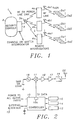
- FIG. 1 illustrates one embodiment of a random interval monitor system 1 (hereinafter also referred to as "RIMS") that is constructed in accordance with this invention.
- the system 1 comprises at least one console (hereinafter also referred to as a “master transceiver”) 3 and a plurality of transmitters (hereinafter also referred to as "tags", “transmit-only tags", or “TXs”) 5a1-5xx.
- the RIMS 1 also comprises at least one remote transceiver (hereinafter also referred to as a "transceiver”) 4a-4n, and at least one security station (confirmation device), which is, by example, a security console 2.
- the at least one remote transceiver 4a-4n is not utilized, and the security console 2 is replaced with another suitable device. These components may thus be considered as optional.
- each transceiver 3 has an antenna 3a; each of the remote transceivers 4a-4n has an antenna 4a1-4n1, respectively; and, referring to Figure 1, each tag 5a1-5xx has a respective antenna 22.
- RIMS 1 in the context of an application for detecting that a transmitter is being worn and, additionally, optionally, that a wearer at a work station is properly grounded and/or for tracking purposes to locate a wearer
- Apparatus embodiments of the preferred monitor system are illustrated in Figures 13-17.
- a wearable housing 68 having therein a transmitter tag 5a1 is attached to a wrist strap 70 and has protruding from its underside 72 a conventional pressure switch 74 which is depressed by contact with the wrist of a wearer.
- a motion detector 76 Within the housing 68 is a motion detector 76, generally termed a "motion/bump detector” and available from Fifth Dimension, Trenton, New Jersey, under catalog numbers 21680-701 or 21725-701.
- a ground connector comprising two wires 78, 80 leads from a ground connection sensor within the housing 68 for connection to a conventional ground site (not shown).
- a housing 68 attached to a wrist strap 70 has protruding from its underside 72 a conventional pressure switch 74 which is depressed by contact with the wrist of a wearer.
- the motion detector 76 within the housing 68 is the motion detector 76 as described above.
- Embedded in the strap 70 is an elongate conductive wire 82a that becomes a continuous circuit when the strap 70 is wrapped around a wrist and secured by a conductive standard clamp 84 for the embodiment shown in Figures 15 and 16, or that is a continuous circuit as a looped wire 82b as shown in Figure 17.
- Each sensor is in electrical communication with the transmitter tag 5a1 inside the housing 68.
- the devices of both embodiments monitor the presence or absence of pressure on the pressure switch 74, which is indicative of whether the tag is being worn, as well as the presence or absence of movement of the motion detector 76. If there is no pressure, or if there is no motion in a specified time interval, the tag 5a1 within the housing 68 will respond as described below.
- ground connection confirmation is accomplished by monitoring through the sensor of the presence of a small current sent through a resistor (e.g. 1 M ⁇ ) in the path to ground of the wire leads 78, 80.
- a resistor e.g. 1 M ⁇
- the monitoring system will monitor whether the tag is being worn and whether the housing 68 is connected to a ground site.
- the ground connection confirmation signal reaches the ground connection sensor for ultimate transfer as described above.
- Both the pressure sensor 74 and the motion detector 76 determine if the device is being worn since the pressure sensor 74 detects pressure from the body surface and the motion detector 76 detects movement of the body area of the wearer. If there is no pressure, if there is no motion in a specified time interval, and/or if there is no evidence of ground connection, this information is dispatched by the tag as an alarm. While the combination of these two sensors 74, 76 will produce a more reliable indication of whether the device is actually being worn since the information of each sensor is independently sent. Such independent transmissions permit a different weighting of the two sensor measurements and/or setting a different motion-time interval before an alarm status is reached. It is to be understood, however, that only a single sensor can be employed.
- the wearable device is especially suited for infants as in hospital nurseries.
- the embodiment includes a wrist strap 70 having, in addition to pressure and motion detectors 74, 76, a continuous closed circuit wire 82a, 82b imbedded within the strap.
- the strap 70 is tightly placed around the wrist of the infant and therefore is removable only by cutting or otherwise breaking the continuity of the strap. Such an action will also result in breaking the closed circuitry of the wire 82a, 82b to thereby generate a signal of such a break which is transmitted to the receiver as an alarm status.
- a plurality of receivers as described above can be strategically located throughout the hospital to thereby track infant movement and safety.
- the tag 5a1 is able to communicate effectively with at least one of the master transceiver 3 and one remote transceiver (e.g., remote transceiver 4a), as will be described below.
- Each of the tags 5a1-5xx operates in a first operating mode and a second operating mode.
- the first operating mode which, for the purposes of this description is also deemed to be a confidence mode, is the operating mode during which regular monitoring is performed and no alarm status is present.
- each individual tag 5a1-5xx independently communicates RF energy (e.g., confidence signals) over its antenna 22 to one of the remote transceivers (e.g., transceiver 4a) at random time intervals (to be described below).
- the tags 5a1-5xx employ Direct Sequence Spread Spectrum (DSSS), for transmitting signals.
- DSSS Direct Sequence Spread Spectrum
- Each of the confidence signals transmitted by an individual tag represents bits of information corresponding to the tag 5a1, and hence to the particular person wearing the tag 5a1.
- the information includes appropriate pressure and motion, as well as ground connection or strap-wire continuity, depending upon the embodiment involved.
- FIG. 2 illustrates a block diagram of a transmit-only tag (e.g., tag 5a1) constructed in accordance with a first and a second embodiment of this invention.
- a microprocessor controller 10 having a clock 10a emits control signals at random times that are determined by the clock 10a in a manner that will be described below.
- Each control signal emitted by the controller 10 is provided to a modulator 15, wherein the signal is mixed with a carrier signal generated by a local oscillator 18. Thereafter, the signal is amplified to an appropriate amplitude by an amplifier 16.
- the amplifier 17 shown in Figure 2 is employed in the second (alarm) embodiment of the invention, which will be discussed further below. Amplifier 17 does not necessarily need to be employed in the transmit-only tags of the first embodiment.
- each tag 5a1-5xx has an effective transmission range of, by example, at least 200 meters, and has a relatively low effective radiated power (ERP). Also, in a preferred embodiment of the invention, each tag 5a1-5xx transmits signals on a fixed frequency of, by example, 2.41GHz.
- antenna 22 for the individual tags 5a1-5xx is small in size and has an ability to radiate energy efficiently in a ground plane and/or in free space.
- the size of the antenna 22 is approximately 1 inch x 1 inch, with a thickness of 0.050 inches.
- the confidence signal is a relatively short duration (e.g., 10 to 100 ms) pulse signal.
- the generation of such short pulse signals allows each tag 5a1-5xx to use relatively small amounts of energy over time, and therefore preserves the energy of a power supply, such as a battery (not illustrated).
- the transmission times are produced truly randomly by employing "external" signals to "seed" a pseudo-random number generator (located within the controller 10) such as, by example, a binary shift register sequence generator, or another means known in the art for producing a pseudo-random sequence.
- a pseudo-random number generator located within the controller 10.
- a period e.g., 5 minutes, or 60 minutes
- initialization data e.g., a seed
- This period is deemed to be, for the purposes of this description, a first average time intervals.
- “external” signals are supplied to the controller 10 in response to, by example, detections of events (e.g., pressure, motion, ground connection, closed circuitry) made by at least one sensor (see below for a discussion of sensors 12 and 14.
- the controller 10 determines a temporal separation between, for example, two of the "external” signals supplied from the sensor, and uses this determined temporal spacing to "seed" the pseudo-random sequence generator.
- the controller 10 Based upon the first average time interval and the "seeding" of the pseudo-random number generator via the "external” signals, the controller 10 then emits control signals at random times, individual ones of which occur randomly during respective individual ones of sequentially occurring time intervals having durations equal to the first average time interval.
- the applicable tag e.g., tag 5a1 transmits confidence signals at random times, thereby enabling routine monitor checks (e.g., occurring approximately every 5 minutes, or every 60 minutes) of the person wearing the tag 5a1.
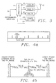
- Figure 4 illustrates an example of the sequentially occurring time intervals, during each of which occurs a random time slot designated as ton (time-on).
- the random times associated with the confidence mode are designated as "first random times”.
- Each remote transceiver 4a-4n functions as a communication relay to enable effective indirect communication between the master transceiver 3 and at least one tag 5a1-5xx for cases in which, by example, the master transceiver 3 is not located within the effective transmission range of a tag (e.g., tag 5a1).
- a remote transceiver e.g., remote transceiver 4a
- the remote transceiver 4a is positioned with respect to the tag 5a1 and master transceiver 3 in a manner such that it can relay signals from the tag 5a1 to the master transceiver 3.
- the remote transceiver 4a may be mounted near the entrance of the room where the wearer of the tag 5a1 is located, for example. This remote transceiver 4a may also serve to relay communications from other tags (e.g., tags 5a2-5ax) that are located within the same room, to the master transceiver 3.
- tags e.g., tags 5a2-5ax
- a single remote transceiver 4a may not be adequate to facilitate communications between the tag 5a1 and the master transceiver 3.
- additional remote transceivers 4a-4n may be employed in order to relay the transmissions.
- this description discusses the invention primarily in the context of an application wherein only a single remote transceiver (e.g., remote transceiver 4a) is employed to facilitate communication between at least one of the tags 5a1-5xx and the master transceiver 3. It also should be noted that, for the case in which a tag (e.g., tag 5a1) is able to communicate directly with a master transceiver 3, no remote transceivers 4a-4n need be employed in order to relay the communications.
- the remote transceivers 4a-4n intercommunicate with one another and/or with the master transceiver 3 via AC power lines.
- Figure 3 illustrates a power line link 50 for a remote transceiver 4a-4n (or a master transceiver 4).
- FIG. 3 illustrates a bock diagram of a transceiver which may function as a master receiver 3 or one of the remote transceivers 4a-4n, and which is constructed in accordance with various embodiments of the invention.
- An antenna 48 (which forms antenna 3a for a master receiver or antennas 4a1-4nn for the respective remote transceivers), is coupled to a direct Sequence Spread Spectrum Receiver (DSSS RX) block 42, a DSSS transmitter (DSSS TX) block 44, and an "ON-OFF" key transmitter (OOK TX) block 46.
- the DSSS RX block 42 is employed in all embodiments of the invention for receiving signals from tags 5a1-5nn, other remote transceivers 4a-4n, and the master transceiver 3.
- the DSSS RX block 42 employs a known type of Direct Sequence Spread Spectrum technique for receiving signals.
- a signal is received by the transceiver via antenna 48, the signal is provided to the DSSS RX block 42 wherein it is decoded and checked for errors. Signals that are received with errors from tags 5a1-5xx are ignored. Signals received by a remote transceiver 4a from the master transceiver 3 are error-checked. If the signal is received without error, the remote transceiver 4a responds back to the master receiver 3 with a verification signal. If there is no verification signal received by the master transceiver 3, the master transceiver transmits again, with a random delay determined by the processor 40 of the master transceiver 3, which handles appropriate protocol functions. It should be noted that a situation in which the master transceiver 3 transmits signals to remote transceivers 4a-4n is addressed below with respect to an embodiment of the invention employing data reduction.
- the DSSS TX block 44 is employed to transmit, in response to a signal received from the processor 40, signals using a DSSS technique. Signals provided from the DSSS TX block 44 are transmitted via the antenna 48 to other ones of the remote transceivers 4a-4n, or to the master transceiver 3, as is required by the application of interest.
- the DSSS TX block 44 is primarily employed in the first embodiment of the invention, and in the second embodiment of the invention which will be described below.
- the OOK TX block 46 is employed (in lieu of the DSSS TX block 44) in an embodiment of the invention employing receive/transmit(RX/TX) tags, which also will be described below. In the RX/TX embodiment, the OOK TX block 46 is used for transmitting signals to the RX/TX tags.
- the antenna 48 can be, for example, an omni-directional antenna with low gain, or a high gain, directional antenna (which will increase transmission range approximately 2-3 times) where appropriate. Also, similar to the tags 5a1-5xx, each transceiver has a user-interface 54 for programming information into the transceiver.
- power line link block 50 is employed instead of the DSSS TX block 44.
- an interface line 52 which is used in a master transceiver 3 to interface with the security console 2, or to a pager system.
- a signal is received by the master receiver 3, it is forwarded to the security console 2 wherein the signal is recognized as corresponding to a portion of the information stored within the security console 2. More particularly, information stored within the security console 2 corresponds to the bits of information transmitted by each tag 5a1-5xx. As such, when the security console 2 receives a confidence signal from one of the tags (e.g., tag 5a1) of a particular wearer, and thereafter recognizes the received information as corresponding to information stored within the security console 2, it is confirmed that the wearer is properly active.
- the security console 2 receives a confidence signal from one of the tags (e.g., tag 5a1) of a particular wearer, and thereafter recognizes the received information as corresponding to information stored within the security console 2, it is confirmed that the wearer is properly active.
- the second mode in which the tags 5a1-5xx operate is deemed, for the purposes of this description, to be an "alarm mode".
- This operating mode is useful for tracking the movement of a wearer or for identifying an occurrence of a specified event, such as, for example, improper removal of a tag, a non-grounded condition, etc.
- the alarm mode is implemented in a manner that is made apparent by the following example. Referring to Figure 2, motion sensor 12 associated with a tag (e.g., tag 5a1) senses the lack of movement of an arm of a person wearing the tag. The sensor 12 supplies information representing the occurrence of the specified event to the controller 10 which, in response, emits control signals at second random time intervals. The second random time intervals are based upon a second average time interval.
- the second average time interval is predetermined by, for example, a user entering information into the controller 10 via the user interface 13 for specifying an approximate average frequency (e.g., every 1 second, or every 15 seconds) at which it is desired to be notified of alarm signals once the specified event has been detected.
- Each control signal is mixed at modulator 15 with a carrier signal generated by local oscillator 18 and amplified by amplifier 16 in the same manner as described above for the confidence mode.
- the signal is transmitted as an alarm signal over antenna 22 to one of the remote transceivers (e.g., remote transceiver 4a). Thereafter the alarm signal is relayed to the master transceiver 3, in the same manner as described above for the confidence mode.
- the master transceiver 3 then supplies the alarm signal to the security console wherein it is determined that, based upon the frequency of reception of the alarm signals with respect to that of the confidence signals, the specified event (e.g., non-movement) has occurred.
- the second operating mode may also be invoked by the pressure switch monitoring sensor 14 associated with tag 5a1 sensing that a pressure switch is open, or by any other type of sensor interfaced with the tag 5a1 sensing an occurrence of a specified event. for the purposes of this invention, tags 5a1-5xx which are operating in the alarm mode are deemed to be "active tags".
- the RIMS 1 performs tracking of the wearers.
- the technique by which the RIMS 1 performs tracking may be any technique known in the art for determining relative locations based upon power measurements of signals received from transmitters located with the respective wearers.
- the technique can be performed at, for example, the individual remote transceivers 4a-4nm, the master transceiver 3, and/or the security console 2.
- a first signal received by the security console 2 is measured to determine the received signal's strength.
- the determined signal strength is stored within the security console 2.
- the security console 2 measures the signal strength of this second signal.
- a displacement of the tag and its associated wearer occurring between the time when the first signal was transmitted and the time when the second signal was transmitted can be determined.
- a calculation can then be made to determine the location of the wearer.
- the same process occurs for subsequently received signals.
- the process can also be carried out by comparing measured signal strengths of signals received from a tag with a reference signal strength transmitted by the tag when at its assigned location.
- the remote transceivers 4a-4n autonomously perform data reduction by identifying what information needs to be communicated to the master receiver 3 (e.g., what has changed in the monitor or alarm status). This information is provided to the master transceiver 3 in response to a command received from the master transceiver 3 interrogating the remote transceivers 4a-4n to transmit monitor and alarm status signals. In this manner, as opposed to providing a complete list of all current transmitters, the remote transceivers 4a-4n simply provide information indicating, by example, changes in alarm or monitor status. This protocol is applicable in applications using the transmit-only tags and the remote interrogators 4a-4n for facilitating communication (e.g., limited data loading) with the master receiver 3.
- a change in status may be identified by the remote transceiver recognizing that a signal has not been received from a particular tag within a first predetermined time period.
- an internal clock (not illustrated) within the remote transceiver 4a begins to run. If the time kept by the clock then exceeds the first predetermined time value stored within the remote transceiver 4a, a change in status is recognized by the remote transceiver 4a.
- the change in status may indicate, for example, that a wearer of a tag 5a1 has been moved out of range of the remote transceiver 4a.
- the remote transceiver 4a stores information which indicates this change in status and which identifies the particular tag (and its wearer) from which the signal was originally transmitted.
- a remote transceiver can recognize that two signals received from a particular one of the tags have been received by the remote transceiver within a second predetermined time period (i.e., indicating the alarm mode). Also, as described above, the remote transceiver may measure signal strengths of received signals in order to determine whether a wearer has left an assigned or reference location.
- the master transceiver 3 transmits commands to the remote transceivers 4a-4n in order to interrogate them for sending back status signals. This may occur at, for example, predetermined time intervals.
- a command signal transmitted by the master transceiver 3 is received by a remote transceiver (e.g., remote transceiver 4a)
- the remote transceiver 4a responds by transmitting stored information which indicates any changes in status and which identifies particular tags (wearers) associated with those changes in status identified by the remote transceiver 4a since, by example, a last command was received by the master transceiver 3.
- the information is received by the master transceiver 3 and is then supplied to the security console 2 for notifying, by example, a user of the changes in status affecting the particular tag (wearer) identified by the information.
- the remote interrogator 4a responds to commands received from the master transceiver 3 by providing the information indicating changes in status that have been identified and stored by the remote interrogator 4a over a predetermined time period.
- the manner in which signals are transmitted from each tag 5a1-5xx can be set to minimize the possibility that signals transmitted by more than one tag 5a1-5xx will be received simultaneously by the master transceiver 3, for example, this may be accomplished by operating the user interface or by using detections made by a sensor (e.g., sensor 12 and/or 14) of each tag 5a1-5xx. Also by example, this may be accomplished by varying the random timing variations (frequencies) of the clock 10a associated with each tag 5a1-5xx. As such, the probability that more than one tag 5a1-5xx will transmit simultaneously receive signals from more than one tag 5a1-5xx, is minimized. This can be further understood in consideration of the following probability equations.
- P tx ton ton+toff
- Ptx represents the probability that a particular tag (e.g., tag 5a1) is transmitting a signal
- ton the duration of the transmission of a randomly occurring signal
- toff represents an average time interval between random transmissions.
- P ntx toff ton+toff
- ton and toff represent the same information as defined above.
- P tx represents the probability that an individual transmitting tag (e.g., tag 5a1) is the only one of the tags 5a1-5xx that is transmitting a signal at a particular time ton and toff have the same meanings as described above; and represents the total number of tags (e.g., tags 5a2-5ax), not including a transmitting tag of interest (e.g., tag 5a1), that may be transmitting a signal at the same time as the transmitting tag 5a1.
- n , ton , and toff have the same meanings as described above, and m represents the number of confidence signal transmissions made by a transmitting tag of interest (e.g., tag 5a1).
- Figure 5 illustrates a graph representing probabilities that no tags 5a1-5xx are transmitting alarm signals at any one time, for a case wherein there are various numbers (0 to 1000) of tags 5a1-5xx randomly transmitting a 12 bit packet, 1 kbps information signals based upon a second average time interval of 15 second duration.
- Figure 6 illustrates a graph representing probabilities that a particular one tag (e.g., tag 5a1) of 500 tags 5a1-5xx will successfully communicate 12 bit packet, 1 kbps alarm signals with the master transceiver 3 per each of 10 successive random transmissions occurring based upon a second average time interval of 15 second duration.
- a particular one tag e.g., tag 5a1
- tag 5a1-5xx will successfully communicate 12 bit packet, 1 kbps alarm signals with the master transceiver 3 per each of 10 successive random transmissions occurring based upon a second average time interval of 15 second duration.
- Figure 7 illustrates a graph representing probabilities that no activated ones of various numbers (0 to 1000) of tags 5a1-5xx are transmitting alarm signals at any one time, for a case wherein the tags 5a1-5xx are randomly transmitting 12 bit packet, 1 kbps information signals based upon a second average time interval of 1 second duration.
- Figure 8 illustrates a graph representing probabilities that a particular one tag (e.g., tag 5a1) of 50 transmitting tags 5a1-5xx will successfully communicate 12 bit packet, 1 kbps alarm signals with the master transceiver 3 per each of 10 successive transmissions, wherein each tag 5a1-5xx randomly transmits alarm signals based upon a second average time interval of 1 second duration.
- tag 5a1 e.g., tag 5a1
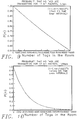
- Figure 9 illustrates a graph representing probabilities that no tags 5a1-5xx are transmitting information signals at any one time while the tags 5a1-5xx are operating in the confidence mode, wherein there are various numbers (0 to 10000) of tags 5a1-5xx randomly transmitting 17 bit packet, 1 kbps information signals of 17 millisecond pulse duration, based upon a first average time interval of 5 minute duration.
- Figure 10 illustrates a graph representing probabilities that no tags 5a1-5xx are transmitting information signals at any one time, during the confidence mode of operation, for various numbers (0 to 10000) of tags 5a1-5xx that are randomly transmitting 17 bit packet, 120 bps information signals of 141 millisecond pulse duration, based upon a first average time interval of 5 minutes.
- Figure 11 illustrates a graph representing probabilities that a particular one tag (e.g., tag 5a1) of 1000 tags 5a1-5xx will successfully communicate 17 bit packet, 1 kbps, and 17 millisecond pulse duration information signals with the master transceiver 3 per each of 10 successive random transmissions occurring based upon a first average time interval of 5 minutes.
- a particular one tag e.g., tag 5a1
- tag 5a1-5xx will successfully communicate 17 bit packet, 1 kbps, and 17 millisecond pulse duration information signals with the master transceiver 3 per each of 10 successive random transmissions occurring based upon a first average time interval of 5 minutes.
- Figure 12 illustrates a graph representing probabilities that a particular one tag (e.g., tag 5a1) of 1000 tags 5a1-5xx will successfully communicate 141 millisecond pulse duration information signals with the master transceiver 3 per each of 10 successive random transmissions occurring based upon a first average time interval of 5 minutes.
- a particular one tag e.g., tag 5a1
- tag 5a1-5xx will successfully communicate 141 millisecond pulse duration information signals with the master transceiver 3 per each of 10 successive random transmissions occurring based upon a first average time interval of 5 minutes.
- this further embodiment is referred to as a "Transmit-Then-Receive" (TTR) protocol embodiment wherein individual tags 5a1-5xx transmit signals at intervals to one of the master transceiver 3 or a remote interrogator (e.g., remote interrogator 4a) in order to perform monitoring of persons wearing the tags, in the same manner as was described above.
- TTR Transmit-Then-Receive
- each transmission is followed by a predetermined waiting period, during which the tag operates in a receive mode, instead of a transmit mode, for a predetermined time interval.
- each of the master transceiver 3 and the remote transceivers 4a-4n comprise (in lieu of the DSSS TX block 44) the OOK TX block 46 which functions as described below.
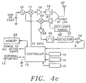
- FIG. 4c illustrates an RX/TX tag constructed in accordance with a preferred embodiment of this invention.
- the RX/TX tag is similar to the transmit-only tag of the first embodiment of the invention in that it comprises a local oscillator 18, a modulator 11, an amplifier 16, a filter 19, a microprocessor controller 10, a pressure switch monitor sensor 14, a motion monitor sensor 12, a ground connection sensor 15, an antenna 22, and an external user-interface 13. These elements function in a similar manner to the same elements of the transmit-only tag, although the controller 10 performs additional functions over that for the transmit-only tags.
- the RX/TX tag also comprises a larger memory (e.g., 1 to 100 kilobyte) 60 than the transmit-only tag (whose memory is not illustrated in Figure 2) and circuitry, namely an OOK receiver circuit, enabling it to receive signals.
- the controller 10 controls the RX/TX tag to change its operating mode from the transmit mode to the receive mode for a time interval that is predetermined by, for example, information entered previously into controller 10 via the user-interface 13.
- the time interval is preferably a short time interval.
- an amplifier 64 has an input that is coupled to antenna 22 such that when the RX/TX tag is in a receive mode and a signal is received by the antenna 22, the signal is amplified to an appropriate level by amplifier 64.
- the amplifier 64 is tunable by an off-chip tuning block 66.
- a mixer 62 thereafter mixes the amplified signal with an output of local oscillator 18, whereafter the signal is amplified by amplifier 68 and thence filtered by a filter 70.
- a detector circuit 72 detects an output of the filter 70 and thereafter provides a signal to a logic block 74 which is, by example, a comparator.
- the comparator 74 determines whether a signal received from the detector 72 is of a sufficient magnitude (e.g., above a noise level) to indicate a signal is present.
- the controller 10 controls the RX/TX tag to change its operating mode from the transmit mode to the receive mode.
- the remote transceiver 4a receives the signal over antenna 48, which then provides the received signal to DSSS RX block 42, wherein appropriate receiving functions are performed to the signal ( Figure 3). After the signal passes through the DSSS RX block 42, the signal is provided to the processor 40.
- the processor 40 measures the frequency of the signal, which frequency was set originally at the transmitting RX/TX tag 5a1. This frequency measurement process occurs as a first step in the spread spectrum signal receive operation, and as such does not increase the complexity of the system. Following the frequency determination, the processor 40 controls the OOK TX block 46 to "cycle-on" so as to transmit a return data signal to the RX/TX tag 5a1 at a frequency set to be substantially the same as the measured frequency.
- the return data signal may carry information specifying, by example, a new first and/or second average time interval for the Rx/TX tag 5a1, an identification number, or that the controller 10 of the RX/TX tag 5a1 shall cease the RX/TX tag 5a1 from making further transmissions.
- the processor 40 controls the OOK TX block 46 to turn off.
- This frequency adjustment scheme allows for improved system characteristics such as, by example, a relatively simple, inexpensive tag Local Oscillator (LO), the minimization of tag IF bandwidth requirements (thereby maximizing sensitivity and operational range), and an inexpensive OOK style receiver.
- LO Local Oscillator
- the signal traverses the receiving circuitry in the manner described above, ultimately being provided to controller 10. Thereafter, the controller 10 changes the operating mode from the receive mode to the transmit mode, and performs an error check to determine whether the received signal carries error-free data. If it is determined that the return signal does carry error-free data, the tag may indicate same by transmitting an acknowledgement signal back to the remote interrogator 4a.
- the RX/TX tag 5a1 may transmit a signal to the remote transceiver 4a requesting a re-transmission, whereafter the remote transceiver 4a re-transmits the signal until the TX/RX tag 5a1 controller 10 determines that the signal has been received without error. If the RX/TX controller 10 continually finds an error in the signals received from remote interrogator 4a, and the Rx/Tx tag 5a1 transmits a re-transmission request signal to the remote transceiver 4a a predetermined number of times, the remote transceiver 4a transmits a signal back to the master transceiver 3 indicating failure.
- the master transceiver 3 can function in the same manner as described above for the remote interrogator 4a.
- the application is described in the context in which the remote interrogator 4a sends a response signal to the RX/TX tag 5a1, in some applications it may not be necessary to send a response signal.
- data that is received without error need not be acknowledged back to the remote transceiver 4a.
- the RX/TX tags 5a1-txx operate at a fixed frequency.
- Figure 4b illustrates a preferable approximate frequency (ie.., 2.414 GHz) of an Rx tag local oscillator.
- Figure 4b also shows possible receive band schemes for the RX/TX tag embodiment of the invention, including an ISM band for low power receive applications, and a higher-frequency licensed band for higher power applications.
- the tags transmit for short intervals, pause, and then change to a receive mode for a short interval, the tags operate in an energy-efficient manner.
Claims (28)
- Un procédé pour surveiller des personnes individuelles parmi une multiplicité de personnes, comprenant les étapes suivantes:on émet des signaux d'information à des instants aléatoires à partir d'étiquettes individuelles d'une multiplicité d'étiquettes, vers au moins un émetteur-récepteur maítre, chaque étiquette individuelle de la multiplicité d'étiquettes devant être portée par une personne respective, les signaux d'information émis par les étiquettes individuelles correspondant au fait que l'étiquette est en cours d'utilisation ou non, et une probabilité que l'une individuelle de la multiplicité d'étiquettes émette un signal d'information pendant une période au cours de laquelle aucune des autres de la multiplicité d'étiquettes n'émet des signaux d'infotmation étant représentée par Ptx, avec:en réponse au fait que l'au moins un émetteur-récepteur maítre reçoit un signal d'information, on fournit le signal d'information à un dispositif de confirmation associé; etdans le dispositif de confirmation, en réponse à la réception d'un signal d'information provenant de l'émetteur-récepteur maítre, on confirme que la personne correspondant à l'étiquette générant le signal d'information est prise en compte.
- Un procédé selon la revendication 1, dans lequel les instants aléatoires apparaissent en fonction d'un premier intervalle de temps spécifié.
- Un procédé selon la revendication 2, dans lequel les instants aléatoires apparaissent également en fonction d'une cadence à laquelle des événements spécifiés sont détectés par au moins un capteur.
- Un procédé selon la revendication 1, dans lequel l'étape d'émission est effectuée de façon à émettre les signaux d'information à partir d'étiquettes individuelles vers l'un au moins de l'au moins un émetteur-récepteur maítre et au moins un émetteur-récepteur distant.
- Un procédé selon la revendication 4, dans lequel pour un cas dans lequel les signaux d'information sont émis vers l'au moins un émetteur-récepteur distant, l'émetteur-récepteur distant reçoit des signaux d'information provenant de l'une au moins de la multiplicité d'étiquettes et, en réponse à la réception de chacun des signaux d'information, il relaie le signal vers l'émetteur-récepteur maítre.
- Un procédé selon la revendication 4, dans lequel l'émetteur-récepteur distant reçoit des signaux d'information provenant de l'au moins une étiquette parmi la multiplicité d'étiquettes sous la dépendance, au moins en partie, d'une position de l'émetteur-récepteur distant par rapport à celle de l'au moins une étiquette de la multiplicité d'étiquettes.
- Un procédé selon la revendication 4, dans lequel le fait que les étiquettes individuelles de la multiplicité d'étiquettes émettent des signaux d'information vers l'émetteur-récepteur maítre ou vers l'émetteur-récepteur distant dépend, au moins en partie, des positions des étiquettes individuelles de la multiplicité d'étiquettes par rapport à des positions de l'émetteur-récepteur maítre et de l'émetteur-récepteur distant.
- Un procédé selon la revendication 1, dans lequel des instants individuels parmi les instants aléatoires apparaissent de façon aléatoire pendant des intervalles de temps individuels respectifs parmi des intervalles de temps apparaissant séquentiellement.
- Un procédé selon la revendication 1, comprenant en outre l'étape suivante:on détecte une apparition ou une non-apparition d'un événement spécifié affectant n'importe lesquelles des personnes portant les étiquettes, et en réponse à ceci, l'étiquette devant être portée par une personne affectée émet des signaux d'information basés sur des instants aléatoires apparaissant en fonction d'un second intervalle de temps spécifié.
- Un procédé selon la revendication 9, dans lequel au moins un premier et un second des signaux d'information sont émis de façon à être séparés dans le temps en fonction du second intervalle de temps spécifié, pour indiquer ainsi la détection de l'événement spécifié se produisant pour la personne affectée, et dans lequel l'étape de confirmation comprend en outre l'étape suivante:on détermine que le premier et le second des signaux d'information ont été reçus et sont séparés dans le temps en fonction du second intervalle de temps spécifié, et on reconnaít ensuite la détection de l'événement spécifié se produisant pour la personne affectée.
- Un procédé selon la revendication 10, dans lequel l'événement spécifié ou son absence est l'un au moins des suivants: une pression de contact sur l'étiquette, un mouvement, une connexion à la terre et une fermeture de circuit
- Un procédé selon la revendication 10, dans lequel des instants individuels parmi les instants aléatoires apparaissent de façon aléatoire pendant des intervalles de temps individuels respectifs parmi des intervalles de temps apparaissant séquentiellement.
- Un procédé selon la revendication 4, comprenant en outre l'étape suivante:dans l'un au moins des émetteurs-récepteurs maítres, de l'au moins un émetteur-récepteur distant et du dispositif de confirmation, en réponse à la réception d'un signal d'information émis à l'origine par l'une individuelle des étiquettes, on mesure un niveau de signal du signal d'information reçu pour obtenir un niveau de signal mesuré du signal d'iaformation reçu; etsur la base d'une différence entre le niveau du signal mesuré du signal d'information reçu et un niveau de signal de référence, on détermine l'un au moins d'un déplacement et d'un emplacement d'une personne portant l'étiquette.
- Un procédé selon la revendication 1, dans lequel l'étape d'émission est effectuée en utilisant une technique de spectre étalé à séquence directe (ou DSSS pour "Direct Sequence Spread Spectrum").
- Un procédé selon la revendication 5, dans lequel l'étape d'émission est effectuée en utilisant une technique de spectre étalé à séquence directe (ou DSSS pour "Direct Séquence Spread Spectrum").
- Un procédé selon la revendication 1, dans lequel chaque étiquette individuelle de la multiplicité d'étiquettes émet des signaux d'information indépendamment des autres de la multiplicité d'étiquettes, ce qui limite une probabilité que l'émetteur-récepteur maítre reçoive simultanément plus d'un signal d'information.
- Un procédé selon la revendication 1, comprenant en outre les étapes suivantes:à des étiquettes individuelles de la multiplicité d'étiquettes:en réponse à l'émission d'un premier des signaux d'information, on commute vers un mode de fonctionnement de réception pendant un intervalle de temps prédéterminé; eten réponse à une expiration de l'intervalle de temps prédéterminé, on commute vers un mode de fonctionnement d'émission par lequel un second des signaux d'information est émis.
- Un procédé selon la revendication 17, dans lequel en réponse au fait que l'au moins un récepteur maítre reçoit un premier signal d'information provenant de l'une quelconque de la multiplicité d'étiquettes, le récepteur maítre accomplit les étapes suivantes:il détermine une fréquence du premier signal d'information reçu; etil émet un signal de réponse vers l'étiquette à partir de laquelle le premier signal d'information a été reçu, de façon que l'étiquette reçoive le signal de réponse pendant l'intervalle de temps prédéterminé.
- Un procédé selon la revendication 18, dans lequel en réponse à la réception du signal de réponse, l'étiquette effectue un contrôle d'erreur du signal de réponse, après quoi l'étiquette émet vers le récepteur maítre un signal indiquant si une erreur a été détectée ou non dans le signal de réponse.
- Un système de surveillance ayant un dispositif d'auto-surveillance pour vérifier l'usage, le système comprenant:un boítier pouvant être porté par une personne;un émetteur disposé à l'intérieur du boítier,un capteur de pression en communication électrique avec l'émetteur et disposé à l'intérieur du boítier de façon à s'étendre à partir de celui-ci et à être en contact avec la personne lorsque le boítier est porté, pour ainsi imposer une pression sur le capteur et créer un signal électrique, ce capteur de pression transmettant à l'émetteur un premier signal électrique représentant la présence ou l'absence de la pression;un capteur de mouvement en communication électrique avec l'émetteur et disposé à l'intérieur du boítier pour détecter son mouvement, le capteur de mouvement transmettant à l'émetteur un second signal électrique représentant la présence ou l'absence du mouvement;un capteur de connexion de terre en communication électrique avec l'émetteur et disposé à l'intérieur du boítier, ce capteur de connexion de terre ayant un connecteur de terre partant de lui et pouvant être fixé à un site de terre, ce site de terre ayant un signal de confirmation de connexion de terre pouvant être transféré vers le capteur de connexion de terre par l'intermédiaire du connecteur de terre, pour détecter une connexion de terre du dispositif et transmettre à l'émetteur un troisième signal électrique représentant la présence ou l'absence de la connexion de terre; etau moins un récepteur capable de recevoir des émissions d'information de pression, de mouvement et de connexion de terre émises par l'émetteur.
- Un système de surveillance selon la revendication 20, dans lequel le boítier pouvant être porté par une personne est adapté pour être porté sur un poignet.
- Un système de surveillance selon la revendication 21, dans lequel le boítier peut être fixé à la personne avec un bracelet.
- Un système de surveillance selon la revendication 20, dans lequel une multiplicité de récepteurs sont respectivement situés à une multiplicité de sites.
- Un système de surveillance selon la revendication 20, dans lequel le connecteur de terre comprend deux fils disposés entre le site de terre et le capteur de connexion de terre.
- Un système de surveillance selon la revendication 24, dans lequel une résistance est incorporée à l'intérieur du connecteur de terre et le signal de confirmation de connexion de terre est la résistance qu'elle oppose à un signal électrique transféré à partir du site de terre à travers le connecteur de terra.
- Un système de surveillance selon la revendication 20, dans lequel le capteur de pression comprend un interrupteur actionné par la pression ayant un circuit fermé lorsqu'il est en contact avec la personne.
- Un système de surveillance selon la revendication 20, dans lequel le capteur de mouvement comprend un interrupteur qui est dans une configuration de circuit fermé au repos et est ouvert au cours de brefs intervalles pendant le mouvement.
- Un dispositif de surveillance personnel ayant un dispositif d'auto-surveillance pour vérifier l'usage, le dispositif de surveillance comprenant:un boítier pouvant être porté par une personne;un émetteur disposé à l'intérieur du boítier,un capteur de pression en communication électrique avec l'émetteur et disposé à l'intérieur du boítier de façon à s'étendre à partir de celui-ci et à être en contact avec la personne lorsque le boítier est porté, pour ainsi imposer une pression au capteur et créer un signal électrique, ce capteur de pression transmettant à l'émetteur un premier signal électrique représentant la présence ou l'absence de la pression;un capteur de mouvement en communication électrique avec l'émetteur et disposé à l'intérieur du boítier pour détecter le mouvement de celui-ci, ce capteur de mouvement transmettant à l'émetteur un second signal électrique représentant la présence ou l'absence du mouvement; etun capteur de connexion de terre en communication électrique avec l'émetteur et disposé à l'intérieur du boítier, ce capteur de connexion de terre ayant un connecteur de terre s'étendant à partir de lui et pouvant être fixé à un site de terre, ce site de terre ayant un signal de confirmation de connexion de terre pouvant être transféré vers le capteur de connexion de terre par l'intermédiaire du connecteur de terre, pour détecter une connexion de terre du dispositif et transmettre à l'émetteur un troisième signal électrique représentant la présence ou l'absence de la connexion de terre.
Applications Claiming Priority (3)
| Application Number | Priority Date | Filing Date | Title |
|---|---|---|---|
| US08/663,340 US5745037A (en) | 1996-06-13 | 1996-06-13 | Personnel monitoring tag |
| US663340 | 1996-06-13 | ||
| PCT/US1997/002708 WO1997048081A1 (fr) | 1996-06-13 | 1997-02-21 | Systeme de surveillance personnelle a intervalle aleatoire |
Publications (3)
| Publication Number | Publication Date |
|---|---|
| EP0904582A1 EP0904582A1 (fr) | 1999-03-31 |
| EP0904582A4 EP0904582A4 (fr) | 2001-03-21 |
| EP0904582B1 true EP0904582B1 (fr) | 2003-05-02 |
Family
ID=24661406
Family Applications (1)
| Application Number | Title | Priority Date | Filing Date |
|---|---|---|---|
| EP97907746A Expired - Lifetime EP0904582B1 (fr) | 1996-06-13 | 1997-02-21 | Etiquette de surveillance personnelle |
Country Status (4)
| Country | Link |
|---|---|
| US (1) | US5745037A (fr) |
| EP (1) | EP0904582B1 (fr) |
| DE (1) | DE69721528T2 (fr) |
| WO (1) | WO1997048081A1 (fr) |
Families Citing this family (136)
| Publication number | Priority date | Publication date | Assignee | Title |
|---|---|---|---|---|
| US5539775A (en) | 1993-03-17 | 1996-07-23 | Micron Technology, Inc. | Modulated spread spectrum in RF identification systems method |
| US8280682B2 (en) * | 2000-12-15 | 2012-10-02 | Tvipr, Llc | Device for monitoring movement of shipped goods |
| US6266623B1 (en) | 1994-11-21 | 2001-07-24 | Phatrat Technology, Inc. | Sport monitoring apparatus for determining loft time, speed, power absorbed and other factors such as height |
| US7386401B2 (en) | 1994-11-21 | 2008-06-10 | Phatrat Technology, Llc | Helmet that reports impact information, and associated methods |
| US6128549A (en) * | 1996-06-21 | 2000-10-03 | Symbol Technologies, Inc. | RF interrogatable processing system |
| US6570487B1 (en) | 1997-01-24 | 2003-05-27 | Axcess Inc. | Distributed tag reader system and method |
| US6034603A (en) * | 1997-01-24 | 2000-03-07 | Axcess, Inc. | Radio tag system and method with improved tag interference avoidance |
| US6148195A (en) * | 1997-02-18 | 2000-11-14 | Itt Manufacturing Enterprises, Inc. | Phase agile antenna for use in position determination |
| US6148219A (en) * | 1997-02-18 | 2000-11-14 | Itt Manufacturing Enterprises, Inc. | Positioning system for CDMA/PCS communications system |
| US6035260A (en) * | 1997-04-23 | 2000-03-07 | Northrop Grumman Corporation | Wrist strap integrity check circuitry |
| US6393045B1 (en) * | 1997-09-26 | 2002-05-21 | Wherenet Corp. | Spread spectrum baseband modulation of magnetic fields for communications and proximity sensing |
| US5982285A (en) * | 1998-05-14 | 1999-11-09 | Bueche; Kenneth M. | Compliance monitoring system |
| US6420961B1 (en) * | 1998-05-14 | 2002-07-16 | Micron Technology, Inc. | Wireless communication systems, interfacing devices, communication methods, methods of interfacing with an interrogator, and methods of operating an interrogator |
| CA2246022A1 (fr) * | 1998-08-28 | 2000-02-28 | Strategic Technologies Inc. | Systeme electronique de surveillance d'heure de rentree |
| US6043746A (en) * | 1999-02-17 | 2000-03-28 | Microchip Technology Incorporated | Radio frequency identification (RFID) security tag for merchandise and method therefor |
| US6294953B1 (en) | 1999-02-26 | 2001-09-25 | Axcess, Inc. | High sensitivity demodulator for a radio tag and method |
| US6356764B1 (en) * | 1999-03-09 | 2002-03-12 | Micron Technology, Inc. | Wireless communication systems, interrogators and methods of communicating within a wireless communication system |
| FR2791452B1 (fr) * | 1999-03-22 | 2002-01-18 | Catherine Claude Mari Coutelou | Dispositif de surveillance d'un groupe d'individus par radio-frequence |
| US6262660B1 (en) * | 1999-04-30 | 2001-07-17 | Erica Marmon Segale | Child proximity transmitter |
| US6211790B1 (en) | 1999-05-19 | 2001-04-03 | Elpas North America, Inc. | Infant and parent matching and security system and method of matching infant and parent |
| US7005985B1 (en) | 1999-07-20 | 2006-02-28 | Axcess, Inc. | Radio frequency identification system and method |
| US6297734B1 (en) | 1999-09-23 | 2001-10-02 | Northrop Grumman Corporation | Randomization of transmit time |
| US6844816B1 (en) | 1999-10-05 | 2005-01-18 | Bi Incorporated | Authentication techniques in a monitoring system |
| US7286158B1 (en) | 1999-12-22 | 2007-10-23 | Axcess International Inc. | Method and system for providing integrated remote monitoring services |
| US6650241B2 (en) * | 1999-12-23 | 2003-11-18 | Harold G. Osborne | Child safety device |
| US6859485B2 (en) * | 2000-03-07 | 2005-02-22 | Wherenet Corporation | Geolocation system with controllable tags enabled by wireless communications to the tags |
| US7768546B1 (en) | 2000-05-12 | 2010-08-03 | Axcess International, Inc. | Integrated security system and method |
| WO2002033620A1 (fr) * | 2000-10-16 | 2002-04-25 | Calaman Gregory A | Systeme de securite personnelle reposant sur la detection d'evenements |
| US6535129B1 (en) | 2000-11-17 | 2003-03-18 | Moore North America, Inc. | Chain of custody business form with automated wireless data logging feature |
| US6684289B1 (en) * | 2000-11-22 | 2004-01-27 | Sandisk Corporation | Techniques for operating non-volatile memory systems with data sectors having different sizes than the sizes of the pages and/or blocks of the memory |
| US7253717B2 (en) * | 2000-11-29 | 2007-08-07 | Mobile Technics Llc | Method and system for communicating with and tracking RFID transponders |
| US7171331B2 (en) | 2001-12-17 | 2007-01-30 | Phatrat Technology, Llc | Shoes employing monitoring devices, and associated methods |
| US6466126B2 (en) * | 2001-01-19 | 2002-10-15 | Motorola, Inc. | Portable data device efficiently utilizing its available power and method thereof |
| US6448895B1 (en) * | 2001-02-28 | 2002-09-10 | Koninklijke Philips Electronics N.V. | Kidnap alarm with acceleration sensor |
| CA2438172C (fr) * | 2001-03-12 | 2007-01-16 | Eureka Technology Partners, Llc | Systeme de localisation d'objets |
| AUPR399601A0 (en) * | 2001-03-27 | 2001-04-26 | Silverbrook Research Pty. Ltd. | An apparatus and method(ART108) |
| US7242306B2 (en) | 2001-05-08 | 2007-07-10 | Hill-Rom Services, Inc. | Article locating and tracking apparatus and method |
| EP1386285A1 (fr) | 2001-05-08 | 2004-02-04 | Hill-Rom Services, Inc. | Systeme de suivi et de localisation d'un article |
| US6972683B2 (en) * | 2001-07-20 | 2005-12-06 | Hill-Rom Services, Inc. | Badge for a locating and tracking system |
| JP4039039B2 (ja) * | 2001-11-08 | 2008-01-30 | ソニー株式会社 | 個人認証装置 |
| US7023356B2 (en) | 2001-11-26 | 2006-04-04 | Aero-Vision Technologies, Inc. | System and method for monitoring individuals and objects associated with wireless identification tags |
| US6972682B2 (en) | 2002-01-18 | 2005-12-06 | Georgia Tech Research Corporation | Monitoring and tracking of assets by utilizing wireless communications |
| FR2835983B1 (fr) * | 2002-02-13 | 2010-10-22 | Jean Marc Baggio | Systeme hertzien d'alerte de proximite et d'analyse ou de gestion des positions et des deplacements relatifs |
| US20030206100A1 (en) * | 2002-05-04 | 2003-11-06 | Lawrence Richman | Method and protocol for real time security system |
| US6639516B1 (en) | 2002-05-14 | 2003-10-28 | Shaun Michael Copley | Personal tracking device |
| US7015817B2 (en) * | 2002-05-14 | 2006-03-21 | Shuan Michael Copley | Personal tracking device |
| US7002472B2 (en) * | 2002-09-04 | 2006-02-21 | Northrop Grumman Corporation | Smart and secure container |
| CA2495686A1 (fr) * | 2002-09-27 | 2004-04-15 | Hill-Rom Services, Inc. | Systeme de communication, de regulation, de suivi et de controle universel pour un etablissement de soins de sante |
| US6917290B2 (en) * | 2002-10-11 | 2005-07-12 | Itt Manufacturng Enterprises, Inc. | Zone detection locator |
| US20040117073A1 (en) * | 2002-12-02 | 2004-06-17 | Canac Inc. | Method and apparatus for controlling a locomotive |
| US7990279B2 (en) * | 2003-01-15 | 2011-08-02 | Bouressa Don L | Emergency ingress/egress monitoring system |
| US6998985B2 (en) * | 2003-03-05 | 2006-02-14 | Dmatek, Ltd. | Monitoring and tracking network |
| US8714457B2 (en) * | 2003-04-09 | 2014-05-06 | Visible Assets, Inc. | Networked loyalty cards |
| US7049942B2 (en) * | 2003-07-07 | 2006-05-23 | Jason Gallovich | Method and system for preventing vehicle thefts |
| WO2005018250A1 (fr) * | 2003-07-28 | 2005-02-24 | Celltrack, Llc | Dispositif de localisation personnel |
| WO2005045461A1 (fr) * | 2003-10-16 | 2005-05-19 | Hill-Rom Services, Inc. | Systeme universel de communications, de surveillance, de localisation et de controle pour etablissement sanitaire |
| US7119687B2 (en) * | 2003-12-03 | 2006-10-10 | Siemens Technology-To-Business Center, Llc | System for tracking object locations using self-tracking tags |
| US7327802B2 (en) * | 2004-03-19 | 2008-02-05 | Sirit Technologies Inc. | Method and apparatus for canceling the transmitted signal in a homodyne duplex transceiver |
| US7841120B2 (en) | 2004-03-22 | 2010-11-30 | Wilcox Industries Corp. | Hand grip apparatus for firearm |
| FR2872917B1 (fr) * | 2004-07-06 | 2007-09-07 | Dmatel Ltd | Reseau de surveillance et de suivi |
| EP1779680A4 (fr) * | 2004-07-30 | 2008-09-17 | Reva Systems Corpoartion | Systeme d'acquisition de donnees d'etiquette d'identification par radiofrequence |
| US7292149B2 (en) * | 2005-03-16 | 2007-11-06 | Elpas Electro-Optic Systems, Ltd. | Electronic monitoring device |
| US7570164B2 (en) * | 2005-12-30 | 2009-08-04 | Skyetek, Inc. | System and method for implementing virtual RFID tags |
| US20080001752A1 (en) * | 2005-04-21 | 2008-01-03 | Skyetek, Inc. | System and method for securing rfid tags |
| US20060238304A1 (en) * | 2005-04-21 | 2006-10-26 | Sean Loving | System and method for adapting an FRID tag reader to its environment |
| US7659819B2 (en) | 2005-04-21 | 2010-02-09 | Skyetek, Inc. | RFID reader operating system and associated architecture |
| US20070046467A1 (en) * | 2005-08-31 | 2007-03-01 | Sayan Chakraborty | System and method for RFID reader to reader communication |
| US20060238303A1 (en) * | 2005-04-21 | 2006-10-26 | Sean Loving | Adaptable RFID reader |
| US20060238305A1 (en) * | 2005-04-21 | 2006-10-26 | Sean Loving | Configurable RFID reader |
| US20060238306A1 (en) * | 2005-04-21 | 2006-10-26 | Skye Tek, Inc. | Combined RFID reader and RF transceiver |
| US7330122B2 (en) | 2005-08-10 | 2008-02-12 | Remotemdx, Inc. | Remote tracking and communication device |
| US20070206786A1 (en) * | 2005-08-31 | 2007-09-06 | Skyetek, Inc. | Rfid security system |
| WO2007047889A2 (fr) | 2005-10-18 | 2007-04-26 | Phatrat Technology, Llc | Capteur d'usure de chaussure, système de détection de barre corporelle, évaluation d'activité sans unité et procédés associés |
| US20070158411A1 (en) * | 2005-11-28 | 2007-07-12 | Eye Q Development, Inc. | Method and system for storing, retrieving and updating information from an information card |
| US20080042830A1 (en) * | 2005-12-30 | 2008-02-21 | Skyetek, Inc. | Virtual rfid-based tag sensor |
| US20070206797A1 (en) * | 2006-03-01 | 2007-09-06 | Skyetek, Inc. | Seamless rfid tag security system |
| US20080022160A1 (en) * | 2005-12-30 | 2008-01-24 | Skyetek, Inc. | Malware scanner for rfid tags |
| KR100641380B1 (ko) * | 2006-01-12 | 2006-11-02 | 주식회사 디앤에스 테크놀로지 | 무선태그 시스템에서 리더기간 충돌 방지방법 |
| US20070205896A1 (en) * | 2006-03-02 | 2007-09-06 | Axcess International Inc. | System and Method for Determining Location, Directionality, and Velocity of RFID Tags |
| US20070285241A1 (en) * | 2006-03-20 | 2007-12-13 | Axcess International Inc. | Multi-Tag Tracking Systems and Methods |
| JP4565395B2 (ja) * | 2006-03-27 | 2010-10-20 | 日本電気株式会社 | Rfタグ読み取り装置、rfタグ読み取り制御方法 |
| US8226003B2 (en) | 2006-04-27 | 2012-07-24 | Sirit Inc. | Adjusting parameters associated with leakage signals |
| US7800503B2 (en) * | 2006-05-11 | 2010-09-21 | Axcess International Inc. | Radio frequency identification (RFID) tag antenna design |
| US8073984B2 (en) | 2006-05-22 | 2011-12-06 | Apple Inc. | Communication protocol for use with portable electronic devices |
| US7643895B2 (en) | 2006-05-22 | 2010-01-05 | Apple Inc. | Portable media device with workout support |
| US20070271116A1 (en) | 2006-05-22 | 2007-11-22 | Apple Computer, Inc. | Integrated media jukebox and physiologic data handling application |
| US9137309B2 (en) | 2006-05-22 | 2015-09-15 | Apple Inc. | Calibration techniques for activity sensing devices |
| US8797210B2 (en) | 2006-07-14 | 2014-08-05 | Securealert, Inc. | Remote tracking device and a system and method for two-way voice communication between the device and a monitoring center |
| US7936262B2 (en) | 2006-07-14 | 2011-05-03 | Securealert, Inc. | Remote tracking system with a dedicated monitoring center |
| US7737841B2 (en) | 2006-07-14 | 2010-06-15 | Remotemdx | Alarm and alarm management system for remote tracking devices |
| US7913297B2 (en) | 2006-08-30 | 2011-03-22 | Apple Inc. | Pairing of wireless devices using a wired medium |
| US7813715B2 (en) | 2006-08-30 | 2010-10-12 | Apple Inc. | Automated pairing of wireless accessories with host devices |
| JP4179373B2 (ja) * | 2006-11-30 | 2008-11-12 | 富士ゼロックス株式会社 | 情報処理装置、システム及びプログラム |
| US7698101B2 (en) | 2007-03-07 | 2010-04-13 | Apple Inc. | Smart garment |
| US8669845B1 (en) | 2007-03-30 | 2014-03-11 | Vail Resorts, Inc. | RFID skier monitoring systems and methods |
| US20080290995A1 (en) * | 2007-03-30 | 2008-11-27 | Skyetek, Inc. | System and method for optimizing communication between an rfid reader and an rfid tag |
| US7859411B2 (en) * | 2007-03-30 | 2010-12-28 | Skyetek, Inc. | RFID tagged item trajectory and location estimation system and method |
| US20080297326A1 (en) * | 2007-03-30 | 2008-12-04 | Skyetek, Inc. | Low Cost RFID Tag Security And Privacy System And Method |
| US8248212B2 (en) | 2007-05-24 | 2012-08-21 | Sirit Inc. | Pipelining processes in a RF reader |
| US20090153290A1 (en) * | 2007-12-14 | 2009-06-18 | Farpointe Data, Inc., A California Corporation | Secure interface for access control systems |
| US9007264B2 (en) * | 2008-02-29 | 2015-04-14 | Robert Bosch Gmbh | Methods and systems for tracking objects or people within a desired area |
| US8232876B2 (en) | 2008-03-07 | 2012-07-31 | Securealert, Inc. | System and method for monitoring individuals using a beacon and intelligent remote tracking device |
| US8427316B2 (en) | 2008-03-20 | 2013-04-23 | 3M Innovative Properties Company | Detecting tampered with radio frequency identification tags |
| US8947207B2 (en) | 2008-04-29 | 2015-02-03 | Quake Global, Inc. | Method and apparatus for a deployable radio-frequency identification portal system |
| US8446256B2 (en) * | 2008-05-19 | 2013-05-21 | Sirit Technologies Inc. | Multiplexing radio frequency signals |
| US8638194B2 (en) * | 2008-07-25 | 2014-01-28 | Axcess International, Inc. | Multiple radio frequency identification (RFID) tag wireless wide area network (WWAN) protocol |
| EP2316180A4 (fr) | 2008-08-11 | 2011-12-28 | Assa Abloy Ab | Communications par interface wiegand sécurisées |
| EP2157526B1 (fr) * | 2008-08-14 | 2014-04-30 | Assa Abloy Ab | Lecteur RFID avec méthodes heuristiques de détection d'attaque incorporées |
| US20100052913A1 (en) * | 2008-09-04 | 2010-03-04 | Secure Care Products, Inc. | Method and Apparatus for Patient-Staff Identification System |
| US8116749B2 (en) | 2008-09-08 | 2012-02-14 | Proctor Jr James Arthur | Protocol for anonymous wireless communication |
| US20100079337A1 (en) * | 2008-09-30 | 2010-04-01 | Mitac Technology Corp. | Portable electronic device, and system and method for tracking positions of the same |
| US8217785B2 (en) * | 2008-10-28 | 2012-07-10 | Research In Motion Limited | Mobile tag tracking system |
| US8169312B2 (en) * | 2009-01-09 | 2012-05-01 | Sirit Inc. | Determining speeds of radio frequency tags |
| US20100289623A1 (en) * | 2009-05-13 | 2010-11-18 | Roesner Bruce B | Interrogating radio frequency identification (rfid) tags |
| US8416079B2 (en) * | 2009-06-02 | 2013-04-09 | 3M Innovative Properties Company | Switching radio frequency identification (RFID) tags |
| US20110205025A1 (en) * | 2010-02-23 | 2011-08-25 | Sirit Technologies Inc. | Converting between different radio frequencies |
| US8514070B2 (en) | 2010-04-07 | 2013-08-20 | Securealert, Inc. | Tracking device incorporating enhanced security mounting strap |
| FR2960997A1 (fr) * | 2010-06-04 | 2011-12-09 | J D Com | Dispositif de surveillance du type bracelet electronique |
| US10062025B2 (en) | 2012-03-09 | 2018-08-28 | Neology, Inc. | Switchable RFID tag |
| US9117356B2 (en) * | 2012-03-26 | 2015-08-25 | Steven D'Antonio | Baby monitor with breakaway cord and wireless alarm |
| EP2709081B1 (fr) * | 2012-09-15 | 2016-12-28 | Identec Solutions AG | Procédé de surveillance de la capacité de fonctionnement d'un réseau de communication radio pris en charge par RFID dans un domaine étendu |
| US9841492B2 (en) | 2013-02-25 | 2017-12-12 | Quake Global, Inc. | Ceiling-mounted RFID-enabled tracking |
| CA2902912C (fr) | 2013-02-26 | 2022-02-01 | Quake Global, Inc. | Procedes et appareil pour bracelet d'identification automatique |
| US9830424B2 (en) | 2013-09-18 | 2017-11-28 | Hill-Rom Services, Inc. | Bed/room/patient association systems and methods |
| US9203252B2 (en) | 2013-11-12 | 2015-12-01 | Google Inc. | Redirecting notifications to a wearable computing device |
| US9171434B2 (en) * | 2014-03-12 | 2015-10-27 | Google Inc. | Selectively redirecting notifications to a wearable computing device |
| JP6131976B2 (ja) * | 2015-03-20 | 2017-05-24 | 株式会社リコー | 人員管理システム、情報解析装置、人員管理方法及び人員管理プログラム |
| US11810032B2 (en) | 2016-03-16 | 2023-11-07 | Triax Technologies, Inc. | Systems and methods for low-energy wireless applications using networked wearable sensors |
| US11170616B2 (en) | 2016-03-16 | 2021-11-09 | Triax Technologies, Inc. | System and interfaces for managing workplace events |
| US10769562B2 (en) | 2016-03-16 | 2020-09-08 | Triax Technologies, Inc. | Sensor based system and method for authorizing operation of worksite equipment using a locally stored access control list |
| US10878352B2 (en) * | 2016-03-16 | 2020-12-29 | Triax Technologies, Inc. | Mesh based system and method for tracking worksite events experienced by workers via a wearable sensor |
| US11073591B2 (en) | 2016-08-30 | 2021-07-27 | Ursanav, Inc. | System and methods for a private eLoran service |
| US10452877B2 (en) | 2016-12-16 | 2019-10-22 | Assa Abloy Ab | Methods to combine and auto-configure wiegand and RS485 |
| KR101954877B1 (ko) * | 2018-10-10 | 2019-03-06 | 김경원 | 개인이 설정한 물품의 위치를 추적하는 단말, 그 개인이 설정한 물품의 위치를 추적하는 단말을 이용한 위치 추적 시스템 및 방법 |
| US10734110B2 (en) | 2018-12-05 | 2020-08-04 | Hill-Rom Services, Inc. | Caregiver locating tag having advanced functionality |
| US11911325B2 (en) | 2019-02-26 | 2024-02-27 | Hill-Rom Services, Inc. | Bed interface for manual location |
Family Cites Families (35)
| Publication number | Priority date | Publication date | Assignee | Title |
|---|---|---|---|---|
| US3163856A (en) * | 1961-11-14 | 1964-12-29 | Frederick G Kirby | Alarm device for indicating lack of motion |
| DE2707869A1 (de) * | 1977-02-24 | 1978-08-31 | Karl Broecker | Alarmanlage |
| FR2433795A1 (fr) * | 1978-08-17 | 1980-03-14 | Elimex Sa | Ensemble permettant de visualiser sur synoptique les coordonnees de un ou de plusieurs surveillants en vue de leur protection |
| US4675656A (en) * | 1984-03-16 | 1987-06-23 | Narcisse Bernadine O | Out-of-range personnel monitor and alarm |
| US4593273A (en) * | 1984-03-16 | 1986-06-03 | Narcisse Bernadine O | Out-of-range personnel monitor and alarm |
| US4747120A (en) * | 1985-08-13 | 1988-05-24 | Digital Products Corporation | Automatic personnel monitoring system |
| US4611198A (en) * | 1985-09-19 | 1986-09-09 | Levinson Samuel H | Security and communication system |
| US4952913A (en) * | 1986-04-15 | 1990-08-28 | B. I. Incorporated | Tag for use with personnel monitoring system |
| US4885571A (en) * | 1986-04-15 | 1989-12-05 | B. I. Incorperated | Tag for use with personnel monitoring system |
| US4710751A (en) * | 1986-04-24 | 1987-12-01 | Environmental Protection Systems | Ground fault monitor circuit |
| US4814751A (en) * | 1987-02-27 | 1989-03-21 | Wildlife Materials, Inc. | Patient tracking system |
| US4853692A (en) * | 1987-12-07 | 1989-08-01 | Wolk Barry M | Infant security system |
| ATE109292T1 (de) * | 1988-05-27 | 1994-08-15 | Digital Products Corp | Belegschafts-sicherheitsüberwachungsvorrichtung |
| US5204670A (en) * | 1988-08-29 | 1993-04-20 | B. I. Incorporated | Adaptable electric monitoring and identification system |
| US4952928A (en) * | 1988-08-29 | 1990-08-28 | B. I. Incorporated | Adaptable electronic monitoring and identification system |
| US4918432A (en) * | 1988-09-27 | 1990-04-17 | B. I. Incorporated | House arrest monitoring system |
| AU4292689A (en) * | 1988-10-14 | 1990-04-26 | Total Alert Corportation | Personal locator transmitter |
| US4899135A (en) * | 1988-12-05 | 1990-02-06 | Mehdi Ghahariiran | Child monitoring device |
| US5021794A (en) * | 1989-08-15 | 1991-06-04 | Lawrence Robert A | Personal emergency locator system |
| US4998095A (en) * | 1989-10-19 | 1991-03-05 | Specific Cruise Systems, Inc. | Emergency transmitter system |
| US5047750A (en) * | 1990-03-09 | 1991-09-10 | Hector Larry F | Non-intrusive infant security system |
| US5079541A (en) * | 1990-06-04 | 1992-01-07 | Moody Thomas O | System and method for detecting movement of an infant from a secure area |
| US5075670A (en) * | 1990-08-01 | 1991-12-24 | Digital Products Corporation | Personnel monitoring tag with tamper detection and secure reset |
| US5182543A (en) * | 1990-09-12 | 1993-01-26 | Board Of Trustees Operating Michigan State University | Miniaturized data communication and identification system |
| US5115223A (en) * | 1990-09-20 | 1992-05-19 | Moody Thomas O | Personnel location monitoring system and method |
| US5189395A (en) * | 1991-05-10 | 1993-02-23 | Bi, Inc. | Electronic house arrest system having officer safety reporting feature |
| US5115224A (en) * | 1991-07-05 | 1992-05-19 | Detection Systems, Inc. | Personal security system network |
| US5218344A (en) * | 1991-07-31 | 1993-06-08 | Ricketts James G | Method and system for monitoring personnel |
| US5289163A (en) * | 1992-09-16 | 1994-02-22 | Perez Carla D | Child position monitoring and locating device |
| US5448221A (en) * | 1993-07-29 | 1995-09-05 | Weller; Robert N. | Dual alarm apparatus for monitoring of persons under house arrest |
| US5576689A (en) * | 1993-08-27 | 1996-11-19 | Queen; Andrew | Self testing personal response system with programmable timer values |
| US5416468A (en) * | 1993-10-29 | 1995-05-16 | Motorola, Inc. | Two-tiered system and method for remote monitoring |
| US5440295A (en) * | 1994-05-02 | 1995-08-08 | Ciecwisz; Richard A. | Apparatus and method for preventing unauthorized removal of a newborn infant from a predetermined area |
| US5589821A (en) * | 1994-12-13 | 1996-12-31 | Secure Technologies, Inc. | Distance determination and alarm system |
| US5617074A (en) * | 1995-11-02 | 1997-04-01 | White; Marvin D. | Child finder |
-
1996
- 1996-06-13 US US08/663,340 patent/US5745037A/en not_active Expired - Lifetime
-
1997
- 1997-02-21 WO PCT/US1997/002708 patent/WO1997048081A1/fr active IP Right Grant
- 1997-02-21 EP EP97907746A patent/EP0904582B1/fr not_active Expired - Lifetime
- 1997-02-21 DE DE69721528T patent/DE69721528T2/de not_active Expired - Lifetime
Also Published As
| Publication number | Publication date |
|---|---|
| US5745037A (en) | 1998-04-28 |
| DE69721528T2 (de) | 2004-03-18 |
| EP0904582A4 (fr) | 2001-03-21 |
| EP0904582A1 (fr) | 1999-03-31 |
| WO1997048081A1 (fr) | 1997-12-18 |
| DE69721528D1 (de) | 2003-06-05 |
Similar Documents
| Publication | Publication Date | Title |
|---|---|---|
| EP0904582B1 (fr) | Etiquette de surveillance personnelle | |
| US6058374A (en) | Inventorying method and system for monitoring items using tags | |
| US5887176A (en) | Method and system for remote monitoring and tracking of inventory | |
| US7944369B2 (en) | Wireless sensing device, system and method | |
| US4952928A (en) | Adaptable electronic monitoring and identification system | |
| AU778793B2 (en) | Authentication techniques in a monitoring system | |
| EP0905656B1 (fr) | Dispositif électronique de surveillance et système de surveillance le comprenant | |
| US6104295A (en) | Electronic band tag and method of storing ID information therein | |
| US6144303A (en) | Tag and system for patient safety monitoring | |
| US5189395A (en) | Electronic house arrest system having officer safety reporting feature | |
| US6611198B1 (en) | Electronic reader for reading a special characteristic of an object | |
| US7991354B2 (en) | Method of communication and base station | |
| CA2346650C (fr) | Dispositif d'avertissement de separation ou de rapprochement spatial au-dela ou en-deca d'une limite predeterminee | |
| US10984645B2 (en) | Removal detection of a wearable computer | |
| WO1999054853A1 (fr) | Procede et systeme permettant de localiser des sujets dans un environnement de detection | |
| WO2000021053A9 (fr) | Systeme prive d'alarme de securite et d'incendie | |
| EP0575753A2 (fr) | Système de surveillance électronique | |
| US6472976B1 (en) | Monitoring location and tracking system | |
| US7009516B2 (en) | Electronic sensor system for monitoring activity of objects | |
| US20020171534A1 (en) | Identification system | |
| EP2056269B1 (fr) | Procédé de contrôle de surveillance de sécurité de contrôle à distance | |
| CA2260577C (fr) | Plaque d'identite et systeme pour la surveillance de la securite des patients | |
| WO2022146135A1 (fr) | Système de surveillance d'objets et dispositifs |
Legal Events
| Date | Code | Title | Description |
|---|---|---|---|
| PUAI | Public reference made under article 153(3) epc to a published international application that has entered the european phase |
Free format text: ORIGINAL CODE: 0009012 |
|
| 17P | Request for examination filed |
Effective date: 19990106 |
|
| AK | Designated contracting states |
Kind code of ref document: A1 Designated state(s): DE GB |
|
| A4 | Supplementary search report drawn up and despatched |
Effective date: 20010201 |
|
| AK | Designated contracting states |
Kind code of ref document: A4 Designated state(s): DE GB |
|
| 17Q | First examination report despatched |
Effective date: 20020429 |
|
| GRAH | Despatch of communication of intention to grant a patent |
Free format text: ORIGINAL CODE: EPIDOS IGRA |
|
| RTI1 | Title (correction) |
Free format text: PERSONNEL MONITORING TAG |
|
| GRAH | Despatch of communication of intention to grant a patent |
Free format text: ORIGINAL CODE: EPIDOS IGRA |
|
| GRAA | (expected) grant |
Free format text: ORIGINAL CODE: 0009210 |
|
| AK | Designated contracting states |
Designated state(s): DE GB |
|
| REG | Reference to a national code |
Ref country code: GB Ref legal event code: FG4D |
|
| REF | Corresponds to: |
Ref document number: 69721528 Country of ref document: DE Date of ref document: 20030605 Kind code of ref document: P |
|
| PLBE | No opposition filed within time limit |
Free format text: ORIGINAL CODE: 0009261 |
|
| STAA | Information on the status of an ep patent application or granted ep patent |
Free format text: STATUS: NO OPPOSITION FILED WITHIN TIME LIMIT |
|
| 26N | No opposition filed |
Effective date: 20040203 |
|
| REG | Reference to a national code |
Ref country code: GB Ref legal event code: 732E Free format text: REGISTERED BETWEEN 20110428 AND 20110504 |
|
| REG | Reference to a national code |
Ref country code: DE Ref legal event code: R081 Ref document number: 69721528 Country of ref document: DE Owner name: NORTHROP GRUMMAN SYSTEMS CORPORATION (N.D.GES., US Free format text: FORMER OWNER: NORTHROP GRUMMAN CORP., LOS ANGELES, CALIF., US Effective date: 20130205 Ref country code: DE Ref legal event code: R081 Ref document number: 69721528 Country of ref document: DE Owner name: NORTHROP GRUMMAN SYSTEMS CORPORATION (N.D.GES., US Free format text: FORMER OWNER: NORTHROP GRUMMAN CORP., LOS ANGELES, US Effective date: 20130205 |
|
| PGFP | Annual fee paid to national office [announced via postgrant information from national office to epo] |
Ref country code: DE Payment date: 20150219 Year of fee payment: 19 |
|
| PGFP | Annual fee paid to national office [announced via postgrant information from national office to epo] |
Ref country code: GB Payment date: 20150218 Year of fee payment: 19 |
|
| REG | Reference to a national code |
Ref country code: DE Ref legal event code: R119 Ref document number: 69721528 Country of ref document: DE |
|
| GBPC | Gb: european patent ceased through non-payment of renewal fee |
Effective date: 20160221 |
|
| PG25 | Lapsed in a contracting state [announced via postgrant information from national office to epo] |
Ref country code: GB Free format text: LAPSE BECAUSE OF NON-PAYMENT OF DUE FEES Effective date: 20160221 Ref country code: DE Free format text: LAPSE BECAUSE OF NON-PAYMENT OF DUE FEES Effective date: 20160901 |