EP0903826B1 - Fire extinguishing device, especially for medium voltage switchboards - Google Patents
Fire extinguishing device, especially for medium voltage switchboards Download PDFInfo
- Publication number
- EP0903826B1 EP0903826B1 EP98202429A EP98202429A EP0903826B1 EP 0903826 B1 EP0903826 B1 EP 0903826B1 EP 98202429 A EP98202429 A EP 98202429A EP 98202429 A EP98202429 A EP 98202429A EP 0903826 B1 EP0903826 B1 EP 0903826B1
- Authority
- EP
- European Patent Office
- Prior art keywords
- perforated plate
- fumes
- mass
- flame
- low thermal
- Prior art date
- Legal status (The legal status is an assumption and is not a legal conclusion. Google has not performed a legal analysis and makes no representation as to the accuracy of the status listed.)
- Expired - Lifetime
Links
Images

Classifications
-
- H—ELECTRICITY
- H02—GENERATION; CONVERSION OR DISTRIBUTION OF ELECTRIC POWER
- H02B—BOARDS, SUBSTATIONS OR SWITCHING ARRANGEMENTS FOR THE SUPPLY OR DISTRIBUTION OF ELECTRIC POWER
- H02B13/00—Arrangement of switchgear in which switches are enclosed in, or structurally associated with, a casing, e.g. cubicle
- H02B13/02—Arrangement of switchgear in which switches are enclosed in, or structurally associated with, a casing, e.g. cubicle with metal casing
- H02B13/025—Safety arrangements, e.g. in case of excessive pressure or fire due to electrical defect
Definitions
- the present invention relates to a device for extinguishing the flame particularly in medium voltage electrical switchboards.
- medium and high voltage electrical switchboards normally comprise devices that have the function of conveying the flames that might be emitted following the occurrence of an arc inside the medium and high voltage switchboards to the outside.
- EP-A-0666627 discloses a device comprising, in the path for releasing the fumes produced by the occurrence of an arc inside an electrical switchboard, a body that is permeable to the passage of the fumes and has a mass capable of absorbing heat to extinguish the flame by cooling.
- DE-A-2817418 discloses a device providing the cooling of fumes, generated by arc phenomena in a switchboard, and comprising a plurality of mass chambers, placed along the fume path, which are filled with stainless steel shavings.
- DE-A-3541514 discloses a device for cooling the fumes generated by arc phenomena in a low voltage circuit breaker, which comprises a mass formed by a pack of wire nets that substantially lay in parallel to a first and a second containing plate.
- EP-A-0817223 comprises a device for the de-ionization of gas produced by an electric arc in a low voltage circuit breaker, which comprises a wire net tissue for cooling said gas.
- the aim of the present invention is to solve the problem explained above by providing a device for extinguishing the flame, particularly in medium voltage electrical switchboards, that makes it possible to prevent the propagation of the flame outside the zone occupied by the electrical switchboard, thus forming an assembly that undoubtedly respects the most rigorous standards in force.
- a particular object of the present invention is to provide a device in which the extinction of the flame is obtained in extremely short times, consequently preventing its propagation towards the outside.
- Another object of the present invention is to provide a device that makes simple and fast installation possible even in existing electrical switchboards without requiring special or complex modifications to be performed.
- Another object of the present invention is to provide a device that is able, as a result of its distinctive constructional characteristics, both to give greater guarantees of reliability and safety in use and, moreover, to be competitive from a purely economic standpoint.
- a device for extinguishing the flame particularly in medium voltage electrical switchboards characterised in that it comprises:
- the device for extinguishing the flame particularly in medium voltage electrical switchboards comprises a compartment 1 that can be connected to the cabinet 2 of a medium voltage switchboard and is in communication with the inside of the switchboard by means of a through hole 3.
- the compartment 1 is open towards the outside by means of a hole that is closed by a body, indicated by reference number 10, which is permeable to the passage of the fumes that might possibly be emitted inside the electrical switchboard and propagate towards the outside through the compartment 1.
- the distinctive feature of the invention is constituted by the fact that the body 10 comprises a framework 11 that supports a first perforated plate 12 and a second perforated plate 13 that are spaced apart from one another for a distance greater than 50 mm and have a plurality of through holes 14 that are uniformly distributed.
- a mass with very low thermal inertia is provided inside the zone delimited between the plates 12 and 13, which has the main function of instantly absorbing the heat of the fumes in transit, obtaining a sharp drop in temperature that causes the flame to be extinguished by cooling.
- the distinctive feature of the invention is therefore to obtain flame extinction by exploiting a mass, preferably metal, that, by instantly absorbing the heat of the fumes, reduces the temperature and prevents the propagation of the flame.
- the low thermal inertia mass is made of stainless steel shavings packed in the zone between the plates 12 and 13.
- the low thermal inertia mass is formed by a pack of wire nets 15 with a fine mesh that preferably has a pitch of an average of approximately 0.2 mm or less.
- Metal materials such as stainless steel are preferably used, but it is conceptually possible to use other materials, which obviously have a low thermal inertia and are therefore able to instantly absorb the heat of the fumes.
- the device for extinguishing the flame makes it possible to provide a guarantee against the propagation of the flame by exploiting a new constructional criteria that is extremely valid from a practical standpoint and easy to make.
Landscapes
- Engineering & Computer Science (AREA)
- Power Engineering (AREA)
- Casings For Electric Apparatus (AREA)
- Arc-Extinguishing Devices That Are Switches (AREA)
- Distribution Board (AREA)
- Special Wing (AREA)
- Emergency Protection Circuit Devices (AREA)
Abstract
Description
- The present invention relates to a device for extinguishing the flame particularly in medium voltage electrical switchboards.
- As is known, medium and high voltage electrical switchboards normally comprise devices that have the function of conveying the flames that might be emitted following the occurrence of an arc inside the medium and high voltage switchboards to the outside.
- The solutions that are currently used normally involve creating a path for the flame that extends in an upward direction in the rear part of the switchboard and then comes back out forwards in a safety zone that is away from the zone immediately in front of the switchboard to avoid the possibility of striking the operators.
- Therefore, the currently used solutions normally convey and draw away the flame, but do not substantially prevent the flame from exiting the electrical switchboards, so that there are still potential hazards for bystanders. EP-A-0666627 discloses a device comprising, in the path for releasing the fumes produced by the occurrence of an arc inside an electrical switchboard, a body that is permeable to the passage of the fumes and has a mass capable of absorbing heat to extinguish the flame by cooling. DE-A-2817418 discloses a device providing the cooling of fumes, generated by arc phenomena in a switchboard, and comprising a plurality of mass chambers, placed along the fume path, which are filled with stainless steel shavings. DE-A-3541514 discloses a device for cooling the fumes generated by arc phenomena in a low voltage circuit breaker, which comprises a mass formed by a pack of wire nets that substantially lay in parallel to a first and a second containing plate. EP-A-0817223 comprises a device for the de-ionization of gas produced by an electric arc in a low voltage circuit breaker, which comprises a wire net tissue for cooling said gas.
- The aim of the present invention is to solve the problem explained above by providing a device for extinguishing the flame, particularly in medium voltage electrical switchboards, that makes it possible to prevent the propagation of the flame outside the zone occupied by the electrical switchboard, thus forming an assembly that undoubtedly respects the most rigorous standards in force.
- Within the scope of the aforementioned aim, a particular object of the present invention is to provide a device in which the extinction of the flame is obtained in extremely short times, consequently preventing its propagation towards the outside.
- Another object of the present invention is to provide a device that makes simple and fast installation possible even in existing electrical switchboards without requiring special or complex modifications to be performed.
- Another object of the present invention is to provide a device that is able, as a result of its distinctive constructional characteristics, both to give greater guarantees of reliability and safety in use and, moreover, to be competitive from a purely economic standpoint.
- The above-mentioned aim, as well as the said objects and others that will be more clear hereinafter, are achieved by a device for extinguishing the flame particularly in medium voltage electrical switchboards, characterised in that it comprises:
- a body, in the path for realising the fumes produced by the occurrence of an arc inside an electrical switchboard, which is permeable to the passage of the fumes and which is made of a mass with low thermal inertia, capable of absorbing heat to extinguish the flame by cooling, and which comprises a first perforated plate and a second perforated plate, which are distanced apart from one another, the distance between said first perforated plated and said second perforated plate being larger than 50 mm;
- a compartment for the passage of the fumes in communication with the inside of said electrical switchboard, said compartment featuring an exit hole towards the outside closed by said body that is permeable to the passage of the fumes.
- Further advantages will be more clear from the description of a number of preferred but not exclusive embodiments of a device for extinguishing the flame particularly in medium voltage electrical switchboards illustrated purely by way of non-limitative example in the accompanying drawings, wherein:
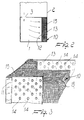
- Figure 1 is a diagrammatic representation of the device according to the invention applied to a medium voltage switchboard;
- Figure 2 is a diagrammatic representation of the device showing the zone of connection to the electrical switchboard;
- Figure 3 is a diagrammatic representation of a body permeable to the passage of the fumes made using a pack of wire nets;
- Figure 4 is a diagrammatic representation of a body permeable to the passage of the fumes made using superimposed corrugated plates.
-
- With reference to the said figures, the device for extinguishing the flame particularly in medium voltage electrical switchboards according to the invention comprises a
compartment 1 that can be connected to thecabinet 2 of a medium voltage switchboard and is in communication with the inside of the switchboard by means of athrough hole 3. - The
compartment 1 is open towards the outside by means of a hole that is closed by a body, indicated byreference number 10, which is permeable to the passage of the fumes that might possibly be emitted inside the electrical switchboard and propagate towards the outside through thecompartment 1. - The distinctive feature of the invention is constituted by the fact that the
body 10 comprises aframework 11 that supports a firstperforated plate 12 and a secondperforated plate 13 that are spaced apart from one another for a distance greater than 50 mm and have a plurality of throughholes 14 that are uniformly distributed. - A mass with very low thermal inertia is provided inside the zone delimited between the
plates - The distinctive feature of the invention is therefore to obtain flame extinction by exploiting a mass, preferably metal, that, by instantly absorbing the heat of the fumes, reduces the temperature and prevents the propagation of the flame.
- In one embodiment of the invention, the low thermal inertia mass is made of stainless steel shavings packed in the zone between the
plates - Alternatively, as illustrated in figure 3, the low thermal inertia mass is formed by a pack of
wire nets 15 with a fine mesh that preferably has a pitch of an average of approximately 0.2 mm or less. - It has been found form experimental tests that a distance of greater than 50 mm between the plates at 12 and 13 is optimal in order to create a relatively high mass.
- It is also possible to obtain the low thermal inertia mass using a pack of
plates 20 that are superimposed in relation to one another, said pack of plates being formed ofcorrugated plates 22 alternated withflat plates 21, so that they create a plurality of very small channels in which the fumes in transit instantaneously transfer their heat to the metal mass of the plates that delimit the channels, thus obtaining the sharp drop in temperature that generates the extinction of the flame. - Metal materials such as stainless steel are preferably used, but it is conceptually possible to use other materials, which obviously have a low thermal inertia and are therefore able to instantly absorb the heat of the fumes.
- From the above-given description it is thus evident how the invention achieves the intended aims and in particular it is pointed out that, according to the invention, the device for extinguishing the flame, particularly in medium voltage electrical switchboards, makes it possible to provide a guarantee against the propagation of the flame by exploiting a new constructional criteria that is extremely valid from a practical standpoint and easy to make.
Claims (5)
- A device for extinguishing the flame particularly in medium voltage electrical switchboards, characterised in that it comprises:a body (10), in the path for realising the fumes produced by the occurrence of an arc inside an electrical switchboard (2), which is permeable to the passage of the fumes and which is made of a mass (15, 20) with low thermal inertia, capable of absorbing heat to extinguish the flame by cooling, and which comprises a first perforated plate (12) and a second perforated plate (13) distanced apart from one another, the distance between said first perforated plated (12) and said second perforated plate (13) being larger than 50 mm;a compartment (1) for the passage of the fumes in communication with the inside of said electrical switchboard (2), said compartment (1) featuring an exit hole towards the outside closed by said body (10) that is permeable to the passage of the fumes.
- A device, according to claim 1, characterised in that said mass (15, 20) with low thermal inertia is made of stainless steel shavings.
- A device, according to one or more of previous claims, characterised by the fact that said mass (15, 20) with low thermal inertia is formed by a pack of wire nets (15), which lay substantially parallel to said first perforated plate (12) and to said second perforated plate (13).
- A device, according to one or more of previous claims, characterised by the fact that said wire nets (15) have meshes with an average pitch that is approximately 0.2 mm.
- A device, according to one or more of previous claims, characterised in that said mass (15, 20) with low thermal inertia is formed by corrugated plates (22) alternating with a plurality of flat plates (21), creating a plurality of small channels running between said first perforated plate (12) and said second perforated plate (13).
Applications Claiming Priority (2)
| Application Number | Priority Date | Filing Date | Title |
|---|---|---|---|
| ITMI971736 | 1997-07-22 | ||
| IT97MI001736A IT1293755B1 (en) | 1997-07-22 | 1997-07-22 | DEVICE FOR EXTINGUISHING THE FLAME PARTICULARLY IN MEDIUM VOLTAGE ELECTRICAL PANELS |
Publications (2)
| Publication Number | Publication Date |
|---|---|
| EP0903826A1 EP0903826A1 (en) | 1999-03-24 |
| EP0903826B1 true EP0903826B1 (en) | 2002-04-24 |
Family
ID=11377605
Family Applications (1)
| Application Number | Title | Priority Date | Filing Date |
|---|---|---|---|
| EP98202429A Expired - Lifetime EP0903826B1 (en) | 1997-07-22 | 1998-07-20 | Fire extinguishing device, especially for medium voltage switchboards |
Country Status (5)
| Country | Link |
|---|---|
| EP (1) | EP0903826B1 (en) |
| AT (1) | ATE216807T1 (en) |
| DE (1) | DE69805032T2 (en) |
| ES (1) | ES2176900T3 (en) |
| IT (1) | IT1293755B1 (en) |
Families Citing this family (6)
| Publication number | Priority date | Publication date | Assignee | Title |
|---|---|---|---|---|
| DE202004020060U1 (en) * | 2004-01-21 | 2005-03-10 | Ormazabal Anlagentechnik Gmbh | guide |
| CN1312711C (en) * | 2004-02-20 | 2007-04-25 | 浙江正泰电器股份有限公司 | Arc suppressing room with gas deionization device |
| DE102008024069A1 (en) * | 2008-05-17 | 2009-11-26 | Areva Energietechnik Gmbh | Electrical switching unit, in particular for the medium-voltage range |
| DE102018206577A1 (en) | 2018-04-27 | 2019-10-31 | Siemens Aktiengesellschaft | switch cabinet |
| EP3671993B1 (en) * | 2018-12-20 | 2022-05-25 | ABB Schweiz AG | Electrical arc absorber system, a switchgear having an electrical arc absorber system and method for operating a switchgear |
| CN115360595B (en) * | 2022-08-22 | 2023-04-28 | 宇超电力股份有限公司 | Armored centrally-mounted metal-enclosed switch cabinet and application method thereof |
Family Cites Families (13)
| Publication number | Priority date | Publication date | Assignee | Title |
|---|---|---|---|---|
| FR561531A (en) * | 1922-01-31 | 1923-10-23 | Thomson Houston Comp Francaise | Protective device for electrical appliances placed in a closed enclosure |
| US3033961A (en) * | 1960-05-04 | 1962-05-08 | Ite Circuit Breaker Ltd | Serpentine corrugated arc product coolers |
| US3230331A (en) * | 1965-04-26 | 1966-01-18 | S & C Electric Co | Circuit interrupter construction with improved condenser |
| US3555224A (en) * | 1968-12-23 | 1971-01-12 | Gen Electric | Arc chute for an air circuit breaker |
| DE2817418A1 (en) * | 1978-04-18 | 1979-10-25 | Krone Gmbh | Distribution board gas outflow arrangement - uses at least one outflow duct with filtering unit provided at upper and lower ends and has large additional filter |
| DE3424363A1 (en) * | 1984-07-03 | 1986-01-09 | Ritter Starkstromtechnik GmbH & Co, 4600 Dortmund | Electrical installations which are proof against disturbing arcs |
| DE3525143C2 (en) * | 1985-07-13 | 1993-10-14 | Driescher Spezialfab Fritz | Transformer station |
| DE3541514A1 (en) * | 1985-11-21 | 1987-05-27 | Siemens Ag | ARC EXTINGUISHING CHAMBER WITH AN ATTACHMENT FOR FURTHER COOLING OF LEAKING GASES |
| KR930010967B1 (en) * | 1989-09-18 | 1993-11-18 | 미쯔비시 덴끼 가부시기가이샤 | Current limiting circuit breaker |
| DE4141685C2 (en) * | 1991-12-18 | 1996-07-04 | Sachsenwerk Ag | Switchgear for medium or high voltage |
| DE4403355A1 (en) * | 1994-02-03 | 1995-08-10 | Gec Alsthom T & D Gmbh | Arc absorber |
| DE19520698C2 (en) * | 1995-06-07 | 1997-10-23 | Ritter Starkstromtech | Electrical system, in particular switchgear |
| FR2750531B1 (en) * | 1996-06-28 | 1998-08-07 | Schneider Electric Sa | GAS DEIONIZATION DEVICE IN PARTICULAR CUTTING GASES IN AN ARC EXTINGUISHING CHAMBER OF A LOW VOLTAGE CIRCUIT BREAKER WITH MOLDED BOX AND ARC EXTINGUISHING CHAMBER EQUIPPED WITH THIS DEVICE |
-
1997
- 1997-07-22 IT IT97MI001736A patent/IT1293755B1/en active IP Right Grant
-
1998
- 1998-07-20 EP EP98202429A patent/EP0903826B1/en not_active Expired - Lifetime
- 1998-07-20 ES ES98202429T patent/ES2176900T3/en not_active Expired - Lifetime
- 1998-07-20 DE DE69805032T patent/DE69805032T2/en not_active Expired - Lifetime
- 1998-07-20 AT AT98202429T patent/ATE216807T1/en not_active IP Right Cessation
Also Published As
| Publication number | Publication date |
|---|---|
| ITMI971736A1 (en) | 1999-01-22 |
| DE69805032D1 (en) | 2002-05-29 |
| EP0903826A1 (en) | 1999-03-24 |
| ATE216807T1 (en) | 2002-05-15 |
| ES2176900T3 (en) | 2002-12-01 |
| IT1293755B1 (en) | 1999-03-10 |
| DE69805032T2 (en) | 2002-12-19 |
Similar Documents
| Publication | Publication Date | Title |
|---|---|---|
| JP2021517708A (en) | An ESS module having a structure capable of preventing the leakage of flames to the outside and a battery pack containing the ESS module. | |
| EP0903826A1 (en) | Fire extinguishing device, especially for medium voltage switchboards | |
| JP2000106490A (en) | Circuit board cabinet | |
| CA2377835A1 (en) | Pressure relief panel for arc resistant cabinets | |
| CA1331776C (en) | Barrier with a venting scheme for a circuit breaker | |
| RU2380807C2 (en) | Discharger of overvoltage protection with two divergent electrodes and spark gap between them | |
| CN110676708A (en) | Cubical switchboard that fire behavior is high | |
| MY124649A (en) | Explosion preventing device for refrigerating machine using flammable refrigerant | |
| SK18298A3 (en) | Overvoltage arrester device | |
| ZA200103426B (en) | Spark gap arrangement. | |
| HU213360B (en) | Protective power switch with arc extinguishing chamber | |
| CN105374648B (en) | Low-voltage circuit breaker disappears free arc-control device | |
| CN119153163A (en) | Fireproof flame-retardant pressure-resistant cable | |
| KR20230130265A (en) | Air circuit breaker having insulation paper to prevent terminal short circuit | |
| CN222233560U (en) | Gas generating piece, arc extinguishing device and switching device | |
| AU2003235388B2 (en) | Arc-resistant switchgear enclosure | |
| CN220543779U (en) | Arc extinguishing device of circuit breaker | |
| KR200415012Y1 (en) | Multifunctional prefabricated panel | |
| CN121035516B (en) | A flame arrestor for power supply components in new energy vehicles | |
| CN207199554U (en) | A kind of arc-control device of Modularized molded-case circuit breaker zero and the breaker containing the device | |
| PL174603B1 (en) | Switch | |
| CN118352201A (en) | Gas-generating parts, arc-extinguishing devices and switching devices | |
| CN213241969U (en) | Fire-retardant low smoke and zero halogen fire resisting cable for fire extinguishing system | |
| US4453055A (en) | Louvered arc chute | |
| CN117727595B (en) | Arc extinguishing chamber of circuit breaker |
Legal Events
| Date | Code | Title | Description |
|---|---|---|---|
| PUAI | Public reference made under article 153(3) epc to a published international application that has entered the european phase |
Free format text: ORIGINAL CODE: 0009012 |
|
| AK | Designated contracting states |
Kind code of ref document: A1 Designated state(s): AT BE CH DE DK ES FI FR GB IT LI NL SE |
|
| AX | Request for extension of the european patent |
Free format text: AL;LT;LV;MK;RO;SI |
|
| 17P | Request for examination filed |
Effective date: 19990921 |
|
| AKX | Designation fees paid |
Free format text: AT BE CH DE DK ES FI FR GB IT LI NL SE |
|
| 17Q | First examination report despatched |
Effective date: 20000725 |
|
| GRAG | Despatch of communication of intention to grant |
Free format text: ORIGINAL CODE: EPIDOS AGRA |
|
| GRAG | Despatch of communication of intention to grant |
Free format text: ORIGINAL CODE: EPIDOS AGRA |
|
| GRAH | Despatch of communication of intention to grant a patent |
Free format text: ORIGINAL CODE: EPIDOS IGRA |
|
| GRAH | Despatch of communication of intention to grant a patent |
Free format text: ORIGINAL CODE: EPIDOS IGRA |
|
| REG | Reference to a national code |
Ref country code: GB Ref legal event code: IF02 |
|
| GRAA | (expected) grant |
Free format text: ORIGINAL CODE: 0009210 |
|
| AK | Designated contracting states |
Kind code of ref document: B1 Designated state(s): AT BE CH DE DK ES FI FR GB IT LI NL SE |
|
| PG25 | Lapsed in a contracting state [announced via postgrant information from national office to epo] |
Ref country code: NL Free format text: LAPSE BECAUSE OF FAILURE TO SUBMIT A TRANSLATION OF THE DESCRIPTION OR TO PAY THE FEE WITHIN THE PRESCRIBED TIME-LIMIT Effective date: 20020424 Ref country code: LI Free format text: LAPSE BECAUSE OF FAILURE TO SUBMIT A TRANSLATION OF THE DESCRIPTION OR TO PAY THE FEE WITHIN THE PRESCRIBED TIME-LIMIT Effective date: 20020424 Ref country code: FI Free format text: LAPSE BECAUSE OF FAILURE TO SUBMIT A TRANSLATION OF THE DESCRIPTION OR TO PAY THE FEE WITHIN THE PRESCRIBED TIME-LIMIT Effective date: 20020424 Ref country code: CH Free format text: LAPSE BECAUSE OF FAILURE TO SUBMIT A TRANSLATION OF THE DESCRIPTION OR TO PAY THE FEE WITHIN THE PRESCRIBED TIME-LIMIT Effective date: 20020424 Ref country code: BE Free format text: LAPSE BECAUSE OF FAILURE TO SUBMIT A TRANSLATION OF THE DESCRIPTION OR TO PAY THE FEE WITHIN THE PRESCRIBED TIME-LIMIT Effective date: 20020424 Ref country code: AT Free format text: LAPSE BECAUSE OF FAILURE TO SUBMIT A TRANSLATION OF THE DESCRIPTION OR TO PAY THE FEE WITHIN THE PRESCRIBED TIME-LIMIT Effective date: 20020424 |
|
| REF | Corresponds to: |
Ref document number: 216807 Country of ref document: AT Date of ref document: 20020515 Kind code of ref document: T |
|
| REG | Reference to a national code |
Ref country code: GB Ref legal event code: FG4D |
|
| REG | Reference to a national code |
Ref country code: CH Ref legal event code: EP |
|
| REF | Corresponds to: |
Ref document number: 69805032 Country of ref document: DE Date of ref document: 20020529 |
|
| PG25 | Lapsed in a contracting state [announced via postgrant information from national office to epo] |
Ref country code: SE Free format text: LAPSE BECAUSE OF FAILURE TO SUBMIT A TRANSLATION OF THE DESCRIPTION OR TO PAY THE FEE WITHIN THE PRESCRIBED TIME-LIMIT Effective date: 20020724 Ref country code: DK Free format text: LAPSE BECAUSE OF FAILURE TO SUBMIT A TRANSLATION OF THE DESCRIPTION OR TO PAY THE FEE WITHIN THE PRESCRIBED TIME-LIMIT Effective date: 20020724 |
|
| NLV1 | Nl: lapsed or annulled due to failure to fulfill the requirements of art. 29p and 29m of the patents act | ||
| REG | Reference to a national code |
Ref country code: CH Ref legal event code: PL |
|
| REG | Reference to a national code |
Ref country code: ES Ref legal event code: FG2A Ref document number: 2176900 Country of ref document: ES Kind code of ref document: T3 |
|
| PLBE | No opposition filed within time limit |
Free format text: ORIGINAL CODE: 0009261 |
|
| STAA | Information on the status of an ep patent application or granted ep patent |
Free format text: STATUS: NO OPPOSITION FILED WITHIN TIME LIMIT |
|
| 26N | No opposition filed |
Effective date: 20030127 |
|
| PGFP | Annual fee paid to national office [announced via postgrant information from national office to epo] |
Ref country code: GB Payment date: 20120719 Year of fee payment: 15 |
|
| PGFP | Annual fee paid to national office [announced via postgrant information from national office to epo] |
Ref country code: ES Payment date: 20120726 Year of fee payment: 15 Ref country code: DE Payment date: 20120720 Year of fee payment: 15 Ref country code: FR Payment date: 20120806 Year of fee payment: 15 Ref country code: IT Payment date: 20120731 Year of fee payment: 15 |
|
| GBPC | Gb: european patent ceased through non-payment of renewal fee |
Effective date: 20130720 |
|
| REG | Reference to a national code |
Ref country code: FR Ref legal event code: ST Effective date: 20140331 |
|
| PG25 | Lapsed in a contracting state [announced via postgrant information from national office to epo] |
Ref country code: GB Free format text: LAPSE BECAUSE OF NON-PAYMENT OF DUE FEES Effective date: 20130720 Ref country code: DE Free format text: LAPSE BECAUSE OF NON-PAYMENT OF DUE FEES Effective date: 20140201 |
|
| REG | Reference to a national code |
Ref country code: DE Ref legal event code: R119 Ref document number: 69805032 Country of ref document: DE Effective date: 20140201 |
|
| PG25 | Lapsed in a contracting state [announced via postgrant information from national office to epo] |
Ref country code: IT Free format text: LAPSE BECAUSE OF NON-PAYMENT OF DUE FEES Effective date: 20130720 Ref country code: FR Free format text: LAPSE BECAUSE OF NON-PAYMENT OF DUE FEES Effective date: 20130731 |
|
| REG | Reference to a national code |
Ref country code: ES Ref legal event code: FD2A Effective date: 20140807 |
|
| PG25 | Lapsed in a contracting state [announced via postgrant information from national office to epo] |
Ref country code: ES Free format text: LAPSE BECAUSE OF NON-PAYMENT OF DUE FEES Effective date: 20130721 |