EP0901422B1 - Motor vehicle power train - Google Patents
Motor vehicle power train Download PDFInfo
- Publication number
- EP0901422B1 EP0901422B1 EP97926092A EP97926092A EP0901422B1 EP 0901422 B1 EP0901422 B1 EP 0901422B1 EP 97926092 A EP97926092 A EP 97926092A EP 97926092 A EP97926092 A EP 97926092A EP 0901422 B1 EP0901422 B1 EP 0901422B1
- Authority
- EP
- European Patent Office
- Prior art keywords
- transmission
- drive
- power train
- differential
- input
- Prior art date
- Legal status (The legal status is an assumption and is not a legal conclusion. Google has not performed a legal analysis and makes no representation as to the accuracy of the status listed.)
- Expired - Lifetime
Links
Images



Classifications
-
- B—PERFORMING OPERATIONS; TRANSPORTING
- B60—VEHICLES IN GENERAL
- B60K—ARRANGEMENT OR MOUNTING OF PROPULSION UNITS OR OF TRANSMISSIONS IN VEHICLES; ARRANGEMENT OR MOUNTING OF PLURAL DIVERSE PRIME-MOVERS IN VEHICLES; AUXILIARY DRIVES FOR VEHICLES; INSTRUMENTATION OR DASHBOARDS FOR VEHICLES; ARRANGEMENTS IN CONNECTION WITH COOLING, AIR INTAKE, GAS EXHAUST OR FUEL SUPPLY OF PROPULSION UNITS IN VEHICLES
- B60K17/00—Arrangement or mounting of transmissions in vehicles
- B60K17/34—Arrangement or mounting of transmissions in vehicles for driving both front and rear wheels, e.g. four wheel drive vehicles
- B60K17/344—Arrangement or mounting of transmissions in vehicles for driving both front and rear wheels, e.g. four wheel drive vehicles having a transfer gear
- B60K17/346—Arrangement or mounting of transmissions in vehicles for driving both front and rear wheels, e.g. four wheel drive vehicles having a transfer gear the transfer gear being a differential gear
-
- B—PERFORMING OPERATIONS; TRANSPORTING
- B60—VEHICLES IN GENERAL
- B60K—ARRANGEMENT OR MOUNTING OF PROPULSION UNITS OR OF TRANSMISSIONS IN VEHICLES; ARRANGEMENT OR MOUNTING OF PLURAL DIVERSE PRIME-MOVERS IN VEHICLES; AUXILIARY DRIVES FOR VEHICLES; INSTRUMENTATION OR DASHBOARDS FOR VEHICLES; ARRANGEMENTS IN CONNECTION WITH COOLING, AIR INTAKE, GAS EXHAUST OR FUEL SUPPLY OF PROPULSION UNITS IN VEHICLES
- B60K17/00—Arrangement or mounting of transmissions in vehicles
- B60K17/04—Arrangement or mounting of transmissions in vehicles characterised by arrangement, location or kind of gearing
- B60K17/06—Arrangement or mounting of transmissions in vehicles characterised by arrangement, location or kind of gearing of change-speed gearing
- B60K17/08—Arrangement or mounting of transmissions in vehicles characterised by arrangement, location or kind of gearing of change-speed gearing of mechanical type
-
- B—PERFORMING OPERATIONS; TRANSPORTING
- B60—VEHICLES IN GENERAL
- B60K—ARRANGEMENT OR MOUNTING OF PROPULSION UNITS OR OF TRANSMISSIONS IN VEHICLES; ARRANGEMENT OR MOUNTING OF PLURAL DIVERSE PRIME-MOVERS IN VEHICLES; AUXILIARY DRIVES FOR VEHICLES; INSTRUMENTATION OR DASHBOARDS FOR VEHICLES; ARRANGEMENTS IN CONNECTION WITH COOLING, AIR INTAKE, GAS EXHAUST OR FUEL SUPPLY OF PROPULSION UNITS IN VEHICLES
- B60K17/00—Arrangement or mounting of transmissions in vehicles
- B60K17/22—Arrangement or mounting of transmissions in vehicles characterised by arrangement, location, or type of main drive shafting, e.g. cardan shaft
-
- B—PERFORMING OPERATIONS; TRANSPORTING
- B60—VEHICLES IN GENERAL
- B60K—ARRANGEMENT OR MOUNTING OF PROPULSION UNITS OR OF TRANSMISSIONS IN VEHICLES; ARRANGEMENT OR MOUNTING OF PLURAL DIVERSE PRIME-MOVERS IN VEHICLES; AUXILIARY DRIVES FOR VEHICLES; INSTRUMENTATION OR DASHBOARDS FOR VEHICLES; ARRANGEMENTS IN CONNECTION WITH COOLING, AIR INTAKE, GAS EXHAUST OR FUEL SUPPLY OF PROPULSION UNITS IN VEHICLES
- B60K5/00—Arrangement or mounting of internal-combustion or jet-propulsion units
- B60K5/02—Arrangement or mounting of internal-combustion or jet-propulsion units with the engine main axis, e.g. crankshaft axis, substantially in or parallel to the longitudinal centre line of the vehicle
-
- Y—GENERAL TAGGING OF NEW TECHNOLOGICAL DEVELOPMENTS; GENERAL TAGGING OF CROSS-SECTIONAL TECHNOLOGIES SPANNING OVER SEVERAL SECTIONS OF THE IPC; TECHNICAL SUBJECTS COVERED BY FORMER USPC CROSS-REFERENCE ART COLLECTIONS [XRACs] AND DIGESTS
- Y10—TECHNICAL SUBJECTS COVERED BY FORMER USPC
- Y10T—TECHNICAL SUBJECTS COVERED BY FORMER US CLASSIFICATION
- Y10T74/00—Machine element or mechanism
- Y10T74/19—Gearing
- Y10T74/19023—Plural power paths to and/or from gearing
- Y10T74/19074—Single drive plural driven
- Y10T74/19079—Parallel
- Y10T74/19093—Spur and bevel
Definitions
- the invention relates to a motor vehicle power trains and is particularly concerned with a power trains of four wheel drive vehicles of the type which have a longitudinally mounted engine.
- Known power trains of conventional four wheel drive vehicles typically comprise a change speed transmission mounted axially in line with the engine and a transfer transmission which is mounted directly on the change speed transmission to drive front and rear differentials through propshafts offset from the engine and the change speed transmission.
- a separate transfer transmission is spaced from the change speed transmission and connected to it through a short universally jointed propshaft.
- Packaging of power trains in motor vehicles is of increasing importance particularly as vehicles become more compact and available space decreases. This creates a conflict for the vehicle designer between providing adequate accommodation for the driver and passengers and mounting the power train components in an arrangement most appropriate for their function of driving the vehicle.
- FR-A-2 695 880 shows a transmission which is intended for a sports car and the object is to move the weight of the transmission assembly close to the rear wheels so that there is a balanced distribution of load between the two axles of the vehicle.
- FR-A-2 695 880 couples the transmission assembly directly to the rear differential casing so that the rear output from the centre differential is taken directly by the bevel pinion shaft.
- An object of the present invention is to provide a motor vehicle power train which helps to optimise the available space without any of the disadvantages outlined above.
- a power train for a motor vehicle is characterised in that the transmission assembly is separate from the rear differential and placed at or near the centre of the vehicle and is spaced from the rear differential by a rear propshaft which drivably connects the rear differential to the rear rotary output.
- the change speed transmission may be coaxial with the hollow output shaft, an input transmission being adapted to transmit drive from the drive axially offset from the rotary input, the front rotary output by an amount greater than that of the rear rotary output.
- the change speed transmission may be coaxial with the hollow output shaft, an input transmission being adapted to transmit drive from the drive input to the input shaft of the change speed transmission, in which case the input transmission and the auxiliary output transmission are conveniently arranged at the same end of the transmission assembly.
- This arrangement is particularly suitable where the change speed transmission is an epicyclic type automatic transmission or a toroidal type CVT.
- the change speed transmission may be a layshaft type having an input shaft coaxial with the rotary input and axially offset from the hollow output shaft.
- This arrangement is particularly suitable where the change speed transmission is a constant mesh type, e.g. synchromesh or is a belt and pulley type CVT.
- the transfer transmission may include an epicyclic final drive having a sun gear connected to the hollow output shaft and a planet gear carrier for transmitting drive to the centre differential, in which case the epicyclic final drive may provide a plurality of selectable ratios.
- the transmission assembly is spaced from the engine, the rotary input being connected to the engine by an input propshaft, in which case a drive coupling (e.g. torque converter or friction clutch) in the drive between the engine and the transmission assembly can be mounted on the engine so as to be operable to transmit drive to the transmission assembly through the input propshaft.
- a bell housing for the drive coupling can be mounted on the engine and, as an alternative to independent mounting of the engine and the transmission assembly, the bell housing and the transmission assembly can be connected by a tubular housing which surrounds the input propshaft.
- the transmission assembly can comprise a drive coupling (particularly a torque converter) in the drive between the engine and the change speed transmission.
- a drive coupling particularly a torque converter
- a pump for the change speed transmission is conveniently located on the opposite side of the torque converter to the engine.
- the transmission assembly is in use mounted substantially midway between the front and rear differentials. This helps to reduce the polar moment of inertia of the vehicle and improves handling.
- the front and rear propshafts can be of substantially equal length. This is particularly advantageous where rigid axles are used and both of the front and rear differentials form part of the unsprung weight of the vehicle.
- the change speed transmission includes rotary drive components and selector components substantially identical to those produced for a change speed transmission used in a front wheel drive motor vehicle. This helps to reduce tooling costs and development time.
- the change speed transmission may include a casing component substantially identical to one produced for a change speed transmission used in a front wheel drive motor vehicle.
- a motor vehicle which incorporates a power train according to said one aspect of the invention.
- the transmission assembly can be housed partly within a tunnel or cavity in a floor of the motor vehicle. This minimises the effect of any intrusion into the passenger compartment.
- the tunnel or cavity may project upwardly between the foot wells for front and rear passengers, again minimising the effect of any intrusion into the passenger compartment.
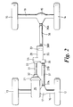
- a motor vehicle 11 includes a pair of front wheels 12, 13 and a pair of rear wheels 14, 15.
- the front wheels 12, 13 are carried by a front axle 16 having a differential unit 17.
- the rear wheels 14, 15 are carried by a rear axle 18 having a differential unit 19.
- the front axle 17 is suspended from a vehicle chassis 21 by means of leading links 22 and coil springs 23.
- the rear axle 18 is suspended from the chassis 21 by means of trailing links 24 and air springs 25.
- the front and rear axles 16, 18 form part of a power train which also includes an engine 26, a bell housing 27 which covers a torque converter attached to a crankshaft of the engine 26 and a transmission assembly 35 mounted spaced from and independently of the engine 26.
- the transmission assembly 35 is drivably connected to the engine 26 by an input propshaft 31 having universal joints 32 and 33 arranged one each end, the rearmost joint 33 acting as a rotary input for the transmission assembly 35.
- the transmission assembly 35 includes an automatic change speed transmission 28 and a transfer transmission 30, drive from the input propshaft 31 being transmitted to the change speed transmission 28 through an input transmission 34 which will be described in more detail below.
- the transfer transmission 30 is drivingly connected to the front differential 17 by a front propshaft 37 having universal joints 37A and 37B and to the rear differential 19 through a rear propshaft 38 having universal joints 38A and 38B, the rearmost joint 37B of the front propshaft 37 acting as a front rotary output for the transmission assembly 35 and the front joint 38B of the rear propshaft 38 acting as a rear rotary output for the transmission assembly.
- Drive from the transfer transmission 30 to the front propshaft 37 is transmitted through an output transmission 39 which is also described in more detail below.
- the rotary input (universal joint 33) and the front and rear rotary outputs (universal joints 37B and 38B) are staggered or axially offset, i.e. their axes are offset from each other, the offset between the rotary input and the front rotary output being greater than that between the rotary input and the rear rotary output.
- the drive train of the existing transmission assembly 35A of a front wheel drive vehicle as shown in Fig.3 comprises a bell housing 40 which is normally mounted on to an engine 42 and houses a torque converter 43.
- a housing 45 for a valve block 46 and a pump 47 is also mounted on the bell housing 40. the pump 47 receiving drive from the engine 42 in known manner.
- Drive from the torque converter 43 is transmitted by a driving sprocket 60A, a chain 44 and a driven sprocket 62A to the hollow input shaft 61 of an automatic change speed transmission 28A which contains a series of epicyclic gear trains, clutches and brakes which enable drive ratios for the vehicle to be selected in known manner.
- the change speed transmission 28A includes a hollow output shaft 49.
- the transmission assembly 35A has an epicyclic final drive 29A which gives a required final drive ratio and transmits drive to a differential 52.
- a shaft 54 extends from one side of the differential 52 coaxially through the hollow output shaft 49 and other parts of the automatic change speed transmission 28A for driving a front wheel on one side of the vehicle and another shaft 56 extends from the other side of the differential for driving a front wheel on the other side of the vehicle.
- the transmission assembly shown in Fig.3 is modified as described below to form part of a power train in accordance with the present invention.
- modification will be understood to include design modification (for series production) as well as modification of actual components (for feasibility prototypes and very low volume production).
- a number of rotary drive components and selector components e.g. clutches and brakes
- casing components in this way.
- Fig.4 shows a first stage in the modification in which the torque converter 43 has been removed and an end cover 58 put in its place.
- a torque converter 43A is instead housed within the bell housing 27 and transmits drive through the input propshaft 31 so as to drive the pump 47 and the automatic change speed transmission 28B.
- the torque converter 43A is connected to the pump 47 and valve block 46 by pipes (not shown) and a muff coupling for operation of the usual lock-up clutch in the torque converter.
- the pump 47 may alternatively be replaced by another pump (not shown) driven directly by the engine or supplemented by an auxiliary engine driven pump.
- the shaft 54 is used to connect to the front propshaft 37 and the shaft 56 used to connect to the rear propshaft 38, the epicyclic final drive 29A and the differential 52 serving as a transfer transmission in which the differential 52 acts as a centre differential to allow variations between the speeds of the front and rear wheels 12, 13, 14, 15.
- Fig.5 shows diagrammatically the final stage of modification, this being the stage shown in the power train in Figs. 1 and 2.
- the shaft 54 carries a gear 64 which meshes with a gear 66 drivably connected to the front propshaft 37 in substantially a 1:1 ratio, the gears 64, 66 providing the auxiliary output transmission 39.
- the shaft 56 driven by the differential 52 is drivably connected to the rear propshaft 38.
- the input transmission 34 and the output transmission 39 are arranged at the same end of the change speed transmission 28 and that instead of the chain 44 and sprockets 60A, 62A, the input transmission comprises meshing spur gears 60, 62.
- Fig.6 shows in some detail the finally modified transfer transmission 30, particularly the epicyclic final drive 29.
- the hollow output shaft 49 of the change speed transmission 28 has a portion 70 which is connected through splines 72 to a sun gear 74.
- the sun gear 74 meshes with a series of planet gears 76 which are mounted for rotation on pins 78 of a planet gear carrier 80.
- the planet gears 76 also mesh with an annulus gear 82 fixed to a casing 84 of the change speed transmission 28.
- the planet gear carrier 80 has an annular extension 86 formed with a circumferential row of axial splines 88 which, for convenience of manufacture, are identical to the splines 72.
- a selector member 90 is slidably mounted on splines 92 formed on a drive member 94 of the differential 52.
- the selector member 90 is formed with a circumferential row of splines 96 which can be slid optionally into engagement with the splines 72 on the sun gear 74 or with the splines 88 on the planet gear carrier 80.
- the drive member 94 is mounted for rotation in a bearing 98 on the housing 84.
- the differential 52 is of known kind and may he a limited slip type, e.g. a Torsen (Trade Mark).
- a suitable selector mechanism 100 part of which is shown in Fig.6. is provided for shifting the selector member 90. Operation of the epicyclic final drive 29 will now be described.
- drive in high range to the shafts 54, 56 is provided by shifting the selector member 90 to interengage the splines 72 and 96, drive from the hollow output shaft 49 being transmitted directly to the drive member 94.
- the selector member 90 is shifted so as to interengage the splines 88 of the planet gear carrier 80 with the splines 96 of the selector member 90. In that way, drive from the hollow output shaft 49 will be transmitted through the planetary gearing and out through the planet gear carrier 80 via the selector member 90 so as to rotate the drive member 94 at a reduction ratio.
- the epicyclic final drive 29 is readily adaptable from a known epicyclic transmission already used to provide high and low ranges on a four wheel drive vehicle.
- the auxiliary output transmission 39 applies torque to the front propshaft 37 in a direction which is opposite to that applied to the rear propshaft 38, i.e. they normally rotate in opposite directions. That is advantageous in that torque reaction from the front and rear propshafts 37, 38 is thereby cancelled.
- the auxiliary output transmission 39 could be arranged so that the front propshaft 37 to rotate in the same direction as the rear propshaft 38, e.g. by using sprockets and a chain similar to the input transmission 34A in Fig.4 and modifying the gearing of the front differential 17.
- Fig.7 shows a modified transmission assembly 35C in which a synchromesh type of change speed transmission 110 is used instead of the epicyclic type automatic change speed transmission 28.
- Synchromesh transmissions are normally manually operated but, as is now well known, can be adapted for automatic or semiautomatic operation using servo-actuators.
- Parts in Fig.7 which correspond to parts shown in Figs.1 to 6 carry the same reference numerals and will not be described in detail.
- the engine 26 transmits drive via a clutch (not shown) in the bell housing 27 and an input propshaft 31 having universal joints 32 and 33 arranged one each end.
- Rotating components of the change speed transmission 110 include an input shaft 112 and a hollow output shaft 114.
- the change speed transmission 110 comprises first, second, third, fourth and fifth forward ratio constant mesh gear trains 116, 117, 118, 119 and 120 respectively and a reverse gear train 122.
- the reverse ratio is engaged by moving a reverse idler gear (not shown) into mesh.
- the forward ratios are selected by operating synchromesh clutches by means of a conventional selector mechanism (not shown).
- the hollow output shaft 114 acts as an input shaft for the transfer transmission 30 which may be similar to the transmission 30 shown in detail in Fig.6.
- the transfer transmission 30 includes a centre differential 52 from which drive is transmitted to the front propshaft 37 via a shaft 54 passing through the hollow output shaft 114 and an auxiliary output transmission 39 comprising gear wheels 64, 66 as in Fig.5.
- the centre differential 52 also transmits drive to the rear propshaft 38.
- the synchromesh type change speed transmission 110A can conveniently be substituted by other layshaft type transmissions, including constant mesh types with dog clutches or multiple friction clutches or continuously variable transmissions (CVTs) of the belt and pulley type.
- the epicyclic type of automatic change speed transmission 28 can conveniently be replaced by a CVT of a type having concentric input and output shafts, e.g. a toroidal type such as the Torotrak (Trade Mark), modified as necessary to have a hollow output shaft and a hollow input shaft.
- the transmission assembly 35 or 35C is preferably positioned longitudinally of the power train so that the front and rear propshafts 37, 38 are of substantially equal length. In that way, vibration and harshness caused or exacerbated by the use of excessively short propshafts is reduced and the service life of the associated universal joints can be increased. Moreover, by positioning the transmission assembly 35 or 35C substantially mid way between the axles 16 and 18, the polar moment of inertia of the vehicle can be reduced and the various components of the transmission can be packaged to provide good ground clearance without undue difficulty. In that respect, reference is again made to Fig.1.
- a tunnel or cavity 124 formed in a floor 126 for receiving the auxiliary input transmission 34 of the automatic change speed transmission will be positioned well forward of a rear passenger foot well 128 and will not intrude into a front passenger foot well 130. That feature is particularly advantageous from the point of view of passenger leg room and comfort.
- the auxiliary output transmission 39 can be positioned outside a ground clearance curve indicated at 131 which is most advantageous from the point of view of maintaining optimum ground clearance for the vehicle.
- the synchromesh transmission 110 of Fig.7 is shown in broken outline and it will be seen that a cavity or tunnel 124a needed to clear the transmission 110 does not intrude into the footwells 128, 130.
- a catalytic converter can be positioned close to the engine 26, i.e. with only a short intermediate length of pipe, so that it can reach its operational temperature much sooner than if it is positioned further from the engine.
- a further advantage is that mountings for the engine 26 are required to absorb engine torque only.
- the bell housing 27 and the casing of the transmission assembly 35 or 35C are connected by a tubular housing which surrounds the input propshaft 31. This eliminates the need for universal joints 32, 33.
- the staggering of the front and rear propshafts 37, 38 as will be appreciated from Figs.2 and 5 is also useful from the point of packaging.
- the torque converter 43A may be incorporated in the transmission assembly 35A as shown in Fig.3 with the casing adapted accordingly.
- Drive from the engine 26 will be transmitted to the torque converter 43 through the input propshaft 31 and a shaft concentric with the pump 47.
- the torque converter and the pump and valve block can be transposed so that the pump and valve block are on the opposite side of the torque converter to the engine.
- the input transmission 34 comprises meshing gears 60, 62.
- meshing gears it is envisaged that a chain drive may be used provided that the transmission 28 will finally provide a drive output in the correct rotational direction for the vehicle.
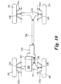
- the transmission assembly 235 is mounted on a bell housing 227 for a torque converter 243 instead of being spaced therefrom and connected thereto by the input propshaft 31.
- the torque converter 243 drives a tubular input shaft 233 which acts as the rotary input to the transmission assembly, the pump 247 being engine driven through a concentric shaft 250.
- First and second meshing gears 260, 262 provide the input transmission to the change speed transmission 228.
- the automatic change speed transmission 228 contains a series of gear trains clutches and brakes to enable drive ratios for the vehicle to be selected in known manner.
- the change speed transmission 228 transmits drive through a hollow output shaft 249 as Fig.4 to an epicyclic transfer transmission 229 which in turn transmits drive to a differential 252.
- the differential 252 drives a shaft 254 extending coaxially through the hollow output shaft 249 and through the remainder of the change speed transmission 228 for driving a front differential 217 via gears 264, 265 and a front propshaft 237.
- the differential 252 also drives a shaft 256 which transmits drive to a rear differential 219 via a rear propshaft 238.
- the front differential 217 transmits drive through front driveshafts 230 for driving front wheels 22, 23 and the rear differential 29 transmits drive through rear driveshafts 232 for driving rear wheels 214, 215.
- the front and rear differentials 217, 219 are mounted on a body or chassis of the vehicle and the front and rear wheels 212, 213, 214 and 215 are carried by respective independent suspensions 212a, 213a, 214a and 215a. It will be noted from Fig.10 that the front propshaft 237 is shorter than the rear propshaft 238, this not being a disadvantage in a vehicle having independent suspension where the front and rear differentials are mounted on the body or chassis of the vehicle. If desired, the meshing gears 260, 262 and 264, 265 can be replaced by respective chain drive arrangements as described above with respect to Fig.5.
- the input propshaft 31 or the tubular input shaft 233 and the front and rear propshafts 37 or 237, 38 or 238 will normally be disposed somewhat as shown in Fig.8, this further illustrating the staggering or axial offset between the rotary input and the front and rear rotary outputs and showing that the front rotary output to the front propshaft 37 or 237 is offset by a greater amount than that of the rear rotary output to the rear propshaft 38 or 238.
- the outputs may be disposed to the other side of the vehicle, as illustrated in Fig.8 by an alternative front propshaft 37C, shown dotted.
- the centre differential 52 or 252 could be at the same end of the transmission assembly as the auxiliary output transmission 39, 239 so that the rear differential output shaft 56 or 236 extends through the hollow output shaft 49 or 114.
Landscapes
- Engineering & Computer Science (AREA)
- Chemical & Material Sciences (AREA)
- Combustion & Propulsion (AREA)
- Transportation (AREA)
- Mechanical Engineering (AREA)
- Arrangement And Driving Of Transmission Devices (AREA)
- Control Of Motors That Do Not Use Commutators (AREA)
- Control Of Multiple Motors (AREA)
- Reciprocating, Oscillating Or Vibrating Motors (AREA)
- Air-Conditioning For Vehicles (AREA)
- Lock And Its Accessories (AREA)
- Arrangement Or Mounting Of Propulsion Units For Vehicles (AREA)
Abstract
Description
Claims (22)
- A power train for a motor vehicle having a pair of front wheels (12, 13) and a pair of rear wheels (14, 15), said power train comprising:characterised in thatan engine (26, 226) which in use, is mounted longitudinally in the vehicle adjacent the front end thereof;a front differential (17) disposed, in use, between the front wheels and drivably connected thereto;a rear differential (19) disposed, in use, between the rear wheels and drivably connected thereto; anda transmission assembly (35, 235) mounted intermediate the front and rear differentials and spaced from the front differential and having:a rotary input (33, 233) drivably connected to the engine;a front rotary output (37B) drivably connected to the font differential through a front propshaft (37) anda rear rotary output (38B) drivably connected to the rear differential:said transmission assembly (35, 235) comprising:a change speed transmission (28, 110, 228) having an input shaft (61, 112) for receiving drive from the rotary input (33, 233) and a hollow output shaft (49, 114);a transfer transmission comprising a centre differential (30, 230) which is drivably connected to the hollow output shaft (49, 114), has a front differential output shaft (54, 254) for transmitting drive to the front rotary output (37B) and a rear differential output shaft (56, 256) for transmitting drive to the rear rotary output (38B), whereby one of the differential output shafts (54, 254) extends coaxially through the hollow output shaft, andan auxiliary output transmission (39, 239) in the drive from the front differential output shaft (54, 254) to the front rotary output (37B)the transmission assembly being arranged so that the front (37B) and rear (38B) rotary outputs are axially offset from the rotary input (33, 233), the front rotary output (37B) by an amount greater than that of the rear rotary output (38B);
the transmission assembly (35, 235) is separate from the rear differential (19) and placed at or near the centre of the vehicle and is spaced from the rear differential by a rear propshaft (38) which drivably connects the rear differential to the rear rotary output (38B). - A power train according to Claim 1 in which the change speed transmission (28, 228) is coaxial with the hollow output shaft, the transmission assembly (35, 235) further comprising an input transmission (34, 234) which is adapted to transmit drive from the drive input (33, 233) to the input shaft (61) of the change speed transmission.
- A power train according to claim 1 in which the change speed transmission (110) is a layshaft type having an input shaft (112) coaxial with the rotary input (33) and axially offset from the hollow output shaft (114).
- A power train according to any preceding claim in which the transfer transmission (30) includes an epicyclic final drive (29) having a sun gear (70) connected to the hollow output shaft and a planet gear carrier (80) for transmitting drive to the centre differential (52).
- A power train according to claim 4 in which the epicyclic final drive provides a plurality of selectable ratios.
- A power train according to any preceding claim in which the transmission assembly (35, 35C) is spaced from the engine (26) and an input propshaft (31) is provided to connect the rotary input (33) to the engine.
- A power train according to claim 6 in which a drive coupling (43A) is provided in the drive between the engine (26) and the transmission assembly ((35, 35C), the drive coupling being mounted on the engine so as to be operable to transmit drive to the transmission assembly through the input propshaft (31).
- A power train according to claim 7 in which the engine includes a bell housing for the drive coupling and the bell housing and the transmission assembly are connected by a tubular housing which surrounds the input propshaft.
- A motor vehicle incorporating a power train according to any preceding claim.
- A motor vehicle according to claim 9 in which the transmission assembly (35, 235) is housed partly within a tunnel or cavity (124, 124A) in a floor (126) of the motor vehicle.
- A power train according to claim 2 in which the input transmission (34, 234) and the auxiliary output transmission (239) are arranged at the same end of the transmission assembly.
- A power train according to claim 1, 2 or 11 in which the change speed transmission is an epicyclic type automatic transmission (28, 228).
- A power train according to claim 2 in which the change speed transmission (110) is an toroidal type CVT.
- A power train according to claim 3 in which the change speed transmission (110) is a constant mesh type.
- A power train according to claim 3 in which the change speed transmission is a belt and pulley type CVT.
- A power train according to claim 6 in which the transmission assembly comprises a drive coupling in the drive between the engine and the change speed transmission.
- A power train according to claim 16 in which the drive coupling is a torque converter and a pump for the change speed transmission is located on the opposite side of the torque converter to the engine.
- A power train according to any of claims 1 to 8 or 11 to 17 in which the transmission assembly (35, 35C) is in use mounted substantially midway between the front and rear differentials (16, 18).
- A power train according to any of claims 1-8 or 11 to 18 in which the front and rear propshafts (37, 38) are of substantially equal length.
- A power train according to any of claims 1-8 or 11 to 19 in which the change speed transmission (28) includes rotary drive components and selector components substantially identical to those produced for a change speed transmission (28A) used in a front wheel drive motor vehicle.
- A power train according to claim 20 in which the change speed transmission (28) includes a casing component substantially identical to one produced for a change speed transmission (28A) used in a front wheel drive motor vehicle.
- A motor vehicle according to claim 10 in which the tunnel or cavity (124, 124A) projects upwardly between the foot wells (128, 130) for front and rear passengers.
Applications Claiming Priority (3)
| Application Number | Priority Date | Filing Date | Title |
|---|---|---|---|
| GBGB9611855.9A GB9611855D0 (en) | 1996-06-06 | 1996-06-06 | A power train for a motor vehicle |
| GB9611855 | 1996-06-06 | ||
| PCT/GB1997/001515 WO1997046406A1 (en) | 1996-06-06 | 1997-06-05 | Motor vehicle power train |
Publications (2)
| Publication Number | Publication Date |
|---|---|
| EP0901422A1 EP0901422A1 (en) | 1999-03-17 |
| EP0901422B1 true EP0901422B1 (en) | 2000-05-10 |
Family
ID=10794857
Family Applications (1)
| Application Number | Title | Priority Date | Filing Date |
|---|---|---|---|
| EP97926092A Expired - Lifetime EP0901422B1 (en) | 1996-06-06 | 1997-06-05 | Motor vehicle power train |
Country Status (6)
| Country | Link |
|---|---|
| US (1) | US6030312A (en) |
| EP (1) | EP0901422B1 (en) |
| AT (1) | ATE192709T1 (en) |
| DE (1) | DE69701979T2 (en) |
| GB (2) | GB9611855D0 (en) |
| WO (1) | WO1997046406A1 (en) |
Families Citing this family (17)
| Publication number | Priority date | Publication date | Assignee | Title |
|---|---|---|---|---|
| GB9518056D0 (en) * | 1995-09-05 | 1995-11-08 | Rover Group | A power train for a motor vehicle |
| US5704866A (en) * | 1996-07-26 | 1998-01-06 | New Venture Gear, Inc. | Transmission for four-wheel drive vehicles |
| AT405157B (en) * | 1997-07-01 | 1999-06-25 | Steyr Daimler Puch Ag | TWO-STAGE DISTRIBUTION GEARBOX FOR A MOTOR VEHICLE |
| US6045476A (en) * | 1999-06-01 | 2000-04-04 | General Motors Corporation | Transfer gearing apparatus for an all wheel drive |
| JP4519296B2 (en) * | 2000-09-14 | 2010-08-04 | 富士重工業株式会社 | Transmission device for four-wheel drive vehicles |
| US20040097836A1 (en) * | 2000-10-06 | 2004-05-20 | Ombrellaro Mark P. | Direct manual examination of remote patient with virtual examination functionality |
| IL141094A0 (en) * | 2001-01-25 | 2002-02-10 | Ran Siman Tov | Continuous variable transmission |
| US6702709B2 (en) * | 2001-04-09 | 2004-03-09 | New Venture Gear, Inc. | Drivetrain for hybrid motor vehicle |
| DE10304813A1 (en) * | 2003-02-06 | 2004-08-19 | Audi Ag | driving device |
| KR101029371B1 (en) * | 2010-10-11 | 2011-04-15 | 대호 (주) | Tractor |
| KR101029376B1 (en) * | 2010-10-11 | 2011-04-15 | 대호 (주) | tractor |
| DE102011011171A1 (en) * | 2011-02-14 | 2012-08-16 | Audi Ag | Drive arrangement for a motor vehicle |
| US10058481B1 (en) | 2016-06-25 | 2018-08-28 | Ronald D. Russo | Safety sealed bottle stopper |
| DE102016214034A1 (en) * | 2016-07-29 | 2018-02-01 | Zf Friedrichshafen Ag | powertrain |
| CN110091666B (en) * | 2018-01-29 | 2024-09-03 | 舍弗勒技术股份两合公司 | Electric axles for motor vehicles |
| DE102018002464A1 (en) * | 2018-03-26 | 2019-09-26 | Neander Motors Aktiengesellschaft | Motor vehicle with four-wheel drive |
| CN115972897A (en) * | 2022-12-20 | 2023-04-18 | 三江瓦力特特种车辆有限公司 | A large-angle transmission device for a vehicle |
Family Cites Families (12)
| Publication number | Priority date | Publication date | Assignee | Title |
|---|---|---|---|---|
| GB453838A (en) * | 1934-03-15 | 1936-09-15 | Daimler Benz Ag | Improvements in and relating to motor vehicles |
| GB860546A (en) * | 1956-07-24 | 1961-02-08 | Ferguson Res Ltd Harry | Improvements in and relating to motor-vehicle transmission systems |
| GB1010322A (en) * | 1961-05-13 | 1965-11-17 | Ferguson Res Ltd Harry | Improvements relating to high performance motor vehicles of lightweight construction |
| DE1655918A1 (en) * | 1966-11-05 | 1970-01-08 | Zahnradfabrik Friedrichshafen | Gearboxes for motor vehicles |
| US4671136A (en) * | 1984-09-27 | 1987-06-09 | Toyota Jidosha Kabushiki Kaisha | Power transmission for four-wheel drive vehicle |
| DE3436759A1 (en) * | 1984-10-06 | 1986-04-10 | Audi AG, 8070 Ingolstadt | CONTINUOUSLY LONG-MOUNTED GEARBOX FOR A MOTOR VEHICLE DRIVEN ON TWO AXLES |
| FR2593754B1 (en) * | 1986-01-31 | 1990-09-07 | Renault | FOUR-DRIVE TRANSMISSION DEVICE |
| US4805720A (en) * | 1986-02-27 | 1989-02-21 | Clenet Alain J M | Vehicle drivetrain |
| JPH03118233A (en) * | 1989-09-29 | 1991-05-20 | Mazda Motor Corp | Power transmission device for vehicle |
| FR2695880B1 (en) * | 1992-09-18 | 1994-10-21 | Renault | Propulsion and longitudinal transmission assembly for four-wheel drive vehicle. |
| DE4417372C2 (en) * | 1994-05-18 | 1996-11-07 | Porsche Ag | Indirect manual transmission for off-road vehicles |
| US5704866A (en) * | 1996-07-26 | 1998-01-06 | New Venture Gear, Inc. | Transmission for four-wheel drive vehicles |
-
1996
- 1996-06-06 GB GBGB9611855.9A patent/GB9611855D0/en active Pending
-
1997
- 1997-06-05 GB GB9824359A patent/GB2326858B/en not_active Expired - Fee Related
- 1997-06-05 EP EP97926092A patent/EP0901422B1/en not_active Expired - Lifetime
- 1997-06-05 US US09/194,690 patent/US6030312A/en not_active Expired - Lifetime
- 1997-06-05 DE DE69701979T patent/DE69701979T2/en not_active Expired - Fee Related
- 1997-06-05 WO PCT/GB1997/001515 patent/WO1997046406A1/en not_active Ceased
- 1997-06-05 AT AT97926092T patent/ATE192709T1/en not_active IP Right Cessation
Also Published As
| Publication number | Publication date |
|---|---|
| GB9824359D0 (en) | 1998-12-30 |
| GB2326858B (en) | 2000-04-12 |
| EP0901422A1 (en) | 1999-03-17 |
| DE69701979T2 (en) | 2000-11-09 |
| WO1997046406A1 (en) | 1997-12-11 |
| US6030312A (en) | 2000-02-29 |
| GB9611855D0 (en) | 1996-08-07 |
| GB2326858A (en) | 1999-01-06 |
| DE69701979D1 (en) | 2000-06-15 |
| ATE192709T1 (en) | 2000-05-15 |
Similar Documents
| Publication | Publication Date | Title |
|---|---|---|
| US6030312A (en) | Motor vehicle power train | |
| US4650202A (en) | Power transmission for four-wheel drive vehicle | |
| US4671136A (en) | Power transmission for four-wheel drive vehicle | |
| US8070638B2 (en) | Dual input planetary final drive | |
| US5692988A (en) | Multiple-speed automatic transmission for an automotive vehicle | |
| US5042610A (en) | Four-wheel drive vehicle | |
| US5827146A (en) | Dual transmission for motorcycles | |
| US6250411B1 (en) | Motor vehicle power train | |
| EP0226666B1 (en) | Four-wheel vehicle drive system | |
| US4754659A (en) | Quill shaft input cluster gear for manual transmission | |
| EP0321621B1 (en) | Continuously variable automotive transmission | |
| US4415058A (en) | Four-wheel drive system for a wheeled vehicle | |
| US4793210A (en) | Compact construction for transversely mounted transmission | |
| US6227995B1 (en) | Drive system for vehicle | |
| JP3808927B2 (en) | Hydraulic-mechanical torque distribution transmission | |
| JPH0311925B2 (en) | ||
| KR101177947B1 (en) | Automatically shiftable motor vehicle transmission | |
| EP0246926A2 (en) | Power transfer device for four-wheel drive | |
| EP0117945B1 (en) | Vehicles incorporating a final drive reduction unit | |
| US5823909A (en) | Multiple speed automatic transaxle for a motor vehicle | |
| EP0242338B1 (en) | Motor vehicle transmission system | |
| GB2064011A (en) | Engine and Transmission Arrangement for Vehicles | |
| EP0524791A2 (en) | T-drive powertrain assembly | |
| US20050245344A1 (en) | Automatic speed changer | |
| JP3832930B2 (en) | Belt type continuously variable transmission |
Legal Events
| Date | Code | Title | Description |
|---|---|---|---|
| PUAI | Public reference made under article 153(3) epc to a published international application that has entered the european phase |
Free format text: ORIGINAL CODE: 0009012 |
|
| 17P | Request for examination filed |
Effective date: 19981208 |
|
| AK | Designated contracting states |
Kind code of ref document: A1 Designated state(s): AT BE CH DE DK ES FI FR GR IE IT LI LU NL PT SE |
|
| GRAG | Despatch of communication of intention to grant |
Free format text: ORIGINAL CODE: EPIDOS AGRA |
|
| 17Q | First examination report despatched |
Effective date: 19990412 |
|
| GRAG | Despatch of communication of intention to grant |
Free format text: ORIGINAL CODE: EPIDOS AGRA |
|
| GRAG | Despatch of communication of intention to grant |
Free format text: ORIGINAL CODE: EPIDOS AGRA |
|
| GRAH | Despatch of communication of intention to grant a patent |
Free format text: ORIGINAL CODE: EPIDOS IGRA |
|
| GRAG | Despatch of communication of intention to grant |
Free format text: ORIGINAL CODE: EPIDOS AGRA |
|
| GRAH | Despatch of communication of intention to grant a patent |
Free format text: ORIGINAL CODE: EPIDOS IGRA |
|
| GRAH | Despatch of communication of intention to grant a patent |
Free format text: ORIGINAL CODE: EPIDOS IGRA |
|
| GRAA | (expected) grant |
Free format text: ORIGINAL CODE: 0009210 |
|
| AK | Designated contracting states |
Kind code of ref document: B1 Designated state(s): AT BE CH DE DK ES FI FR GR IE IT LI LU NL PT SE |
|
| PG25 | Lapsed in a contracting state [announced via postgrant information from national office to epo] |
Ref country code: NL Free format text: LAPSE BECAUSE OF FAILURE TO SUBMIT A TRANSLATION OF THE DESCRIPTION OR TO PAY THE FEE WITHIN THE PRESCRIBED TIME-LIMIT Effective date: 20000510 Ref country code: LI Free format text: LAPSE BECAUSE OF FAILURE TO SUBMIT A TRANSLATION OF THE DESCRIPTION OR TO PAY THE FEE WITHIN THE PRESCRIBED TIME-LIMIT Effective date: 20000510 Ref country code: IT Free format text: LAPSE BECAUSE OF FAILURE TO SUBMIT A TRANSLATION OF THE DESCRIPTION OR TO PAY THE FEE WITHIN THE PRESCRIBED TIME-LIMIT;WARNING: LAPSES OF ITALIAN PATENTS WITH EFFECTIVE DATE BEFORE 2007 MAY HAVE OCCURRED AT ANY TIME BEFORE 2007. THE CORRECT EFFECTIVE DATE MAY BE DIFFERENT FROM THE ONE RECORDED. Effective date: 20000510 Ref country code: GR Free format text: LAPSE BECAUSE OF NON-PAYMENT OF DUE FEES Effective date: 20000510 Ref country code: FI Free format text: LAPSE BECAUSE OF FAILURE TO SUBMIT A TRANSLATION OF THE DESCRIPTION OR TO PAY THE FEE WITHIN THE PRESCRIBED TIME-LIMIT Effective date: 20000510 Ref country code: ES Free format text: THE PATENT HAS BEEN ANNULLED BY A DECISION OF A NATIONAL AUTHORITY Effective date: 20000510 Ref country code: CH Free format text: LAPSE BECAUSE OF FAILURE TO SUBMIT A TRANSLATION OF THE DESCRIPTION OR TO PAY THE FEE WITHIN THE PRESCRIBED TIME-LIMIT Effective date: 20000510 Ref country code: BE Free format text: LAPSE BECAUSE OF FAILURE TO SUBMIT A TRANSLATION OF THE DESCRIPTION OR TO PAY THE FEE WITHIN THE PRESCRIBED TIME-LIMIT Effective date: 20000510 |
|
| REF | Corresponds to: |
Ref document number: 192709 Country of ref document: AT Date of ref document: 20000515 Kind code of ref document: T |
|
| REG | Reference to a national code |
Ref country code: CH Ref legal event code: EP |
|
| REG | Reference to a national code |
Ref country code: IE Ref legal event code: FG4D |
|
| PG25 | Lapsed in a contracting state [announced via postgrant information from national office to epo] |
Ref country code: LU Free format text: LAPSE BECAUSE OF NON-PAYMENT OF DUE FEES Effective date: 20000605 Ref country code: IE Free format text: LAPSE BECAUSE OF NON-PAYMENT OF DUE FEES Effective date: 20000605 |
|
| REF | Corresponds to: |
Ref document number: 69701979 Country of ref document: DE Date of ref document: 20000615 |
|
| ET | Fr: translation filed | ||
| PG25 | Lapsed in a contracting state [announced via postgrant information from national office to epo] |
Ref country code: SE Free format text: LAPSE BECAUSE OF FAILURE TO SUBMIT A TRANSLATION OF THE DESCRIPTION OR TO PAY THE FEE WITHIN THE PRESCRIBED TIME-LIMIT Effective date: 20000810 Ref country code: PT Free format text: LAPSE BECAUSE OF FAILURE TO SUBMIT A TRANSLATION OF THE DESCRIPTION OR TO PAY THE FEE WITHIN THE PRESCRIBED TIME-LIMIT Effective date: 20000810 Ref country code: DK Free format text: LAPSE BECAUSE OF FAILURE TO SUBMIT A TRANSLATION OF THE DESCRIPTION OR TO PAY THE FEE WITHIN THE PRESCRIBED TIME-LIMIT Effective date: 20000810 |
|
| NLV1 | Nl: lapsed or annulled due to failure to fulfill the requirements of art. 29p and 29m of the patents act | ||
| REG | Reference to a national code |
Ref country code: CH Ref legal event code: PL |
|
| PLBE | No opposition filed within time limit |
Free format text: ORIGINAL CODE: 0009261 |
|
| STAA | Information on the status of an ep patent application or granted ep patent |
Free format text: STATUS: NO OPPOSITION FILED WITHIN TIME LIMIT |
|
| REG | Reference to a national code |
Ref country code: IE Ref legal event code: MM4A |
|
| 26N | No opposition filed | ||
| PGFP | Annual fee paid to national office [announced via postgrant information from national office to epo] |
Ref country code: AT Payment date: 20040506 Year of fee payment: 8 |
|
| PG25 | Lapsed in a contracting state [announced via postgrant information from national office to epo] |
Ref country code: AT Free format text: LAPSE BECAUSE OF NON-PAYMENT OF DUE FEES Effective date: 20050605 |
|
| PGFP | Annual fee paid to national office [announced via postgrant information from national office to epo] |
Ref country code: FR Payment date: 20060605 Year of fee payment: 10 |
|
| PGFP | Annual fee paid to national office [announced via postgrant information from national office to epo] |
Ref country code: DE Payment date: 20060630 Year of fee payment: 10 |
|
| REG | Reference to a national code |
Ref country code: FR Ref legal event code: TP |
|
| REG | Reference to a national code |
Ref country code: FR Ref legal event code: TP |
|
| REG | Reference to a national code |
Ref country code: FR Ref legal event code: ST Effective date: 20080229 |
|
| PG25 | Lapsed in a contracting state [announced via postgrant information from national office to epo] |
Ref country code: DE Free format text: LAPSE BECAUSE OF NON-PAYMENT OF DUE FEES Effective date: 20080101 |
|
| PG25 | Lapsed in a contracting state [announced via postgrant information from national office to epo] |
Ref country code: FR Free format text: LAPSE BECAUSE OF NON-PAYMENT OF DUE FEES Effective date: 20070702 |