EP0901183A2 - Phase control of transmission antennas - Google Patents
Phase control of transmission antennas Download PDFInfo
- Publication number
- EP0901183A2 EP0901183A2 EP98305054A EP98305054A EP0901183A2 EP 0901183 A2 EP0901183 A2 EP 0901183A2 EP 98305054 A EP98305054 A EP 98305054A EP 98305054 A EP98305054 A EP 98305054A EP 0901183 A2 EP0901183 A2 EP 0901183A2
- Authority
- EP
- European Patent Office
- Prior art keywords
- signal
- antenna array
- antenna
- monitoring
- phase
- Prior art date
- Legal status (The legal status is an assumption and is not a legal conclusion. Google has not performed a legal analysis and makes no representation as to the accuracy of the status listed.)
- Withdrawn
Links
Images


Classifications
-
- H—ELECTRICITY
- H01—ELECTRIC ELEMENTS
- H01Q—ANTENNAS, i.e. RADIO AERIALS
- H01Q3/00—Arrangements for changing or varying the orientation or the shape of the directional pattern of the waves radiated from an antenna or antenna system
- H01Q3/26—Arrangements for changing or varying the orientation or the shape of the directional pattern of the waves radiated from an antenna or antenna system varying the relative phase or relative amplitude of energisation between two or more active radiating elements; varying the distribution of energy across a radiating aperture
- H01Q3/30—Arrangements for changing or varying the orientation or the shape of the directional pattern of the waves radiated from an antenna or antenna system varying the relative phase or relative amplitude of energisation between two or more active radiating elements; varying the distribution of energy across a radiating aperture varying the relative phase between the radiating elements of an array
- H01Q3/34—Arrangements for changing or varying the orientation or the shape of the directional pattern of the waves radiated from an antenna or antenna system varying the relative phase or relative amplitude of energisation between two or more active radiating elements; varying the distribution of energy across a radiating aperture varying the relative phase between the radiating elements of an array by electrical means
- H01Q3/36—Arrangements for changing or varying the orientation or the shape of the directional pattern of the waves radiated from an antenna or antenna system varying the relative phase or relative amplitude of energisation between two or more active radiating elements; varying the distribution of energy across a radiating aperture varying the relative phase between the radiating elements of an array by electrical means with variable phase-shifters
-
- H—ELECTRICITY
- H01—ELECTRIC ELEMENTS
- H01Q—ANTENNAS, i.e. RADIO AERIALS
- H01Q3/00—Arrangements for changing or varying the orientation or the shape of the directional pattern of the waves radiated from an antenna or antenna system
- H01Q3/26—Arrangements for changing or varying the orientation or the shape of the directional pattern of the waves radiated from an antenna or antenna system varying the relative phase or relative amplitude of energisation between two or more active radiating elements; varying the distribution of energy across a radiating aperture
- H01Q3/267—Phased-array testing or checking devices
Definitions
- the present invention relates to a method and apparatus for the phase control of transmission antennas where the desired beam shape resulting from transmission from a plurality of antenna elements needs to be closely maintained.
- each antenna element is supplied with the correct phase of signal so that the overall desired beam shape is preserved.
- This in turn means that there needs to be exact phase matching from the point of beam formation, through power amplification, diplexing and the up-feed cables to the individual antenna elements.
- this is very hard to achieve in the case where lengthy cable runs exist especially if the cable runs are exposed to different envoronmental conditions as individual amplifiers tend to be sensitive to signal amplitude, temperature and small independent variations.
- diplexers involve the use of high Q filter elements which are potentially susceptible to phase change. The problem is exacerbated by the fact that the individual amplifiers also produce phase changes such as exposure to heat from strong sunlight.
- U.S. Patent No. 5,072,228 discloses an arrangement in which a phased array antenna has a digital phase shifter associated with each radiating element.
- the beam pattern is sensed using an integral monitor manifold which receives a part of the signal from all the radiating elements, produces a resultant signal which is then used as an input to a processor for calculating the phase error of a signal radiated from each element.
- the problem with this arrangement is that the changes due to each individual element are small as compared with the resultant signal from all the elements. This, in turn means that the arrangement does not produce a good measure of each individual element.
- the present invention provides a method of monitoring an antenna array comprising a plurality of antenna elements each fed with a signal from a beam forming circuit using a respective signal path, the method comprising the steps of:-
- a transmission antenna array comprising a plurality of antenna elements each fed with a respective signal from a beam forming circuit, means for monitoring the output of the antenna array elements, and means for controlling the phase of the signal fed to the power amplifier for that antenna array element so as to ensure that the output from the antenna corresponds to the desired beam shape
- the improvement comprising a single monitoring device and means for causing the single monitoring device to monitor the output from each element in turn.
- the single monitoring device may be a probe in the near-field of each antenna element so that phase changes due to the antenna itself or due to external effects such as snow can be accounted for.
- the feeds to the antenna elements are sequentially coupled to a signal detector via a switching arrangement and a single conductor but this would enable only phase changes in the feed-line between the beam forming circuit and the antenna to be compensated.
- the control means includes a phase shifting device in each signal path from the beam forming circuit to a respective antenna array element for adjusting the phase of the signal in the path.
- the phase shifting device is controlled by a phase control circuit responsive to a signal indicative of the difference between the phase of the signal output from the beam forming circuit and the signal detected by the monitoring means.
- the phase control means preferably uses one path as a reference and then adjusts all other paths such that the differential phase between all paths remains constant in order to preserve the desired beam shape.
- the phase control may be carried out on-line and at suitable intervals, as frequently as is found to be necessary.
- Cellular telephone transmission systems are particular susceptible for such control as they have short gaps in transmissions which can be utilized for phase control purposes.
- a transmission antenna system comprises a plurality of antenna elements 1 each fed with a respective signal from respective outputs of a beam forming circuit 2 via a signal path indicated in general by reference numeral 3.
- Each path consists of a power amplifier 4, a diplex circuit 5 and a conductor in the form of a coaxial cable 6 connecting the diplex circuit to the antenna element 1.
- the beam forming circuit 2 will transmit suitable signals to the antenna array elements 1 such that a desired beam shape will be produced.
- this will only occur if there is exact phase matching from the point of beam forming, through the power amplifiers, diplexers and upfeed cables to the individual antenna elements.
- This exact phase matching cannot be guaranteed simply by using apparently identical components and consequently it is proposed to add a closed loop phase adjustment of each signal path so as to compensate for any phase errors in the signal path.
- the output signal monitoring is achieved by placing at a single monitor probe 12 in the near field of the antenna array.
- the output of the probe 12 is fed as an input to the phase detection circuit 8 via a single non-phase critical cable so as to avoid errors.
- the system preferably uses a short "quiet" period in the normal transmission. This might consist of a natural break in transmission based on an allocated time-slot or some other format characteristic.
- a more complex alternative would be the super-imposition of a low level coded transmission identifiable by the phase detector circuit 8 which low level coded transmission could be separately fed to each element of the array.
- FIG 2 shows a second embodiment of the present invention which is a modification of the first embodiment.
- the same reference numerals are used to indicate the same parts as in the first embodiment and consequently will not be described in detail.
- the difference between this embodiment and the first embodiment is that signal couplers 14 and a switch 15 are used to replace the monitor probe 12
- the switch 15 enables each individual signal path to be separately monitored but it will be understood that the switch could be incorporated within the phase detector circuit itself if this was more convenient. It is important to note, however, that the monitored signal which is fed back to the phase detector should be fed back using a single non-phase critical cable so as to avoid any errors. Any cable whose characteristics will not alter over the period of one correction will suffice for this purporse. This feature results from the fact that phase samples from each element are handled in sequence and it is the basic aim of the invention to monitor and correct the relative phase of each path.
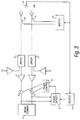
- Figure 3 is a composite diagram showing the two modifications which are required in order to implement the monitoring of an array of antenna elements by injecting a test signal into the array of elements and detecting the signals at the end of the signal paths adjacent the beam former.
- the test signal to be injected into the antenna array is derived from a signal source (16) which is connected to either the switch (15) and hence the signal couplers (14) or else the probe (12).
- the source (16) also sends a test signal to the phase detector where the phase of the test signal is compared with the received signals.
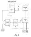
- Fig. 4 shows in more detail how the phase control is carried out by the control circuit 9.
- the same reference numerals are used for the same parts shown in the other drawings as this type of phase correction can be used in all embodiments described above.
- the phase detector (8) receives an output A from the signal path at the beam former and an output B from the monitoring system at the antenna array and compares them to produce an error signal C.
- the error signal C is fed to a look-up table (20) where the value of the error signal results in a specific output signal D being produced which is applied to the phase shifter (10) of the signal path associated with the antenna element being monitored.
- a selector circuit (21) is provided to ensure that the output signal A from the signal path and the phase shifter (10) are the correct ones for the antenna element to be monitored.
- all the signals from the signal paths are supplied to a first switching circuit (22) and the desired signal A is fed to the phase detector circuit (8) under the control of a control circuit (23) which also controls a second switching circuit 24 which directs the output D of the look-up table to the appropriate phase shifter 10.
- the control circuit (23) has a further output which is used to control the switch circuit (15) if used.
- a look-up table allows the use of non-precision phase shifters as the signal required to make a specific phase shifter can be predetermined during initial installation of the antenna array and the calibration thereof so that when the output of the phase detector (8) produces an error signal this is directly converted by the look-up table into the appropriate predetermined signal in order to produce the desired phase shift from that specific phase shifter. Also, the precise pattern formed by the array of antenna elements can be maintained even when the length of the signal path from the beam former (2) to the antenna differs.
Landscapes
- Variable-Direction Aerials And Aerial Arrays (AREA)
Abstract
Description
Claims (11)
- A method of monitoring an antenna array comprising a plurality of antenna elements each of which is connected to one end of a respective signal path, the other ends of which are connected to a beam forming circuit, the method comprising the steps of:-a) selecting one of the elements of the array;b) applying a first signal of known characteristics to said one end of a respective signal path;c) detecting at the other end of the said signal path a second signal resulting from the application of said first signal to said element;d) comparing the detected second signal with the applied first signal whereby to monitor changes in the characteristics of the applied signal due to the signal path; ande) repeating steps a), b) and c) for each element of the array.
- A method of monitoring an antenna array according to claim 1, wherein said second signal is detected by a single detector is located in the near field of the antenna array and visible to all elements of the array.
- A method of monitoring an antenna array according to claim 1, wherein said second signal is detected by a signal coupler is associated with each element and the outputs from the couplers are fed to a selector switch, the output of which is fed to the comparing means.
- A method of monitoring an antenna array according to claim 1, wherein the first signal of known characteristics is a test signal applied when the antenna is not in normal transmission mode.
- A method of monitoring an antenna array according to claim 4, wherein the first signal is applied using a probe located in the near field of the antenna array and visible to all elements of the array.
- A method of monitoring an antenna array according to claim 4, wherein the first signal is applied using a signal coupler associated with each element.
- A method of monitoring an antenna array according to claim 1, wherein the first signal of known characteristics is a signal superimposed on a normal transmission signal.
- A method according to claim 1 and further including the step of adjusting the phase relationship of each path as a result of said comparison in order to maintain a predetermined beam pattern for the antenna.
- A method according to claim 6, wherein the comparision step results in the generation of an error signal which is used to access a stored value in a look-up table.
- In a transmission antenna array comprising a plurality of antenna elements each fed with a respective signal from an amplifier connected to an output from a beam forming circuit, means for monitoring the output of the antenna array elements, and means for controlling the phase of the signal fed to the antenna array element so as to ensure that the output from the antenna corresponds to the desired beam shape, the improvement comprising a single monitoring device and means for causing the single monitoring device to monitor the output from each element in turn.
- In a transmission antenna array comprising a plurality of antenna elements each fed with a respective signal from an amplifier connected to an output from a beam forming circuit, means for monitoring the output of the antenna array elements, and means for controlling the phase of the signal fed to the antenna array element, the improvement comprising a signal coupler associated with each element of the array and a selector switch connected to the signal couplers and to the means for controlling the phase of the signal for selectively connecting one of said signal couplers to the controlling means.
Applications Claiming Priority (2)
| Application Number | Priority Date | Filing Date | Title |
|---|---|---|---|
| US924220 | 1997-09-05 | ||
| US08/924,220 US6046697A (en) | 1997-09-05 | 1997-09-05 | Phase control of transmission antennas |
Publications (2)
| Publication Number | Publication Date |
|---|---|
| EP0901183A2 true EP0901183A2 (en) | 1999-03-10 |
| EP0901183A3 EP0901183A3 (en) | 2000-09-20 |
Family
ID=25449907
Family Applications (1)
| Application Number | Title | Priority Date | Filing Date |
|---|---|---|---|
| EP98305054A Withdrawn EP0901183A3 (en) | 1997-09-05 | 1998-06-26 | Phase control of transmission antennas |
Country Status (4)
| Country | Link |
|---|---|
| US (1) | US6046697A (en) |
| EP (1) | EP0901183A3 (en) |
| CA (1) | CA2243147A1 (en) |
| GB (1) | GB9804000D0 (en) |
Cited By (8)
| Publication number | Priority date | Publication date | Assignee | Title |
|---|---|---|---|---|
| WO2002011237A1 (en) * | 2000-07-31 | 2002-02-07 | Nokia Corporation | Calibration apparatus and method for use with an antenna array |
| FR2814013A1 (en) * | 2000-09-13 | 2002-03-15 | Valeo Electronique | METHOD FOR CALIBRATING A HANDS-FREE ACCESS SYSTEM FOR A MOTOR VEHICLE |
| EP1126544A3 (en) * | 2000-02-16 | 2003-11-19 | The Boeing Company | System for calibrating and characterizing an antenna system and method for characterizing an array of antenna elements |
| WO2009079174A1 (en) * | 2007-12-17 | 2009-06-25 | The Boeing Company | Accurate auto-calibration of phased array antennas |
| WO2009083961A1 (en) * | 2007-12-31 | 2009-07-09 | Elta Systems Ltd | Phased array antenna having integral calibration network and method for measuring calibration ratio thereof |
| GB2467772A (en) * | 2009-02-13 | 2010-08-18 | Socowave Technologies Ltd | Feedback of a digital signal to determine latency mismatch error response of the transceiver signal path of an antenna array element |
| EP3276747A1 (en) * | 2016-07-29 | 2018-01-31 | Rohde & Schwarz GmbH & Co. KG | Calibration systems and methods |
| US10164721B2 (en) | 2016-07-29 | 2018-12-25 | Rohde & Schwarz Gmbh & Co. Kg | Calibration systems and methods |
Families Citing this family (22)
| Publication number | Priority date | Publication date | Assignee | Title |
|---|---|---|---|---|
| SE516535C2 (en) | 1999-10-29 | 2002-01-29 | Allgon Ab | Antenna device switchable between a plurality of configuration modes adapted for use in different operating environments and associated method |
| SE516536C2 (en) * | 1999-10-29 | 2002-01-29 | Allgon Ab | Antenna device switchable between a plurality of configuration states depending on two operating parameters and associated method |
| US6917790B1 (en) | 1999-10-29 | 2005-07-12 | Amc Centurion Ab | Antenna device and method for transmitting and receiving radio waves |
| US7024120B2 (en) * | 2002-03-29 | 2006-04-04 | The United States Of America As Represented By The Secretary Of The Navy | Phase tracking multichannel link |
| DE10237823B4 (en) * | 2002-08-19 | 2004-08-26 | Kathrein-Werke Kg | Antenna array with a calibration device and method for operating such an antenna array |
| DE10237822B3 (en) * | 2002-08-19 | 2004-07-22 | Kathrein-Werke Kg | Calibration device for a switchable antenna array and an associated operating method |
| US20050007273A1 (en) * | 2003-07-11 | 2005-01-13 | The Boeing Company | Method and apparatus for prediction and correction of gain and phase errors in a beacon or payload |
| US7268726B2 (en) * | 2003-07-11 | 2007-09-11 | The Boeing Company | Method and apparatus for correction of quantization-induced beacon beam errors |
| US7274329B2 (en) * | 2003-07-11 | 2007-09-25 | The Boeing Company | Method and apparatus for reducing quantization-induced beam errors by selecting quantized coefficients based on predicted beam quality |
| DE102006041225B4 (en) * | 2006-09-02 | 2008-05-15 | Diehl Bgt Defence Gmbh & Co. Kg | Method and system for averting ground-to-air missiles |
| US7830307B2 (en) * | 2007-04-13 | 2010-11-09 | Andrew Llc | Array antenna and a method of determining an antenna beam attribute |
| US8212716B2 (en) * | 2007-12-31 | 2012-07-03 | Elta Systems Ltd. | System and method for calibration of phased array antenna having integral calibration network in presence of an interfering body |
| JP5612257B2 (en) * | 2008-10-20 | 2014-10-22 | 株式会社Nttドコモ | Multi-antenna measurement method and multi-antenna measurement system |
| US8614644B2 (en) * | 2010-04-22 | 2013-12-24 | The Aerospace Corporation | Systems and methods for protecting a receiving antenna from interference by a transmitting antenna |
| US9209523B2 (en) | 2012-02-24 | 2015-12-08 | Futurewei Technologies, Inc. | Apparatus and method for modular multi-sector active antenna system |
| US9130271B2 (en) * | 2012-02-24 | 2015-09-08 | Futurewei Technologies, Inc. | Apparatus and method for an active antenna system with near-field radio frequency probes |
| US10720702B2 (en) * | 2016-01-08 | 2020-07-21 | National Chung Shan Institute Of Science And Technology | Method and device for correcting antenna phase |
| DE102016212136A1 (en) * | 2016-07-04 | 2018-01-04 | Laird Bochum GmbH | Method and device for determining a distance and vehicle |
| EP3306838B8 (en) * | 2016-10-06 | 2019-06-05 | Rohde & Schwarz GmbH & Co. KG | System and method for testing antenna arrays |
| US10446930B1 (en) | 2018-06-25 | 2019-10-15 | Nxp B.V. | Antenna combination device |
| JP7161822B2 (en) * | 2019-06-07 | 2022-10-27 | 旭化成エレクトロニクス株式会社 | Phase adjustment circuit and phase adjustment method |
| EP3751306B1 (en) * | 2019-06-11 | 2024-04-03 | Rohde & Schwarz GmbH & Co. KG | System and method for testing a radar |
Family Cites Families (14)
| Publication number | Priority date | Publication date | Assignee | Title |
|---|---|---|---|---|
| US4176354A (en) * | 1978-08-25 | 1979-11-27 | The United States Of America As Represented By The Secretary Of The Navy | Phased-array maintenance-monitoring system |
| US4532518A (en) * | 1982-09-07 | 1985-07-30 | Sperry Corporation | Method and apparatus for accurately setting phase shifters to commanded values |
| JPH0785543B2 (en) * | 1988-02-22 | 1995-09-13 | 三菱電機株式会社 | Transmitter / receiver module check confirmation device |
| US5412414A (en) * | 1988-04-08 | 1995-05-02 | Martin Marietta Corporation | Self monitoring/calibrating phased array radar and an interchangeable, adjustable transmit/receive sub-assembly |
| DE69018906T2 (en) * | 1989-09-11 | 1995-08-24 | Nippon Electric Co | Phase controlled group antenna with temperature compensation. |
| NO177475C (en) * | 1990-04-14 | 1995-09-20 | Sel Alcatel Ag | Method and apparatus by antenna |
| US5038146A (en) * | 1990-08-22 | 1991-08-06 | Raytheon Company | Array built in test |
| FR2696553B1 (en) * | 1992-10-01 | 1994-11-25 | Alcatel Espace | Near field antenna calibration method for active antenna. |
| MX9605934A (en) * | 1994-06-03 | 1997-12-31 | Ericsson Telefon Ab L M | CALIBRATION OF AN ANTENNA ARRANGEMENT. |
| US5530449A (en) * | 1994-11-18 | 1996-06-25 | Hughes Electronics | Phased array antenna management system and calibration method |
| EP0762541A3 (en) * | 1995-08-29 | 2000-01-12 | DaimlerChrysler AG | Device for calibrating and testing transmit/receive moduls in an active electronically phased array antenna |
| US5644316A (en) * | 1996-05-02 | 1997-07-01 | Hughes Electronics | Active phased array adjustment using transmit amplitude adjustment range measurements |
| US5784030A (en) * | 1996-06-06 | 1998-07-21 | Hughes Electronics Corporation | Calibration method for satellite communications payloads using hybrid matrices |
| US5771019A (en) * | 1996-09-09 | 1998-06-23 | Hughes Electronics Corporation | Method and system for determining the location of a sense antenna associated with a phased array communication system |
-
1997
- 1997-09-05 US US08/924,220 patent/US6046697A/en not_active Expired - Lifetime
-
1998
- 1998-02-25 GB GBGB9804000.9A patent/GB9804000D0/en not_active Ceased
- 1998-06-26 EP EP98305054A patent/EP0901183A3/en not_active Withdrawn
- 1998-07-15 CA CA002243147A patent/CA2243147A1/en not_active Abandoned
Cited By (17)
| Publication number | Priority date | Publication date | Assignee | Title |
|---|---|---|---|---|
| EP1126544A3 (en) * | 2000-02-16 | 2003-11-19 | The Boeing Company | System for calibrating and characterizing an antenna system and method for characterizing an array of antenna elements |
| WO2002011237A1 (en) * | 2000-07-31 | 2002-02-07 | Nokia Corporation | Calibration apparatus and method for use with an antenna array |
| US6809685B2 (en) | 2000-07-31 | 2004-10-26 | Nokia Corporation | Calibration apparatus and method for use with antenna array |
| FR2814013A1 (en) * | 2000-09-13 | 2002-03-15 | Valeo Electronique | METHOD FOR CALIBRATING A HANDS-FREE ACCESS SYSTEM FOR A MOTOR VEHICLE |
| EP1189302A1 (en) * | 2000-09-13 | 2002-03-20 | Valeo Electronique | Calibration method for a handsfree vehicle acces system |
| US6915122B2 (en) | 2000-09-13 | 2005-07-05 | Valeo Electronique | Method for calibration of a keyless entry system for a motor vehicle |
| US7714775B2 (en) | 2007-12-17 | 2010-05-11 | The Boeing Company | Method for accurate auto-calibration of phased array antennas |
| WO2009079174A1 (en) * | 2007-12-17 | 2009-06-25 | The Boeing Company | Accurate auto-calibration of phased array antennas |
| WO2009083961A1 (en) * | 2007-12-31 | 2009-07-09 | Elta Systems Ltd | Phased array antenna having integral calibration network and method for measuring calibration ratio thereof |
| US8013783B2 (en) | 2007-12-31 | 2011-09-06 | Elta Systems Ltd. | Phased array antenna having integral calibration network and method for measuring calibration ratio thereof |
| AU2008344938B2 (en) * | 2007-12-31 | 2012-09-20 | Elta Systems Ltd | Phased array antenna having integral calibration network and method for measuring calibration ratio thereof |
| GB2467772A (en) * | 2009-02-13 | 2010-08-18 | Socowave Technologies Ltd | Feedback of a digital signal to determine latency mismatch error response of the transceiver signal path of an antenna array element |
| GB2467772B (en) * | 2009-02-13 | 2012-05-02 | Socowave Technologies Ltd | Communication system, network element and method for antenna array calibration |
| EP3276747A1 (en) * | 2016-07-29 | 2018-01-31 | Rohde & Schwarz GmbH & Co. KG | Calibration systems and methods |
| US10148366B2 (en) | 2016-07-29 | 2018-12-04 | Rohde & Schwarz Gmbh & Co. Kg | Calibration systems and methods |
| US10164721B2 (en) | 2016-07-29 | 2018-12-25 | Rohde & Schwarz Gmbh & Co. Kg | Calibration systems and methods |
| US10284306B2 (en) | 2016-07-29 | 2019-05-07 | Rohde & Schwarz Gmbh & Co. Kg | Calibration systems and methods |
Also Published As
| Publication number | Publication date |
|---|---|
| US6046697A (en) | 2000-04-04 |
| CA2243147A1 (en) | 1999-03-05 |
| EP0901183A3 (en) | 2000-09-20 |
| GB9804000D0 (en) | 1998-04-22 |
Similar Documents
| Publication | Publication Date | Title |
|---|---|---|
| US6046697A (en) | Phase control of transmission antennas | |
| US6133868A (en) | System and method for fully self-contained calibration of an antenna array | |
| EP0981836B1 (en) | Method and device for antenna calibration | |
| AU2002337354B2 (en) | Antenna system | |
| US6339399B1 (en) | Antenna array calibration | |
| US4994813A (en) | Antenna system | |
| AU630050B2 (en) | Phased array antenna with temperature compensating capability | |
| CA2203966C (en) | Active phased array adjustment using transmit amplitude adjustment range measurements | |
| AU2002337354A1 (en) | Antenna system | |
| GB2166618A (en) | Monopulse radar equipment | |
| US7054602B2 (en) | Calibrating method and apparatus in a telecommunication system | |
| EP0614577B1 (en) | An apparatus and method for correcting electrical path length phase errors | |
| EP0954053A2 (en) | Array antenna radio communication apparatus | |
| US7315581B2 (en) | Method for power detection of multicarrier signals, radio transmission unit and module for such a unit | |
| JP6431775B2 (en) | Phase detector and satellite repeater | |
| MXPA98006450A (en) | Phase control of transmis antennas | |
| JPH01154604A (en) | Array antenna | |
| JP2504214B2 (en) | Automatic Level Control Method for Micro Satellite Communication Equipment | |
| US20040246068A1 (en) | Coaxial line phase stabilization apparatus and method | |
| EP0793292A1 (en) | An antenna receive calibration arrangement | |
| JP6216190B2 (en) | Phase detector and satellite repeater | |
| JPH01227977A (en) | Phased-array radar equipment | |
| JPH0410994B2 (en) | ||
| JPH02202706A (en) | Array antenna | |
| JPH0425222A (en) | Automatically level controlled system |
Legal Events
| Date | Code | Title | Description |
|---|---|---|---|
| PUAI | Public reference made under article 153(3) epc to a published international application that has entered the european phase |
Free format text: ORIGINAL CODE: 0009012 |
|
| AK | Designated contracting states |
Kind code of ref document: A2 Designated state(s): DE FR GB |
|
| AX | Request for extension of the european patent |
Free format text: AL;LT;LV;MK;RO;SI |
|
| RAP3 | Party data changed (applicant data changed or rights of an application transferred) |
Owner name: NORTEL NETWORKS CORPORATION |
|
| PUAL | Search report despatched |
Free format text: ORIGINAL CODE: 0009013 |
|
| AK | Designated contracting states |
Kind code of ref document: A3 Designated state(s): AT BE CH CY DE DK ES FI FR GB GR IE IT LI LU MC NL PT SE |
|
| AX | Request for extension of the european patent |
Free format text: AL;LT;LV;MK;RO;SI |
|
| RAP1 | Party data changed (applicant data changed or rights of an application transferred) |
Owner name: NORTEL NETWORKS LIMITED |
|
| 17P | Request for examination filed |
Effective date: 20001116 |
|
| AKX | Designation fees paid |
Free format text: DE FR GB |
|
| 17Q | First examination report despatched |
Effective date: 20030320 |
|
| RAP1 | Party data changed (applicant data changed or rights of an application transferred) |
Owner name: NORTEL NETWORKS LIMITED |
|
| STAA | Information on the status of an ep patent application or granted ep patent |
Free format text: STATUS: THE APPLICATION IS DEEMED TO BE WITHDRAWN |
|
| 18D | Application deemed to be withdrawn |
Effective date: 20031001 |