EP0900897A2 - Device for placing finishing strips - Google Patents
Device for placing finishing strips Download PDFInfo
- Publication number
- EP0900897A2 EP0900897A2 EP98111379A EP98111379A EP0900897A2 EP 0900897 A2 EP0900897 A2 EP 0900897A2 EP 98111379 A EP98111379 A EP 98111379A EP 98111379 A EP98111379 A EP 98111379A EP 0900897 A2 EP0900897 A2 EP 0900897A2
- Authority
- EP
- European Patent Office
- Prior art keywords
- holding element
- profile
- end strip
- leg
- strips
- Prior art date
- Legal status (The legal status is an assumption and is not a legal conclusion. Google has not performed a legal analysis and makes no representation as to the accuracy of the status listed.)
- Granted
Links
Images


Classifications
-
- E—FIXED CONSTRUCTIONS
- E04—BUILDING
- E04F—FINISHING WORK ON BUILDINGS, e.g. STAIRS, FLOORS
- E04F19/00—Other details of constructional parts for finishing work on buildings
- E04F19/02—Borders; Finishing strips, e.g. beadings; Light coves
- E04F19/04—Borders; Finishing strips, e.g. beadings; Light coves for use between floor or ceiling and wall, e.g. skirtings
- E04F19/0459—Borders; Finishing strips, e.g. beadings; Light coves for use between floor or ceiling and wall, e.g. skirtings characterised by the fixing method
- E04F19/0463—Plinths fixed by snap-action in a direction perpendicular to the wall
-
- A—HUMAN NECESSITIES
- A47—FURNITURE; DOMESTIC ARTICLES OR APPLIANCES; COFFEE MILLS; SPICE MILLS; SUCTION CLEANERS IN GENERAL
- A47B—TABLES; DESKS; OFFICE FURNITURE; CABINETS; DRAWERS; GENERAL DETAILS OF FURNITURE
- A47B77/00—Kitchen cabinets
- A47B77/02—General layout, e.g. relative arrangement of compartments, working surface or surfaces, supports for apparatus
- A47B77/022—Work tops
-
- E—FIXED CONSTRUCTIONS
- E04—BUILDING
- E04F—FINISHING WORK ON BUILDINGS, e.g. STAIRS, FLOORS
- E04F19/00—Other details of constructional parts for finishing work on buildings
- E04F19/02—Borders; Finishing strips, e.g. beadings; Light coves
- E04F19/04—Borders; Finishing strips, e.g. beadings; Light coves for use between floor or ceiling and wall, e.g. skirtings
- E04F19/045—Hygienic or watertight plinths
-
- E—FIXED CONSTRUCTIONS
- E04—BUILDING
- E04F—FINISHING WORK ON BUILDINGS, e.g. STAIRS, FLOORS
- E04F19/00—Other details of constructional parts for finishing work on buildings
- E04F19/02—Borders; Finishing strips, e.g. beadings; Light coves
- E04F19/04—Borders; Finishing strips, e.g. beadings; Light coves for use between floor or ceiling and wall, e.g. skirtings
- E04F2019/0404—Borders; Finishing strips, e.g. beadings; Light coves for use between floor or ceiling and wall, e.g. skirtings characterised by the material
- E04F2019/0413—Borders; Finishing strips, e.g. beadings; Light coves for use between floor or ceiling and wall, e.g. skirtings characterised by the material of metal
Definitions
- the invention relates to a device for fastening End strips, in particular skirting boards, wall connection strips, Ceiling connection strips, transition strips or Like., With a mounting profile for the end strip.
- the strips and profiles can be made within the scope of the invention Plastic, metal or the like. Material exist. Furthermore can also be strips and profile pieces.
- the invention has for its object a device to create which is simple, fast and aligned fastening of end strips without adjustment difficulties to the respective installation conditions guaranteed without the usual tools.
- the invention solves this problem with a generic one Fastening device in that the mounting profile as a U-shaped border profile for one in the U-recess engaging holding element is formed that the one U-leg on the top of the holding element as a double leg is formed to form an insertion groove, and that in the slot the end strip with a Slide-in spring with the formation of a non-shifting Tongue / groove connection can be inserted or vice versa.
- the mounting profile as a U-shaped border profile for one in the U-recess engaging holding element is formed that the one U-leg on the top of the holding element as a double leg is formed to form an insertion groove, and that in the slot the end strip with a Slide-in spring with the formation of a non-shifting Tongue / groove connection can be inserted or vice versa.
- the end strip an insertion groove for receiving the insertion spring to form a tongue and groove connection.
- the holding element is preferably around a holding plate, a floor covering or Carpeting.
- Holding plate means in the context of the invention for example floor plate, ceiling plate, worktop or Like., In particular also laminate panels, as they are increasing Dimensions as floor and ceiling panels or flooring or ceiling cladding are used. Indeed guaranteed within the scope of the invention, the holding plate to be installed, but also a floor slab to be installed, always a perfect fit of the U-shaped border profile without that drilling, screwing, nailing or gluing work is required are.
- floor slabs for example as a holding plate is always a perfect one in advance as well as dirt and moisture repellent seat of the End strip or the skirting board for a base plate without additional drilling, screwing, nailing or gluing guaranteed.
- the end strip or skirting board only with their insertion spring in the insertion groove the mounting bar and then firmly with the floor slab (s) and after laying them connected to the ground.
- worktops with wall connection strips equip, but also ceiling panels, etc. Always the end strip with the intermediary of the border strip directly connected to the respective holding plate.
- the invention provides that the width of the U-recess of the border profile and the thickness of the holding element with the formation of a slip-proof passport or Clamping seat are coordinated.
- the U-recess but can also or additionally as conical towards the opening tapering recess to be formed perfect fit of the border profile on the edge To ensure the holding element.
- the slot as facing the opening be designed tapering groove and regardless of the insertion spring on the end profile a one-step or form a multi-stage rest seat connection.
- the insertion spring of the end strip from one that can be connected to the end strip e.g. B. lockable spring profile is formed, so not part the end bar is.
- the spring profile as an L-shaped profile formed, one of the L-legs in a receiving slot engages on the underside of the end strip and whose other L-leg horizontally from the end strip protrudes so that it is inserted into the insertion groove of the edging profile to be plugged in.
- the U base at the front of the holding elements as Double leg to form a vertical insertion groove educated.
- this is vertical Insertion groove with a molded or separate insertion spring to form a tongue and groove connection insertable or fixable.
- the mounting profile can also be used as a L-shaped border profile for one of the one L-leg overlapped holding element be formed, the one L-leg as double leg to form an insertion groove is formed and in the slot the end strip with an insertion spring to form a Tongue / groove connection can be inserted.
- the double leg on his an underside associated with the holding element, e.g. B. an adhesive tape or double-sided tape.
- an adhesive tape or double-sided tape can be horizontal or vertical Insertion groove can be realized.
- All of the embodiments enable a subsequent Assembly in the course of a sliding technique. From Another particular advantage is the fact that even at new and consequently working floors no cracking fear because the fastening device according to the invention always with the holding element and consequently with a floor covering, a carpet, a holding plate or the like, is consequently independent of that respective floor, which is, for example can trade a concrete floor.
- the fastening device according to the invention always with the holding element and consequently with a floor covering, a carpet, a holding plate or the like, is consequently independent of that respective floor, which is, for example can trade a concrete floor.
- floor cracks not on the invention Transfer fastening system.
- the mounting profile is U-shaped Socket profile 2 for an engaging in the U-recess 3 Holding element 4 formed.
- the holding element is is a base plate 4 according to the exemplary embodiment, namely laminate board.
- the one U-leg of the Einfberprofils 2 is on the top of the bottom plate 4 as Double leg 5 to form a horizontal Insert groove 6 formed.
- the End strip 1 with an insertion spring 7 with formation a sliding, tongue and groove connection can be inserted or insertable.
- the width of the U-recess 3 of the border profile 2 and the thickness of the bottom plate 4 are under formation a secure fit or a snug fit Voted.
- the U-legs of the U-recess 3 can inside a corrugation or the like. measures to increase friction have what is not shown.
- the slot 6 forms with the insertion spring 7 on the end strip 1 multi-stage rest seat connection, which is only hinted at is.
- the end strip 1 can be assembled as a solid strip are available, in which the Recording slot 10 is incorporated.
- the insertion spring 7 of the end strip 1 of one with the end strip 1 connectable e.g. B. lockable spring profile 8 is formed.
- the spring profile 8 is designed as an L-shaped profile, whose one L-leg 9 in a receiving slot 10 engages at the bottom of the end strip 1 and whose other L-leg 11 horizontally from the end bar 1 cantilevered and in a socket slot 13 of the socket profile or the holding plate 4 engages.
- the end bar 1 points in the area and above the projecting L-leg 11 a recess 12 for gripping over the relevant Holding plate 4 on.
- the U-base 14 is on the End face of the holding element 4 as a double leg 5 under Formation of a vertical insertion groove 6 is formed.
- this insertion groove 6 is also in this embodiment End strip 1 with a molded or separate insertion spring 7 insertable to form a tongue and groove connection or fixable.
- the mounting profile is as one L-shaped border profile 2 for one of the one L-leg overlapped holding element 4 is formed.
- the one L-leg is as a double leg 5 to form one Insert groove 6 formed.
- the End strip 1 with an insertion spring 7 with formation a tongue and groove connection can be inserted.
- the double leg 5 points to its associated with the holding element 4 Underside of an adhesive coating 15, according to the embodiment a double-sided tape. So far an adhesive connection between the L-shaped border profile 2 and the holding element 4.
- a horizontal insertion groove 6 however, a vertical insertion groove can also be realized.
Abstract
Description
Die Erfindung betrifft eine Vorrichtung zum Befestigen von Abschlußleisten, insbesondere von Sockelleisten, Wandanschlußleisten, Deckenanschlußleisten, Übergangsleisten od. dgl., mit einem Montageprofil für die Abschlußleiste. Im Rahmen der Erfindung können die Leisten und Profile aus Kunststoff, Metall od. dgl. Werkstoff bestehen. Außerdem kann es sich auch um Leisten- und Profilstücke handeln.The invention relates to a device for fastening End strips, in particular skirting boards, wall connection strips, Ceiling connection strips, transition strips or Like., With a mounting profile for the end strip. in the The strips and profiles can be made within the scope of the invention Plastic, metal or the like. Material exist. Furthermore can also be strips and profile pieces.
Um eine verdeckte Montage von Abschlußleisten zu erreichen, ist es bekannt, deren Montageprofil mit Bohrungen zu versehen und Schraubverbindungen herzustellen. Auch kennt man das Nageln oder Kleben solcher Montageprofile. Stets sind in diesem Zusammenhang aufwendige Meß- und Montagearbeiten erforderlich, gleichgültig ob mit Dübeln und Schrauben gearbeitet, geklebt oder genagelt wird. Im ersteren Fall muß das Montageprofil in vorgegebenen Abständen durchbohrt werden, im letzteren Fall ist ein unmittelbares Durchnageln des Montageprofils erforderlich. Das gilt auch für die betreffende Wand oder Halteplatte. Regelmäßig genügen bereits leichte im Zuge der Bearbeitung und Montagearbeiten verursachte Maßdifferenzen, die eine ordnungsgemäße Fixierung am Boden, an der Decke oder beispielsweise an einem Arbeitstisch unmöglich machen. So lassen sich unerwünschte Fugenbildung ebenso wenig wie ein windschiefer Verlauf der Abschlußleiste nicht ausschließen. - Hier will die Erfindung Abhilfe schaffen.In order to achieve a concealed installation of end strips, it is known to provide their mounting profile with holes and make screw connections. You also know nailing or gluing such mounting profiles. Always are in this context, complex measuring and assembly work required, regardless of whether working with dowels and screws, is glued or nailed. In the former case pierced the mounting profile at predetermined intervals in the latter case is direct nailing of the mounting profile required. This also applies to the one in question Wall or mounting plate. Regularly are enough slight caused in the course of processing and assembly work Differences in dimensions, the proper fixation on Floor, on the ceiling or, for example, on a work table to make impossible. In this way, unwanted gaps can be formed just as little as a skewed course of the end strip do not exclude. - Here is the invention Remedy.
Der Erfindung liegt die Aufgabe zugrunde, eine Vorrichtung zu schaffen, welche eine einfache, schnelle und ausgerichtete Befestigung von Abschlußleisten ohne Anpassungsschwierigkeiten an die jeweiligen Einbauverhältnisse ohne sonst übliche Hilfsmittel gewährleistet.The invention has for its object a device to create which is simple, fast and aligned fastening of end strips without adjustment difficulties to the respective installation conditions guaranteed without the usual tools.
Diese Aufgabe löst die Erfindung bei einer gattungsgemäßen Befestigungsvorrichtung dadurch, daß das Montageprofil als ein U-förmiges Einfaßprofil für ein in die U-Ausnehmung eingreifendes Halteelement ausgebildet ist, daß der eine U-Schenkel auf der Oberseite des Halteelementes als Doppelschenkel unter Bildung einer Einschubnut ausgebildet ist, und daß in die Einschubnut die Abschlußleiste mit einer Einschubfeder unter Bildung einer verschiebesicheren Nut/Federverbindung einschiebbar ist oder umgekehrt. Umgekehrt meint, daß der eine U-Schenkel auf der Oberseite des Halteelementes auch als Doppelschenkel unter Bildung einer Einschubfeder ausgebildet sein kann und daß die Abschlußleiste eine Einschubnut zur Aufnahme der Einschubfeder unter Bildung einer Nut/Federverbindung aufweise. - Im Rahmen der Erfindung handelt es sich bei dem Halteelement vorzugsweise um eine Halteplatte, einen Bodenbelag oder Teppichboden. Halteplatte meint im Rahmen der Erfindung beispielsweise Bodenplatte, Deckenplatte, Arbeitsplatte od. dgl., insbesondere auch Laminatplatten, wie sie in zunehmendem Maße als Boden- und Deckenplatten bzw. Bodenbelag oder Deckenverkleidung Verwendung finden. Tatsächlich gewährleistet im Rahmen der Erfindung die zu verlegende Halteplatte, aber auch eine zu verlegende Bodenplatte, stets einen einwandfreien Sitz des U-förmigen Einfaßprofils, ohne daß Bohrungs-, Schraub-, Nagel- oder Klebearbeiten erforderlich sind. Denn mit dem Verlegen von beispielsweise Bodenplatten als Halteplatten wird stets vorab ein einwandfreier sowie schmutz- und feuchtigkeitsabweisender Sitz der Abschlußleiste bzw. bei einer Bodenplatte die Sockelleiste ohne zusätzliche Bohr-, Schraub,- Nagel- oder Klebearbeiten gewährleistet. Tatsächlich muß die Abschlußleiste bzw. Sockelleiste lediglich mit ihrer Einschubfeder in die Einschubnut der Montageleiste eingeschoben werden und ist dann fest mit der bzw. den Bodenplatten und nach deren Verlegung mit dem Boden verbunden. - In gleicher Weise lassen sich im Rahmen der Erfindung auch Arbeitsplatten mit Wandanschlußleisten ausrüsten, aber auch Deckenplatten usw.. Stets wird die Abschlußleiste unter Zwischenschaltung der Einfaßleiste unmittelbar mit der jeweiligen Halteplatte verbunden. Folglich wird auch insoweit ein entscheidender Vorteil erreicht, weil die Oberfläche von Boden, Decke, Wand oder Arbeitsplatte nie durch Schrauben, Nägel od. dgl. zerstört wird, die bei eindringender Feuchtigkeit Laminate von ihrer Grundplatte lösen können. Im ganzen wird die Montage von Abdeckleisten erheblich vereinfacht und läßt sich stets schnell und funktionssicher von Laien und folglich Heimwerkern vornehmen. Darüber hinaus ist die Abdeckleiste für beispielsweise Renovierungsarbeiten auch leicht demontierbar und wieder montierbar, und zwar beliebig oft. Von Bedeutung ist ferner die Tatsache, daß sich die erfindungsgemäße Befestigungsvorrichtung aus U-förmigem Einfaßprofil und Abdeckleiste selbst als Bilderrahmen verwirklichen läßt, wenn das Bild mit oder ohne eine abdeckende Glasscheibe von dem U-förmigen Einfaßprofil mit der Abdeckleiste unter Bildung eines Bilderrahmens eingerahmt werden. Grundsätzlich können das Einfaßprofil und die Abdeckleiste aus Metall, Holz oder Kunststoff oder aus einer Kombination dieser Werkstoffe bestehen, wenngleich der Ausführungsform aus Kunststoff wegen ihrer erhöhten Biegeelastizität bevorzugte Bedeutung zukommt.The invention solves this problem with a generic one Fastening device in that the mounting profile as a U-shaped border profile for one in the U-recess engaging holding element is formed that the one U-leg on the top of the holding element as a double leg is formed to form an insertion groove, and that in the slot the end strip with a Slide-in spring with the formation of a non-shifting Tongue / groove connection can be inserted or vice versa. Vice versa thinks that one U-leg on the top of the Holding element also as a double leg to form a Insert spring can be formed and that the end strip an insertion groove for receiving the insertion spring to form a tongue and groove connection. - As part of of the invention, the holding element is preferably around a holding plate, a floor covering or Carpeting. Holding plate means in the context of the invention for example floor plate, ceiling plate, worktop or Like., In particular also laminate panels, as they are increasing Dimensions as floor and ceiling panels or flooring or ceiling cladding are used. Indeed guaranteed within the scope of the invention, the holding plate to be installed, but also a floor slab to be installed, always a perfect fit of the U-shaped border profile without that drilling, screwing, nailing or gluing work is required are. Because with the laying of floor slabs, for example as a holding plate is always a perfect one in advance as well as dirt and moisture repellent seat of the End strip or the skirting board for a base plate without additional drilling, screwing, nailing or gluing guaranteed. In fact, the end strip or skirting board only with their insertion spring in the insertion groove the mounting bar and then firmly with the floor slab (s) and after laying them connected to the ground. - In the same way can be Within the scope of the invention, worktops with wall connection strips equip, but also ceiling panels, etc. Always the end strip with the intermediary of the border strip directly connected to the respective holding plate. Hence a decisive advantage is achieved in this respect, because the surface of the floor, ceiling, wall or worktop never destroyed by screws, nails or the like the laminates of their Can loosen the base plate. On the whole, the assembly of Cover strips considerably simplified and can always fast and reliable by laymen and consequently do-it-yourselfers make. In addition, the cover strip for For example, renovation work can also be easily dismantled and reassembled, as often as you like. Significant is also the fact that the invention Fastening device made of U-shaped border profile and cover strip itself as a picture frame leaves if the picture with or without a covering glass from the U-shaped border profile with the cover strip be framed to form a picture frame. Basically, the border profile and the cover strip made of metal, wood or plastic or a combination these materials exist, although the embodiment made of plastic because of its increased bending elasticity preferred meaning.
Weitere erfindungswesentliche Merkmale sind im folgenden aufgeführt. So sieht die Erfindung vor, daß die Breite der U-Ausnehmung des Einfaßprofils und die Dicke des Halteelementes unter Bildung eines verschiebesicheren Paß- oder Klemmsitzes aufeinander abgestimmt sind. Die U-Ausnehmung kann aber auch oder zusätzlich als sich zur Öffnung hin konisch verjüngende Ausnehmung ausgebildet sein, um einen einwandfreien Sitz des Einfaßprofils randseitig auf dem Halteelement zu gewährleisten. Ferner besteht die Möglichkeit, daß die U-Schenkel der U-Ausnehmung innenseitig Widerhaken, eine Riffelung od. dgl. reibungserhöhende Aufrauhungen oder Beschichtungen aufweisen. Im Rahmen der Erfindung kann auch die Einschubnut als sich zur Öffnung hin verjüngende Nut ausgebildet sein und unabhängig davon mit der Einschubfeder an dem Abschlußprofil eine einstufige oder mehrstufige Rastsitzverbindung bilden. Insbesondere die mehrstufige Rastsitzverbindung ermöglicht eine einwandfreie Anpassung der Abschlußleiste an die jeweiligen Gegebenheiten. - Nach einer abgewandelten Ausführungsform der Erfindung ist vorgesehen, daß die Einschubfeder der Abschlußleiste von einem mit der Abschlußleiste verbindbaren, z. B. verrastbaren Federprofil gebildet ist, also nicht Bestandteil der Abschlußleiste ist. In diesem Fall ist zweckmäßigerweise das Federprofil als L-förmiges Profil ausgebildet, dessen einer L-Schenkel in einem Aufnahmeschlitz an der Unterseite der Abschlußleiste eingreift und dessen anderer L-Schenkel waagerecht aus der Abschlußleiste vorkragt, um also in die Einschubnut des Einfaßprofils eingeschoben bzw. eingesteckt werden zu können. In diesem Zusammenhang kann es vorteilhaft sein, daß die Abschlußleiste im Bereich und oberhalb des vorkragenden L-Schenkels eine Ausnehmung aufweist, damit eine einwandfreie Montage auf bzw. an dem Einfaßprofil gewährleistet ist.Further features essential to the invention are as follows listed. So the invention provides that the width of the U-recess of the border profile and the thickness of the holding element with the formation of a slip-proof passport or Clamping seat are coordinated. The U-recess but can also or additionally as conical towards the opening tapering recess to be formed perfect fit of the border profile on the edge To ensure the holding element. There is also the possibility that the U-legs of the U-recess barb inside, a corrugation or the like. friction-increasing roughening or have coatings. Within the scope of the invention can also insert the slot as facing the opening be designed tapering groove and regardless of the insertion spring on the end profile a one-step or form a multi-stage rest seat connection. Especially the multi-stage click seat connection allows a perfect Adaptation of the end bar to the respective circumstances. - According to a modified embodiment of the Invention is provided that the insertion spring of the end strip from one that can be connected to the end strip, e.g. B. lockable spring profile is formed, so not part the end bar is. In this case expediently the spring profile as an L-shaped profile formed, one of the L-legs in a receiving slot engages on the underside of the end strip and whose other L-leg horizontally from the end strip protrudes so that it is inserted into the insertion groove of the edging profile to be plugged in. In this context it may be advantageous that the end strip in the area and above the protruding L-leg Has recess, so that a perfect installation or is guaranteed on the border profile.
Nach einer abgewandelten Ausführungsform der Erfindung ist die U-Basis an der Stirnseite des Halteelemente als Doppelschenkel unter Bildung einer vertikalen Einschubnut ausgebildet. In diesem Fall ist in diese vertikale Einschubnut die Abschlußleiste mit einer angeformten oder separaten Einschubfeder unter Bildung einer Nut/Federverbindung einschiebbar bzw. fixierbar.According to a modified embodiment of the invention the U base at the front of the holding elements as Double leg to form a vertical insertion groove educated. In this case, this is vertical Insertion groove with a molded or separate insertion spring to form a tongue and groove connection insertable or fixable.
Nach einem Vorschlag der Erfindung, dem selbständige Bedeutung zukommt, kann das Montageprofil aber auch als ein L-förmiges Einfaßprofil für ein von dem einen L-Schenkel übergriffenes Halteelement ausgebildet sein, wobei der eine L-Schenkel als Doppelschenkel unter Bildung einer Einschubnut ausgebildet ist und in die Einschubnut die Abschlußleiste mit einer Einschubfeder unter Bildung einer Nut/Federverbindung einschiebbar ist. Bei dieser abgewandelten Ausführungsform weist der Doppelschenkel auf seine dem Halteelement zugeordneten Unterseite einen Klebebelag, z. B. ein Klebeband oder Doppelklebeband auf. Auch bei dieser Ausführungsform kann eine horizontale oder vertikale Einschubnut verwirklicht sein.According to a proposal of the invention, the self-employed Of importance, the mounting profile can also be used as a L-shaped border profile for one of the one L-leg overlapped holding element be formed, the one L-leg as double leg to form an insertion groove is formed and in the slot the end strip with an insertion spring to form a Tongue / groove connection can be inserted. In this modified Embodiment has the double leg on his an underside associated with the holding element, e.g. B. an adhesive tape or double-sided tape. Also at This embodiment can be horizontal or vertical Insertion groove can be realized.
Sämtliche Ausführungsformen ermöglichen eine nachträgliche Montage im Zuge gleichsam einer Schiebetechnik. Von besonderem Vorteil ist ferner die Tatsache, daß selbst bei neuen und folglich arbeitenden Böden keine Rißbildung zu befürchten ist, weil die erfindungsgemäße Befestigungsvorrichtung stets mit dem Halteelement und folglich mit einem Bodenbelag, einem Teppichboden, einer Halteplatte oder dergleichen gekoppelt ist, folglich unabhängig von dem jeweiligen Boden ist, bei dem es sich beispielsweise um einen Betonboden handeln kann. Jedenfalls werden sich eventuell bildende Bodenrisse nicht auf das erfindungsgemäße Befestigungssystem übertragen.All of the embodiments enable a subsequent Assembly in the course of a sliding technique. From Another particular advantage is the fact that even at new and consequently working floors no cracking fear because the fastening device according to the invention always with the holding element and consequently with a floor covering, a carpet, a holding plate or the like, is consequently independent of that respective floor, which is, for example can trade a concrete floor. Anyway, will possibly forming floor cracks not on the invention Transfer fastening system.
Im folgenden wird die Erfindung anhand einer lediglich ein Ausführungsbeispiel darstellenden Zeichnung näher erläutert; es zeigen:
- Fig. 1
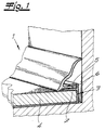
- eine Befestigungsvorrichtung mit Bodenplatte als Halteelement, Einfaßprofil und Sockelleiste als Abschlußleiste ausschnittsweise und in perspektivischer Darstellung,
- Fig. 2
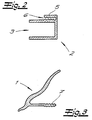
- das Einfaßprofil in Stirnansicht,
- Fig. 3
- das Abschlußprofil bzw. die Sockelleiste in Stirnansicht mit angeformter Einschubfeder,
- Fig. 4
- eine abgewandelte Ausführungsform des Gegenstandes nach Fig. 3 mit L-förmiger Einschubfeder,
- Fig. 5
- die L-förmige Einschubfeder ausschnittsweise und in perspektivischer Darstellung,
- Fig. 6
- eine abgewandelte Ausführungsform des Gegenstandes nach Fig. 4 mit einer von der Abschlußleiste separaten Einschubfeder für einerseits die Abschlußleiste und andererseits das Einfaßprofil,
- Fig. 7
- eine abgewandelte Ausführungsform des Gegenstandes nach Fig. 1 und
- Fig. 8
- eine weitere abgewandelte Ausführungsform des Gegenstandes nach Fig. 1.
- Fig. 1
- a fastening device with a base plate as a holding element, edging profile and skirting board as an end bar in sections and in perspective,
- Fig. 2
- the border profile in front view,
- Fig. 3
- the end profile or the skirting board in front view with molded insertion spring,
- Fig. 4
- 3 with an L-shaped insertion spring,
- Fig. 5
- the L-shaped insertion spring in sections and in perspective,
- Fig. 6
- 4 with a plug-in spring separate from the cover strip for the cover strip on the one hand and the edging profile on the other hand,
- Fig. 7
- a modified embodiment of the object of FIG. 1 and
- Fig. 8
- a further modified embodiment of the object according to FIG. 1.
In den Figuren ist eine Vorrichtung zum Befestigen von Abschlußleisten
1 dargestellt, und zwar mit einem
Montageprofil 2 für die Abschlußleiste 1. Bei der Abschlußleiste
1 handelt es sich nach dem Ausführungsbeispiel um
eine Sockelleiste. Das Montageprofil ist als U-förmiges
Einfaßprofil 2 für ein in die U-Ausnehmung 3 eingreifendes
Halteelement 4 ausgebildet. Bei dem Halteelement handelt es
sich nach dem Ausführungsbeispiel um eine Bodenplatte 4,
nämlich Laminatplatte. Der eine U-Schenkel des
Einfaßprofils 2 ist auf der Oberseite der Bodenplatte 4 als
Doppelschenkel 5 unter Bildung einer horizontalen
Einschubnut 6 ausgebildet. In die Einschubnut 6 ist die
Abschlußleiste 1 mit einer Einschubfeder 7 unter Bildung
einer verschiebesicheren Nut/Federverbindung einschiebbar
bzw. einsteckbar. Die Breite der U-Ausnehmung 3 des Einfaßprofils
2 und die Dicke der Bodenplatte 4 sind unter Bildung
eines verschiebesicheren Paß- oder Klemmsitzes aufeinander
abgestimmt. Die U-Schenkel der U-Ausnehmung 3 können
innenseitig eine Riffelung od. dgl. reibungserhöhende Maßnahmen
aufweisen, was nicht gezeigt ist. Die Einschubnut 6
bildet mit der Einschubfeder 7 an der Abschlußleiste 1 eine
mehrstufige Rastsitzverbindung, die lediglich angedeutet
ist. Die Abschlußleiste 1 kann als montagefertige Massivleiste
zur Verfügung stehen, in der dann bereits der
Aufnahmeschlitz 10 eingearbeitet ist.In the figures there is a device for fastening end strips
1, with a
Nach einer abgewandelten Ausführungsform ist die Einschubfeder
7 der Abschlußleiste 1 von einem mit der Abschlußleiste
1 verbindbaren, z. B. verrastbaren Federprofil 8 gebildet.
Das Federprofil 8 ist als L-förmiges Profil ausgebildet,
dessen einer L-Schenkel 9 in einem Aufnahmeschlitz
10 an der Unterseite der Abschlußleiste 1 eingreift und
dessen anderer L-Schenkel 11 waagerecht aus der Abschlußleiste
1 vorkragt und in einen Einfaßschlitz 13 des Einfaßprofils
bzw. der Halteplatte 4 eingreift. Die Abschlußleiste
1 weist im Bereich und oberhalb des vorkragenden L-Schenkels
11 eine Ausnehmung 12 zum Übergreifen der betreffenden
Halteplatte 4 auf.According to a modified embodiment, the
Nach einer weiteren abgewandelten Ausführungsform, bei
welcher das Montageprofil ebenfalls als ein U-förmiges Einfaßprofil
2 für ein in die U-Ausnehmung 3 eingreifendes
Halteelement 4 ausgebildet ist, ist die U-Basis 14 an der
Stirnseite des Halteelementes 4 als Doppelschenkel 5 unter
Bildung einer vertikalen Einschubnut 6 ausgebildet. In
diese Einschubnut 6 ist auch bei dieser Ausführungsform die
Abschlußleiste 1 mit einer angeformten oder separaten Einschubfeder
7 unter Bildung einer Nut/Federverbindung einschiebbar
bzw. fixierbar. According to a further modified embodiment, at
which also the mounting profile as a
Nach einer anderen Variante ist das Montageprofil als ein
L-förmiges Einfaßprofil 2 für einen von dem einen L-Schenkel
übergriffenes Halteelement 4 ausgebildet. Der eine
L-Schenkel ist als Doppelschenkel 5 unter Bildung einer
Einschubnut 6 ausgebildet. In die Einschubnut 6 ist die
Abschlußleiste 1 mit einer Einschubfeder 7 unter Bildung
einer Nut/Federverbindung einschiebbar. Der Doppelschenkel
5 weist auf seiner dem Halteelement 4 zugeordneten
Unterseite einen Klebebelag 15, nach dem Ausführungsbeispiel
ein Doppelklebeband auf. Insoweit läßt sich also
eine Klebeverbindung zwischen dem L-förmigen Einfaßprofil 2
und dem Halteelement 4 herstellen. Zwar ist nach dem
Ausführungsbeispiel eine horizontale Einschubnut 6 gezeigt,
es läßt sich aber auch eine vertikale Einschubnut verwirklichen.According to another variant, the mounting profile is as one
L-shaped
Claims (13)
Priority Applications (1)
| Application Number | Priority Date | Filing Date | Title |
|---|---|---|---|
| EP01119992A EP1154098B1 (en) | 1997-09-09 | 1998-06-20 | Finishing device with finishing strip, mounting profile and retaining element |
Applications Claiming Priority (2)
| Application Number | Priority Date | Filing Date | Title |
|---|---|---|---|
| DE29716146U DE29716146U1 (en) | 1997-09-09 | 1997-09-09 | Device for fastening end strips |
| DE29716146U | 1997-09-09 |
Related Child Applications (1)
| Application Number | Title | Priority Date | Filing Date |
|---|---|---|---|
| EP01119992A Division EP1154098B1 (en) | 1997-09-09 | 1998-06-20 | Finishing device with finishing strip, mounting profile and retaining element |
Publications (3)
| Publication Number | Publication Date |
|---|---|
| EP0900897A2 true EP0900897A2 (en) | 1999-03-10 |
| EP0900897A3 EP0900897A3 (en) | 1999-06-30 |
| EP0900897B1 EP0900897B1 (en) | 2008-05-21 |
Family
ID=8045727
Family Applications (2)
| Application Number | Title | Priority Date | Filing Date |
|---|---|---|---|
| EP01119992A Expired - Lifetime EP1154098B1 (en) | 1997-09-09 | 1998-06-20 | Finishing device with finishing strip, mounting profile and retaining element |
| EP98111379A Expired - Lifetime EP0900897B1 (en) | 1997-09-09 | 1998-06-20 | Finishing device for walls, ceilings or wall bases, with finishing strip, mounting profile and retaining element |
Family Applications Before (1)
| Application Number | Title | Priority Date | Filing Date |
|---|---|---|---|
| EP01119992A Expired - Lifetime EP1154098B1 (en) | 1997-09-09 | 1998-06-20 | Finishing device with finishing strip, mounting profile and retaining element |
Country Status (6)
| Country | Link |
|---|---|
| US (1) | US6115982A (en) |
| EP (2) | EP1154098B1 (en) |
| AT (2) | ATE287480T1 (en) |
| CA (1) | CA2244071A1 (en) |
| DE (3) | DE29716146U1 (en) |
| PL (1) | PL200819B1 (en) |
Cited By (6)
| Publication number | Priority date | Publication date | Assignee | Title |
|---|---|---|---|---|
| EP1233119A2 (en) | 2001-02-20 | 2002-08-21 | Ernst Rüsch GmbH | Fixing element for cover mouldings |
| EP1359268A2 (en) | 2002-05-04 | 2003-11-05 | Xaver Grünwald GmbH | Device for fixing skirting boards |
| WO2005116364A1 (en) | 2004-05-26 | 2005-12-08 | Neuhofer Franz Jun | Device for fastening a cover strip |
| WO2006105956A1 (en) | 2005-04-05 | 2006-10-12 | Karl Pedross Ag | Device for fastening termination strips |
| EP2549032A1 (en) * | 2011-07-18 | 2013-01-23 | Tode Management BVBA | Covering finish profile for the surface to be covered |
| US8640390B2 (en) | 2010-01-25 | 2014-02-04 | Schlueter-Systems Kg | Decorative strip for showers |
Families Citing this family (48)
| Publication number | Priority date | Publication date | Assignee | Title |
|---|---|---|---|---|
| DE29716146U1 (en) * | 1997-09-09 | 1997-11-20 | Doellken & Co Gmbh W | Device for fastening end strips |
| USD473662S1 (en) | 2001-02-14 | 2003-04-22 | Certainteed Corporation | Detachable lineal for doors and windows |
| US6625941B2 (en) * | 2001-02-14 | 2003-09-30 | Certainteed Corporation | Detachable lineal for doors and windows |
| US6550192B1 (en) * | 2001-02-14 | 2003-04-22 | Richard C. Nelson | Transition molding |
| US7055918B2 (en) * | 2001-07-27 | 2006-06-06 | Lachance James L | Attachment element for joining a backplash to a countertop |
| US6729088B2 (en) | 2002-02-05 | 2004-05-04 | Shannon L. Corr | Positioning jig for installing molding |
| US6918212B1 (en) * | 2002-07-23 | 2005-07-19 | Andy W. Anderson, Sr. | Seamed/seamless fabric wall panel system |
| US20040026679A1 (en) * | 2002-08-01 | 2004-02-12 | Terrels Christopher J. | Post and railing construction |
| US20040206028A1 (en) * | 2002-08-01 | 2004-10-21 | Terrels Christopher J. | Railing system and support assembly |
| US7243473B2 (en) * | 2002-08-06 | 2007-07-17 | Terrels Christopher J | Post assembly and trim ring |
| US6883288B1 (en) * | 2002-09-24 | 2005-04-26 | Todd Harbin | J-channel |
| BE1015275A3 (en) * | 2003-01-07 | 2004-12-07 | Flooring Ind Ltd | Clamp for securing skirting board to wall, has adjustable height between arm and lip to adapt clamp to different floor panel thickness |
| US20050224777A1 (en) * | 2004-04-13 | 2005-10-13 | Terrels Christopher J | Connector fitting for railing components |
| US7712263B1 (en) * | 2004-08-02 | 2010-05-11 | Randall Lippie | Bird repellant device |
| US8640397B2 (en) * | 2005-03-21 | 2014-02-04 | Bird-B-Gone, Inc. | Adjustable bird slope |
| US20060242916A1 (en) * | 2005-05-02 | 2006-11-02 | Carney Timber Company | Edge boards and related assemblies |
| US20060283110A1 (en) * | 2005-06-20 | 2006-12-21 | K & T Stoneworks, Inc. | Secure bracket for rapid installation |
| DE102007002592B3 (en) * | 2007-01-12 | 2008-07-24 | Joecks, Martin, Dipl.-Ing. | Mounting device for mounting skirting board, has retaining section with clamping mechanism and clamping element, between which floor base of edge area is clamped, has actuator comprising adjusting screw |
| US7731160B2 (en) * | 2007-09-28 | 2010-06-08 | Railing Dynamics, Inc. | Post and railing assembly with support bracket covers |
| US20090108719A1 (en) * | 2007-10-26 | 2009-04-30 | Klickit Products, L.L.C. | Apparatus and method for attaching a backsplash to a countertop |
| US8147009B1 (en) * | 2007-11-30 | 2012-04-03 | Rider H Joe | Cabinet component system |
| US20090293392A1 (en) * | 2008-05-22 | 2009-12-03 | Tim Dykstra | Moulding Assembly |
| AT507336B1 (en) | 2008-09-25 | 2010-07-15 | Neuhofer Franz Jun | DEVICE FOR FIXING A FINAL BAR |
| US8079186B2 (en) * | 2008-12-22 | 2011-12-20 | Douglas Williams | Soffit system |
| US8074411B1 (en) | 2009-09-11 | 2011-12-13 | Andrew Jacob Anderson | Fabric wall panel and track |
| PL220426B1 (en) * | 2009-11-26 | 2015-10-30 | Adam Sławomir Galas | Strip mounting set |
| ITMI20111192A1 (en) * | 2011-06-29 | 2012-12-30 | Essea S A S Di Spinelli Antonio | OPENING DEVICE FOR A FURNISHING ELEMENT |
| US20140338276A1 (en) * | 2011-07-11 | 2014-11-20 | Cory Halischuk | Fastening a Ceiling Trim |
| US8813623B2 (en) | 2011-08-22 | 2014-08-26 | Gregory Scott Armacost | Assembly for coping and mounting trim molding |
| TWM424610U (en) * | 2011-11-25 | 2012-03-11 | Hulk Energy Technology Co Ltd | Frame structure of solar energy module (1) |
| WO2013142596A2 (en) * | 2012-03-20 | 2013-09-26 | Rtc Industries, Inc. | Shelf gap spacer device for a merchandise display system |
| US9151061B2 (en) | 2012-10-05 | 2015-10-06 | Fiber Cement Foam Systems Insulation, LLC | Method and a device to attach building trims |
| US9027299B2 (en) * | 2013-07-12 | 2015-05-12 | Joseph Mea | Themed modular ceiling and wall decor kit and system |
| USD919839S1 (en) | 2013-12-19 | 2021-05-18 | VPI Corporation | Wall base with angled top |
| US9303414B1 (en) * | 2014-02-10 | 2016-04-05 | Daryl B. Keiser | Grain bin bolt cover |
| AT515906B1 (en) * | 2014-07-18 | 2016-01-15 | Neuhofer Franz Jun | Device for fastening a finishing strip to a wall |
| USD809676S1 (en) | 2016-02-25 | 2018-02-06 | VPI Corporation | Wall base with groove and curved lower section |
| PL232410B1 (en) * | 2016-04-05 | 2019-06-28 | Adam Galas | Spring-type clamping ring and a set of skirting board with spring-type clamping ring |
| DE202016102498U1 (en) | 2016-05-10 | 2016-05-30 | Engeltech Gmbh | Tool-free end bar and fixture |
| DE102017103313A1 (en) | 2017-02-17 | 2018-08-23 | Kgm Holzerzeugnisse Gmbh | Device for tool-free mounting of a terminal strip |
| US20190119911A1 (en) * | 2017-10-25 | 2019-04-25 | War Bird Manufacturing, Inc. | Bird exclusion device |
| WO2020087156A1 (en) * | 2018-10-29 | 2020-05-07 | Fletcher Donald J | Floor edge moulding with wall-taped mounting and pinched floor retention |
| US10900243B2 (en) * | 2019-05-24 | 2021-01-26 | Terry Koethe | Two-piece trim assembly for siding on buildings |
| US10834915B1 (en) * | 2019-09-05 | 2020-11-17 | Paul Tamulewicz | Avian nesting deterrent |
| DE202020101320U1 (en) | 2020-03-10 | 2021-06-11 | Wolfgang Engel | Mounting clip for skirting boards with locking function on the wall |
| DE202020101330U1 (en) | 2020-03-11 | 2021-06-15 | Wolfgang Engel | Mounting clip for skirting boards with locking function on the floor covering |
| DE202020102369U1 (en) | 2020-04-28 | 2020-05-29 | Hilmar Kusmierz | Base profile |
| RU203441U1 (en) * | 2021-01-21 | 2021-04-05 | Александр Михайлович Кузнецов | Skirting board |
Citations (8)
| Publication number | Priority date | Publication date | Assignee | Title |
|---|---|---|---|---|
| DE2110312A1 (en) * | 1971-03-04 | 1972-09-14 | Zech, Klaus, 2300 Kiel | Plaster and screed gauge type Kiel as building element and skirting board |
| DE2123154A1 (en) * | 1971-05-11 | 1972-11-16 | Fa. Wilhelm Schade, 5970 Plettenberg | Device for covering the edges of rooms |
| GB2115692A (en) * | 1981-09-02 | 1983-09-14 | Holden Hydroman Limited | Carpet fasteners |
| GB2194567A (en) * | 1986-08-30 | 1988-03-09 | Geoffrey Stephen Merry | A draught-proofing device |
| GB2227935A (en) * | 1989-02-10 | 1990-08-15 | Colin Stephen Pownall | Floor-covering edge seal |
| US5079880A (en) * | 1990-06-15 | 1992-01-14 | Eugene Reid | Trim for covering and securing dry wall adjacent to surrounding portion of a bathtub or shower stall |
| GB2253222A (en) * | 1991-02-27 | 1992-09-02 | Austin Charles Murphy | Tile trim |
| DE9421899U1 (en) * | 1994-11-09 | 1997-02-06 | Alfer Aluminium Gmbh | Joint covering device |
Family Cites Families (10)
| Publication number | Priority date | Publication date | Assignee | Title |
|---|---|---|---|---|
| BE663722A (en) * | 1951-01-28 | 1900-01-01 | ||
| US3007213A (en) * | 1955-02-14 | 1961-11-07 | Colotrym Company | Junction molding |
| CA898481A (en) * | 1969-12-08 | 1972-04-25 | M. Harby Bernard | Wall base member |
| US3667177A (en) * | 1970-05-08 | 1972-06-06 | Elmer G Biela | Molding joints and universal molding members therefor |
| US4385850A (en) * | 1979-05-08 | 1983-05-31 | Spacetrekker Products Limited | Device for joining panels edge-to-edge |
| FR2660348B1 (en) * | 1990-03-30 | 1992-07-31 | Tomecanic Sa | PROFILE IN PARTICULAR FOR COMPENSATING FOR MOVEMENTS RELATING TO A FLOOR COVERING IN RELATION TO AN ADJACENT WALL. |
| CA2138071A1 (en) * | 1994-12-14 | 1996-06-15 | Helmut Schmidt | Multi part plastic lineal |
| US5836113A (en) * | 1997-04-25 | 1998-11-17 | Douglass Bachman | System and method of securing and finishing exterior siding panels |
| US5829206A (en) * | 1997-04-25 | 1998-11-03 | Douglass Bachman | Top panel snap-in trim for exterior siding |
| DE29716146U1 (en) * | 1997-09-09 | 1997-11-20 | Doellken & Co Gmbh W | Device for fastening end strips |
-
1997
- 1997-09-09 DE DE29716146U patent/DE29716146U1/en not_active Expired - Lifetime
-
1998
- 1998-06-20 EP EP01119992A patent/EP1154098B1/en not_active Expired - Lifetime
- 1998-06-20 EP EP98111379A patent/EP0900897B1/en not_active Expired - Lifetime
- 1998-06-20 AT AT01119992T patent/ATE287480T1/en not_active IP Right Cessation
- 1998-06-20 DE DE59812505T patent/DE59812505D1/en not_active Expired - Lifetime
- 1998-06-20 DE DE59814234T patent/DE59814234D1/en not_active Expired - Lifetime
- 1998-06-20 AT AT98111379T patent/ATE396312T1/en not_active IP Right Cessation
- 1998-07-03 PL PL327221A patent/PL200819B1/en not_active IP Right Cessation
- 1998-09-04 CA CA002244071A patent/CA2244071A1/en not_active Abandoned
- 1998-09-09 US US09/149,963 patent/US6115982A/en not_active Expired - Fee Related
Patent Citations (8)
| Publication number | Priority date | Publication date | Assignee | Title |
|---|---|---|---|---|
| DE2110312A1 (en) * | 1971-03-04 | 1972-09-14 | Zech, Klaus, 2300 Kiel | Plaster and screed gauge type Kiel as building element and skirting board |
| DE2123154A1 (en) * | 1971-05-11 | 1972-11-16 | Fa. Wilhelm Schade, 5970 Plettenberg | Device for covering the edges of rooms |
| GB2115692A (en) * | 1981-09-02 | 1983-09-14 | Holden Hydroman Limited | Carpet fasteners |
| GB2194567A (en) * | 1986-08-30 | 1988-03-09 | Geoffrey Stephen Merry | A draught-proofing device |
| GB2227935A (en) * | 1989-02-10 | 1990-08-15 | Colin Stephen Pownall | Floor-covering edge seal |
| US5079880A (en) * | 1990-06-15 | 1992-01-14 | Eugene Reid | Trim for covering and securing dry wall adjacent to surrounding portion of a bathtub or shower stall |
| GB2253222A (en) * | 1991-02-27 | 1992-09-02 | Austin Charles Murphy | Tile trim |
| DE9421899U1 (en) * | 1994-11-09 | 1997-02-06 | Alfer Aluminium Gmbh | Joint covering device |
Cited By (10)
| Publication number | Priority date | Publication date | Assignee | Title |
|---|---|---|---|---|
| EP1233119A2 (en) | 2001-02-20 | 2002-08-21 | Ernst Rüsch GmbH | Fixing element for cover mouldings |
| EP1233119A3 (en) * | 2001-02-20 | 2002-12-18 | Ernst Rüsch GmbH | Fixing element for cover mouldings |
| DE10107864C2 (en) * | 2001-02-20 | 2003-06-12 | Ernst Ruesch Gmbh | Holding element for cover strips |
| US6643987B2 (en) | 2001-02-20 | 2003-11-11 | Ernst Rüsch GmbH | Supporting element for cover strips |
| EP1359268A2 (en) | 2002-05-04 | 2003-11-05 | Xaver Grünwald GmbH | Device for fixing skirting boards |
| WO2005116364A1 (en) | 2004-05-26 | 2005-12-08 | Neuhofer Franz Jun | Device for fastening a cover strip |
| WO2006105956A1 (en) | 2005-04-05 | 2006-10-12 | Karl Pedross Ag | Device for fastening termination strips |
| US7594368B2 (en) | 2005-04-05 | 2009-09-29 | Karl Pedross Ag | Device for fastening termination strips |
| US8640390B2 (en) | 2010-01-25 | 2014-02-04 | Schlueter-Systems Kg | Decorative strip for showers |
| EP2549032A1 (en) * | 2011-07-18 | 2013-01-23 | Tode Management BVBA | Covering finish profile for the surface to be covered |
Also Published As
| Publication number | Publication date |
|---|---|
| EP0900897A3 (en) | 1999-06-30 |
| US6115982A (en) | 2000-09-12 |
| PL327221A1 (en) | 1999-03-15 |
| EP0900897B1 (en) | 2008-05-21 |
| DE29716146U1 (en) | 1997-11-20 |
| DE59812505D1 (en) | 2005-02-24 |
| DE59814234D1 (en) | 2008-07-03 |
| EP1154098B1 (en) | 2005-01-19 |
| ATE396312T1 (en) | 2008-06-15 |
| CA2244071A1 (en) | 1999-03-09 |
| EP1154098A3 (en) | 2002-01-09 |
| ATE287480T1 (en) | 2005-02-15 |
| PL200819B1 (en) | 2009-02-27 |
| EP1154098A2 (en) | 2001-11-14 |
Similar Documents
| Publication | Publication Date | Title |
|---|---|---|
| EP0900897A2 (en) | Device for placing finishing strips | |
| DE69434534T2 (en) | Floor seal for laminate flooring | |
| DE4215273C2 (en) | Covering for covering floor, wall and / or ceiling surfaces, in particular in the manner of a belt floor | |
| DE202007016585U1 (en) | Profile rail system | |
| WO2010079125A1 (en) | Profile system for a sliding door | |
| DE2853092A1 (en) | FOOTBOARD FIXABLE TO A WALL WITH A BRACKET | |
| DE2715211A1 (en) | Combined skirting board and electric wire conduit - comprises a resilient holding strip fixed to the wall and an inverted U=profile slipped over it | |
| EP0078905B1 (en) | Covering-frame for cladding a wall opening for a door or the like | |
| DE2553185A1 (en) | Floor or wall finish end sealing rail - formed as L:sectioned angled unit with shorter sealing and longer fixing shank | |
| WO2009006926A1 (en) | 45° wall panel concept | |
| DE3202833C2 (en) | Cladding for a frame of a house or room door or the like fastened in a wall opening | |
| DE202004018996U1 (en) | Edging strip for worktops has fixing arm which is embedded in sealant, ceramic top being fitted over this and front of strip having groove, into which ceramic strip is fitted | |
| EP0812045B1 (en) | Cable duct for rooms inside buildings | |
| DE2022222A1 (en) | Nailless skirting board | |
| DE19849264A1 (en) | Shower or bathtub partition | |
| DE3700201C2 (en) | ||
| AT10283U1 (en) | ARRANGEMENT FOR COVERING A CORNER BAR | |
| EP3293323A1 (en) | Mounting system for floor pedestal or skirting board | |
| EP0727544A1 (en) | Device for stair reconstruction | |
| DE4141289A1 (en) | Skirting strip for panel wall or ceiling - comprises fastening section with tongue and intermediate and trim sections | |
| AT395633B (en) | Fastening of an, in particular, wooden covering panel on a metallic door frame or the like | |
| DE4442367C1 (en) | Plasterboard fitting aid for building work | |
| DE19835204B4 (en) | Fastening strap and wooden beam construction with fastening strap | |
| DE202019105353U1 (en) | Fastening profile for fastening a decorative strip to a wall | |
| DE10246968A1 (en) | Step edge profile has housing provided on horizontal step component to incorporate floor tile, and for tension and compression resistant gap-free joining housing has connecting slot conforming to connecting tongue on tile |
Legal Events
| Date | Code | Title | Description |
|---|---|---|---|
| PUAI | Public reference made under article 153(3) epc to a published international application that has entered the european phase |
Free format text: ORIGINAL CODE: 0009012 |
|
| AK | Designated contracting states |
Kind code of ref document: A2 Designated state(s): AT BE CH DE ES FR GB IT LI LU NL |
|
| AX | Request for extension of the european patent |
Free format text: AL;LT;LV;MK;RO;SI |
|
| PUAL | Search report despatched |
Free format text: ORIGINAL CODE: 0009013 |
|
| AK | Designated contracting states |
Kind code of ref document: A3 Designated state(s): AT BE CH CY DE DK ES FI FR GB GR IE IT LI LU MC NL PT SE |
|
| AX | Request for extension of the european patent |
Free format text: AL;LT;LV;MK;RO;SI |
|
| 17P | Request for examination filed |
Effective date: 19991126 |
|
| AKX | Designation fees paid |
Free format text: AT BE CH DE ES FR GB IT LI LU NL |
|
| 17Q | First examination report despatched |
Effective date: 20000703 |
|
| RIN1 | Information on inventor provided before grant (corrected) |
Inventor name: MEYER ZU DREWER, JENS Inventor name: DR. MUELLER, HERBERT Inventor name: WELLERDICK, NORBERT Inventor name: LINDENBERG, KLAUS |
|
| APBX | Invitation to file observations in appeal sent |
Free format text: ORIGINAL CODE: EPIDOSNOBA2E |
|
| APBZ | Receipt of observations in appeal recorded |
Free format text: ORIGINAL CODE: EPIDOSNOBA4E |
|
| APBT | Appeal procedure closed |
Free format text: ORIGINAL CODE: EPIDOSNNOA9E |
|
| APAA | Appeal reference recorded |
Free format text: ORIGINAL CODE: EPIDOS REFN |
|
| APAF | Appeal reference modified |
Free format text: ORIGINAL CODE: EPIDOSCREFNE |
|
| 17Q | First examination report despatched |
Effective date: 20000703 |
|
| 17Q | First examination report despatched |
Effective date: 20000703 |
|
| GRAP | Despatch of communication of intention to grant a patent |
Free format text: ORIGINAL CODE: EPIDOSNIGR1 |
|
| RTI1 | Title (correction) |
Free format text: FINISHING DEVICE FOR WALLS, CEILINGS OR WALL BASES, WITH FINISHING STRIP, MOUNTING PROFILE AND RETAINING ELEMENT |
|
| GRAS | Grant fee paid |
Free format text: ORIGINAL CODE: EPIDOSNIGR3 |
|
| GRAA | (expected) grant |
Free format text: ORIGINAL CODE: 0009210 |
|
| AK | Designated contracting states |
Kind code of ref document: B1 Designated state(s): AT BE CH DE ES FR GB IT LI LU NL |
|
| REG | Reference to a national code |
Ref country code: GB Ref legal event code: FG4D Free format text: NOT ENGLISH |
|
| REG | Reference to a national code |
Ref country code: CH Ref legal event code: EP |
|
| REF | Corresponds to: |
Ref document number: 59814234 Country of ref document: DE Date of ref document: 20080703 Kind code of ref document: P |
|
| PGFP | Annual fee paid to national office [announced via postgrant information from national office to epo] |
Ref country code: CH Payment date: 20080623 Year of fee payment: 11 |
|
| REG | Reference to a national code |
Ref country code: CH Ref legal event code: NV Representative=s name: KELLER & PARTNER PATENTANWAELTE AG |
|
| PGFP | Annual fee paid to national office [announced via postgrant information from national office to epo] |
Ref country code: AT Payment date: 20080624 Year of fee payment: 11 |
|
| PG25 | Lapsed in a contracting state [announced via postgrant information from national office to epo] |
Ref country code: ES Free format text: LAPSE BECAUSE OF FAILURE TO SUBMIT A TRANSLATION OF THE DESCRIPTION OR TO PAY THE FEE WITHIN THE PRESCRIBED TIME-LIMIT Effective date: 20080901 |
|
| NLV1 | Nl: lapsed or annulled due to failure to fulfill the requirements of art. 29p and 29m of the patents act | ||
| PG25 | Lapsed in a contracting state [announced via postgrant information from national office to epo] |
Ref country code: NL Free format text: LAPSE BECAUSE OF FAILURE TO SUBMIT A TRANSLATION OF THE DESCRIPTION OR TO PAY THE FEE WITHIN THE PRESCRIBED TIME-LIMIT Effective date: 20080521 |
|
| BERE | Be: lapsed |
Owner name: W. DOLLKEN & CO. G.M.B.H. Effective date: 20080630 |
|
| PLBE | No opposition filed within time limit |
Free format text: ORIGINAL CODE: 0009261 |
|
| STAA | Information on the status of an ep patent application or granted ep patent |
Free format text: STATUS: NO OPPOSITION FILED WITHIN TIME LIMIT |
|
| PG25 | Lapsed in a contracting state [announced via postgrant information from national office to epo] |
Ref country code: BE Free format text: LAPSE BECAUSE OF NON-PAYMENT OF DUE FEES Effective date: 20080630 |
|
| 26N | No opposition filed |
Effective date: 20090224 |
|
| GBPC | Gb: european patent ceased through non-payment of renewal fee |
Effective date: 20080821 |
|
| PG25 | Lapsed in a contracting state [announced via postgrant information from national office to epo] |
Ref country code: IT Free format text: LAPSE BECAUSE OF FAILURE TO SUBMIT A TRANSLATION OF THE DESCRIPTION OR TO PAY THE FEE WITHIN THE PRESCRIBED TIME-LIMIT Effective date: 20080521 |
|
| PG25 | Lapsed in a contracting state [announced via postgrant information from national office to epo] |
Ref country code: GB Free format text: LAPSE BECAUSE OF NON-PAYMENT OF DUE FEES Effective date: 20080821 |
|
| REG | Reference to a national code |
Ref country code: CH Ref legal event code: PL |
|
| PG25 | Lapsed in a contracting state [announced via postgrant information from national office to epo] |
Ref country code: LI Free format text: LAPSE BECAUSE OF NON-PAYMENT OF DUE FEES Effective date: 20090630 Ref country code: CH Free format text: LAPSE BECAUSE OF NON-PAYMENT OF DUE FEES Effective date: 20090630 |
|
| PG25 | Lapsed in a contracting state [announced via postgrant information from national office to epo] |
Ref country code: LU Free format text: LAPSE BECAUSE OF NON-PAYMENT OF DUE FEES Effective date: 20080620 Ref country code: AT Free format text: LAPSE BECAUSE OF NON-PAYMENT OF DUE FEES Effective date: 20090620 |
|
| REG | Reference to a national code |
Ref country code: FR Ref legal event code: ST Effective date: 20110617 |
|
| PG25 | Lapsed in a contracting state [announced via postgrant information from national office to epo] |
Ref country code: FR Free format text: LAPSE BECAUSE OF NON-PAYMENT OF DUE FEES Effective date: 20080721 |
|
| PGFP | Annual fee paid to national office [announced via postgrant information from national office to epo] |
Ref country code: DE Payment date: 20130708 Year of fee payment: 16 |
|
| REG | Reference to a national code |
Ref country code: DE Ref legal event code: R119 Ref document number: 59814234 Country of ref document: DE |
|
| REG | Reference to a national code |
Ref country code: DE Ref legal event code: R119 Ref document number: 59814234 Country of ref document: DE Effective date: 20150101 |
|
| PG25 | Lapsed in a contracting state [announced via postgrant information from national office to epo] |
Ref country code: DE Free format text: LAPSE BECAUSE OF NON-PAYMENT OF DUE FEES Effective date: 20150101 |