EP0900757A2 - Device for braking and delivering overlapping signatures - Google Patents
Device for braking and delivering overlapping signatures Download PDFInfo
- Publication number
- EP0900757A2 EP0900757A2 EP98116410A EP98116410A EP0900757A2 EP 0900757 A2 EP0900757 A2 EP 0900757A2 EP 98116410 A EP98116410 A EP 98116410A EP 98116410 A EP98116410 A EP 98116410A EP 0900757 A2 EP0900757 A2 EP 0900757A2
- Authority
- EP
- European Patent Office
- Prior art keywords
- transport system
- signatures
- speed
- hold
- conveyor
- Prior art date
- Legal status (The legal status is an assumption and is not a legal conclusion. Google has not performed a legal analysis and makes no representation as to the accuracy of the status listed.)
- Withdrawn
Links
Images

Classifications
-
- B—PERFORMING OPERATIONS; TRANSPORTING
- B65—CONVEYING; PACKING; STORING; HANDLING THIN OR FILAMENTARY MATERIAL
- B65H—HANDLING THIN OR FILAMENTARY MATERIAL, e.g. SHEETS, WEBS, CABLES
- B65H29/00—Delivering or advancing articles from machines; Advancing articles to or into piles
- B65H29/66—Advancing articles in overlapping streams
- B65H29/6609—Advancing articles in overlapping streams forming an overlapping stream
- B65H29/6618—Advancing articles in overlapping streams forming an overlapping stream upon transfer from a first conveyor to a second conveyor advancing at slower speed
-
- B—PERFORMING OPERATIONS; TRANSPORTING
- B65—CONVEYING; PACKING; STORING; HANDLING THIN OR FILAMENTARY MATERIAL
- B65H—HANDLING THIN OR FILAMENTARY MATERIAL, e.g. SHEETS, WEBS, CABLES
- B65H29/00—Delivering or advancing articles from machines; Advancing articles to or into piles
- B65H29/12—Delivering or advancing articles from machines; Advancing articles to or into piles by means of the nip between two, or between two sets of, moving tapes or bands or rollers
-
- B—PERFORMING OPERATIONS; TRANSPORTING
- B65—CONVEYING; PACKING; STORING; HANDLING THIN OR FILAMENTARY MATERIAL
- B65H—HANDLING THIN OR FILAMENTARY MATERIAL, e.g. SHEETS, WEBS, CABLES
- B65H29/00—Delivering or advancing articles from machines; Advancing articles to or into piles
- B65H29/68—Reducing the speed of articles as they advance
-
- B—PERFORMING OPERATIONS; TRANSPORTING
- B65—CONVEYING; PACKING; STORING; HANDLING THIN OR FILAMENTARY MATERIAL
- B65H—HANDLING THIN OR FILAMENTARY MATERIAL, e.g. SHEETS, WEBS, CABLES
- B65H2404/00—Parts for transporting or guiding the handled material
- B65H2404/20—Belts
- B65H2404/26—Particular arrangement of belt, or belts
- B65H2404/261—Arrangement of belts, or belt(s) / roller(s) facing each other for forming a transport nip
- B65H2404/2611—Arrangement of belts, or belt(s) / roller(s) facing each other for forming a transport nip forming curved transport path
-
- B—PERFORMING OPERATIONS; TRANSPORTING
- B65—CONVEYING; PACKING; STORING; HANDLING THIN OR FILAMENTARY MATERIAL
- B65H—HANDLING THIN OR FILAMENTARY MATERIAL, e.g. SHEETS, WEBS, CABLES
- B65H2513/00—Dynamic entities; Timing aspects
- B65H2513/20—Acceleration or deceleration
-
- B—PERFORMING OPERATIONS; TRANSPORTING
- B65—CONVEYING; PACKING; STORING; HANDLING THIN OR FILAMENTARY MATERIAL
- B65H—HANDLING THIN OR FILAMENTARY MATERIAL, e.g. SHEETS, WEBS, CABLES
- B65H2701/00—Handled material; Storage means
- B65H2701/10—Handled articles or webs
- B65H2701/13—Parts concerned of the handled material
- B65H2701/131—Edges
- B65H2701/1313—Edges trailing edge
Definitions
- the present invention relates to printing machines, in particular to a Device for braking the signatures in the folding section of a printing press.
- a continuous paper web is changed from one through one Number of processing units, such as printing units, dryers, cooling units, Slitters, folders, stackers, packetizers, and platen rollers to make one to produce a printed product.
- processing units such as printing units, dryers, cooling units, Slitters, folders, stackers, packetizers, and platen rollers.
- signatures When the web has been cut, it becomes resulting products referred to as signatures.
- the folder often guides them Signatures of the subsequent processing units to faster than they from this can be processed. Therefore it is necessary to speed up the signatures to reduce. It can also be advantageous to have the signatures scaled Bring arrangement, the top of a signature the rear edge of the previous signature overlaps.
- Known methods and devices for braking signatures have Bucket wheels as known from US 5,112,033, US 5,180,160 and US 4,925,179 which are mentioned here for reference.
- signatures are created using a Transfer the bucket wheel from a folder to a delivery transport system.
- the Paddle wheel has a large number of blades that hold the pockets form signatures coming from the folders while the paddle wheel is rotating.
- the signatures can be removed from the paddle wheel by a scraper and for example applied to a conveyor.
- the use of Paddle wheels have problems such as marking, dog ears and Damage caused by the appearance of the signature in the pocket base.
- the object of the invention is a device that brakes the signatures and transferred into a scaly formation.
- this object is achieved in that a tape system for recording of signatures from the folder increases the speed of the signatures; a first transport system lying next to the conveyor system is provided, which the Signatures from this takes over, the first transport system being a slower one Has speed than the belt system; one above the first transport system rotatably mounted first hold-down wheel in rolling contact with it, which the signatures brings up the speed of the first conveyor belt; a second transport system attached to and downstream of the first transport system to the signatures of this to take over, with the second transport system running at a lower speed than that has the first and a second hold-down wheel in rolling contact with it, which is rotatably mounted above the second transport system, and the second Hold down the signatures on the speed of the second transport system brings.
- the device described in the invention cut and folded are Signatures laid out and brought into a scaled formation.
- the overlap distance can run in successive steps.
- the device applies a tape and Roller system, conveyor belts, hold-down wheels and track drives.
- According to the present invention can convert the signatures from one folder to one Conveyor system can be transported without entering a paddle wheel. That way a scaled delivery with conveyor belts and hold-down wheels can be achieved without Use of a paddle wheel or a delay device, the cost of which would exclude certain applications.
- the signatures are, for example, by a Belt transport system transported from the folder to the conveyor system.
- the signatures are placed on a conveyor belt which runs slower than the belt transport system.
- the signatures can be touched by hold-down wheels and in contact with the conveyor belt to be brought. This way, the signature is slowed down to match the slow moving conveyor belt to be transported.
- a number of conveyor belts and hold-down wheels can be used to achieve the desired amount of braking can be used to achieve discrete braking levels.
- Such a tiered one Braking can help achieve an abrupt braking, otherwise the signatures would be damaged and smearing would occur. If one too large deceleration is aimed at using only one Holding wheel / conveyor system combination, the signature can be marked or damaged become.
- Connecting several hold-down wheels / conveyor belt combinations in series one Braking and desquamation can be achieved.
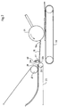
- Fig. 1 shows a former plate 2 of a folder of a printing press, the one has sheet 1 guided and folded over it.
- a first pair of pull rollers 3 around the web 1 coming from the former plate 2 to record.
- a second pair of draw rollers 4 can subsequently, in addition to the Pull roller pair 3 may be arranged to facilitate the handling of the web 1 while this is guided over the former plate 2.
- cutting cylinders 11.1 and 11.2 are arranged to receive the web 1 and separate individual signatures 10 from this.
- the signatures pass through the cutting cylinders 11.1 and 11.2 to the belt system 20.
- the Banding system 20 consists, for example, of belts 23 and 24.
- Belt 23 forms one closed loop around the rollers 25.1, 25.2 and 25.3, while the belt 24 a closed loop around the rollers 26.1, 26.2, 26.3, 26.4 and the rollers 27.1 and 27.2 forms.
- the roller 25.1 attached below and laterally from the center line of the folded web 1, which over the Funnel nose 2.1 of the former plate 2 and the pairs of draw rollers 3 and 4 runs.
- the Roll 27.1 is below and laterally offset against the direction of the rolls 25.1 seen from the center line of the folded web 1, arranged.
- the Rolls 25.1 and 27.1 open a belt funnel 21.
- the rollers 26.1 to 26.4 are arranged such that they form a curved path that the orientation of bands 23 and 24 from vertical to corresponding horizontal position.
- the band 23 passes through a loop on the inside Rollers 25, 25.1, 25.2, 25.3 facing, the path of the outside of the belt 23 through the arcuate arrangement of the rollers 26.1 to 26.4 is influenced.
- Volume 24 passes through a loop with rollers 26.1 to 26.4 and rollers 27.1, 27.2 on the inside the loop. Both belts 23 and 24 follow the curved roller path 26. Die Belts 23 and 24 form a belt exit 29, the belt 23 around the rollers 25.2 and the belt 24 runs around the rollers 27.2.
- the belt exit 29 is mounted next to a first transport system 30 which, for. B. covers a conveying path around the deflection rollers 32.1 and 32.2.
- the signature 10 happens the belt exit 29 directly to the conveyor belt 30 without, for example, in a paddle wheel to enter.
- Such a device prevents e.g. B. the formation of dog ears and that Damaging the signatures, often with the use of paddle wheels goes along.
- the conveyor belt 30 is correspondingly mounted horizontally and includes it assigned hold-down wheel 31.
- the hold-down wheel 31 is above the surface of the Conveyor belt 30 attached.
- the hold-down wheel 31 can, for example, be one Number of coaxially arranged idlers, which are spaced from each other over the Width of the conveyor belt 30 are attached.
- the hold-down wheel 31 is such at the Frame of the printing machine attached that it is possible for it to turn around the axis turn, which is perpendicular to the direction of transport of the conveyor belt 30.
- a second transport system Adjacent to the end of the conveyor belt 30, opposite the belt exit 29 (i.e. downstream of the conveyor belt 30) is a second transport system in the form of a Conveyor belt 33 attached, which a conveyor path around the deflection rollers 35.1 and 35.2 forms.
- the conveyor belts 30 and 33 are opposite each other, so that the Conveyor belt 33 continues the way from the conveyor belt 30.
- Similar to the hold-down wheel 31 the conveyor belt 30 is a second hold-down wheel 34 on the upper surface of the second Transport system 33 attached.
- the hold-down wheel 34 can be placed in any suitable position be attached along the conveyor path on which the hold-down wheel 34 just fits. It can be beneficial, more than one set of hold-down wheels a single Assign transport system.
- the arrangement of the conveyor belt ends together can be carried out such. B. by the transport system 36 attached downstream of the end of the transport system 33 is done.
- the transport system 36 creates a conveyor path around the deflection rollers 38 and 38.1 (not shown) back.
- a web 1 which has been printed and cooled, passes through the printing units and other operating units up to the folding station of the printing press.
- the folder consists of the former plate 2, as shown in Fig. 1.
- the web 1 is guided over the former plate 2 in such a way that it is half-folded along the length.
- the former plate 2 has a corresponding triangular shape.
- the web 1 is fed to the former plate 2 at its tip, the former plate 2 having approximately the same width as the web 1.
- the former plate 2 steadily decreases in width down to the funnel nose 2.1 of the former plate 2.
- the web 1 passes the former plate 2, it is folded in half, which is facilitated by the shape of the former nose 2, the former 2.1 helping to form the main fold line along the web 1.
- the web 1 leaves the former plate 2 and enters a set of draw rollers 3.
- the web 1, which passes the hopper and has been longitudinally folded by it, can also be referred to as a material web strand.
- the web 1 is guided at the printing speed V p through the drawing rollers 3 of the printing press.
- the belt system 20 includes two cooperating belts 23, 24, as previously described.
- the belts 23, 24 are generally driven at the same speed V t , which is greater than that of the printing press V p .
- V t can be approximately 10% greater than V p .
- the belt system 20 accelerates the signatures 10 as they enter the belt former 21 away from the former plate 2 in order to create a distance 28 between the signatures 10. The distance 28 is also called the shingling distance 28.
- the signatures 10 are guided through the belt system 20 by means of frictional forces are transmitted to the signatures 10 by the tapes 23 and 24.
- the signatures occur in the belt system 20 at the belt funnel 21 in a vertical, for example Direction one.
- the tapes 23 and 24 then guide the sigantures 10 along the curved Path that is guided by the rollers 26, the signatures 10 in a corresponding horizontal direction of movement are directed so that they the tape exit 29th to reach.
- the signatures 10 emerge through the tape exit 29 from the tape system 20 onto a first transport system 30, which is e.g. B. at a speed V c .
- V c may be less than the speed of the printing press V p , e.g. B. about 10%.
- the speed of the first transport system 30 is impressed on the signatures 10 by the hold-down wheel 31.
- the hold-down wheel 31 can be, for example, a set of guide wheels that move above the first transport system 30, a cylindrical roller that spans the width of the conveyor, or other suitable devices.
- the hold-down wheel 31 can be brought into contact with the first transport system 30, for example by gravity, spring force, pressure cylinder or other suitable means.
- the first transport system 30 and the hold-down wheel 31 are mounted appropriately downstream of the belt system outlet 29, so that the rear edge 10b of the signature 10 is positioned behind the contact edge 10a of the following signature 10, to thereby form a scaled copy stream.
- the exemplary representation of FIG. 1 represents a relatively simple form of representation of the present invention.
- components such as. B. stationary guide rails, guide belts, blown air, vacuum or Brush rollers along the path of the signatures 10 are used to scaly the Improve arrangement.
- the exemplary form of representation in FIG. 2, for example includes an eccentric cam 40 to improve the shingled arrangement.
- the Eccentric cam 40 is arranged next to and downstream of the belt outlet 29. she can have any type of circumference, circular or, as shown in Fig. 2, oval. Independently the type of circumference of the eccentric cam 40, whether oval, oblong or circular, etc., it must be mounted in an eccentric position with respect to an axis of rotation 41.
- the eccentric cam 40 is rotating for one around the axis 41 Part of the rotation path above axis 41 and for a further part of the rotation path below axis 41.
- the rotation of the eccentric cam 40 about the axis 41 can, for. B. with the run-in rate of the signatures 10, which originate from the tape output 29, are synchronized.
- the eccentric cam 40 can have its longer side above the axis 41 have when the signature 10 exits the tape exit 29. Because the eccentric Cam 40 rotates, its longer side comes into contact with the rear edge 10b Signature 10 and presses it down. So the eccentric cam 40 helps with the separation the trailing edge 10b, the previous signature 10 from the path of the leading edge 10a subsequent signature 10, which emerges from the tape system 20. During the period, in which the following signature 10 emerges is the eccentric cam with its longer side outside the funding path of signature 10.
- the first conveyor device 30 and the hold-down wheel 31 receive the signatures 10 from the belt system 20 and form a scaled stream of signatures 10.
- the front edge 10a of the signature 10 reaches the hold-down wheel 31 and is thereby guided to the first transport system 30.
- the hold-down wheel 31 will then press down the trailing edge 10b of the signature 10 and thereby cause the signature 10 to assume the speed of the first transport system 30.
- the first transport system 30 moves at a lower speed than that of the printing press V p , as a result of which the signature 10 is slowed down by assuming the speed of the first transport system 30.
- high speed operation such as B. printing speed above 1200 fpm, it is desirable to slow the signature 10 down to the final output speed of a variety of transport systems and hold-down wheels to prevent markings or damage to the signature 10 that may result from using high braking forces to brake the signature 10 .
- the speed of the first transport system 30 is still too high to handle the signatures due to the multitude of conventional stacking devices, bundling machines or roll winding machines other. It is therefore desirable to further reduce the speed of the signatures 10 with additional transport systems 33 and 36 and the hold-down wheels 34, 37. While three transport systems 30, 33, 36 are shown in FIG. 2, it should be mentioned that only two are required in some cases, while in other cases several conveying devices are required and are used to achieve the desired output speed of the signature 10.
- a number of transport systems and hold-down wheels can be used to achieve such a distance.
- 1 shows the signatures 10 during the transition from the first transport system 30 to a second transport system 33.
- the second transport system 33 can be driven at a lower speed than that of the first transport system 30.
- the second transport system 33 could run at approximately 60% of the printing speed V p .
- a hold-down wheel 39 forces the incoming signature stream to assume the speed of the second transport system, and the signatures 10 are therefore pushed onto one another in front of the hold-down wheel 34, resulting in a smaller scale distance.
- Fig. 1 shows a shingled signature stream that exits the second transport system 33, which, for. B. can run at a speed of 60% of the printing speed V p .
- the shingled stream is further shortened in the shingled spacing since its speed corresponds to that of a second transport system 36, which can run at a speed of, for example, only 40% or 20% of the printing speed.
- the arrangement of the transport systems and the hold-down wheels according to the present Invention which were used to shorten the overlap distance, as in Fig. 1st shown, can be increased by additional functional properties. For example, if frictional or electrostatic forces cause the Signatures slide relative to each other, it can be advantageous to follow them Install conveyor belts as delay stations. By arranging the Transport systems in a descending formation, the signatures experience a separation from each other, which are the adhesive forces acting between the signatures and thus de-scaling of the signatures prevented.
- the drive of the transport systems, the conveyor belts, the deflecting rollers, cams and other components of the device according to the present invention can be a single drive with a speed reduction for the subsequent units or conveyor belts, for example mechanically Pulleys / gear ratios are fixed.
Abstract
Description
Die vorliegende Erfindung bezieht sich auf Druckmaschinen, insbesondere auf eine Vorrichtung zum Abbremsen der Signaturen in der Falzsektion einer Druckmaschine.The present invention relates to printing machines, in particular to a Device for braking the signatures in the folding section of a printing press.
In einer Rollendruckmaschine wird eine fortlaufende Papierbahn von einer durch eine Anzahl von Verarbeitungseinheiten geführt, wie Druckwerke, Trockner, Kühlaggregate, Längsschneider, Falzgeräte, Stapler, Paketiervorrichtungen und Druckwalzen, um ein bedrucktes Produkt herzustellen. Nachdem die Bahn bedruckt und getrocknet wurde, wird sie gefalzt und zugeschnitten. Wenn die Bahn zugeschnitten wurde, werden die daraus resultierenden Produkte als Signaturen bezeichnet. Häufig fuhrt der Falzapparat die Signaturen der nachfolgenden Verarbeitungseinheiten schneller zu, als sie von dieser verarbeitet werden können. Daher ist es notwendig, die Geschwindigkeit der Signaturen zu reduzieren. Weiterhin kann es von Vorteil sein, die Signaturen in eine geschuppte Anordnung zu bringen, wobei die Kopfseite einer Signatur die hintere Kante der vorhergehenden Signatur überlappt.In a web printing press, a continuous paper web is changed from one through one Number of processing units, such as printing units, dryers, cooling units, Slitters, folders, stackers, packetizers, and platen rollers to make one to produce a printed product. After the web has been printed and dried folded and cut them. When the web has been cut, it becomes resulting products referred to as signatures. The folder often guides them Signatures of the subsequent processing units to faster than they from this can be processed. Therefore it is necessary to speed up the signatures to reduce. It can also be advantageous to have the signatures scaled Bring arrangement, the top of a signature the rear edge of the previous signature overlaps.
Bekannte Verfahren und Vorrichtungen zum Abbremsen von Signaturen weisen Schaufelräder wie aus der US 5,112,033, der US 5,180,160 und der US 4,925,179 bekannt auf, die hier als Referenz genannt sind. Im allgemeinen werden Signaturen mittels eines Schaufelrades von einem Falzapparat an ein Auslagetransportsystem übergeben. Das Schaufelrad weist eine Vielzahl von Schaufelblättern auf, die Taschen zur Aufnahme der von den Falzapparaten kommenden Signaturen bilden, während sich das Schaufelrad dreht. Die Signaturen können durch einen Abstreifer aus dem Schaufelrad entfernt werden und zum Beispiel auf eine Fördereinrichtung aufgebracht werden. Die Verwendung von Schaufelrädern ist mit Problemen behaftet, wie zum Beispiel Markieren, Eselsohren und durch Auftreten der Signatur im Taschengrund hervorgerufene Beschädigungen.Known methods and devices for braking signatures have Bucket wheels as known from US 5,112,033, US 5,180,160 and US 4,925,179 which are mentioned here for reference. In general, signatures are created using a Transfer the bucket wheel from a folder to a delivery transport system. The Paddle wheel has a large number of blades that hold the pockets form signatures coming from the folders while the paddle wheel is rotating. The signatures can be removed from the paddle wheel by a scraper and for example applied to a conveyor. The use of Paddle wheels have problems such as marking, dog ears and Damage caused by the appearance of the signature in the pocket base.
Die Aufgabe der Erfindung besteht darin, eine Vorrichtung, die die Signaturen abbremst und in eine geschuppte Formation überführt, bereitzustellen. The object of the invention is a device that brakes the signatures and transferred into a scaly formation.
Erfindungsgemäß wird diese Aufgabe dadurch gelöst, daß ein Bändersystem zur Aufnahme von Signaturen aus dem Falzapparat die Geschwindigkeit der Signaturen erhöht; ein neben dem Bändersystem liegendes erstes Transportsystem vorgesehen ist, welches die Signaturen von diesem übernimmt, wobei das erste Transportsystem eine langsamere Geschwindigkeit aufweist als das Bändersystem; ein oberhalb des ersten Transportsystem drehbar gelagertes erstes Niederhalterad in Rollkontakt mit diesem, welches die Signaturen auf die Geschwindigkeit des ersten Förderbandes bringt; ein zweites Transportsystem neben und stromab des ersten Transportsystem angebracht, um die Signaturen von diesem zu übernehmen, wobei das zweite transportsystem eine niedrigere Geschwindigkeit als das erste aufweist und ein zweites Niederhalterad aufweist in Rollkontakt mit diesem, welches drehbar oberhalb des zweiten Transportsystems angebracht ist, und das zweite Niederhalterad die Signaturen auf die Geschwindigkeit des zweiten Transportsystems bringt.According to the invention, this object is achieved in that a tape system for recording of signatures from the folder increases the speed of the signatures; a first transport system lying next to the conveyor system is provided, which the Signatures from this takes over, the first transport system being a slower one Has speed than the belt system; one above the first transport system rotatably mounted first hold-down wheel in rolling contact with it, which the signatures brings up the speed of the first conveyor belt; a second transport system attached to and downstream of the first transport system to the signatures of this to take over, with the second transport system running at a lower speed than that has the first and a second hold-down wheel in rolling contact with it, which is rotatably mounted above the second transport system, and the second Hold down the signatures on the speed of the second transport system brings.
Gemäß der in der Erfindung beschriebene Vorrichtung werden geschnittene und gefalzte Signaturen ausgelegt und in eine geschuppte Formation gebracht. Der Schuppungsabstand kann in aufeinanderfolgenden Schritten ablaufen. Die Vorrichtung wendet ein Band- und Rollensystem, Förderbänder, Niederhalteräder und Spurantriebe an. Gemäß der vorliegenden Erfindung können die Signaturen von einem Falzapparat zu einem Fördersystem ohne Eintritt in ein Schaufelrad transportiert werden. Auf diese Weise kann eine geschuppte Auslage mit Förderbändern und Niederhalterädern erzielt werden ohne Verwendung eines Schaufelrades oder einer Verzögerungseinrichtung, deren Kosten bestimmte Anwendungen ausschließen würden.According to the device described in the invention, cut and folded are Signatures laid out and brought into a scaled formation. The overlap distance can run in successive steps. The device applies a tape and Roller system, conveyor belts, hold-down wheels and track drives. According to the The present invention can convert the signatures from one folder to one Conveyor system can be transported without entering a paddle wheel. That way a scaled delivery with conveyor belts and hold-down wheels can be achieved without Use of a paddle wheel or a delay device, the cost of which would exclude certain applications.
Gemaß der vorliegenden Erfindung werden die Signaturen beispielsweise durch ein Bandtransportsystem von Falzapparat zum Fördersystem transportiert. Die Signaturen werden auf ein Förderband gelegt, welches langsamer als das Bandtransportsystem läuft. Die Signaturen können durch Niederhalteräder berührt und in Kontakt mit dem Förderband gebracht werden. Auf diese Art und Weise wird die Signatur verlangsamt, um mit dem langsam laufenden Förderband transportiert zu werden. Eine Anzahl von Förderbändern und Niederhalterädern kann zum Erreichen des gewünschten Betrages der Abbremsung genutzt werden, um diskrete Abbremsungsstufen zu erreichen. Solch eine gestufte Abbremsung kann dem Erreichen einer nicht abrupten Abbremsung dienlich sein, andernfalls würden die Signaturen beschädigt und Abschmieren träte auf. Falls eine zu große Abbremsung angestrebt wird unter Verwendung nur einer einzigen Niederhalterad/Fördersystemkombination, kann die Signatur markiert oder beschädigt werden. Somit kann in Hochgeschwindigkeitsdrucksystemen durch das Hintereinanderschalten von mehreren Niederhalterädern/Förderbandkombinationen eine Abbremsung und Schuppung erreicht werden.According to the present invention, the signatures are, for example, by a Belt transport system transported from the folder to the conveyor system. The signatures are placed on a conveyor belt which runs slower than the belt transport system. The signatures can be touched by hold-down wheels and in contact with the conveyor belt to be brought. This way, the signature is slowed down to match the slow moving conveyor belt to be transported. A number of conveyor belts and hold-down wheels can be used to achieve the desired amount of braking can be used to achieve discrete braking levels. Such a tiered one Braking can help achieve an abrupt braking, otherwise the signatures would be damaged and smearing would occur. If one too large deceleration is aimed at using only one Holding wheel / conveyor system combination, the signature can be marked or damaged become. Thus, in high speed printing systems Connecting several hold-down wheels / conveyor belt combinations in series one Braking and desquamation can be achieved.
Weitere Eigenschaften, Vorteile und Charakteristika der vorliegenden Erfindung werden anhand der nachfolgend erklärten Zeichnungen erläutert:
- Fig. 1
- zeigt eine Seitenansicht einer vorderen Falzsektion einer Druckmaschine mit einem Abbremsmechanismus gemäß der vorliegenden Erfindung; und
- Fig. 2
- zeigt eine Seitenansicht eines Abschnitts des Apparates gemäß der zweiten Darstellungsform der vorliegenden Erfindung.
- Fig. 1
- shows a side view of a front folding section of a printing press with a braking mechanism according to the present invention; and
- Fig. 2
- shows a side view of a portion of the apparatus according to the second embodiment of the present invention.
Fig. 1 zeigt eine Falztrichterplatte 2 eines Falzapparates einer Druckmaschine, die eine
darüber geführte und gefalzte Bahn 1 aufweist. Unterhalb der Falztrichterplatte 2 ist ein
erstes Paar Zugwalzen 3 angeordnet, um die von der Falztrichterplatte 2 kommende Bahn 1
aufzunehmen. Ein zweites Paar Zugwalzen 4 kann nachfolgend, neben dem
Zugwalzenpaar 3 angeordnet sein, um das Handhaben der Bahn 1 zu erleichtern, während
diese über die Falztrichterplatte 2 geführt wird. Unterhalb der beiden Zugwalzenpaare 3
und 4 sind Schneidzylinder 11.1 und 11.2 angeordnet, um die Bahn 1 aufzunehmen und
einzelne Signaturen 10 von dieser abzutrennen.Fig. 1 shows a
Die Signaturen passieren die Schneidzylinder 11.1 und 11.2 zum Bändersystem 20. Das
Bandersystem 20 besteht beispielsweise aus Bändern 23 und 24. Das Band 23 formt eine
geschlossene Schlaufe um die Walzen 25.1, 25.2 und 25.3, während das Band 24 eine
geschlossene Schlaufe um die Walzen 26.1, 26.2, 26.3, 26.4 und die Walzen 27.1 und 27.2
formt. Gemäß einer Ausführungsform der vorliegenden Erfindung ist die Walze 25.1
unterhalb und seitlich von der Mittellinie der gefalzten Bahn 1 angebracht, die über die
Trichternase 2.1 der Falztrichterplatte 2 und der Zugwalzenpaare 3 und 4 läuft. Die
Walze 27.1 ist unterhalb und seitlich versetzt entgegen der Richtung der Walzen 25.1 von
der Mittellinie der gefalzten Bahn 1 aus gesehen, angeordnet. Somit bilden die
Walzen 25.1 und 27.1 die Öffnung eines Bändertrichters 21.The signatures pass through the cutting cylinders 11.1 and 11.2 to the
Die Rollen 26.1 bis 26.4 sind derart angeordnet, daß sie einen gebogenen Pfad bilden, der
die Orientierung der Bänder 23 und 24 von einer vertikalen in eine entsprechende
horizontale Lage bringt. Das Band 23 durchquert eine Schlaufe die Innenseite den
Rollen 25, 25.1, 25.2, 25.3 zugewandt, wobei der Pfad der Außenseite des Bandes 23 durch
die bogenförmige Anordnung der Rollen 26.1 bis 26.4 beeinflußt wird. Das Band 24
durchquert eine Schlaufe mit Rollen 26.1 bis 26.4 und Rollen 27.1, 27.2 auf der Innenseite
der Schlaufe. Beide Bänder 23 und 24 folgen dem gebogenen Rollenpfad 26. Die
Bänder 23 und 24 formen einen Bandausgang 29, wobei das Band 23 um die Rollen 25.2
und das Band 24 um die Rollen 27.2 umläuft.The rollers 26.1 to 26.4 are arranged such that they form a curved path that
the orientation of
Der Bandausgang 29 ist neben einem ersten Transportsystem 30 angebracht, welches z. B.
einen Förderweg um die Umlenkwalzen 32.1 und 32.2 zurücklegt. Die Signatur 10 passiert
den Bandausgang 29 direkt zum Förderband 30, ohne beispielsweise in ein Schaufelrad
einzutreten. Solch eine Vorrichtung verhindert z. B. die Bildung von Eselsohren und das
Beschädigen der Signaturen, was häufig mit der Verwendung von Schaufelrädern
einhergeht. Das Förderband 30 ist entsprechend horizontal angebracht und umfaßt ein ihm
zugeordnetes Niederhalterad 31.The
Wie in Fig. 1 gezeigt, ist das Niederhalterad 31 oberhalb der Oberfläche des
Förderbandes 30 angebracht. Das Niederhalterad 31 kann beispielsweise eines einer
Anzahl von koaxial angeordneten Leiträdern sein, die mit Abständen zueinander über die
Breite des Förderbandes 30 angebracht sind. Das Niederhalterad 31 ist derart an den
Rahmen der Druckmaschine angebracht, daß es ihm möglich ist, sich um die Achse zu
drehen, die entsprechend senkrecht zur Transportrichtung des Förderbandes 30 steht. As shown in Fig. 1, the hold-down
Angrenzend an das Ende des Förderbandes 30, gegenüber des Bandausgangs 29 (d. h.
stromab des Förderbandes 30) ist ein zweites Transportsystem in Gestalt eines
Förderbandes 33 angebracht, welches einen Förderweg um die Umlenkwalzen 35.1
und 35.2 bildet. Die Förderbänder 30 und 33 liegen endseitig jeweils gegenüber, so daß das
Förderband 33 den Weg vom Förderband 30 fortführt. Ähnlich dem Niederhalterad 31 auf
dem Förderband 30 ist ein zweites Niederhalterad 34 an der oberen Oberfläche des zweiten
Transportsystems 33 angebracht. Das Niederhalterad 34 kann an jede passende Stelle
entlang des Förderweges angebracht werden, an der das Niederhalterad 34 gerade paßt. Es
kann von Vorteil sein, mehr als ein Set von Niederhalterädern einem einzelnen
Transportsystem zuzuordnen.Adjacent to the end of the
Die Anordnung der Förderbänderenden aneinander kann so ausgeführt sein, wie z. B. durch
das stromab des Endes des Transportsystem 33 angebrachte Transportsystem 36 geschehen.
Das Transportsystem 36 legt einen Förderweg um die Umlenkwalzen 38 und 38.1 (nicht
gezeigt) zurück. Somit kann eine gewisse Abbremsung und eine Schuppung der
Signaturen 10 ohne den Aufwand für ein Schaufelrad oder einen Abbremsmechanismus
erreicht werden, und ohne Beschädigung und Auftreten von Eselsohren, die unmittelbar
mit der Verwendung eines Schaufelrades und deneiner anderen Versögerungseinrichtung
einhergehen können.The arrangement of the conveyor belt ends together can be carried out such. B. by
the
Bei der Inbetriebnahme der Druckmaschine passiert eine Bahn 1, die bedruckt und gekühlt
wurde, die Druckeinheiten und andere Betriebseinheiten bis zu der Falzstätion der
Druckmaschine. Der Falzapparat besteht aus der Falztrichterplatte 2, wie in Fig. 1 gezeigt.
Die Bahn 1 wird über die Falztrichterplatte 2 derart geführt, daß diese längsseits halb
gefalzt wird. Die Falztrichterplatte 2 hat eine entsprechend dreieckige Form. Die Bahn 1
wird der Falztrichterplatte 2 an dren Spitze zugeführt, wobei die Falztrichterplatte 2
ungefähr dieselbe Breite wie die Bahn 1 aufweist. Die Falztrichterplatte 2 nimmt in der
Breite hinunter bis zur Trichternase 2.1 der Falztrichterplatte 2 stetig ab. Wenn die Bahn 1
die Falztrichterplatte 2 passiert, wird sie der Hälfte nach gefalzt, was durch die Form der
Falztrichternase 2 erleichtert wird, wobei die Trichternase 2.1 dabei hilft, die
Hauptfalzlinie längs der Bahn 1 auszubilden. Die Bahn 1 verläßt die Falztrichterplatte 2
und tritt in ein Set von Zugwalzen 3 ein. Die Bahn 1, die den Trichter passiert und durch
diesen längsgefalzt wurde, kann auch als Materialbahnstrang bezeichnet werden. Die
Bahn 1 wird mit der Druckgeschwindigkeit Vp durch die Zugwalzen 3 der Druckmaschine
geführt.When the printing press is started up, a web 1, which has been printed and cooled, passes through the printing units and other operating units up to the folding station of the printing press. The folder consists of the
Vom gefalzten Bahnstrang 1 werden in einzelne Signaturen 10 abgetrennt, wenn sie die
Schneidzylinder 11.1 und 11.2 passiert. Der Schneidzylinder 11 weist ein Messer 12 auf,
welches mit einem Nutenbalken 13 auf dem gegenüberliegenden Schneidzylinder 11.2
zusammenarbeitet. Nachdem die Signaturen 10 geschnitten wurden, treten sie durch den
Bändertricher 21 in das Bandsystem 20 ein. Das Bändersystem 20 beinhaltet zwei
zusammenarbeitende Bänder 23, 24, wie vorher bereits beschrieben. Die Bänder 23, 24
werden im allgemeinen mit einer gleichen Geschwindigkeit Vt angetrieben, die größer als
die der Druckmaschine Vp ist. Vt kann ungefähr 10 % größer sein als Vp. Das
Bandsystem 20 beschleunigt die Signaturen 10 beim Eintritt in den Bändertrichter 21 weg
von der Falztrichterplatte 2, um einen Abstand 28 zwischen den Signaturen 10
herzustellen. Der Abstand 28 wird auch Schuppungsabstand 28 genannt.
Die Signaturen 10 werden mittels Reibungskräften durch das Bändersystem 20 geführt, die
durch die Bänder 23 und 24 auf die Signaturen 10 übertragen werden. Die Signaturen
treten in das Bändersystem 20 an den Bändertrichter 21 in einer beispielsweise vertikalen
Richtung ein. Die Bänder 23 und 24 leiten dann die Siganturen 10 entlang des gebogenen
Pfades, der durch die Rollen 26 gelenkt ist, wobei die Signaturen 10 in eine entsprechende
horizontale Bewegungsrichtung geleitet werden, so daß sie den Bänderausgang 29
erreichen.The
Die Signaturen 10 treten durch den Bänderausgang 29 aus dem Bandsystem 20 aus auf ein
erstes Transportsystem 30, das sich z. B. mit einer Geschwindigkeit Vc bewegt. Vc kann
geringer als die Geschwindigkeit der Druckmaschine Vp sein, z. B. um ungefähr 10 %. Den
Signaturen 10 wird durch das Niederhalterad 31, die Geschwindigkeit des ersten
Transportsystems 30 aufgeprägt. Das Niederhalterad 31 kann beispielsweise ein Set von
Leiträdern sein, die sich oberhalb des ersten Transportsystems 30 bewegen, eine
zylindrische Rolle, die die Breite der Fördereinrichtung überspannt, oder andere geeignete
Einrichtungen. Das Niederhalterad 31 kann in Kontakt mit dem ersten Transportsystem 30
beispielsweise durch Schwerkraft, Federkraft, Druckzylinder oder andere passende Mittel
gebracht werden. Das erste Transportsystem 30 und das Niederhalterad 31 sind in diesem
Fall angemessen stromab des Bändersystemausgangs 29 angebracht, so daß die
Hinterkante 10b der Signatur 10 hinter die Anlegekante 10a der folgenden Signatur 10
positioniert wird, um dadurch einen geschuppten Exemplarstrom zu bilden.The
Die exemplarische Darstellung der Fig. 1 stellt eine relativ einfache Darstellungsform der
vorliegenden Erfindung dar. Beispielsweise können zusätzlich Komponenten, wie z. B.
stationär angebrachte Führungsschienen, Führungsbänder, Blasluft, Vakuum- oder
Bürstenwalzen entlang des Pfades der Signaturen 10 benutzt werden, um die geschuppte
Anordnung zu verbessern. Die exemplarische Darstellungsform in Fig. 2 beispielsweise
beinhaltet eine exzentrische Nocke 40 zur Verbesserung der geschuppten Anordnung. Die
exzentrische Nocke 40 ist neben und stromab des Bänderausgangs 29 angeordnet. Sie kann
jede Art von Umfang aufweisen, kreisförmig oder, wie in Fig. 2 gezeigt, oval. Unabhängig
von der Art des Umfangs der exzentrischen Nocke 40, ob oval, länglich oder kreisförmig,
etc., muß sie in einer exzentrischen Position zu einer Rotationsachse 41 angebracht sein.
Somit befindet sich die exzentrische Nocke 40 bei der Drehung um die Achse 41 für einen
Teil des Drehweges oberhalb der Achse 41 und für einen weiteren Teil des Drehweges
unterhalb der Achse 41.The exemplary representation of FIG. 1 represents a relatively simple form of representation of the
present invention. For example, components such as. B.
stationary guide rails, guide belts, blown air, vacuum or
Brush rollers along the path of the
Die Drehung der exzentrischen Nocke 40 um die Achse 41 kann z. B. mit der Einlaufrate
der Signaturen 10, die aus dem Bänderausgang 29 stammen, synchronisiert werden.
Beispielsweise kann die exzentrische Nocke 40 ihre längere Seite oberhalb der Achse 41
haben, wenn die Signatur 10 aus dem Bänderausgang 29 austritt. Da sich die exzentrische
Nocke 40 dreht, kommt ihre längere Seite in Kontakt mit der Hinterkante 10b der
Signatur 10 und drückt diese herunter. So hilft die exzentrische Nocke 40 beim Trennen
der Hinterkante 10b, der vorherigen Signatur 10 vom Weg der vorlaufenden Kante 10a der
nachfolgenden Signatur 10, die aus dem Bandsystem 20 austritt. Während der Zeitspanne,
in der die nachfolgende Signatur 10 austritt, befindet sich die exzentrische Nocke mit ihrer
längeren Seite außerhalb des Förderpfades der Signatur 10.The rotation of the
Während des Betriebes erhalten die erste Fördereinrichtung 30 und das Niederhalterad 31
die Signaturen 10 vom Bändersystem 20 und bilden einen geschuppten Strom von
Signaturen 10. Die Vorderkante 10a der Signatur 10 erreicht das Niederhalterad 31 und
wird dabei auf das erste Transportsystem 30 geleitet. Das Niederhalterad 31 wird dann die
nachlaufende Kante 10b der Signatur 10 herunterdrücken und dadurch bewirken, daß die
Signatur 10 die Geschwindigkeit des ersten Transportsystems 30 annimmt. Wie bereits
oben erklärt, bewegt sich das erste Transportsystem 30 mit einer geringeren
Geschwindigkeit als die der Druckmaschine Vp, wodurch die Signatur 10 durch das
Annehmen der Geschwindigkeit des ersten Transportsystems 30 verlangsamt wird. Für
Hochgeschwindigkeitsbetrieb, wie z. B. Druckgeschwindigkeit über 1200 fpm, ist es
wünschenswert, die Signatur 10 auf die endgültige Ausgabegeschwindigkeit einer Vielzahl
von Transportsystemen und Niederhalterädern zu verlangsamen, um Markierungen oder
Beschädigungen der Signatur 10 zu verhindern, die durch die Anwendung hoher
Bremskräfte zur Abbremsung der Signatur 10 resultieren können.During operation, the
Wenn die Druckgeschwindigkeit relativ hoch ist, z. B. 1200 fpm, und das erste
Transportsystem 30 sich mit einer Geschwindigkeit von beispielsweise 10 % weniger als
die Druckgeschwindigkeit bewegt, dann ist die Geschwindigkeit des ersten
Transportsystems noch zu hoch zur Handhabung der Signaturen durch die Mehrzähl der
konventionellen Stapelvorrichtungen, Bündelmaschinen oder Rollenaufwickelmaschinen,
unter anderem. Deshalb ist es erwünscht, die Geschwindigkeit der Signaturen 10 mit
zusätzlichen Transportsystemen 33 und 36 und die Niederhalteräder 34, 37, weiter
herabzusetzen. Während in Fig. 2 drei Transportsysteme 30, 33, 36 gezeigt sind, sei
erwähnt, daß lediglich zwei in einigen Fällen benötigt werden, während in anderen Fällen
mehrere Fördereinrichtungen benötigt werden und dazu genutzt werden, um die
gewünschte Ausgabegeschwindigkeit der Signatur 10 zu erreichen. Wenn beispielsweise
ein Abstand von 2 inches (≈ 5 cm) zwischen aufeinanderfolgender Signaturen 10
erwünscht ist, kann eine Reihe von Transportsystemen und Niederhalterädern genutzt
werden, um solch einen Abstand zu erreichen. Fig. 1 zeigt die Signaturen 10 beim
Übergang von dem ersten Transportsystem 30 auf ein zweites Transportsystem 33. Das
zweite Transportsystem 33 kann mit einer geringeren Geschwindigkeit als die des ersten
Transportsystems 30 angetrieben werden. Beispielsweise könnte das zweite
Transportsystem 33 bei ca. 60 % der Druckgeschwindigkeit Vp laufen. Ein
Niederhalterad 39 zwingt den eintretenden Signaturstrom, die Geschwindigkeit des zweiten
Transportsystems anzunehmen, und die Signaturen 10 werden deshalb aufeinander vor dem
Niederhalterad 34 aufeinander geschoben, resultierend in einem Kleineren Schuppabstand.If the printing speed is relatively high, e.g. B. 1200 fpm, and the
Die Anzahl der benötigten Transportsysteme und Niederhalteradpaare zur Erreichung der
geeigneten Signaturgeschwindigkeit und der Abstand ist variabel. Die tatsächliche Anzahl
der benötigten Transportsysteme und Niederhalteräder gemäß der vorliegenden Erfindung
kann beispielsweise durch Testen bestimmt werden und wird eine typisch Funktion der
maximalen Druckgeschwindigkeit sein. Fig. 1 zeigt einen geschuppten Signaturstrom, der
aus dem zweiten Transportsystem 33 austritt, das z. B. bei einer Geschwindigkeit von 60 %
der Druckgeschwindigkeit Vp laufen kann. Der geschuppte Strom wird weiter im
Schuppenabstand verkürzt, da seine Geschwindigkeit der eines zweiten
Transportsystems 36 entspricht, welches bei einer Geschwindigkeit von beispielsweise nur
40 % oder 20 % der Druckgeschwindigkeit laufen kann.The number of transport systems and hold-down pairs required to achieve the appropriate signature speed and the distance is variable. The actual number of transport systems and hold-down wheels required according to the present invention can be determined, for example, by testing and will be a typical function of the maximum printing speed. Fig. 1 shows a shingled signature stream that exits the
Die Anordnung der Transportsysteme und der Niederhalteräder gemäß der vorliegenden Erfindung, die zur Verkürzung des Schuppungsabstandes eingesetzt wurden, wie in Fig. 1 gezeigt, kann durch zusätzliche funktionale Eigenschaften gesteigert werden. Beispielsweise wenn Reibungskräfte oder elektrostatische Kräfte bewirken, daß die Signaturen relativ zueinander gleiten, kann es von Vorteil sein, nachfolgende Transportbänder als Verzögerungsstationen einzubauen. Durch die Anordnung der Transportsysteme in einer absteigenden Formation erfahren die Signaturen eine Trennung voneinander, welche die zwischen den Signaturen wirkenden Adhäsionskräfte und somit deie Aufschuppung der Signaturen verhindert. The arrangement of the transport systems and the hold-down wheels according to the present Invention, which were used to shorten the overlap distance, as in Fig. 1st shown, can be increased by additional functional properties. For example, if frictional or electrostatic forces cause the Signatures slide relative to each other, it can be advantageous to follow them Install conveyor belts as delay stations. By arranging the Transport systems in a descending formation, the signatures experience a separation from each other, which are the adhesive forces acting between the signatures and thus de-scaling of the signatures prevented.
Der Antrieb der Transportsysteme, der Förderbänder, der Umlenkwalzen, Nocken und
anderer Komponenten der Vorrichtung gemäß der vorliegenden Erfindung kann ein
Einzelantrieb sein mit einer Geschwindigkeitsreduzierung für die nachfolgenden Einheiten
oder Förderbänder, beispielsweise mechanisch durch
Riemenscheiben/Übersetzungsverhältnisse fixiert werden. Andererseits wäre es hingegen
auch möglich, den Antrieb vom Falzapparat abzuzweigen, oder den einzelnen
Komponenten jeweils einzelne Antriebe zuzuordnen. The drive of the transport systems, the conveyor belts, the deflecting rollers, cams and other components of the device according to the present invention can be a single drive with a speed reduction for the subsequent units or conveyor belts, for example mechanically
Pulleys / gear ratios are fixed. On the other hand, it would also be possible to branch off the drive from the folder, or to assign individual drives to the individual components.
- 11
- Bahntrain
- 22nd
- FalztrichterplatteFolder plate
- 2.12.1
- TrichternaseFunnel nose
- 33rd
- erstes Zugwalzenpaarfirst pair of pull rollers
- 44th
- zweites Zugwalzenpaarsecond pair of pull rollers
- 1010th
- Signatursignature
- 10a10a
- vorlaufendes Endeleading end
- 10b10b
- nachlaufendes Endetrailing end
- 11.111.1
- SchneidzylinderCutting cylinder
- 11.211.2
- SchneidzylinderCutting cylinder
- 1212th
- Messerknife
- 1313
- NutenbalkenGrooved beam
- 2020th
- BandsystemBelt system
- 2121
- BändertrichterBelt funnel
- 2323
- Bandtape
- 2424th
- Bandtape
- 25.125.1
- Walzeroller
- 25.225.2
- Walzeroller
- 25.325.3
- Walzeroller
- 2626
- durch Rollen vorgegebener Pfadpath given by roles
- 26.126.1
- Walzeroller
- 26.226.2
- Walzeroller
- 26.326.3
- Walze roller
- 26.4April 26
- Walzeroller
- 27.127.1
- Walzeroller
- 27.227.2
- Walzeroller
- 2828
- Abstanddistance
- 2929
- BänderausgangTape exit
- 3030th
- erstes Transportsystemfirst transport system
- 3131
- NiederhalteradHold-down wheel
- 32.132.1
- UmlenkwalzenDeflection rollers
- 32.232.2
- UmlenkwalzenDeflection rollers
- 3333
- zweites Transportsystemsecond transport system
- 3434
- NiederhalteradHold-down wheel
- 35.135.1
- UmlenkwalzenDeflection rollers
- 35.235.2
- UmlenkwalzenDeflection rollers
- 3636
- weiteres Transportsystemanother transport system
- 3737
- NiederhalteradHold-down wheel
- 3838
- UmlenkwalzenDeflection rollers
- 38.138.1
- UmlenkwalzenDeflection rollers
- 3939
- NiederhalteradHold-down wheel
- 4040
- ExzenternockeEccentric cam
- 4141
- RotationsachseAxis of rotation
Claims (2)
Applications Claiming Priority (2)
| Application Number | Priority Date | Filing Date | Title |
|---|---|---|---|
| US923449 | 1978-07-10 | ||
| US08/923,449 US6561507B1 (en) | 1997-09-04 | 1997-09-04 | Apparatus for decelerating and shingling signatures |
Publications (2)
| Publication Number | Publication Date |
|---|---|
| EP0900757A2 true EP0900757A2 (en) | 1999-03-10 |
| EP0900757A3 EP0900757A3 (en) | 1999-06-02 |
Family
ID=25448697
Family Applications (1)
| Application Number | Title | Priority Date | Filing Date |
|---|---|---|---|
| EP98116410A Withdrawn EP0900757A3 (en) | 1997-09-04 | 1998-08-29 | Device for braking and delivering overlapping signatures |
Country Status (4)
| Country | Link |
|---|---|
| US (1) | US6561507B1 (en) |
| EP (1) | EP0900757A3 (en) |
| JP (1) | JPH11139649A (en) |
| DE (1) | DE19839433A1 (en) |
Cited By (5)
| Publication number | Priority date | Publication date | Assignee | Title |
|---|---|---|---|---|
| EP1266854A2 (en) * | 2001-06-15 | 2002-12-18 | E.C.H. WILL GmbH | Transport device for sheets and method for assembling sheets |
| EP1364901A2 (en) * | 2002-05-23 | 2003-11-26 | Tokyo Kikai Seisakusho Ltd. | Sheet delivery apparatus |
| EP2281765A2 (en) | 2009-08-03 | 2011-02-09 | Ferag AG | Device and corresponding method for depositing articles |
| WO2011066665A1 (en) | 2009-12-02 | 2011-06-09 | Ferag Ag | Method and device for diverting a flow of flexible flat items |
| CN102530627A (en) * | 2012-01-16 | 2012-07-04 | 林志宪 | Paper speed reducing device applicable to rapid paper collecting machine |
Families Citing this family (5)
| Publication number | Priority date | Publication date | Assignee | Title |
|---|---|---|---|---|
| FR2892403B1 (en) * | 2005-10-24 | 2008-11-21 | Komori Chambon Sa Sa | INTERMEDIATE ADJUSTING MODULE FOR SCREENING MACHINE |
| US7628396B2 (en) * | 2007-03-21 | 2009-12-08 | Xerox Corporation | High speed shingled sheet compiler |
| US20090217833A1 (en) | 2008-02-29 | 2009-09-03 | Goss International Americas, Inc. | Conveyor and method for changing the pitch of printed products |
| US8353510B2 (en) * | 2010-05-17 | 2013-01-15 | Lindsay Brett A | Variable media feed system and printhead apparatus |
| DE102012207285A1 (en) * | 2012-05-02 | 2013-11-07 | Bdt Media Automation Gmbh | Apparatus and method for forming and / or transporting a scale flow of flat, flexible objects |
Citations (5)
| Publication number | Priority date | Publication date | Assignee | Title |
|---|---|---|---|---|
| DE952493C (en) * | 1954-06-23 | 1956-11-15 | Bruderhaus Maschinen Gmbh | Device for conveying and depositing the sheets cut by a rotating cross cutter |
| JPS552548A (en) * | 1978-06-20 | 1980-01-10 | Toppan Printing Co Ltd | Delivery apparatus for rotary press |
| EP0066529A1 (en) * | 1981-05-28 | 1982-12-08 | Beloit Corporation | Apparatus and method for slowing down and preventing edge damage on moving sheets |
| EP0259650A2 (en) * | 1986-09-08 | 1988-03-16 | Ferag AG | Method and device for regulating the distance between two successive articles in a stream of overlapping articles, particularly printed articles |
| EP0463419A1 (en) * | 1990-06-25 | 1992-01-02 | Komori Corporation | Paper dodging device |
Family Cites Families (11)
| Publication number | Priority date | Publication date | Assignee | Title |
|---|---|---|---|---|
| US3724840A (en) * | 1971-04-29 | 1973-04-03 | Windmoeller & Hoelscher | Stacking apparatus for sheet articles fed in overlapping formation on a continuously moving conveyor towards a stacking station |
| US3899947A (en) * | 1974-07-29 | 1975-08-19 | Advance Enterprises Inc | Auxiliary trim-out unit for printed webs |
| US4240856A (en) * | 1978-05-05 | 1980-12-23 | Molins Machine Company, Inc. | Continuous running corrugator |
| US4200276B1 (en) * | 1978-05-15 | 1993-09-14 | Marquip, Inc. | Shingling and stacking of conveyed sheet material |
| US4214744A (en) * | 1978-06-08 | 1980-07-29 | Molins Machine Company, Inc. | Snubbing apparatus |
| DE2931968B1 (en) * | 1979-08-07 | 1981-07-16 | Heidelberger Druckmaschinen Ag, 6900 Heidelberg | Folder on web-fed rotary printing machines |
| US4925179A (en) | 1988-06-01 | 1990-05-15 | Harris Graphics Corporation | Delivery fan with undulated fan pockets |
| FR2654981B1 (en) * | 1989-11-28 | 1995-06-16 | Marinoni Harris Sa | PRINTING FOLDER. |
| US5112033A (en) | 1990-05-09 | 1992-05-12 | Harris Graphics Corporation | Folder apparatus for a web-fed printing press |
| US5180160A (en) | 1991-08-12 | 1993-01-19 | Heidelberg Harris Gmbh | Delivery device in the folding apparatus of a rotary printing press |
| US5605267A (en) | 1995-05-09 | 1997-02-25 | Heidelberger Druckmaschinen Ag | Apparatus for automatically feeding the end of a web of material |
-
1997
- 1997-09-04 US US08/923,449 patent/US6561507B1/en not_active Expired - Lifetime
-
1998
- 1998-08-29 DE DE19839433A patent/DE19839433A1/en not_active Withdrawn
- 1998-08-29 EP EP98116410A patent/EP0900757A3/en not_active Withdrawn
- 1998-09-01 JP JP10247075A patent/JPH11139649A/en active Pending
Patent Citations (5)
| Publication number | Priority date | Publication date | Assignee | Title |
|---|---|---|---|---|
| DE952493C (en) * | 1954-06-23 | 1956-11-15 | Bruderhaus Maschinen Gmbh | Device for conveying and depositing the sheets cut by a rotating cross cutter |
| JPS552548A (en) * | 1978-06-20 | 1980-01-10 | Toppan Printing Co Ltd | Delivery apparatus for rotary press |
| EP0066529A1 (en) * | 1981-05-28 | 1982-12-08 | Beloit Corporation | Apparatus and method for slowing down and preventing edge damage on moving sheets |
| EP0259650A2 (en) * | 1986-09-08 | 1988-03-16 | Ferag AG | Method and device for regulating the distance between two successive articles in a stream of overlapping articles, particularly printed articles |
| EP0463419A1 (en) * | 1990-06-25 | 1992-01-02 | Komori Corporation | Paper dodging device |
Non-Patent Citations (1)
| Title |
|---|
| PATENT ABSTRACTS OF JAPAN vol. 004, no. 025 (M-001), 5. März 1980 & JP 55 002548 A (TOPPAN PRINTING CO LTD), 10. Januar 1980 * |
Cited By (12)
| Publication number | Priority date | Publication date | Assignee | Title |
|---|---|---|---|---|
| EP1266854A2 (en) * | 2001-06-15 | 2002-12-18 | E.C.H. WILL GmbH | Transport device for sheets and method for assembling sheets |
| EP1266854A3 (en) * | 2001-06-15 | 2003-11-19 | E.C.H. WILL GmbH | Transport device for sheets and method for assembling sheets |
| US6945529B2 (en) | 2001-06-15 | 2005-09-20 | E.C.H. Will Gmbh | Conveying arrangement for sheet quires and method for combining sheet quires |
| US7059598B2 (en) | 2001-06-15 | 2006-06-13 | E.C.H. Will Gmbh | Conveying arrangement for sheet quires and method for combining sheet quires |
| EP1364901A2 (en) * | 2002-05-23 | 2003-11-26 | Tokyo Kikai Seisakusho Ltd. | Sheet delivery apparatus |
| EP1364901A3 (en) * | 2002-05-23 | 2005-08-31 | Tokyo Kikai Seisakusho Ltd. | Sheet delivery apparatus |
| EP2281765A2 (en) | 2009-08-03 | 2011-02-09 | Ferag AG | Device and corresponding method for depositing articles |
| EP2281765A3 (en) * | 2009-08-03 | 2013-04-17 | Ferag AG | Device and corresponding method for depositing articles |
| WO2011066665A1 (en) | 2009-12-02 | 2011-06-09 | Ferag Ag | Method and device for diverting a flow of flexible flat items |
| CH702390A1 (en) * | 2009-12-02 | 2011-06-15 | Ferag Ag | METHOD AND DEVICE FOR Moving a FUNDING FLOW FROM FLEXIBLE FLAT OBJECTS. |
| US8915350B2 (en) | 2009-12-02 | 2014-12-23 | Ferag Ag | Method and device for diverting a flow of flexible flat items |
| CN102530627A (en) * | 2012-01-16 | 2012-07-04 | 林志宪 | Paper speed reducing device applicable to rapid paper collecting machine |
Also Published As
| Publication number | Publication date |
|---|---|
| US6561507B1 (en) | 2003-05-13 |
| EP0900757A3 (en) | 1999-06-02 |
| DE19839433A1 (en) | 1999-03-11 |
| JPH11139649A (en) | 1999-05-25 |
Similar Documents
| Publication | Publication Date | Title |
|---|---|---|
| EP0911291B1 (en) | Folding device in a high speed folding apparatus | |
| EP0498068B1 (en) | Folder, in which the folded articles are transported using transportation means ,idlers and conveyors | |
| EP0827931B1 (en) | Device and method for the dynamic guidance of flat articles | |
| EP2199084B1 (en) | Device and method for manufacturing book blocks | |
| EP0415077B1 (en) | Folding apparatus | |
| EP0481172B1 (en) | Rotary printing machine for book and calendar printing, with two longitudinal folding devices | |
| DE3940960A1 (en) | METHOD AND DEVICE FOR BRAKING DOWN SHEETS TO BE PUT ON A PACK, IN PARTICULAR PAPER OR CARDBOARD SHEETS | |
| DE2209566A1 (en) | Method and device for the manufacture of a large number of sheets of paper joined together books, brochures or booklets | |
| EP0278120B1 (en) | Zig-zag folding device | |
| EP0900757A2 (en) | Device for braking and delivering overlapping signatures | |
| EP0333986A2 (en) | Receiving device | |
| EP1138622B1 (en) | Device for decelerating signatures | |
| EP0114601B1 (en) | Folding apparatus | |
| EP0169489B1 (en) | Device for folding and processing prints | |
| EP0820949A1 (en) | Sheet guidance device at the cutting cylinders of a folding machine | |
| EP0908310A2 (en) | Web drive on top of a folding apparatus | |
| EP2655078B1 (en) | Method for applying at least one embracing element to a flat product composition, and embracing element applying device for carrying out the method | |
| DE19924265A1 (en) | Method and appliance for transporting and decelerating folded copies in folding appliance | |
| EP0464530B1 (en) | Device for over-lapping and depositing sheets cut off from a web by a cross cutter | |
| EP1108672B1 (en) | Method and device for linear folding | |
| EP1110894B1 (en) | Method and device for folding sheets of material | |
| DE102008025667A1 (en) | Conveyor for sheet layers and method for forming and conveying a scale flow from sheet layers | |
| DE19630762C2 (en) | Method and device for forming scale formations of printed sheets | |
| DE19847289A1 (en) | Rotary printing press | |
| DE2815829B2 (en) | Device for creating a gap in a stream of workpieces lying on top of each other |
Legal Events
| Date | Code | Title | Description |
|---|---|---|---|
| PUAI | Public reference made under article 153(3) epc to a published international application that has entered the european phase |
Free format text: ORIGINAL CODE: 0009012 |
|
| 17P | Request for examination filed |
Effective date: 19980829 |
|
| AK | Designated contracting states |
Kind code of ref document: A2 Designated state(s): CH DE FR GB IT LI |
|
| AX | Request for extension of the european patent |
Free format text: AL;LT;LV;MK;RO;SI |
|
| PUAL | Search report despatched |
Free format text: ORIGINAL CODE: 0009013 |
|
| AK | Designated contracting states |
Kind code of ref document: A3 Designated state(s): AT BE CH CY DE DK ES FI FR GB GR IE IT LI LU MC NL PT SE |
|
| AX | Request for extension of the european patent |
Free format text: AL;LT;LV;MK;RO;SI |
|
| AKX | Designation fees paid |
Free format text: CH DE FR GB IT LI |
|
| 17Q | First examination report despatched |
Effective date: 20000704 |
|
| STAA | Information on the status of an ep patent application or granted ep patent |
Free format text: STATUS: THE APPLICATION IS DEEMED TO BE WITHDRAWN |
|
| 18D | Application deemed to be withdrawn |
Effective date: 20010817 |