EP0900620B1 - Arc start ancillary apparatus - Google Patents
Arc start ancillary apparatus Download PDFInfo
- Publication number
- EP0900620B1 EP0900620B1 EP98114821A EP98114821A EP0900620B1 EP 0900620 B1 EP0900620 B1 EP 0900620B1 EP 98114821 A EP98114821 A EP 98114821A EP 98114821 A EP98114821 A EP 98114821A EP 0900620 B1 EP0900620 B1 EP 0900620B1
- Authority
- EP
- European Patent Office
- Prior art keywords
- high voltage
- current
- arc
- discharge
- value
- Prior art date
- Legal status (The legal status is an assumption and is not a legal conclusion. Google has not performed a legal analysis and makes no representation as to the accuracy of the status listed.)
- Expired - Lifetime
Links
Images



Classifications
-
- B—PERFORMING OPERATIONS; TRANSPORTING
- B23—MACHINE TOOLS; METAL-WORKING NOT OTHERWISE PROVIDED FOR
- B23K—SOLDERING OR UNSOLDERING; WELDING; CLADDING OR PLATING BY SOLDERING OR WELDING; CUTTING BY APPLYING HEAT LOCALLY, e.g. FLAME CUTTING; WORKING BY LASER BEAM
- B23K9/00—Arc welding or cutting
- B23K9/06—Arrangements or circuits for starting the arc, e.g. by generating ignition voltage, or for stabilising the arc
- B23K9/067—Starting the arc
- B23K9/0672—Starting the arc without direct contact between electrodes
- B23K9/0673—Ionisation of the arc gap by means of pulsed or high-frequency voltages
Definitions
- the present invention relates to an arc start ancillary apparatus according to the preamble of claim 1.
- a conventional arc welding machine is made up of an arc start ancillary apparatus 19, a welding power source 10, a wire 6, a wire feeding motor 7, a base metal 8, and an electrode 9.
- This arc welding machine is configured so that welding current is supplied to between the electrode 9 and the base metal 8 by means of the low-voltage welding power source 10 on receipt of a welding start signal, and thereby the wire feeding motor 7 is driven to feed the wire 6 to a weld location, by which arc welding is performed.
- spark discharge is generated between the base metal 8 and the electrode 9 by applying a pulse-form D.C. high voltage, so that an insulating substance (for example, slug) at the tip end of the wire is destroyed by an electric shock of the generated spark discharge, or arc is induced by the creeping discharge on the insulating substance on the base metal 8.
- a pulse-form D.C. high voltage so that an insulating substance (for example, slug) at the tip end of the wire is destroyed by an electric shock of the generated spark discharge, or arc is induced by the creeping discharge on the insulating substance on the base metal 8.
- the conventional arc start ancillary apparatus 19 is made up of a D.C. high-voltage power source 1 for generating spark discharge, a capacitive load 2 for checking whether discharge is generated between the electrode 9 and the base metal 8, a timer circuit 3 for turning on/off the D.C. high-voltage power source 1 with a fixed period, a switch 4, and a drooping resistor 5.
- a D.C. high voltage is applied by the D.C. high-voltage power source 1 according to the input of a welding start signal, the current of spark discharge at the time when spark discharge is generated is detected by the capacitive load 2, the switch 4 of the D.C. high-voltage power source 1 is turned off according to the timer circuit 3, and the switch 4 of the D.C. high-voltage power source 1 is turned on again after an elapse of certain time.
- D.C. high voltage of the D.C. high-voltage power source 1 pulse-form is an effective means for decreasing the effective value of current caused to flow by discharging.
- the aforesaid current can sometimes be secured by the floating capacitance by a cable or the like, the aforesaid current cannot be secured depending on the laying condition of cable.
- the capacitive load 2 is provided in the conventional arc start ancillary apparatus 19, this capacitive load 2 serves to detect discharge, but is not intended to improve the arc start performance.
- An object of the present invention is to provide an arc start ancillary apparatus which improves the arc start performance for transferring from spark discharge to arc discharge, and keeps the effective value of current low by applying a pulse-form D.C. high voltage.
- the arc start ancillary apparatus in accordance with the present invention is configured so that a capacitor with a relatively high capacitance is connected to secure a current for transferring from spark discharge to arc discharge, and a pulse-form D.C. high voltage is applied to keep the effective value of the current low.
- the problem in that arc is not started is solved, and the effective value of current can be kept low by the improvement in arc start performance and the application of D.C. high voltage.
- the apparatus of the invention can improve the arc start performance by adding the discharge current of the capacitor to the output current of the high voltage generator.
- the effective value of current of D.C. high voltage exceeds the specified value at the effective current value detector, the effective value of current can be decreased by feeding back the change in pulse duty to the variable duty type high voltage controller so that the effective value of current does not exceed the specified value.
- the apparatus is characterized in that when the capacitance of the capacitor is about 3 ⁇ 2.35 ⁇ 10 3 pF, the frequency of pulse signals is 1.5 Hz or near that value.
- the capacitor with a relatively high capacitance is connected, and the period of application and stoppage of D.C. high voltage is set by the controller.
- the period of application and stoppage of D.C. high voltage is made about 1.5 Hz by connecting the capacitor with a capacitance of 3 ⁇ 2.35 ⁇ 10 3 pF, by which sufficient electric charges are supplied when spark discharge is generated, so that the current for transferring to arc discharge can be supplied, the arc start performance can be improved, and the effective value of current can be kept low.
- a consumable electrode type arc welding machine is so configured that welding current is supplied to between an electrode 9 and a base metal 8 by means of a low-voltage welding power source 10 on receipt of a welding start signal, and thereby a wire feeding motor 7 is driven to feed a wire 6 to a weld location, by which arc welding is performed.
- An arc start ancillary apparatus of the first embodiment of the present invention is, as shown in FIG. 1, made up of an arc detector 11, a disconnector 12, a high voltage generator 15, a capacitor 16, and a controller, for example, a fixed period type high voltage controller 14.
- the fixed period type high voltage controller 14 In transferring from spark discharge to arc discharge at the time of arc start, the fixed period type high voltage controller 14 on receipt of a welding start signal generates pulse signals with a fixed period to the high voltage generator 15 via the disconnector 12.
- the high voltage generator 15 executes the generation and stoppage of D.C. high voltage with the period of the aforesaid pulse signals, so that a high voltage is supplied to between the electrode 9 and the base metal 8.
- the capacitor 16 connected in parallel to the output of the high voltage generator 15 the current caused by the discharge of the capacitor 16 is added to the output current of the high voltage generator 15, by which the transfer from spark discharge to arc discharge is facilitated to improve the arc start performance.
- the addition of the current caused by the discharge of the capacitor 16 increases the effective value of current.
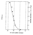
- the effective value of current increases with an increase in the capacitor capacitance.
- the data in this figure are those in the case where discharge is generated via a resistance estimated for a human body, 500 ⁇ , in the condition that the cable length is 25 m, the spark gap is 0.5 mm, and the discharge atmosphere is air.
- the effective value of current is about 14.8 mA
- the capacitor capacitance is 6 ⁇ 2.35 ⁇ 10 3 pF
- the effective value of current is about 15.8 mA, increasing by about 1 mA.
- the effective value of current can be kept low by selecting the period of application and stoppage of D.C. high voltage of the fixed period type high voltage controller 14.
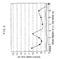
- the effective value of current fluctuates with the change in the applied frequency of D.C. high voltage.
- the data in this figure are those in the case where discharge is generated via a resistance estimated for a human body, 500 ⁇ , in the condition that the cable length is 25 m, the spark gap is 0.5 mm, and the discharge atmosphere is air, and also in the condition of a high voltage application duty of 50%.
- the increase/decrease in the effective value of current depends on the applied frequency of D.C. high voltage and the times of discharge, and when the applied frequency and the times of discharge agree with each other, the effective value of current is the lowest.
- the effective value of current-in the vicinity of the selected 1.5 Hz is about 8 mA, which meets the requirement of the IEC Standard and other standards.
- the apparatus is configured so that D.C. high voltage is not applied to the low-voltage portion of the welding power source and the like by using a diode 13.
- the capacitor 16 with a relatively high capacitance is connected, and the period of application and stoppage of D.C. high voltage is set by the fixed period type high voltage controller 14. Thereby, sufficient electric charges are supplied when spark discharge is generated, so that the current for transferring to arc discharge can be supplied, and also the effective value of the current can be kept low.
- the pulse signals are cut off by the disconnector 12, so that the output is stopped.
- the capacitor has a capacitance other than about 3 ⁇ 2.35 ⁇ 10 3 pF in the first embodiment, the same effect can be achieved by setting the frequency of pulse signals which keep the effective value of current low.
- the arc start ancillary apparatus is, as shown in FIG. 2, made up of a high voltage generator 15, a capacitor 16, and a controller, for example, a fixed period type high voltage controller 14.
- a controller for example, a fixed period type high voltage controller 14.
- the fixed period type high voltage controller 14 to which a welding start signal is input generates pulse signals with a fixed period to the high voltage generator 15.
- the high voltage generator 15 repeats the application and stoppage of D.C. high voltage according to the pulse signals.
- the capacitor 16 with a relatively high capacitance is connected, and the period of application and stoppage of D.C. high voltage is set by the fixed period type high voltage controller 14. Thereby, sufficient electric charges are supplied when spark discharge is generated, so that the current for transferring to arc discharge can be supplied, and also the effective value of the current can be kept low.
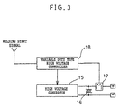
- the arc start ancillary apparatus in accordance with the present invention is, as shown in FIG. 3, made up of a variable duty type high voltage controller 18, a high voltage generator 15, a capacitor 16, and an effective current value detector 17.
- the high voltage generator 15 repeats the application and stoppage of D.C. high voltage according to the pulse signals from the variable duty type high voltage controller 18.
- the capacitor 16 is connected in parallel to the output of the high voltage generator 15. Specifically, the capacitor 16 is connected to a point between the plus side of the output of the high voltage generator 15 and the effective current value detector 17 and the minus side of the output of the high voltage generator 15.
- the current value is maintained by storing electric charges by using the capacitor 16 in the application of D.C. high voltage and by supplying the electric charges in transferring from spark discharge to arc discharge.
- the effective current value detector 17 which is connected in series to the plus side of the output of the high voltage generator 15, detects the effective value of current of spark discharge when D.C. high voltage is applied, and outputs it to the variable duty type high voltage controller 18.
- variable duty type high voltage controller 18 to which a welding start signal is input starts the output of pulse signals.
- the pulse duty is decreased, and the pulses are output so that the effective value of current does not exceed the specified value.
- the capacitor 16 with a relatively high capacitance is connected, and when the effective value of current exceeds the specified value at the effective current value detector 17, the pulse duty is decreased by the variable duty type high voltage controller 18, and the pulses are output so that the effective value of current does not exceed the specified value. Therefore, sufficient electric charges are supplied when spark discharge is generated, so that the current for transferring to arc discharge can be supplied, and also the effective value of the current can be kept low.
Landscapes
- Engineering & Computer Science (AREA)
- Physics & Mathematics (AREA)
- Plasma & Fusion (AREA)
- Mechanical Engineering (AREA)
- Arc Welding Control (AREA)
- Generation Of Surge Voltage And Current (AREA)
Description
- The present invention relates to an arc start ancillary apparatus according to the preamble of
claim 1. - Such an arc start ancillary apparatus for an arc welding machine has been disclosed in Japanese Patent Application Laid-Open No. 8-215843.
- As shown.in FIG. 6, a conventional arc welding machine is made up of an arc start
ancillary apparatus 19, awelding power source 10, awire 6, awire feeding motor 7, abase metal 8, and anelectrode 9. - This arc welding machine is configured so that welding current is supplied to between the
electrode 9 and thebase metal 8 by means of the low-voltagewelding power source 10 on receipt of a welding start signal, and thereby thewire feeding motor 7 is driven to feed thewire 6 to a weld location, by which arc welding is performed. - At the time of arc start, spark discharge is generated between the
base metal 8 and theelectrode 9 by applying a pulse-form D.C. high voltage, so that an insulating substance (for example, slug) at the tip end of the wire is destroyed by an electric shock of the generated spark discharge, or arc is induced by the creeping discharge on the insulating substance on thebase metal 8. - Thereby, the arc start performance is improved, and the safety is secured by restricting the effective value of current caused to flow at the time of discharge by the application of the pulse-form D.C. high voltage.
- The conventional arc start
ancillary apparatus 19 is made up of a D.C. high-voltage power source 1 for generating spark discharge, acapacitive load 2 for checking whether discharge is generated between theelectrode 9 and thebase metal 8, atimer circuit 3 for turning on/off the D.C. high-voltage power source 1 with a fixed period, aswitch 4, and adrooping resistor 5. - The following operation is repeated: A D.C. high voltage is applied by the D.C. high-
voltage power source 1 according to the input of a welding start signal, the current of spark discharge at the time when spark discharge is generated is detected by thecapacitive load 2, theswitch 4 of the D.C. high-voltage power source 1 is turned off according to thetimer circuit 3, and theswitch 4 of the D.C. high-voltage power source 1 is turned on again after an elapse of certain time. - To make the D.C. high voltage of the D.C. high-
voltage power source 1 pulse-form is an effective means for decreasing the effective value of current caused to flow by discharging. - However, there arises a problem in that the current in transferring from spark discharge to arc discharge cannot sometimes be secured, so that arc is not started.
- Also, although the aforesaid current can sometimes be secured by the floating capacitance by a cable or the like, the aforesaid current cannot be secured depending on the laying condition of cable.
- Also, although the
capacitive load 2 is provided in the conventional arc startancillary apparatus 19, thiscapacitive load 2 serves to detect discharge, but is not intended to improve the arc start performance. - An object of the present invention is to provide an arc start ancillary apparatus which improves the arc start performance for transferring from spark discharge to arc discharge, and keeps the effective value of current low by applying a pulse-form D.C. high voltage.
- This object is achieved by the features of
claim 1. - The arc start ancillary apparatus in accordance with the present invention is configured so that a capacitor with a relatively high capacitance is connected to secure a current for transferring from spark discharge to arc discharge, and a pulse-form D.C. high voltage is applied to keep the effective value of the current low.
- According to the present invention, the problem in that arc is not started is solved, and the effective value of current can be kept low by the improvement in arc start performance and the application of D.C. high voltage.
- The apparatus of the invention can improve the arc start performance by adding the discharge current of the capacitor to the output current of the high voltage generator.
- Also, when the effective value of current of D.C. high voltage exceeds the specified value at the effective current value detector, the effective value of current can be decreased by feeding back the change in pulse duty to the variable duty type high voltage controller so that the effective value of current does not exceed the specified value.
- More specifically, the apparatus is characterized in that when the capacitance of the capacitor is about 3 × 2.35 × 103 pF, the frequency of pulse signals is 1.5 Hz or near that value.
- As described above, according to the arc start ancillary apparatus in accordance with the present invention, the capacitor with a relatively high capacitance is connected, and the period of application and stoppage of D.C. high voltage is set by the controller. Thereby, sufficient electric charges are supplied when spark discharge is generated, so that the current for transferring to arc discharge can be supplied, and also the effective value of the current can be kept low and decreased to a safe value.
- Therefore, the problem in that arc is not started can be solved, and the arc start performance can be improved.
- Also, specifically, the period of application and stoppage of D.C. high voltage is made about 1.5 Hz by connecting the capacitor with a capacitance of 3 × 2.35 × 103 pF, by which sufficient electric charges are supplied when spark discharge is generated, so that the current for transferring to arc discharge can be supplied, the arc start performance can be improved, and the effective value of current can be kept low.
-
- FIG. 1 is a schematic view of an illustrative consumable electrode type arc welding machine;
- FIG. 2 is a schematic view of an illustrative arc start ancillary apparatus;
- FIG. 3 is a schematic view of an arc start ancillary apparatus in accordance with the present invention;
- FIG. 4 is a characteristic diagram showing the relationship between capacitor capacitance and effective current value;
- FIG. 5 is a characteristic diagram showing the relationship between applied frequency and effective current value and
- FIG. 6 is a schematic view of a conventional arc welding machine.
-
- The arc start ancillary apparatus in accordance with the present invention will now be described with reference to illustrative examples and to a specific embodiment.
- An example in which the arc start ancillary apparatus is applied to a consumable electrode type arc welding machine is explained below. This illustrative example is not covered by the claims, because the controller described is not a variable duty type high voltage controller.
- As shown in FIG. 1, a consumable electrode type arc welding machine is so configured that welding current is supplied to between an
electrode 9 and abase metal 8 by means of a low-voltagewelding power source 10 on receipt of a welding start signal, and thereby awire feeding motor 7 is driven to feed awire 6 to a weld location, by which arc welding is performed. - An arc start ancillary apparatus of the first embodiment of the present invention is, as shown in FIG. 1, made up of an
arc detector 11, adisconnector 12, ahigh voltage generator 15, acapacitor 16, and a controller, for example, a fixed period typehigh voltage controller 14. - In transferring from spark discharge to arc discharge at the time of arc start, the fixed period type
high voltage controller 14 on receipt of a welding start signal generates pulse signals with a fixed period to thehigh voltage generator 15 via thedisconnector 12. - The
high voltage generator 15 executes the generation and stoppage of D.C. high voltage with the period of the aforesaid pulse signals, so that a high voltage is supplied to between theelectrode 9 and thebase metal 8. - By the
capacitor 16 connected in parallel to the output of thehigh voltage generator 15, the current caused by the discharge of thecapacitor 16 is added to the output current of thehigh voltage generator 15, by which the transfer from spark discharge to arc discharge is facilitated to improve the arc start performance. - The addition of the current caused by the discharge of the
capacitor 16 increases the effective value of current. For the change of the effective value of current with respect to the change in capacitor capacitance at the time of continuous application of D.C. high voltage, as can be seen in FIG. 4, the effective value of current increases with an increase in the capacitor capacitance. The data in this figure are those in the case where discharge is generated via a resistance estimated for a human body, 500Ω, in the condition that the cable length is 25 m, the spark gap is 0.5 mm, and the discharge atmosphere is air. - For example, when the capacitor capacitance is 1 × 2.35 x 103 pF, the effective value of current is about 14.8 mA, and when the capacitor capacitance is 6 × 2.35 × 103 pF, the effective value of current is about 15.8 mA, increasing by about 1 mA.
- However, the effective value of current can be kept low by selecting the period of application and stoppage of D.C. high voltage of the fixed period type
high voltage controller 14. - For example, for the relationship between the applied frequency of D.C. high voltage and the effective value of current in the case where a capacitor capacitance of 3 x 2.35 × 103 pF is connected, as can be seen in FIG. 5, the effective value of current fluctuates with the change in the applied frequency of D.C. high voltage. The data in this figure, too, are those in the case where discharge is generated via a resistance estimated for a human body, 500Ω, in the condition that the cable length is 25 m, the spark gap is 0.5 mm, and the discharge atmosphere is air, and also in the condition of a high voltage application duty of 50%.
- The increase/decrease in the effective value of current depends on the applied frequency of D.C. high voltage and the times of discharge, and when the applied frequency and the times of discharge agree with each other, the effective value of current is the lowest.
- However, if the applied frequency of D.C. high voltage is too high, the voltage of spark discharge cannot be reached, so that an applied frequency of D.C. high voltage in the vicinity of 1.5 Hz is selected.
- The effective value of current-in the vicinity of the selected 1.5 Hz is about 8 mA, which meets the requirement of the IEC Standard and other standards.
- It is to be noted that when the welding current is detected by the
arc detector 11, the pulse signals are cut off by thedisconnector 12, so that the output is stopped. - Also, the apparatus is configured so that D.C. high voltage is not applied to the low-voltage portion of the welding power source and the like by using a
diode 13. - Thus, the
capacitor 16 with a relatively high capacitance is connected, and the period of application and stoppage of D.C. high voltage is set by the fixed period typehigh voltage controller 14. Thereby, sufficient electric charges are supplied when spark discharge is generated, so that the current for transferring to arc discharge can be supplied, and also the effective value of the current can be kept low. - When a welding current is detected by the
arc detector 11, the pulse signals are cut off by thedisconnector 12, so that the output is stopped. - Also, even when the capacitor has a capacitance other than about 3 × 2.35 × 103 pF in the first embodiment, the same effect can be achieved by setting the frequency of pulse signals which keep the effective value of current low.
- Also, although the case where the arc start ancillary apparatus is applied to the consumable electrode type arc welding machine has been explained in the first embodiment, the same effect can be achieved when the apparatus is applied to a non-consumable electrode type arc welding machine or some other welding machines.
- The arc start ancillary apparatus is, as shown in FIG. 2, made up of a
high voltage generator 15, acapacitor 16, and a controller, for example, a fixed period typehigh voltage controller 14. This illustrative example is not covered by the claims, because the controller described is not a variable duty type high voltage controller. - The fixed period type
high voltage controller 14 to which a welding start signal is input generates pulse signals with a fixed period to thehigh voltage generator 15. - The
high voltage generator 15 repeats the application and stoppage of D.C. high voltage according to the pulse signals. - By the
capacitor 16 connected in parallel to the output of thehigh voltage generator 15, the current caused by the discharge of thecapacitor 16 is added to the output current of thehigh voltage generator 15. - Thus, the
capacitor 16 with a relatively high capacitance is connected, and the period of application and stoppage of D.C. high voltage is set by the fixed period typehigh voltage controller 14. Thereby, sufficient electric charges are supplied when spark discharge is generated, so that the current for transferring to arc discharge can be supplied, and also the effective value of the current can be kept low. - The arc start ancillary apparatus in accordance with the present invention is, as shown in FIG. 3, made up of a variable duty type
high voltage controller 18, ahigh voltage generator 15, acapacitor 16, and an effectivecurrent value detector 17. - The
high voltage generator 15 repeats the application and stoppage of D.C. high voltage according to the pulse signals from the variable duty typehigh voltage controller 18. - The
capacitor 16 is connected in parallel to the output of thehigh voltage generator 15. Specifically, thecapacitor 16 is connected to a point between the plus side of the output of thehigh voltage generator 15 and the effectivecurrent value detector 17 and the minus side of the output of thehigh voltage generator 15. - The current value is maintained by storing electric charges by using the
capacitor 16 in the application of D.C. high voltage and by supplying the electric charges in transferring from spark discharge to arc discharge. - The effective
current value detector 17, which is connected in series to the plus side of the output of thehigh voltage generator 15, detects the effective value of current of spark discharge when D.C. high voltage is applied, and outputs it to the variable duty typehigh voltage controller 18. - The variable duty type
high voltage controller 18 to which a welding start signal is input starts the output of pulse signals. When the effective value of current exceeds the specified value at the effectivecurrent value detector 17, the pulse duty is decreased, and the pulses are output so that the effective value of current does not exceed the specified value. - Thus, the
capacitor 16 with a relatively high capacitance is connected, and when the effective value of current exceeds the specified value at the effectivecurrent value detector 17, the pulse duty is decreased by the variable duty typehigh voltage controller 18, and the pulses are output so that the effective value of current does not exceed the specified value. Therefore, sufficient electric charges are supplied when spark discharge is generated, so that the current for transferring to arc discharge can be supplied, and also the effective value of the current can be kept low.
Claims (3)
- An arc start ancillary apparatus, which is connected in parallel to a welding power source (10) for supplying electric power necessary for arc discharge between an electrode (9) and a base metal (8), for supplying a pulse-form electric current in transferring from spark discharge to arc discharge, which comprises:characterized in thata high voltage generator (15) for executing the generation and stoppage of a D.C. high voltage with the period of pulse signals;a capacitor (16) connected in parallel to the output of said high voltage generator (15);a controller (18) for generating said pulse signals;wherein the effective current value outputted from the detector (17) is fed back to the variable duty type high voltage controller (18) which is arranged to change and set the pulse duty so that the effective value of the current between said electrode (9) and said base metal (8) is kept below a specified value.an effective current value detector (17), which is connected in series to the plus side of the output of said high voltage generator (15), for detecting and outputting the effective value of a current supplied to said electrode in transferring from spark discharge to arch discharge; anda variable duty type high voltage controller (18) for changing the duty of said pulse and outputting pulse signals according to a welding start signal,
- The arc start ancillary apparatus according to claim 1, wherein when the capacitance of the capacitor is about 3 x 2.35 x 103 pF, the frequency of pulse signals is 1.5 Hz or near that value.
- The arc start ancillary apparatus according to claim 1, comprising a disconnector (12) for cutting off and stopping pulse signals according to the welding current value of the effective current value detector (17).
Applications Claiming Priority (3)
| Application Number | Priority Date | Filing Date | Title |
|---|---|---|---|
| JP211073/97 | 1997-08-06 | ||
| JP09211073A JP3078245B2 (en) | 1997-08-06 | 1997-08-06 | Arc start assist device |
| JP21107397 | 1997-08-06 |
Publications (2)
| Publication Number | Publication Date |
|---|---|
| EP0900620A1 EP0900620A1 (en) | 1999-03-10 |
| EP0900620B1 true EP0900620B1 (en) | 2002-11-13 |
Family
ID=16599967
Family Applications (1)
| Application Number | Title | Priority Date | Filing Date |
|---|---|---|---|
| EP98114821A Expired - Lifetime EP0900620B1 (en) | 1997-08-06 | 1998-08-06 | Arc start ancillary apparatus |
Country Status (6)
| Country | Link |
|---|---|
| US (1) | US6066831A (en) |
| EP (1) | EP0900620B1 (en) |
| JP (1) | JP3078245B2 (en) |
| KR (1) | KR100288645B1 (en) |
| CN (1) | CN1061919C (en) |
| DE (1) | DE69809354T2 (en) |
Families Citing this family (9)
| Publication number | Priority date | Publication date | Assignee | Title |
|---|---|---|---|---|
| DE10122104C1 (en) * | 2001-05-07 | 2002-08-29 | Ewm Hightec Welding Gmbh | Arc welding device with HF blocking choke and additional secondary winding |
| AT413953B (en) * | 2003-11-25 | 2006-07-15 | Fronius Int Gmbh | METHOD AND CIRCUIT FOR TOUCH-FREE IGNITION OF A WELDING ARC |
| US7339135B2 (en) * | 2004-06-04 | 2008-03-04 | Illinois Tool Works Inc. | Welding arc stabilization process |
| US9000329B2 (en) * | 2004-07-22 | 2015-04-07 | Illinois Tool Works Inc. | Welding arc stabilization process |
| US9808881B2 (en) * | 2015-03-03 | 2017-11-07 | Illinois Tool Works Inc. | Method and apparatus for providing welding and auxiliary power |
| CN104959704B (en) * | 2015-07-15 | 2017-03-08 | 胡达广 | Numerical control electric welding machine |
| CN105081525B (en) * | 2015-09-14 | 2016-09-07 | 山东大学 | A kind of electric arc processes discharging headlamp system |
| JP7004257B2 (en) * | 2017-11-09 | 2022-01-21 | 株式会社ダイヘン | Welding power supply |
| CN115372772A (en) * | 2022-09-13 | 2022-11-22 | 国网湖南省电力有限公司 | Arc fault real-time detection semi-physical simulation experiment platform suitable for multiple scenes |
Family Cites Families (7)
| Publication number | Priority date | Publication date | Assignee | Title |
|---|---|---|---|---|
| GB8400685D0 (en) * | 1984-01-11 | 1984-02-15 | Welding Inst | Shielded arc welding |
| US4672175A (en) * | 1985-06-10 | 1987-06-09 | Hy-Tek Systems, Inc. | Arc starter for welder |
| US5264679A (en) * | 1992-05-04 | 1993-11-23 | Martin Donald L | Alternating current welding apparatus |
| EP0585068B1 (en) * | 1992-08-25 | 1998-04-15 | Matsushita Electric Industrial Co., Ltd. | Arc welding machine and plasma cutting machine |
| CN1096975A (en) * | 1993-07-02 | 1995-01-04 | 陈大可 | A kind of electric welding or TURP cut the high voltage arc generating device in the equipment |
| JP3287164B2 (en) * | 1995-02-20 | 2002-05-27 | 松下電器産業株式会社 | DC high voltage generator |
| US5852278A (en) * | 1995-12-28 | 1998-12-22 | Matsushita Electric Industrial Co., Ltd. | Arc welding and arc plasma cutting machines having improved DC high-voltage generator |
-
1997
- 1997-08-06 JP JP09211073A patent/JP3078245B2/en not_active Expired - Fee Related
-
1998
- 1998-08-04 KR KR1019980031679A patent/KR100288645B1/en not_active Expired - Fee Related
- 1998-08-04 US US09/128,418 patent/US6066831A/en not_active Expired - Lifetime
- 1998-08-06 CN CN98116262A patent/CN1061919C/en not_active Expired - Fee Related
- 1998-08-06 EP EP98114821A patent/EP0900620B1/en not_active Expired - Lifetime
- 1998-08-06 DE DE69809354T patent/DE69809354T2/en not_active Expired - Lifetime
Also Published As
| Publication number | Publication date |
|---|---|
| KR19990023334A (en) | 1999-03-25 |
| JPH1147928A (en) | 1999-02-23 |
| JP3078245B2 (en) | 2000-08-21 |
| US6066831A (en) | 2000-05-23 |
| CN1061919C (en) | 2001-02-14 |
| DE69809354T2 (en) | 2003-03-20 |
| EP0900620A1 (en) | 1999-03-10 |
| CN1208679A (en) | 1999-02-24 |
| DE69809354D1 (en) | 2002-12-19 |
| KR100288645B1 (en) | 2001-05-02 |
Similar Documents
| Publication | Publication Date | Title |
|---|---|---|
| EP0607819B1 (en) | Pulsed arc welding apparatus having a consumable electrode wire | |
| US9333581B2 (en) | Apparatus and method for energy replacement in a welding waveform during welding | |
| US6066831A (en) | ARC start ancillary apparatus | |
| US5530220A (en) | Plasma torch arc transfer circuit | |
| US7012435B2 (en) | State detecting method and insulation resistance fall detector | |
| JP2016501725A (en) | Arc welding system having an engine generator and a battery, and a method for controlling battery charging in such an arc welding system | |
| EP1578553B1 (en) | Solid state switch for arc welding | |
| CA2259789C (en) | Method and apparatus for stopping a welding process | |
| EP0965409A3 (en) | Method of controlling pulse output and consumable electrode type pulse arc welding device | |
| JP2682276B2 (en) | Power supply for electric discharge machine | |
| US20020053560A1 (en) | Engine driven welder with field current boost | |
| WO2020235293A1 (en) | Arc welding method and arc welding device | |
| EP3388180B1 (en) | Welding system and method with short circuit welding using self-shielded electrode | |
| WO1987007860A1 (en) | Discharge machining controller | |
| SE9701696D0 (en) | Method and device for arc welding with melting electrode | |
| JP2768277B2 (en) | Arc welding machine and plasma cutting machine | |
| JPS5756158A (en) | Consumable electrode type welding machine | |
| JP3696923B2 (en) | Arc processing equipment | |
| JP3463965B2 (en) | Plasma arc processing equipment | |
| JP3076946B2 (en) | Arc welding machine and plasma cutting machine | |
| KR0178584B1 (en) | Power unit of wire electric discharge machine | |
| JPH07251096A (en) | Power source controller for electric dust collector | |
| JPH0910948A (en) | Plasma arc machining equipment | |
| KR910007049Y1 (en) | Protecting circuit for smps | |
| JPH0320045Y2 (en) |
Legal Events
| Date | Code | Title | Description |
|---|---|---|---|
| PUAI | Public reference made under article 153(3) epc to a published international application that has entered the european phase |
Free format text: ORIGINAL CODE: 0009012 |
|
| AK | Designated contracting states |
Kind code of ref document: A1 Designated state(s): DE FR GB |
|
| AX | Request for extension of the european patent |
Free format text: AL;LT;LV;MK;RO;SI |
|
| 17P | Request for examination filed |
Effective date: 19990122 |
|
| AKX | Designation fees paid |
Free format text: DE FR GB |
|
| 17Q | First examination report despatched |
Effective date: 20000602 |
|
| GRAG | Despatch of communication of intention to grant |
Free format text: ORIGINAL CODE: EPIDOS AGRA |
|
| GRAG | Despatch of communication of intention to grant |
Free format text: ORIGINAL CODE: EPIDOS AGRA |
|
| GRAH | Despatch of communication of intention to grant a patent |
Free format text: ORIGINAL CODE: EPIDOS IGRA |
|
| GRAH | Despatch of communication of intention to grant a patent |
Free format text: ORIGINAL CODE: EPIDOS IGRA |
|
| GRAA | (expected) grant |
Free format text: ORIGINAL CODE: 0009210 |
|
| AK | Designated contracting states |
Kind code of ref document: B1 Designated state(s): DE FR GB |
|
| REG | Reference to a national code |
Ref country code: GB Ref legal event code: FG4D |
|
| REF | Corresponds to: |
Ref document number: 69809354 Country of ref document: DE Date of ref document: 20021219 |
|
| ET | Fr: translation filed | ||
| PLBE | No opposition filed within time limit |
Free format text: ORIGINAL CODE: 0009261 |
|
| STAA | Information on the status of an ep patent application or granted ep patent |
Free format text: STATUS: NO OPPOSITION FILED WITHIN TIME LIMIT |
|
| 26N | No opposition filed |
Effective date: 20030814 |
|
| REG | Reference to a national code |
Ref country code: GB Ref legal event code: 746 Effective date: 20091215 |
|
| REG | Reference to a national code |
Ref country code: FR Ref legal event code: PLFP Year of fee payment: 19 |
|
| PGFP | Annual fee paid to national office [announced via postgrant information from national office to epo] |
Ref country code: DE Payment date: 20160802 Year of fee payment: 19 Ref country code: GB Payment date: 20160803 Year of fee payment: 19 |
|
| PGFP | Annual fee paid to national office [announced via postgrant information from national office to epo] |
Ref country code: FR Payment date: 20160712 Year of fee payment: 19 |
|
| REG | Reference to a national code |
Ref country code: DE Ref legal event code: R119 Ref document number: 69809354 Country of ref document: DE |
|
| GBPC | Gb: european patent ceased through non-payment of renewal fee |
Effective date: 20170806 |
|
| REG | Reference to a national code |
Ref country code: FR Ref legal event code: ST Effective date: 20180430 |
|
| PG25 | Lapsed in a contracting state [announced via postgrant information from national office to epo] |
Ref country code: GB Free format text: LAPSE BECAUSE OF NON-PAYMENT OF DUE FEES Effective date: 20170806 Ref country code: DE Free format text: LAPSE BECAUSE OF NON-PAYMENT OF DUE FEES Effective date: 20180301 |
|
| PG25 | Lapsed in a contracting state [announced via postgrant information from national office to epo] |
Ref country code: FR Free format text: LAPSE BECAUSE OF NON-PAYMENT OF DUE FEES Effective date: 20170831 |