EP0899800A2 - Assembling set of elements for assembling scaffoldings - Google Patents
Assembling set of elements for assembling scaffoldings Download PDFInfo
- Publication number
- EP0899800A2 EP0899800A2 EP98110880A EP98110880A EP0899800A2 EP 0899800 A2 EP0899800 A2 EP 0899800A2 EP 98110880 A EP98110880 A EP 98110880A EP 98110880 A EP98110880 A EP 98110880A EP 0899800 A2 EP0899800 A2 EP 0899800A2
- Authority
- EP
- European Patent Office
- Prior art keywords
- elements
- cross
- members
- uprights
- screw
- Prior art date
- Legal status (The legal status is an assumption and is not a legal conclusion. Google has not performed a legal analysis and makes no representation as to the accuracy of the status listed.)
- Ceased
Links
Images



Classifications
-
- F—MECHANICAL ENGINEERING; LIGHTING; HEATING; WEAPONS; BLASTING
- F16—ENGINEERING ELEMENTS AND UNITS; GENERAL MEASURES FOR PRODUCING AND MAINTAINING EFFECTIVE FUNCTIONING OF MACHINES OR INSTALLATIONS; THERMAL INSULATION IN GENERAL
- F16B—DEVICES FOR FASTENING OR SECURING CONSTRUCTIONAL ELEMENTS OR MACHINE PARTS TOGETHER, e.g. NAILS, BOLTS, CIRCLIPS, CLAMPS, CLIPS OR WEDGES; JOINTS OR JOINTING
- F16B12/00—Jointing of furniture or the like, e.g. hidden from exterior
- F16B12/10—Jointing of furniture or the like, e.g. hidden from exterior using pegs, bolts, tenons, clamps, clips, or the like
- F16B12/28—Jointing of furniture or the like, e.g. hidden from exterior using pegs, bolts, tenons, clamps, clips, or the like for metal furniture parts
- F16B12/32—Jointing of furniture or the like, e.g. hidden from exterior using pegs, bolts, tenons, clamps, clips, or the like for metal furniture parts using clamps, clips, wedges, sliding bolts, or the like
-
- H—ELECTRICITY
- H01—ELECTRIC ELEMENTS
- H01M—PROCESSES OR MEANS, e.g. BATTERIES, FOR THE DIRECT CONVERSION OF CHEMICAL ENERGY INTO ELECTRICAL ENERGY
- H01M50/00—Constructional details or processes of manufacture of the non-active parts of electrochemical cells other than fuel cells, e.g. hybrid cells
- H01M50/20—Mountings; Secondary casings or frames; Racks, modules or packs; Suspension devices; Shock absorbers; Transport or carrying devices; Holders
- H01M50/262—Mountings; Secondary casings or frames; Racks, modules or packs; Suspension devices; Shock absorbers; Transport or carrying devices; Holders with fastening means, e.g. locks
-
- A—HUMAN NECESSITIES
- A47—FURNITURE; DOMESTIC ARTICLES OR APPLIANCES; COFFEE MILLS; SPICE MILLS; SUCTION CLEANERS IN GENERAL
- A47B—TABLES; DESKS; OFFICE FURNITURE; CABINETS; DRAWERS; GENERAL DETAILS OF FURNITURE
- A47B47/00—Cabinets, racks or shelf units, characterised by features related to dismountability or building-up from elements
- A47B47/02—Cabinets, racks or shelf units, characterised by features related to dismountability or building-up from elements made of metal only
- A47B47/021—Racks or shelf units
- A47B47/027—Racks or shelf units with frames only
-
- Y—GENERAL TAGGING OF NEW TECHNOLOGICAL DEVELOPMENTS; GENERAL TAGGING OF CROSS-SECTIONAL TECHNOLOGIES SPANNING OVER SEVERAL SECTIONS OF THE IPC; TECHNICAL SUBJECTS COVERED BY FORMER USPC CROSS-REFERENCE ART COLLECTIONS [XRACs] AND DIGESTS
- Y02—TECHNOLOGIES OR APPLICATIONS FOR MITIGATION OR ADAPTATION AGAINST CLIMATE CHANGE
- Y02E—REDUCTION OF GREENHOUSE GAS [GHG] EMISSIONS, RELATED TO ENERGY GENERATION, TRANSMISSION OR DISTRIBUTION
- Y02E60/00—Enabling technologies; Technologies with a potential or indirect contribution to GHG emissions mitigation
- Y02E60/10—Energy storage using batteries
Definitions
- the present invention relates to an assembling set of elements for assembling scaffoldings. More specifically, the assembling set of elements according to the invention may be used for assembling scaffoldings for housing electric batteries therein.
- prior scaffoldings for the above mentioned application usually comprise a plurality of supporting elements connected to one another by cross-members supporting one or more rows of uprights.
- cross-members supporting one or more rows of uprights.
- diagonal elements coupled to the uprights are moreover used.
- the connection between the uprights and cross-members is carried out by a section member having a recessed portion thereof the shape of which depends on the cross-member cross-section shape, as well as two perforated wings.
- the section member can be used for coupling two elements forming the mentioned upright to a cross-members thereagainst the section member abuts by its central portion.
- the invention sets out to make the above mentioned scaffoldings with a simpler construction and a more rational use of the elements constituting said scaffoldings.
- a main object of the present invention is to provide an assembly set of elements for assembling scaffoldings for electric batteries including a small number of structural elements.
- Another object of the present invention is to provide such an assembling set of elements allowing to easily disassemble the structural component elements thereof, thereby facilitating the transport of the scaffolding constructional elements.
- an assembling set of elements for assembling scaffoldings for housing electric batteries therein said scaffolding being of a type comprising a plurality of uprights supported by supporting elements including cross-members, a plurality of connecting elements for connecting the uprights and cross-members and a plurality of foot elements for said supporting elements, characterized in that said elements for coupling said uprights and cross-members comprise at least a pair of symmetrical section members, each of which is provided for engagement in a recess formed in said uprights and each being provided with a perforated portion therethrough fixing means are engaged, and that each said cross-member is provided, in the inside thereof, with threaded elements coaxial with said cross-member and adapted to receive a connecting screw for connecting said cross-member to corresponding supporting elements therefor.
- each symmetrical section member comprises a first and second portion, arranged with a L arrangement with respect to one another, each of which extends from each said perforated portion, said first portion being provided for engagement in one of the recesses formed in said uprights, thereby the section members, as they are brought to a mutual adjoining relationship, define a seat for housing therein said cross-members.
- each said upright comprises a further recess or slot for receiving therein one of said section members to allow the coupled section members to connect two adjoining uprights.
- the supporting feet comprise a screw embedded in a supporting element contacting the ground and a ring-nut engaging said screw to adjust the height of the supporting element associated with the foot element.
- each of the connecting elements coupling the uprights and cross-members requires a single connecting screw and the related nut, thereby allowing to reduce the material and time required for assembling the scaffolding.
- the assembling system of the invention is suitable for connecting both a cross-member to an end upright, and a central or middle cross-member to two adjoining uprights.
- the provision of cross-members provided with inner threaded elements allows to easily construct a very simple system for assembling and disassembling the cross-member/supporting element sets, while facilitating the shipment of the scaffoldings to the assembling place.
- FIG. 1 is an axonometric view illustrating a scaffolding of a type which is generally used for housing electric batteries therein.
- the scaffolding generally indicated by the reference number 1, comprises a plurality of supporting elements 4, in turn supported by adjustable foot elements 5, which are connected by pairs to the cross-members 3.
- the cross-members 3 support the uprights 2 thereon the electric batteries (not shown) are arranged.
- the scaffolding 1 is stiffened by diagonal elements 6, coupled to the supporting elements 4 by the connecting elements 25.
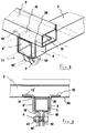
- FIG. 2 shows a connecting element, generally indicated by the reference number 11, which is engaged to connect a cross-member 3 and an upright 2.
- Said connecting element 11 comprises a pair of metal section-members which are symmetrically arranged to house the cross-member 3.
- each said section member comprises perforated portions 10 and 10', and L-shape portions including a first portion 8, 8' and a second portion 12, 12'.
- Said L-shape portions are coupled to said perforated portions 10, 10' by coupling segments 18 and 18'.
- each said portion 12, 12' is threaded into corresponding slots 30 and 31, formed on the bottom surface 50 of the upright 2.
- Said section members are so arranged that the portions 12 and 12' face outwardly so as to cause the portions 8 and 8' to move toward one another, thereby said segments 18 and 18' will provide, in combination, a housing for the cross-member 3.
- said two section members will be connected and fixed in their connected position by engaging the screw 9 in the holes of the perforated portions 10 and 10' and by clamping the screw by the clamping or locking nut 47.
- Figure 4 is an exploded view clearly illustrating the components of the connecting elements for connecting the cross-members 3 and uprights 2.
- the cross-member portion 2 is provided, according to a preferred embodiment of the invention, in addition to the above mentioned slots 30 and 31, with a third additional slot 32.
- this slot 32 will allow an upright 2 to be easily connected to a like adjoining upright (not shown) in the central part of the scaffolding 1.
- Figure 5 illustrates a cross-sectional view, substantially taken through a plane parallel to the axis of the upright 4 of a threaded element 16, which is coaxially connected to the cross-member 3.
- the threaded element 16 in particular, receives therein the screw 27 to connect the cross-member 3 to the corresponding supporting element 4.
- FIG. 6 is a partial cross-sectional view illustrating a supporting foot element for supporting the scaffolding 1. More specifically, the foot element 5 comprises a screw 29 embedded in a supporting element 22 contacting the ground and a ring-nut 21 engaging with the screw 29 so as to make an adjustment of the supporting element 4 engaged with the foot element 5 possible.
- FIG. 7 is an axonometric view illustrating a detail of the connection between the diagonal elements 6 and vertical supporting elements 4, according to the present invention.
- This connection is preferably made by two symmetrical section members 26 which can be brought to a mutual adjoining relationship.
- Said section members 26, in particular, are so designed that, in an adjoining position, they will encompass the substantially rectangular cross-section profile or contour of the supporting element 4.
- the section members 26 are brought to their mutual adjoining relationship so as to connect the end portions of the diagonal elements 6, and being then fixed in their operating position by a screw 41 engaged in the supporting element 4 and by screw 42 connecting the end portions of the diagonal elements 6 inside said adjoined section members.
- a metal element for example of an iron material, of U cross-section, to be inserted into each of said uprights 2, to increase the structural stiffness thereof and prevent said uprights from being deformed by the weights of the supported batteries.
Landscapes
- Chemical & Material Sciences (AREA)
- Chemical Kinetics & Catalysis (AREA)
- Electrochemistry (AREA)
- General Chemical & Material Sciences (AREA)
- Engineering & Computer Science (AREA)
- General Engineering & Computer Science (AREA)
- Mechanical Engineering (AREA)
- Mutual Connection Of Rods And Tubes (AREA)
- Battery Mounting, Suspending (AREA)
- Sampling And Sample Adjustment (AREA)
Abstract
Description
Claims (5)
- An assembling set of elements for assembling scaffoldings for housing electric batteries therein, said scaffolding being of a type comprising a plurality of uprights supported by supporting elements including cross-members, a plurality of connecting elements for connecting the uprights and cross-members and a plurality of foot elements for said supporting elements, characterized in that said elements for coupling said uprights and cross-members comprise at least a pair of symmetrical section members, each of which is provided for engagement in a recess formed in said uprights and each being provided with a perforated portion therethrough fixing means are engaged, and that each said cross-member is provided, in the inside thereof, with threaded elements coaxial with said cross-member and adapted to receive a connecting screw for connecting said cross-member to corresponding supporting elements therefor.
- An assembling set of elements according to Claim 1, characterized in that each said symmetrical section-member comprises a first and a second portion, arranged with a L-shape arrangement, and extended from each of said perforated portions, said first portion being engageable in one of said slots formed in said uprights, thereby said section members, as they are brought to a mutual adjoined relationship, will define a seat for receiving therein said cross-members.
- An assembling set of elements according to Claim 1, characterized in that each said upright comprises a further slot for receiving therein one of said section members thereby allowing said section members to connect two adjoining uprights.
- An assembling set of elements according to Claim 1, characterized in that said fixing means engaging said perforated portions comprise a screw and a nut assembly.
- An assembling set of elements according to Claim 1, characterized in that said supporting foot elements comprise a screw embedded in a supporting element contacting the ground and a ring-nut engaging said screw so as to adjust the height of the supporting element associated with said foot element.
Applications Claiming Priority (2)
| Application Number | Priority Date | Filing Date | Title |
|---|---|---|---|
| ITMI970458U | 1997-06-24 | ||
| IT1997MI000458U IT237615Y1 (en) | 1997-06-24 | 1997-06-24 | COMPLEX OF COMPONENTS FOR THE ASSEMBLY OF SHELVING |
Publications (2)
| Publication Number | Publication Date |
|---|---|
| EP0899800A2 true EP0899800A2 (en) | 1999-03-03 |
| EP0899800A3 EP0899800A3 (en) | 1999-08-18 |
Family
ID=11376249
Family Applications (1)
| Application Number | Title | Priority Date | Filing Date |
|---|---|---|---|
| EP98110880A Ceased EP0899800A3 (en) | 1997-06-24 | 1998-06-15 | Assembling set of elements for assembling scaffoldings |
Country Status (3)
| Country | Link |
|---|---|
| EP (1) | EP0899800A3 (en) |
| CA (1) | CA2240796A1 (en) |
| IT (1) | IT237615Y1 (en) |
Cited By (2)
| Publication number | Priority date | Publication date | Assignee | Title |
|---|---|---|---|---|
| EP1169953A1 (en) * | 2000-07-06 | 2002-01-09 | Matthias Biehler | Rack for food and drinks |
| CN101593937A (en) * | 2008-04-01 | 2009-12-02 | 施耐德电器工业公司 | Cabinet components |
Family Cites Families (4)
| Publication number | Priority date | Publication date | Assignee | Title |
|---|---|---|---|---|
| IT1137350B (en) * | 1981-04-14 | 1986-09-10 | Fim Co Me Spa | METALLIC STRUCTURES FOR THE STORAGE OF PRODUCTS AND FOR SHELVING |
| DE8607513U1 (en) * | 1986-03-19 | 1986-04-30 | Kunstmann, Dieter J., 8938 Buchloe | Floor and tier frame for emergency batteries that can be plugged together from individual elements |
| FR2651842B3 (en) * | 1989-09-14 | 1991-11-29 | Contastin Andre | DEVICE FOR FIXING A LATTE ON A METAL ELEMENT, PARTICULARLY THE SIDE OF A BED FRAME AND THE BED FRAME THEREFORE. |
| US5680942A (en) * | 1995-05-18 | 1997-10-28 | Metal Masters Foodservice Equipment Co., Inc. | Overhead track high density storage system with center and side guide rollers and caster lock alignment clip |
-
1997
- 1997-06-24 IT IT1997MI000458U patent/IT237615Y1/en active IP Right Grant
-
1998
- 1998-06-15 EP EP98110880A patent/EP0899800A3/en not_active Ceased
- 1998-06-16 CA CA002240796A patent/CA2240796A1/en not_active Abandoned
Cited By (3)
| Publication number | Priority date | Publication date | Assignee | Title |
|---|---|---|---|---|
| EP1169953A1 (en) * | 2000-07-06 | 2002-01-09 | Matthias Biehler | Rack for food and drinks |
| CN101593937A (en) * | 2008-04-01 | 2009-12-02 | 施耐德电器工业公司 | Cabinet components |
| CN101593937B (en) * | 2008-04-01 | 2014-07-16 | 施耐德电器工业公司 | Assembly of an electrical cabinet |
Also Published As
| Publication number | Publication date |
|---|---|
| IT237615Y1 (en) | 2000-09-13 |
| ITMI970458V0 (en) | 1997-06-24 |
| EP0899800A3 (en) | 1999-08-18 |
| ITMI970458U1 (en) | 1998-12-24 |
| CA2240796A1 (en) | 1998-12-24 |
Similar Documents
| Publication | Publication Date | Title |
|---|---|---|
| RU2195748C2 (en) | Modular assembled rack with earthquake-proof holding facility in particular for storage batteries | |
| US4435927A (en) | Modular building structure and module for it | |
| KR101985204B1 (en) | Cable tray of apartment building | |
| US6021721A (en) | Pallet | |
| US5785447A (en) | Connector for structural apparatus | |
| US20020194801A1 (en) | Cable support apparatus for a raised floor system | |
| FI96631B (en) | Support system | |
| HU221572B (en) | A metal frame with a hyperstatic assembly wedge, notably for an electrical cabinet framework | |
| EP0899800A2 (en) | Assembling set of elements for assembling scaffoldings | |
| WO2001001533A1 (en) | Frame structure for an enclosure for electrical equipment | |
| US5964546A (en) | Split separable joint apparatus and method | |
| KR20160133080A (en) | Prefabricated table frame | |
| KR102042237B1 (en) | Cable tray | |
| KR200428188Y1 (en) | Scaffolding for building scaffolding | |
| KR20180096035A (en) | Hub Connector for Geodesic Dome | |
| GB2226060A (en) | Support foot for raised floors | |
| KR101656736B1 (en) | the connect tool for assembly furniture and the assembly furniture therewith | |
| EP0044282A2 (en) | Metallic shelving provided with multiple interlocking means, and components designed for producing this shelving | |
| US3479071A (en) | Connector unit | |
| KR100835681B1 (en) | Construction scaffolding | |
| SK75393A3 (en) | Connecting element for connecting construction units | |
| KR200424416Y1 (en) | Construction scaffolding | |
| CN213333496U (en) | Display support and display assembly | |
| KR100405658B1 (en) | Stand for flat display | |
| US5349502A (en) | Universal lattice for magnetic electronic article surveillance system |
Legal Events
| Date | Code | Title | Description |
|---|---|---|---|
| PUAI | Public reference made under article 153(3) epc to a published international application that has entered the european phase |
Free format text: ORIGINAL CODE: 0009012 |
|
| AK | Designated contracting states |
Kind code of ref document: A2 Designated state(s): AT DE DK ES FI FR GB IE IT NL SE |
|
| AX | Request for extension of the european patent |
Free format text: AL;LT;LV;MK;RO;SI |
|
| PUAL | Search report despatched |
Free format text: ORIGINAL CODE: 0009013 |
|
| AK | Designated contracting states |
Kind code of ref document: A3 Designated state(s): AT BE CH CY DE DK ES FI FR GB GR IE IT LI LU MC NL PT SE |
|
| AX | Request for extension of the european patent |
Free format text: AL;LT;LV;MK;RO;SI |
|
| 17P | Request for examination filed |
Effective date: 19991126 |
|
| AKX | Designation fees paid |
Free format text: AT DE DK ES FI FR GB IE IT NL SE |
|
| GRAG | Despatch of communication of intention to grant |
Free format text: ORIGINAL CODE: EPIDOS AGRA |
|
| 17Q | First examination report despatched |
Effective date: 20010607 |
|
| STAA | Information on the status of an ep patent application or granted ep patent |
Free format text: STATUS: THE APPLICATION HAS BEEN REFUSED |
|
| 18R | Application refused |
Effective date: 20011203 |