EP0899082A2 - Process and apparatus for severing open sections of tubular webs - Google Patents
Process and apparatus for severing open sections of tubular webs Download PDFInfo
- Publication number
- EP0899082A2 EP0899082A2 EP98115604A EP98115604A EP0899082A2 EP 0899082 A2 EP0899082 A2 EP 0899082A2 EP 98115604 A EP98115604 A EP 98115604A EP 98115604 A EP98115604 A EP 98115604A EP 0899082 A2 EP0899082 A2 EP 0899082A2
- Authority
- EP
- European Patent Office
- Prior art keywords
- film tube
- mandrel
- conveyor
- vessels
- film
- Prior art date
- Legal status (The legal status is an assumption and is not a legal conclusion. Google has not performed a legal analysis and makes no representation as to the accuracy of the status listed.)
- Granted
Links
Images


Classifications
-
- B—PERFORMING OPERATIONS; TRANSPORTING
- B65—CONVEYING; PACKING; STORING; HANDLING THIN OR FILAMENTARY MATERIAL
- B65B—MACHINES, APPARATUS OR DEVICES FOR, OR METHODS OF, PACKAGING ARTICLES OR MATERIALS; UNPACKING
- B65B9/00—Enclosing successive articles, or quantities of material, e.g. liquids or semiliquids, in flat, folded, or tubular webs of flexible sheet material; Subdividing filled flexible tubes to form packages
- B65B9/10—Enclosing successive articles, or quantities of material, in preformed tubular webs, or in webs formed into tubes around filling nozzles, e.g. extruded tubular webs
- B65B9/13—Enclosing successive articles, or quantities of material, in preformed tubular webs, or in webs formed into tubes around filling nozzles, e.g. extruded tubular webs the preformed tubular webs being supplied in a flattened state
- B65B9/14—Devices for distending tubes supplied in the flattened state
-
- B—PERFORMING OPERATIONS; TRANSPORTING
- B26—HAND CUTTING TOOLS; CUTTING; SEVERING
- B26D—CUTTING; DETAILS COMMON TO MACHINES FOR PERFORATING, PUNCHING, CUTTING-OUT, STAMPING-OUT OR SEVERING
- B26D3/00—Cutting work characterised by the nature of the cut made; Apparatus therefor
- B26D3/16—Cutting rods or tubes transversely
- B26D3/161—Cutting rods or tubes transversely for obtaining more than one product at a time
-
- B—PERFORMING OPERATIONS; TRANSPORTING
- B26—HAND CUTTING TOOLS; CUTTING; SEVERING
- B26D—CUTTING; DETAILS COMMON TO MACHINES FOR PERFORATING, PUNCHING, CUTTING-OUT, STAMPING-OUT OR SEVERING
- B26D3/00—Cutting work characterised by the nature of the cut made; Apparatus therefor
- B26D3/16—Cutting rods or tubes transversely
- B26D3/164—Cutting rods or tubes transversely characterised by means for supporting the tube from the inside
-
- B—PERFORMING OPERATIONS; TRANSPORTING
- B26—HAND CUTTING TOOLS; CUTTING; SEVERING
- B26D—CUTTING; DETAILS COMMON TO MACHINES FOR PERFORATING, PUNCHING, CUTTING-OUT, STAMPING-OUT OR SEVERING
- B26D3/00—Cutting work characterised by the nature of the cut made; Apparatus therefor
- B26D3/16—Cutting rods or tubes transversely
- B26D3/166—Trimming tube-ends
-
- B—PERFORMING OPERATIONS; TRANSPORTING
- B29—WORKING OF PLASTICS; WORKING OF SUBSTANCES IN A PLASTIC STATE IN GENERAL
- B29C—SHAPING OR JOINING OF PLASTICS; SHAPING OF MATERIAL IN A PLASTIC STATE, NOT OTHERWISE PROVIDED FOR; AFTER-TREATMENT OF THE SHAPED PRODUCTS, e.g. REPAIRING
- B29C63/00—Lining or sheathing, i.e. applying preformed layers or sheathings of plastics; Apparatus therefor
- B29C63/38—Lining or sheathing, i.e. applying preformed layers or sheathings of plastics; Apparatus therefor by liberation of internal stresses
- B29C63/42—Lining or sheathing, i.e. applying preformed layers or sheathings of plastics; Apparatus therefor by liberation of internal stresses using tubular layers or sheathings
- B29C63/423—Lining or sheathing, i.e. applying preformed layers or sheathings of plastics; Apparatus therefor by liberation of internal stresses using tubular layers or sheathings specially applied to the mass-production of externally coated articles, e.g. bottles
-
- B—PERFORMING OPERATIONS; TRANSPORTING
- B65—CONVEYING; PACKING; STORING; HANDLING THIN OR FILAMENTARY MATERIAL
- B65B—MACHINES, APPARATUS OR DEVICES FOR, OR METHODS OF, PACKAGING ARTICLES OR MATERIALS; UNPACKING
- B65B9/00—Enclosing successive articles, or quantities of material, e.g. liquids or semiliquids, in flat, folded, or tubular webs of flexible sheet material; Subdividing filled flexible tubes to form packages
- B65B9/10—Enclosing successive articles, or quantities of material, in preformed tubular webs, or in webs formed into tubes around filling nozzles, e.g. extruded tubular webs
- B65B9/13—Enclosing successive articles, or quantities of material, in preformed tubular webs, or in webs formed into tubes around filling nozzles, e.g. extruded tubular webs the preformed tubular webs being supplied in a flattened state
-
- B—PERFORMING OPERATIONS; TRANSPORTING
- B65—CONVEYING; PACKING; STORING; HANDLING THIN OR FILAMENTARY MATERIAL
- B65C—LABELLING OR TAGGING MACHINES, APPARATUS, OR PROCESSES
- B65C3/00—Labelling other than flat surfaces
- B65C3/06—Affixing labels to short rigid containers
- B65C3/065—Affixing labels to short rigid containers by placing tubular labels around the container
-
- B—PERFORMING OPERATIONS; TRANSPORTING
- B29—WORKING OF PLASTICS; WORKING OF SUBSTANCES IN A PLASTIC STATE IN GENERAL
- B29C—SHAPING OR JOINING OF PLASTICS; SHAPING OF MATERIAL IN A PLASTIC STATE, NOT OTHERWISE PROVIDED FOR; AFTER-TREATMENT OF THE SHAPED PRODUCTS, e.g. REPAIRING
- B29C2793/00—Shaping techniques involving a cutting or machining operation
- B29C2793/0081—Shaping techniques involving a cutting or machining operation before shaping
Definitions
- the invention relates to a method for separating an open Piece of film tube from an endlessly wound flat lying Foil tube, for its subsequent opening and Shrink fit onto a container consisting of a lid and a sleeve.
- a device for performing the method with a flat film tube to be removed from a supply an opening mandrel with a puller, an adjoining one Separation device and an adjoining conveyor for a sleeve made of a lid and closed on one side existing vessel.
- the German patent application DE 3208234 A1 is a Device for placing hose sections made of plastic films or the like on vessels with the vessels continuously on a conveyor moving in a straight line, one rotor rotating continuously around a horizontal axis of rotation, on the circumference controllable pairs of expanding jaws are arranged which are the at least partially opened tube sections take over all around suction cups and put on the vessels, as well as with the suction devices upstream of the suction devices for the folded sections of hose become known, which itself characterized in that each pair of expanding jaws has its own Associated pair of suction cups, which is movably arranged on the rotor and is controllable in such a way that it folds up Hose sections from the feeder takes over, at least partially split and onto the associated pair of expanding jaws plugged.
- Such a device requires in view of the Placing hose sections made of plastic films on vessels necessarily a separator, which also the structure such a device in terms of acceleration the fitting of the hose sections impaired.
- Such Separation device must be adapted to the size of the vessels, which takes a considerable amount of time. Additional means of transmission are also required to correctly position the cut hose parts to this then on the to be provided with the films Put on bottles or vessels.
- German Offenlegungsschrift 3424081 A1 is a procedure to attach a label to a glass container on the Label material made of heat-shrinkable plastic from a winding supply is delivered to a drum, where the material is single Is cut labels, which are then individually to a Row of mandrels are transmitted by a rotatable Revoler are worn, the label by a heat process closed to complete cylindrical shells on the thorns with a single container above each Dorns and axially aligned to this is supported, the container and mandrels are moved synchronously to each other, the shell telescopic from the mandrel to the container arranged above it becomes known, which is characterized by that the container and the shell about their vertical axis be rotated as they move around the axis of the turret and that the wrapper around the container is heat shrunk while the container is moving and that the container with the the label on it is then released to an outlet star wheel that the container on a moving belt conveyor emotional.
- This process becomes a heat shrinkable Material released from a winding supply, then via winding mandrels formed into a tube section on a surface line welded and then onto the container to be labeled given and shrunk there before in another funding process can be passed on.
- Such a device also requires shrinking of shrinkable foils additional operations like that Forming tube sections from straight film sections. which in itself is an already time-consuming manufacturing process represents and thus an acceleration at Manufacture shrink-wrap films on vessels for a subsequent one Sleeven these foils on the vessels in the way.
- Such a device requires a secure transmission from cut off endless hose material to one to be wrapped
- an additional Renewal which regardless of the feed rate a first arrangement of transport devices is activated when a vessel to be sleeved has arrived positioned below the extension to the Sleeving, that is, slipping on and subsequentshrinking the film tube on the vessel cause can.
- the additional extension be replaced accordingly and according to the Diameter of the object to be sleeved also the cutting device to be completely replaced. Both inevitably bring Set-up times with an increase in throughput speed stand in the way of such facilities.
- the present invention has the object based on several vessels without changeover times for the separating device different diameters with lids in a colorful sequence sleeven and this with increased throughput without an increase of the noise level occurs.
- This object is achieved in that the opened film tube at a point on its outer circumference starting straight and perpendicular to the film tube axis in Direction of diameter progressively to an opposite one Point on its outer circumference.
- the film tube after Reaching a predetermined position of its front end behind the separation point depending on its on a vessel with the shrink-on length from the opened one Foil tube is cut off as a piece.
- the inventive method can also be done by another solve device, which is placed under protection in claim 6 and is characterized by the fact that in the direction of progress of the open film tube directly behind the opening mandrel one arranged at least two parallel to each other Rotation axis rotating parallel to the direction of the rotation axes cutting component is provided that between forward and returning Run of the cutting parallel to the direction of the axes of rotation Component the direction of conveyance for one vessel or more is provided.
- This inventive device for A compact design is achieved when the method is carried out, at which conveyor and separating device according to the invention can go through each other without any restriction in Terms of a variety of heights or diameters too sleevender vessels must be accepted.
- auxiliary mandrel of specified length for receiving the separated film tube pieces is provided that the at least one auxiliary mandrel on a moving feed dog is arranged that the at least one vessel in the area of his Bottom circumference supported on another moving Transporter is arranged that a transfer point between the by the auxiliary mandrel and the tubular film section is provided for the trimmed vessel.
- This invention Design is used wherever vessels to be sleeved according to their length with a small diameter or their length-width ratio when transported in a vertical position can tip over (pencils or other mined equipment called lipsticks). Although in this case the hose sections are on one Auxiliary mandrel being opened is due to the continuity in particular the separation device according to claim 5 the possibility given a variety of such tubular film pieces open simultaneously or on a plurality of auxiliary mandrels to drive up.
- a device is particularly designed of claim 5 under protection, which is characterized by that at least two rows of vessels on the conveyor that the at least two are transported side by side vessels standing in the conveying direction simultaneously with opened Foil tubes are covered that the cutting rough part or the circumferential cutting component is arranged stationary are that the at least two film tubes at the same time be separated that the conveyor moves back, new Tubes are loaded with film tubes, while those with Foil tube sections provided vessels to a further Sponsors are given that the ancestor of the Conveyor again cut off the film tubes at the same time become.
- the cutting end in a Level component is designed as a circular disc.
- this inventive design as a circular disc can be cutting component with its axis of rotation very easily both vertically arrange as well horizontally and can thus according to the invention independently adapted to the feed direction of the vessels to be sleeved become.
- At least two intersecting intersecting axes Components are formed as a band.
- this cutting component a transport organ between the forward and the returning run to lead through; this cutting component can also be used in any any direction to the direction of transport for sleeving components to be prepared are arranged.
- the circular disc is serrated on its circumference.
- the toothing on the circumference is also cutting bodies can act like corundum.
- the tape be serrated on a narrow side.
- Other release agents are also for this embodiment of the invention on the narrow side than under the scope of the invention falling to watch.
- the vessels 15, 16 are each on conveyor belts 17 and 18 respectively vertical in the direction of its progress from the plane of the drawing to move it out of or into it.
- the component 20 is concerned around a circular saw blade 24; which one is driven by a drive motor 25 via a shaft 26.
- the conveyor belt 17 and 18 is then according to Double arrow 27 pivoted back so that the next pair of vessels 15, 16 simultaneously in operative connection with the opening mandrels 7, 8 can be brought and thus the vessels 15, 16 with film tube as the conveyor belts advance 17, 18 provided.
- Circular saw blade 24 swinging around its drive motor 25 hang up. This creates the possibility of distances 28, 29 to shorten even further between the vessels 15, 16.
- a first conveyor 44 works with a circular saw 24 together.
- the film tube is via the opening mandrel 8 2 opened and fed to an auxiliary mandrel 46.
- the transporter 44 against the fixed circular saw 24 when moving the mandrel 8 and the film tube 2
- the The film tube 2 is cut off, so that the piece of film tube opens the auxiliary mandrel 46 remains.
- Behind the circular saw 24 is another feed dog 45 arranged. which, for example, from a not shown Production line coming ready-made lipsticks 47 subtracts and on the other feed dog 45 in the correct position positioned.
- the first transporter has 44 Bracket 48 and also the other conveyor 45 brace 48.
- the counterholders 48 then function when the film tubes via the auxiliary mandrel 46 or, for example, via the lipstick 47 be pushed.
- the procrastination process ended, while the one that has now become free
- Auxiliary mandrel 46 transported back to the beginning of the feed dog is, while at the same time by the further conveyor 45, the lipstick now provided with a piece of film tube 49 47 fed to a sleeve device, not shown becomes.
- each straight counterholder with the other feed dog 45 cooperate with each odd counterhold another not shown carrier on the other Side of the first conveyor 44 arranged, cooperates.
- This also allows a considerable increase in the Throughput of components to be sleeved and it leaves even in the simplest form a colorful series of different lengths and various diameters of slim components, such as Lipsticks or pens, for a sleeving process to prepare.
- a slide 50 is shown schematically in FIG. 4a shown, from which ready-made lipsticks, for example aligned on the further feed dog 45 Brackets can be applied tightly.
Abstract
Description
Die Erfindung betrifft ein Verfahren zum Abtrennen eines geöffneten Folienschlauchstücks von einem endlos aufgewickelten flachliegenden Folienschlauch, für dessen anschließendes Aufziehen und Aufschrumpfen auf ein aus Deckel und Hülse bestehendes Gefäß. sowie eine Vorrichtung zur Durchführung des Verfahrens mit einem von einem Vorrat abzuziehenden flachliegenden Folienschlauch, einem Öffnungsdorn mit Abziehvorrichtung, einer daran anschließenden Abtrenneinrichtung und einer daran anschließenden Fördereinrichtung für ein aus Deckel und einseitig geschlossener Hülse bestehendes Gefäß.The invention relates to a method for separating an open Piece of film tube from an endlessly wound flat lying Foil tube, for its subsequent opening and Shrink fit onto a container consisting of a lid and a sleeve. such as a device for performing the method with a flat film tube to be removed from a supply, an opening mandrel with a puller, an adjoining one Separation device and an adjoining conveyor for a sleeve made of a lid and closed on one side existing vessel.
Durch die Deutsche Offenlegungsschrift DE 3208234 A1 ist eine Vorrichtung zum Aufsetzen von Schlauchabschnitten aus Kunststofffolien oder dergleichen auf Gefäße mit einem die Gefäße kontinuierlich auf einer geradlinigen Bahn bewegenden Förderer, einem um eine horizontale Drehachse kontinuierlich umlaufenden Rotor, an dessen Umfang steuerbare Paare von Spreizbacken angeordnet sind, welche die zumindest teilweise geöffneten Schlauchabschnitte an umlaufenden Saugern übernehmen und auf die Gefäße stülpen, sowie mit den Saugern vorgeschalteten Zuführeinrichtungen für die zusammengefalteten Schlauchabschnitte bekanntgeworden, die sich dadurch auszeichnet, daß jedem Paar von Spreizbacken ein eigenes Paar von Saugern zugeordnet ist, das beweglich auf dem Rotor angeordnet und derart steuerbar ist, daß es die zusammengefalteten Schlauchabschnitte von der Zuführeinrichtung übernimmt, zumindest teilweise aufspaltet und auf das zugehörige Paar von Spreizbacken steckt. Eine derartige Vorrichtung erfordert im Hinblick auf das Aufsetzen von Schlauchabschnitten aus Kunststofffolien auf Gefäße unbedingt eine Trenneinrichtung, welche zusätzlich den Aufbau einer derartigen Vorrichtung im Hinblick auf eine Beschleunigung des Aufsetzens der Schlauchabschnitte beeinträchtigt. Eine derartige Trenneinrichtung ist jeweils an die Größe der Gefäße anzupassen, was einen beachtlichen Zeitaufwand mit sich bringt. Darüber hinaus sind zusätzliche Übertragungsmittel erforderlich , um die abgetrennten Schlauchteile korrekt zu positionieren, um diese anschließend dann auf die mit den Folien zu versehenden Flaschen bzw. Gefäße aufzusetzen.The German patent application DE 3208234 A1 is a Device for placing hose sections made of plastic films or the like on vessels with the vessels continuously on a conveyor moving in a straight line, one rotor rotating continuously around a horizontal axis of rotation, on the circumference controllable pairs of expanding jaws are arranged which are the at least partially opened tube sections take over all around suction cups and put on the vessels, as well as with the suction devices upstream of the suction devices for the folded sections of hose become known, which itself characterized in that each pair of expanding jaws has its own Associated pair of suction cups, which is movably arranged on the rotor and is controllable in such a way that it folds up Hose sections from the feeder takes over, at least partially split and onto the associated pair of expanding jaws plugged. Such a device requires in view of the Placing hose sections made of plastic films on vessels necessarily a separator, which also the structure such a device in terms of acceleration the fitting of the hose sections impaired. Such Separation device must be adapted to the size of the vessels, which takes a considerable amount of time. Additional means of transmission are also required to correctly position the cut hose parts to this then on the to be provided with the films Put on bottles or vessels.
Um eine solche Vorrichtung für einen rascheren Durchlauf vorzusehen, sind auch die Rüstzeiten für das Vorbereiten und Aufsetzen der Schlauchfolien in Rechnung zu stellen und es ist eine bunte Folge von mit Kunststoff zu umhüllenden Gefäßen nicht möglich. Außerdem ist beim Überstreifen der Schlauchstücke auf die aus Deckel und Hülse bestehenden Gefäße eine ständige zeitaufwendige Überwachung erforderlich, um ein Doppelbeschicken eines Gefäßes sicher zu vermeiden; damit sind einer Durchsatzerhöhung sehr enge Grenzen gesetzt. Gleichzeitig wird mit der Durchsatzerhöhung auch der Ausschuß derartiger zu sleevender Gefäße erhöht.To provide such a device for faster throughput, are also the set-up times for preparing and putting on of the tubular films and it's a colorful one Sequence of vessels to be covered with plastic not possible. In addition, when slipping on the hose pieces on the Cover and sleeve existing vessels a constant time consuming Monitoring required to double load a vessel safe to avoid; an increase in throughput is therefore very narrow Set limits. At the same time, with the increase in throughput the committee of such vessels to be sleeved increased.
Durch die Deutsche Offenlegungsschrift 3424081 A1 ist ein Verfahren zum Anbringen eines Etiketts an einem Glasbehälter bei dem Etikettmaterial aus wärmeschrumpfbarem Kunststoff von einem Wickelvorrat an eine Trommel abgegeben wird, wo das Material einzeiner Etiketten durchtrennt wird, die dann einzeln an eine Reihe von Wickeldornen übertragen werden, die von einem drehbaren Revoler getragen werden, wobei die Etikette durch einen Wärmevorgang zu vollständigen zylindrischen Hüllen auf den Dornen geschlossen werden, wobei ein einzelner Behälter oberhalb jedes Dorns und axial ausgerichtet zu diesem abgestützt wird, die Behälter und Dorne synchron zueinander bewegt werden, die Hülle teleskopartig vom Dorn auf den darüber angeordneten Behälter geschoben wird bekannt geworden, welches sich dadurch auszeichnet, daß der Behälter und die Hülle um ihre vertikale Achse gedreht werden, während sie sich um die Achse des Revolvers bewegen und daß die Hülle um den Behälter wärmegeschrumpft wird, während sich der Behälter bewegt und daß der Behälter mit dem darauf befindlichen Etikett dann an ein Auslasssternrad freigegeben wird, daß den Behälter auf einem sich bewegenden Bandförderer bewegt. Bei diesem Verfahren wird ein wärmeschrumpfbares Material von einem Wickelvorrat abgegeben, anschließend über Wickeldorne zu einem Schlauchabschnitt geformt an einer Mantellinie verschweißt und anschließend auf den zu etikettierenden Behälter gegeben und dort aufgeschrumpft ehe es in einem weiteren Fördervorgang weitergebbar ist.Through the German Offenlegungsschrift 3424081 A1 is a procedure to attach a label to a glass container on the Label material made of heat-shrinkable plastic from a winding supply is delivered to a drum, where the material is single Is cut labels, which are then individually to a Row of mandrels are transmitted by a rotatable Revoler are worn, the label by a heat process closed to complete cylindrical shells on the thorns with a single container above each Dorns and axially aligned to this is supported, the container and mandrels are moved synchronously to each other, the shell telescopic from the mandrel to the container arranged above it becomes known, which is characterized by that the container and the shell about their vertical axis be rotated as they move around the axis of the turret and that the wrapper around the container is heat shrunk while the container is moving and that the container with the the label on it is then released to an outlet star wheel that the container on a moving belt conveyor emotional. This process becomes a heat shrinkable Material released from a winding supply, then via winding mandrels formed into a tube section on a surface line welded and then onto the container to be labeled given and shrunk there before in another funding process can be passed on.
Auch eine derartige Einrichtung verlangt für das Aufschrumpfen von aufschrumpfbaren Folien zusatzliche Arbeitsgänge, wie das Bilden von Schlauchabschnitten aus geraden Folienabschnitten. welches für sich allein ein bereits zeitaufwendiges Herstellungsverfahren darstellt und somit einer Beschleunigung beim Herstellen aufzuschrumpfender Folien auf Gefäße für ein nachfolgendes Sleeven diese Folien auf die Gefäße im Wege steht.Such a device also requires shrinking of shrinkable foils additional operations like that Forming tube sections from straight film sections. which in itself is an already time-consuming manufacturing process represents and thus an acceleration at Manufacture shrink-wrap films on vessels for a subsequent one Sleeven these foils on the vessels in the way.
Durch das Europäische Patent mit der Veröffentlichungsnummer 0109105, welches eine Vorrichtung zur Führung eines aus biegsamen Werkstoff hergestellten Schlauches, insbesondere zum Öffnen und Fördern eines flachgedrückten Schlauches aus Kunststoff, welches zu einer Rolle aufgewickelt ist, welche Vorrichtung besteht aus einem Spreizdorn dessen Oberfläche in einer Anzahl von Umfangspunkten von am meisten außen liegenden Teil von Rollen gebildet wird, in Bezug auf die Dornachse betrachtet, welche Rollen rotierbar um eine senkrecht zur Dornachse verlaufende Welle gelagert sind, wobei der Dorn in dem Zwischenraum zwischen wenigstens zwei gegenüberliegenden Stützrollen hineinragt, welche Rollen um Wellen antreibbar sind, welche senkrecht zur Dornachse gelagert sind, welche Rollen vom Spreizdorn getragen werden und mit jenen Stützrollen in Eingriff bringbar sind, welche Vorrichtung weiter mit einer Schneidvorrichtung zum Abschneiden eines geöffneten Schlauchteiles versehen ist, bekannt geworden, die sich dadurch auszeichnet, daß der Dorn an seinem Abfuhrende vorbei der an dieser Stelle vorgesehenen Schneidvorrichtung mit einer Verlängerung versehen ist, während ebenfalls auf senkrecht zur Dornachse stehenden Wellen gelagerten Antriebsrollen zum Antreiben des abgeschnittenen Schlauchteils vorgesenen sind, welche Rollen unabhängig als die Stützrollen und dadurch mit viel höherer Geschwindigkeit als die Stützrollen in einem gewählten Augenblick antreibbar sind und welche Rollen mit der Oberfläche der Verlängerung im Eingriff sind, oder mit dieser Oberfläche in Eingriff drückbar sind.Through the European patent with the publication number 0109105, which is a device for guiding a flexible Material manufactured hose, especially for opening and Conveying a flattened plastic tube, which is wound into a roll, which device consists of an expanding mandrel whose surface in a number of circumferential points formed by the most outer part of rolls the roles that can be rotated are considered in relation to the mandrel axis mounted around a shaft running perpendicular to the mandrel axis are, the mandrel in the space between at least two opposite support rollers protrude, which roles around Shafts can be driven, which are mounted perpendicular to the mandrel axis are which roles are carried by the expanding mandrel and with those Support rollers can be brought into engagement, which device further with a cutter for cutting an open one Hose part is provided, which has become known distinguishes that the mandrel at its discharge end past that Place intended cutting device with an extension is provided while also standing perpendicular to the mandrel axis Shaft-mounted drive rollers for driving the cut Hose part are provided which roles are independent than the support rollers and therefore at a much higher speed as the support rollers can be driven at a selected moment are and what roles with the surface of the extension are engaged, or engaged with this surface are pushable.
Eine derartige Vorrichtung verlangt, um eine sichere Übertragung von abgeschnittenem endlosen Schlauchmaterial auf einen zu umhüllenden Körper vornehmen zu können erfindungsgemäß einer zusätzlichen Verlängerung. welche unabhängig von der Vorschubgeschwindigkeit einer ersten Anordnung von Transporteinrichtungen dann in Tätigkeit gesetzt wird, wenn ein zu sleevendes Gefäß unterhalb der Verlängerung positioniert eingetroffen ist, um den Sleevvorgang, das heißt das Überstreifen und das anschließende Aufschrumpfen des Folienschlauches auf das Gefäß bewirken zu können. Außerdem muß in Abhängigkeit der Höhe, des zu sleevenden aus Deckel und Hülse bestehenden Gefäßes, die zusätzliche Verlängerung entsprechend ausgewechselt werden und entsprechend dem Durchmesser des zu sleevenden Gegenstandes auch die Schneidvorrichtung völlig ausgewechselt werden. Beides bringt zwangsläufig Rüstzeiten mit sich, die einer Erhöhung der Durchlaufgeschwindigkeit derartiger Einrichtungen im Wege stehen.Such a device requires a secure transmission from cut off endless hose material to one to be wrapped To be able to make bodies according to the invention an additional Renewal. which regardless of the feed rate a first arrangement of transport devices is activated when a vessel to be sleeved has arrived positioned below the extension to the Sleeving, that is, slipping on and subsequent Shrinking the film tube on the vessel cause can. In addition, depending on the height of the sleevenden vessel consisting of lid and sleeve, the additional extension be replaced accordingly and according to the Diameter of the object to be sleeved also the cutting device to be completely replaced. Both inevitably bring Set-up times with an increase in throughput speed stand in the way of such facilities.
Weiterhin wird durch die Bereitsstellung verschiedener zusätzlicher Verlängerungen und verschiedener zusätzlicher Schneideinrichtungen, von welchen jede auf einen bestimmten Durchmesser bzw. eine bestimmte Länge des zu sleevenden Gegenstands abgestimmt sein müssen ein beachtlicher Maschinenpark erforderlich Ein Sleeven von Gegenständen in bunter Folge ist ebenfalls nicht möglich. Auch wenn durch Erhöhung der Durchlaufgeschwindigkeiten versucht wird, die oben geschilderten Totzeiten zu reduzieren, tritt dann sofort die Gefahr einer Lautstärkenerhöhung auf, welche zusätzliche Dämmmaßnahmen erfordert, deren finanzieller Umfang bei der Größe derartiger Maschinen nicht zu vernachlässigen ist.Furthermore, by providing various additional Extensions and various additional cutting devices, each of which has a specific diameter or a certain length of the object to be sleeved Considerable machinery must be required A sleeving of objects in a colorful sequence is also not possible. Even if by increasing the throughput speeds an attempt is made to reduce the dead times described above, then immediately there is the risk of a volume increase, which additional insulation measures required, their financial Scope with the size of such machines does not increase is neglect.
Ausgehend hiervon liegt der vorliegenden Erfindung die Aufgabe zugrunde, ohne Umrüstzeiten für die Trenneinrichtung mehrere Gefäße verschiedenen Durchmessers mit Deckel in bunter Folge zu sleeven und dies bei erhöhtem Durchsatz, ohne daß eine Erhöhung des Lärmpegels eintritt. Diese Aufgabe wird dadurch gelöst, daß der geöffnete Folienschlauch an einem Punkt seines Außenumfangs beginnend geradlinig und senkrecht zur Folienschlauchachse in Richtung des Durchmessers fortschreitend bis zu einem gegenüberliegenden Punkt an seinem Außenumfang aufgetrennt wird. Durch die völlige Abkehr vom Schneiden in koaxialer Richtung bezogen auf den Folienschlauch wird ein sicheres Auftrennen unabhängig vom Durchmesser des Folienschlauchs erreicht. Gleichzeitig können mehrere derartiger Folienschläuche gleichzeitig durchtrennt werden.Proceeding from this, the present invention has the object based on several vessels without changeover times for the separating device different diameters with lids in a colorful sequence sleeven and this with increased throughput without an increase of the noise level occurs. This object is achieved in that the opened film tube at a point on its outer circumference starting straight and perpendicular to the film tube axis in Direction of diameter progressively to an opposite one Point on its outer circumference. Through the complete departure from cutting in the coaxial direction based on the film tube is a safe cut regardless of Diameter of the film tube reached. Can at the same time severed several such film tubes simultaneously become.
In Ausgestaltung der Erfindung wird gemäß Anspruch 2 unter Schutz
gestellt, daß der Folienschlauch auch zu beiden Seiten des und
parallel zum Schnittverlauf abgestützt ist. Insbesondere bei
kleinen Wanddicken geöffneter Folienschlauche wird durch die
erfindungsgemäße Abstützung erreicht, daß ein glatter und gerader
Schnitt senkrecht zur Achse des Folienschlauchs durchgeführt
wird.In an embodiment of the invention is according to
In noch weiterer Ausgestaltung des erfinderischen Verfahrens wird
gemäß Anspruch 3 vorgeschlagen, daß das mittels Schrumpfvorgang
zu verschließende mehrteilige Gefäß beim Trennvorgang den Folienschlauch
abstützend trägt. Durch diese erfinderische Verwendung
des zu sleevenden Werkstücks selbst kann weiterhin das Werkstück
erfindungsgemäß für die Bestimmung der Länge des zu sleevenden
Folienschlauchstücks herangezogen werden.In yet another embodiment of the inventive method
proposed according to
In noch weiterer Ausgestaltung des erfinderischen Verfahrens gemäß Anspruch 4 wird vorgeschlagen, daß der Folienschlauch nach Erreichen einer vorgegebenen Position seines vorderen Endes hinter der Trennstelle in Abhängigkeit zu seiner auf einem Gefäß mit Deckel einnehmenden Aufschrumpflänge vom geöffneten Folienschlauch als Stück abgetrennt wird. Hiermit läßt sich erfindungsgemäß auch bei Einsatz eines Zwischenträgers in bunter Folge ein Abtrennen verschieden langer Folienschlauchstücke von einem endlos geöffneten Folienschlauch bewirken; dies bringt nicht nur eine Einsparung an aufzutrennenden Folienschläuchen, sondern auch im Hinblick auf eine Schonung der Umwelt durch Vermeiden von Abfallteilen einen wesentlichen Spareffekt.In yet another embodiment of the inventive method according to claim 4 it is proposed that the film tube after Reaching a predetermined position of its front end behind the separation point depending on its on a vessel with the shrink-on length from the opened one Foil tube is cut off as a piece. With this you can according to the invention even when using an intermediate carrier in more colorful Follow a section of film tube pieces of different lengths cause an endlessly open film tube; this brings not only a saving on the film tubes to be cut, but also in terms of protecting the environment Avoiding waste parts has a significant saving effect.
Insbesondere wird durch die vorliegende Erfindung, welche unter Vermeidung der bisherigen koaxiaien Auftrennung eine in Richtung des Durchmessers fortschreitende Auftrennung lehrt, der bisherige Durchsatz bekannter Einrichtungen durch gleichzeitiges vielfaches Auftrennen in bunter Folge anfallender zu sleevender Gefäße wesentlich erhöht.In particular, by the present invention, which under Avoiding the previous coaxial separation in one direction of the diameter progressive separation teaches the previous one Throughput of known devices through simultaneous multiplication Separate in colorful succession of sleeving vessels significantly increased.
Ausgehend von einer Vorrichtung mit einem von einem Vorrat abzuziehend
flachliegenden Folienschlauch einem Öffnungsdorn mit
Abziehvorrichtung einer daran anschließenden Abtrenneinrichtung
und einer daran anschließenden Fördereinrichtung wird dieser
Erfindung zugrunde liegende Aufgabe gemäß Anspruch 5 auch dadurch
gelöst, daß in Fortschrittsrichtung des geöffneten Folienschlauchs
direkt hinter dem Öffnungsdorn ein um eine Drehachse
rotierendes von dieser sich wegerstreckendes senkrecht zur Drehachse
schneidendes in einer Ebene verlaufendes Bauteil vorgesehen
ist, daß dessen Drehachse parallel zur Achse des Öffnungsdorns
verläuft und das schneidendes Bauteil und Folienschlauch sich
relativ zueinander bewegen. Hiermit wird erstmals eine Vorrichtung
vorgestellt, welche sowohl einen einzigen Folienschlauch
oder auch mehrere Folienschläuche, die denselben Durchmesser besitzen
oder auch mit verschiedenen Durchmessern, also in bunter
Folge ankommen auftrennbar werden und zwar durch relativ zueinander
Bewegen des Bauteils zu dem mindestens einem Folienschlauch.Starting from a device with one to be deducted from a supply
flat film tube with an opening mandrel
Puller of a subsequent separating device
and a subsequent conveyor becomes this
Invention object according to
Der erfinderische Verfahren läßt sich auch durch eine andere vorrichtung lösen, welche in Anspruch 6 unter Schutz gestellt wird und die sich dadurch auszeichnet, daß in Fortschrittsrichtung des geoffneten Folienschlauchs direkt hinter dem Öffnungsdorn ein um mindestens zwei parallel zueinander angeordnete Drehachse parallel zur Richtung der Drehachsen umlaufendes schneidendes Bauteil vorgesehen ist, daß zwischen vor- und rücklaufenden Trum des parallel zur Richtung der Drehachsen schneidenden Bauteils die Förderrichtung für ein Gefäß oder mehrere vorgesehen ist. Durch diese erfindungsgemäße Vorrichtung zur Durchführung des Verfahrens wird eine Kompaktbauweise erreicht, bei welchem Förder- und Trenneinrichtung erfindungsgemäß durcheinander durchlaufen können, ohne daß eine Einschränkung in Bezug auf eine Vielfalt von Bauhöhen oder Durchmessern zu sleevender Gefäße hingenommen werden muß.The inventive method can also be done by another solve device, which is placed under protection in claim 6 and is characterized by the fact that in the direction of progress of the open film tube directly behind the opening mandrel one arranged at least two parallel to each other Rotation axis rotating parallel to the direction of the rotation axes cutting component is provided that between forward and returning Run of the cutting parallel to the direction of the axes of rotation Component the direction of conveyance for one vessel or more is provided. Through this inventive device for A compact design is achieved when the method is carried out, at which conveyor and separating device according to the invention can go through each other without any restriction in Terms of a variety of heights or diameters too sleevender vessels must be accepted.
Ein Ausgestaltung der erfindungsgemäßen Vorrichtungen besteht
gemäß Anspruch 7 darin, daß in Fortschrittsrichtung des Folienschlauchs
hinter dem schneidenen Bauteil oder dem umlaufenden
schneidenden Bauteil mindestens ein dem Öffnungsdorn im Durchmesser
entsprechender Hilfsdorn vorgegebener Länge zur Aufnahme
der abgetrennten Folienschlauchstücke vorgesehen ist, daß der
mindestens eine Hilfsdorn auf einem sich bewegenden Transporteur
angeordnet ist, daß das mindestens eine Gefäß im Bereich seines
ßodenumfangs abgestützt auf einem weiteren sich bewegenden
Transporteur angeordnet ist, daß eine Übergabestelle zwischen dem
vom Hilfsdorn getragenen Folienschlauchabschnitt und dem
abgestutzten Gefäß vorgesehen ist. Diese erfindungsgemäße
Ausgestaltung findet dort Anwendung, wo zu sleevende Gefäße
zufolge ihrer Länge bei geringem Durchmesser oder ihres Längen-Breitenverhältnisses
bei einem Transport in senkrechter Lage
umkippen können (als Beispiel werden hierfür Bleistifte oder
andere mit Minen versehene Gerätschaften genannt, wie Lippenstifte).
Obwohl in diesem Falle die Schlauchabschnitte auf einen
Hilfsdorn aufgefahren werden, ist zufolge der Durchgängigkeit
insbesondere der Auftrenneinrichtung nach Anspruch 5 die Möglichkeit
gegeben eine Vielzahl derartiger Folienschlauchstücke
gleichzeitig aufzufahren oder auf eine Mehrzahl von Hilfsdorne
aufzufahren. Unabhängig von dem Auftrennen wird jeweils ein Teil
der mit Folienschlauchstücken bereits versehenen Hilfsdorne über
einen Transporteur den auf einem ebenfalls auf einem umlaufenden
Transporteur zugeförderten Gefäßen übergeben, sodaß beim weiteren
Transport beider Transporteure wieder ein leerer Hilfsdorn in den
Bereich des Öffnungsdorns zurückkehrt und dort entsprechend der
später vorzunehmenden Aufschrumpflänge auf dem Gefäß abgeschnitten
werden kann.There is an embodiment of the devices according to the invention
according to
In Anspruch 8 wird eine Vorrichtung insbesondere in Ausgestaltung
des Anspruchs 5 unter Schutz gestellt, die sich dadurch auszeichnet,
daß mindestens zwei Reihen von Gefäße auf der Fördereinrichtung
transportiert werden, daß die mindestens zwei nebeneinander
in Förderrichtung stehenden Gefäße gleichzeitig mit geöffneten
Folienschläuchen überzogen werden, daß das schneidende Rauteil
oder das umlaufende schneidende Bauteil feststehend angeordnet
sind, daß die mindestens beiden Folienschläuche gleichzeitig
abgetrennt werden, daß die Fördereinrichtung zurückfährt, neue
Gefäße mit Folienschläuchen beschickt werden, während die mit
Folienschlauchabschnitten versehenen Gefäße an einen weiterführenden
Förderer abgegeben werden, daß bei erneutem Vorfahren der
Fördereinrichtung erneut die Folienschläuche gleichzeitig abgeschnitten
werden. Durch diese erfinderische Ausgestaltung bei der
die schneidenden Bauteile feststehend angeordnet sind, können
gemäß der Erfindung mehrere nebeneinander verschiedenen Durchmesser
besitzende, also eine bunte Reihe bildender Öffnungsdorne mit
Folienschläuchen entsprechend der zu sleevenden Gefäße mit
Schlauchabschnitten in der entsprechenden Länge versehen werden,
wobei dann nach einem Auftrennen, die mit Folienschläuchen versehenen
Gefäße direkt dem Aufschrumpfvorgang zugeführt werden
können.In
In noch weiterer Ausgestaltung des Erfindungsgegenstandes wird
gemäß Anspruch 9 vorgeschlagen, daß das Schneidende in einer
Ebene verlaufende Bauteil als Kreisscheibe ausgebildet ist. Durch
diese erfinderische Ausgestaltung als Kreisscheibe läßt sich das
schneidende Bauteil mit seiner Drehachse sehr leicht sowohl vertikal
als auch horizontal anordnen und kann somit erfindungsgemäß
unabhängig an die Zufuhrrichtung der zu sleevenden Gefäße angepaßt
werden.In yet another embodiment of the subject of the invention
proposed according to
Gemäß Anspruch 10 wird unter Schutz gestellt, daß das um mindestens
zwei zueinander parallele Achsen umlaufende schneidende
Bauteiie als Band ausgebildet ist. Bei einer derartigen erfindungsgemäß
Ausgestaltung des schneidenden Bauteils ist es möglich
zwischen dem vor- und dem rücklaufenden Trum ein Transportorgan
hindurchzuführen; auch kann dieses schneidende Bauteil in jeder
beliebigen Richtung zur Transportrichtung der für das Sleeven
vorzubereitenden Bauteile angeordnet werden.According to
In noch weiterer Ausgestaltung der Erfindung wird vorgeschlagen, daß die Kreisscheibe an ihrem Umfang gezahnt ist. Hierbei wird darauf hingewiesen, daß es sich bei der Zahnung am Umfang auch um schneidende Körper wie Korund handeln kann.In a further embodiment of the invention, it is proposed that that the circular disc is serrated on its circumference. Here will pointed out that the toothing on the circumference is also cutting bodies can act like corundum.
In noch weiterer Ausgestaltung des Erfindungsgegenstandes wird vorgeschlagen, daß das Band auf einer Schmalseite gezahnt ist. Auch für diese Ausgestaltung der Erfindung sind andere Trennmittel auf der Schmalseite als unter den Umfang der Erfindung fallen anzusehen.In yet another embodiment of the subject of the invention suggested that the tape be serrated on a narrow side. Other release agents are also for this embodiment of the invention on the narrow side than under the scope of the invention falling to watch.
In der nachfolgenden Beschreibung wird die Erfindung anhand schematisch dargestellter Ausführungsbeispiele näher erläutert.The invention is described in the following description schematically illustrated exemplary embodiments explained in more detail.
Es zeigen in schematischer Darstellung:
Figur 1- eine erfindungsgemäße Öffnungs- und Trenneinrichtung für einen Folienschlauch in Ansicht
Figur 2- eine Draufsicht auf die erfindungsgemäße Einrichtung
nach
Figur 1 Figur 3- eine andere erfindungsgemäße Ausgestaltung einer Trenneinrichtung
- Figur 4a
- eine erfindungsgemäße Übergabeeinrichtung für zu sleevende schlanke Gegenstände in Ansicht.
- Figur 4b
- die Übergabeeinrichtung nach Figur 4a in Draufsicht
- Figure 1
- an opening and separating device according to the invention for a film tube in view
- Figure 2
- 2 shows a plan view of the device according to the invention according to FIG. 1
- Figure 3
- another embodiment of a separation device according to the invention
- Figure 4a
- a transfer device according to the invention for slim objects to be sleeved in view.
- Figure 4b
- the transfer device according to Figure 4a in plan view
In der nachfolgenden Beschreibung werden gleiche Bauteile mit denselben Bezugsziffern bezeichnet.In the following description, the same components are used the same reference numerals.
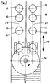
Gemäß Figur 1 werden flachliegende Folienschläuche 1, 2 von Haspelin
3, 4 über Umlenkrollen 5, 6. Öffnungsdornen 7, 8 zugeführt.
Mit Hilfe je eines Reibräderpaares 9, 10, welches mit Hilfsrollen
11, 12 zusammenarbeitet wird der jeweilige Folienschlauch 1 bzw.
2 über den Öffnungsdorn 7 bzw. 8 geführt und am Ende des Öffnungsdorns
über einen jeweiligen freien Zwischenraum 13. 14 auf
ein aus Deckel und Hülse bestehendes Gefäß 15 bzw. 16
aufgeschoben. According to Figure 1, flat-lying
Die Gefäße 15, 16 stehen jeweils auf Förderbändern 17 bzw. 18 die
sich in ihrer Fortschrittsrichtung aus der Zeichnungsebene senkrecht
zu dieser aus dieser heraus oder in diese hineinbewegen.The
Zunächst wird gemäß Figur 1 angenommen, daß während des
Überstreifens der Folienschläuche 1 und 2 über die Gefäße 15, 16
die Offnungsdorne 7, 8 synchron mit den Förderbandern 17, 18 sich
entlang bewegen.First, it is assumed according to Figure 1 that during the
Slip on the
Zwischen den beiden Öffnungsdornen 7, 8 ist nunmehr ein um eine
parallel zu den Achsen des Öffnungsdorne sich erstreckende
Antriebsachse 19 rotierendes von dieser sich wegerstreckendes
senkrecht zur Drehachse schneidendes in einer Ebene verlaufendes
Bauteil 20 vorgesehen, welches in Pfeilrichtung 21 rotiert.Between the two opening
Nach Erreichen einer Endlage 22, 23 in Bezug zum Gefäß 15 wird
die Rotation der Haspeln 3, 4 unterbrochen und es werden die mit
einem Folienschlauch überzogenen Gefäße dem in einer Ebene verlaufenden
Bauteil 20 zugeführt. Bei dem Bauteil 20 handelt es
sich gemäß Ausführungsbeispiel um ein Kreissägeblatt 24; welches
von einem Antriebsmotor 25 über eine Welle 26 angetrieben wird.After reaching an
Durch das Fortschreiten der Förderbänder 17, 18 und die Rotation
des Kreissägeblatts 24 werden während des Fortschreitens gleichzeitig
beide Folienschläuche im Bereich des freien Zwischenraums
aufgeteilt. By the progress of the
Nach Durchtrennen der Folienschläuche werden die nun mit Folienschlauch
überzogenen Gefäße 15, 16 eine Sleeveinrichtung, welche
nicht dargestellt ist, zugeführt und dort mittels Aufschrumpfen
so gesichert, daß ein unbeabsichtigtes Öffnen der aus Deckel und
Hülse bestehenden Gefäße ohne Zerstörung des Folienschlauchs
nicht geschehen kann.After cutting the film tubes, they are now covered with a film tube
coated
Gemäß Figur 2 wird anschließend das Förderband 17 und 18 gemäß
Doppelpfleil 27 zurückgeschwenkt, sodaß das nächste Paar Gefäße
15, 16 gleichzeitig in Wirkverbindung mit dem Öffnungsdornen 7, 8
gebracht werden kann und somit werden erneut die Gefäße 15, 16
mit Folienschlauch während des Fortschreitens der Förderbänder
17, 18 versehen.According to Figure 2, the
Zur Erhöhung der Durchsatzgeschwindigkeit und damit Erhöhung des
Ausstoßes ist es jedoch mittels der Erfindung auch denkbar, das
Kreissägeblatt 24 um seinen Antriebsmotor 25 pendelnd
aufzuhängen. Damit wird die Möglichkeit geschaffen Abstände 28,
29 zwischen den Gefäßen 15, 16 noch weiter zu verkürzen.To increase the throughput speed and thus increase the
Output, however, it is also conceivable by means of the invention that
Circular saw
Anstelle des Kreissägeblatts 24 wird gemäß Figur 3 eine Bandsäge
30 benutzt, welche über Umlenkscheiben 31, 32 ein Band 33 trägt.Instead of the
Im Zwischenraum zwischen den Umlenkscheiben 31, 32 ist eine weitere
Fördereinrichtung 34 vorgesehen auf welche beispielsweise
drei Gefäße nebeneinander angeordnet sind. Jedem dieser Gefäße
ist ein Öffnungsdorn und eine Haspel mit Folienschlauch zugeordnet. Another is in the space between the
Sind die Gefäße mit Folienschlauchabschnitten versehen, wird
durch Bewegen des Bandes 33 in Doppelpfleilrichtung 35 ein
Auftrennen des jeweiligen Folienschlauchs im freien Zwischenraum
zwischen Õffnungsdorn und jeweiligem Gefäß geschehen.If the tubes are provided with film tube sections,
by moving the
Damit läßt sich ein noch höherer Durchsatz von zu sleevenden
Geräten auch bei verschiedener Höhe der Gefäße allein durch
Absenken oder Anheben der weiteren Fördereinrichtung 34
erfindungsgemäß erreichen.This enables an even higher throughput of sleeves to be sleeved
Devices even at different heights of the vessels
Lowering or raising the
Gleiches gilt auch bei einer Anlieferung von zu sleevenden
Gefäßen in bunter Folge, in Bezug auf die Höhe dieser Gefäße,
wenn, wie in Figur 1 durch Doppelpfeile 39, 40 dargestellt die
Förderbänder 17, 18 in Ihrer Höhe wechselweise gegenüber der
feststehenden horizontalschneidenden Kreissäge 24 angeordnet
sind.The same applies to the delivery of items to be sleeved
Vessels in colorful order, in terms of the height of these vessels,
if, as shown in Figure 1 by
In Abhängigkeit einer schematisch dargestellten Abtasteinrichtung
41, bei welcher die Höhe des jeweiligen Gefäßes abgetastet wird,
wird in Verbindung mit der in ihrer Arbeitshöhe bezogen auf die
Öffnungsdorne 7, 8 festliegenden Kreissäge 24 rechtzeitig ein
Steuerbefehl an die Fördereinrichtung 17 bzw. 18 weitergegeben,
sodaß die Fördereinrichtung 17, 18 gegenüber ihrer Normalhöhe vor
Einleiten des Schneidvorgangs rechtzeitig angehoben oder
abgesenkt wird. Depending on a schematically represented scanning device
41, at which the height of the respective vessel is scanned,
is used in conjunction with the working height in relation to the
Werden auch in bunter Folge Gefäße verschiedenen Durchmessers
vorbereitet, so kann auf einem um eine Karussellachse 43 sich
drehendes Karussell, auf welchem auf Haspeln angeordnete
Folienschläuche vorgegebener Breite angeordnet sind durch
Weiterbewegen des Karussells entsprechend der erforderlichen
Durchmesserkonfiguration des einzelnen Gefäßes jeweils der
richtige Folienschlauch ausgewählt werden und durch Drehen des
nicht dargestellten Karussells um die Drehachse 43 in Verbindung
mit dem zu sleevenden Gefäß gebracht werden.Are also vessels of different diameters in a colorful sequence
prepared, so can on a
Damit läßt sich ohne zeitaufwendigen Umbau eine große Palette von Gefäßen, welche im Durchmesser und in der Höhe variieren für ein Sleeven vorbereiten, ohne daß zeitaufwendiges Umbauen erforderlich wird.This allows a large range of Vessels that vary in diameter and height for one Prepare sleeves without time-consuming conversions is required.
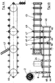
Die in Figur 4a in der Ansicht dargestellte Ausgestaltung des Erfindungsgegenstandes und die in Figur 4b in der Draufsicht dargestellte Anordnung dient für schmale längliche Gegenstände. beispielsweise Lippenstifte.The embodiment of the view shown in Figure 4a Subject of the invention and that in Figure 4b in plan view arrangement shown serves for narrow elongated objects. for example lipsticks.
Ein erster Transporteur 44 arbeitet mit einer Kreissäge 24
zusammen. Hierbei wird über den Öffnungsdorn 8 der Folienschlauch
2 geöffnet und einem Hilfsdorn 46 zugeführt. Durch das Fortschreiten
des Tranporteurs 44 gegen die feststehende Kreissäge 24
bei Mitbewegen des Dorns 8 und des Folienschlauchs 2, wird der
Folienschlauch 2 abgetrennt, sodaß das Folienschlauchstück auf
dem Hilfsdorn 46 verbleibt.A
Hinter der Kreissäge 24 ist nun ein weiterer Transporteur 45
angeordnet. welcher beispielsweise aus einer nicht dargestellten
Fertigungslinie kommende fertig konfektionierte Lippenstifte 47
abzieht und auf dem weiteren Transporteur 45 lagerichtig
positioniert. Hierbei besitzt sowohl der erste Transporteur 44
Gegenhalter 48 und auch der weitere Transporteur 45 Gegenhalter
48.Behind the
Die Gegenhalter 48 treten dann in Funktion, wenn Folienschläuche
über den Hilfsdorn 46 oder beispielsweise über den Lippenstift 47
geschoben werden. Im Falle des Aufschiebens von Folienschlauchstücken
49 auf den Lippenstift 47 wird über eine schematisch dargestellte
Aufschiebeeinrichtung 50 während des synchronen Transports
des ersten Transporteurs 44 mit dem weiteren Transporteur
45 der Aufschubvorgang beendet, während der nunmehr freigewordene
Hilfsdorn 46 wieder an den Anfang des Transporteurs zurücktransportiert
wird, während gleichzeitig vom weiteren Transporteur 45,
der nunmehr mit einem Folienschlauchstück 49 versehene Lippenstift
47 einer nicht dargestellten Sleeveinrichtung zugeführt
wird.The
Wird an Stelle eines Kreissägeblatts 24 um den ersten Transporteur
44 eine Bandsäge entsprechend Figur 3 angeordnet, so wird
beispielsweise jeder gerade Gegenhalter mit dem weiteren Transporteur
45 zusammenwirken, während jeder ungerade Gegenhalter mit
einem nicht dargestellten noch weiteren Transporteur auf der anderen
Seite des ersten Transporteurs 44 angeordnet, zusammenarbeitet.
Damit läßt sich auch hier eine beachtliche Erhöhung des
Durchsatzes von zu sleevenden Bauteilen erreichen und es läßt
sich auch in einfachster Form ein bunte Reihe verschieden langer
und verschiedenen Durchmesser besitzender schlanker Bauteile, wie
Lippenstifte oder Kugelschreiber, für einen Sleevvorgang
vorbereiten.Instead of a
In Figur 4a ist in schematischer Darstellung eine Rutsche 50
dargstellt, aus welcher fertig konfektionierte Lippenstifte, beispielsweise
auf dem weiteren Transporteur 45 ausgerichtet, an
Gegenhaltern anliegend aufgebracht werden.A
Claims (12)
Applications Claiming Priority (2)
| Application Number | Priority Date | Filing Date | Title |
|---|---|---|---|
| DE19737689 | 1997-08-29 | ||
| DE19737689A DE19737689A1 (en) | 1997-08-29 | 1997-08-29 | Method for severing an open piece of film tube and device for carrying out the method |
Publications (3)
| Publication Number | Publication Date |
|---|---|
| EP0899082A2 true EP0899082A2 (en) | 1999-03-03 |
| EP0899082A3 EP0899082A3 (en) | 1999-12-01 |
| EP0899082B1 EP0899082B1 (en) | 2002-11-06 |
Family
ID=7840560
Family Applications (1)
| Application Number | Title | Priority Date | Filing Date |
|---|---|---|---|
| EP98115604A Expired - Lifetime EP0899082B1 (en) | 1997-08-29 | 1998-08-19 | Process and apparatus for severing open sections of tubular webs |
Country Status (3)
| Country | Link |
|---|---|
| EP (1) | EP0899082B1 (en) |
| DE (2) | DE19737689A1 (en) |
| ES (1) | ES2186954T3 (en) |
Cited By (2)
| Publication number | Priority date | Publication date | Assignee | Title |
|---|---|---|---|---|
| EP1177979A3 (en) * | 2000-08-03 | 2002-11-06 | Lortz, Hans-Joachim, c/o LogicPAK Maschinenbau Service und Vertriebs GmbH | Method of sliding tubular films on elongate objects and processing apparatus for carrying out the method |
| US6955033B2 (en) | 2002-07-24 | 2005-10-18 | Hans-Joachim Lortz | Method of pushing tubular films onto elongate objects and processing apparatus for implementing the method |
Families Citing this family (6)
| Publication number | Priority date | Publication date | Assignee | Title |
|---|---|---|---|---|
| DE502006006773D1 (en) | 2005-12-16 | 2010-06-02 | Lortz Hans Joachim | Cutting device for a film tube |
| DE102007028003A1 (en) | 2007-06-14 | 2008-12-18 | Hans-Joachim Lortz | Hose segments separating device, has circular cutter with rotating blade supported on rim such that cutter extends into borehole by rotation of rim, where cutter extends into/from borehole during rotation of rim |
| DE102008064550A1 (en) | 2008-12-31 | 2010-07-01 | Hans-Joachim Lortz | Device for cutting tube segments of endless sleeve of e.g. bottles, has blade controlled by rotation speed difference of one rim to another rim, and linear movement unit for linearly moving rims back and forth along plane |
| DE102010019802A1 (en) | 2010-05-06 | 2011-11-10 | Schuster Maschinenbau Gmbh | Device for drawing braided tube material on work piece, has conveyer system having gripping equipment for gripping tube material, where gripping equipment is displaceable in drawing direction |
| DE202013105243U1 (en) * | 2013-11-20 | 2015-02-27 | Krones Ag | Deflection device for a film tube and control device for a deflection device |
| DE102021115738A1 (en) | 2021-06-17 | 2022-12-22 | Bruno Müller | tubing coating device |
Citations (5)
| Publication number | Priority date | Publication date | Assignee | Title |
|---|---|---|---|---|
| US4179863A (en) * | 1977-08-03 | 1979-12-25 | Jacques Fresnel | Apparatus for sectioning thermoplastic sheath and placing resulting sleeves around containers |
| US5001887A (en) * | 1988-02-25 | 1991-03-26 | Krones Ag Hermann Kronseder Maschinenfabrik | Method for applying a shrink sleeve to the closure end of a container and apparatus for performing such method |
| US5531858A (en) * | 1995-01-20 | 1996-07-02 | Hong; Chin-Tan | Shrinkable label inserting machine |
| FR2730210A1 (en) * | 1995-02-02 | 1996-08-09 | Novatech Sarl | Machine for placing net sleeves on objects |
| US5566527A (en) * | 1995-05-23 | 1996-10-22 | H.G. Kalish, Inc. | Apparatus for applying a heat-shrinkable band to the neck of a container |
Family Cites Families (7)
| Publication number | Priority date | Publication date | Assignee | Title |
|---|---|---|---|---|
| US2765607A (en) * | 1953-07-21 | 1956-10-09 | John G Aguilar | Band applying device |
| US2846835A (en) * | 1955-11-14 | 1958-08-12 | Burton Machine Corp John | Band applying device and method |
| US4048883A (en) * | 1976-09-16 | 1977-09-20 | Lecrone Dale S | Band-type roll slicing machine |
| DE3208234C2 (en) * | 1982-03-06 | 1984-02-16 | Krones Ag Hermann Kronseder Maschinenfabrik, 8402 Neutraubling | Device for placing hose sections made of plastic film or the like. on vessels |
| NL8204315A (en) * | 1982-11-08 | 1984-06-01 | Intermatic Machines B V | Device for spreading a tube of flexible material. |
| CA1224754A (en) * | 1983-07-05 | 1987-07-28 | Robert J. Burmeister | Method of applying plastic labels on glass containers |
| DE8907040U1 (en) * | 1989-06-08 | 1989-09-14 | Kuehnemuth, Gerhard, 3441 Berkatal, De |
-
1997
- 1997-08-29 DE DE19737689A patent/DE19737689A1/en not_active Withdrawn
-
1998
- 1998-08-19 ES ES98115604T patent/ES2186954T3/en not_active Expired - Lifetime
- 1998-08-19 DE DE59806162T patent/DE59806162D1/en not_active Expired - Lifetime
- 1998-08-19 EP EP98115604A patent/EP0899082B1/en not_active Expired - Lifetime
Patent Citations (5)
| Publication number | Priority date | Publication date | Assignee | Title |
|---|---|---|---|---|
| US4179863A (en) * | 1977-08-03 | 1979-12-25 | Jacques Fresnel | Apparatus for sectioning thermoplastic sheath and placing resulting sleeves around containers |
| US5001887A (en) * | 1988-02-25 | 1991-03-26 | Krones Ag Hermann Kronseder Maschinenfabrik | Method for applying a shrink sleeve to the closure end of a container and apparatus for performing such method |
| US5531858A (en) * | 1995-01-20 | 1996-07-02 | Hong; Chin-Tan | Shrinkable label inserting machine |
| FR2730210A1 (en) * | 1995-02-02 | 1996-08-09 | Novatech Sarl | Machine for placing net sleeves on objects |
| US5566527A (en) * | 1995-05-23 | 1996-10-22 | H.G. Kalish, Inc. | Apparatus for applying a heat-shrinkable band to the neck of a container |
Cited By (2)
| Publication number | Priority date | Publication date | Assignee | Title |
|---|---|---|---|---|
| EP1177979A3 (en) * | 2000-08-03 | 2002-11-06 | Lortz, Hans-Joachim, c/o LogicPAK Maschinenbau Service und Vertriebs GmbH | Method of sliding tubular films on elongate objects and processing apparatus for carrying out the method |
| US6955033B2 (en) | 2002-07-24 | 2005-10-18 | Hans-Joachim Lortz | Method of pushing tubular films onto elongate objects and processing apparatus for implementing the method |
Also Published As
| Publication number | Publication date |
|---|---|
| EP0899082B1 (en) | 2002-11-06 |
| ES2186954T3 (en) | 2003-05-16 |
| EP0899082A3 (en) | 1999-12-01 |
| DE19737689A1 (en) | 1999-03-04 |
| DE59806162D1 (en) | 2002-12-12 |
Similar Documents
| Publication | Publication Date | Title |
|---|---|---|
| DE3119657C2 (en) | Method and machine for the production of packaging units | |
| EP0140301B1 (en) | Method and device for enveloping packages or bundles in stretch-foil | |
| DE2321457A1 (en) | METHOD AND MACHINE FOR MANUFACTURING LONGITUDINAL SHELLS FROM PLASTIC FILM, E.G. FOR WALLPAPER ROLLS | |
| EP0312877A2 (en) | Method and device for the production of package cuts | |
| DE3724196A1 (en) | DEVICE FOR APPLYING SOLVENTS AND THE LIKE | |
| EP2719627A1 (en) | Method and device for wrapping a stack of goods with a film | |
| EP0144009A2 (en) | Packaging machine with a stock holder for rolls | |
| DE60217244T2 (en) | Device for positioning a sleeve | |
| EP0899082B1 (en) | Process and apparatus for severing open sections of tubular webs | |
| DE2322377A1 (en) | PROCEDURE FOR PACKAGING ITEMS AND MACHINE FOR CARRYING OUT THE PROCEDURE | |
| WO2017167357A1 (en) | Apparatus and method for packaging piece goods and in particular containers | |
| EP3281878B1 (en) | Device for wrapping a stack of goods with a hose hood and method of changing the hose film store in such a device | |
| DE3933952C2 (en) | ||
| EP1575831B1 (en) | System and method for packaging containers, particularly bottle containers | |
| DE2149297A1 (en) | Process for coating cylindrical objects and device for carrying out the process | |
| DE1561434C3 (en) | Process for the continuous manufacture of carrier bags or pouches with two handles and a machine for carrying out the process | |
| EP1074472B1 (en) | Apparatus for transporting web rolls of packaging material | |
| DE2759443C2 (en) | Method and apparatus for applying heat-shrinkable sleeves to the periphery of containers | |
| DE455263C (en) | Device for continuous feeding of the paper web and separation of the individual paper lengths, especially on wrapping machines | |
| DE2716391B2 (en) | Method for manufacturing and packaging filter cigarettes and device for carrying out the method | |
| EP1177979B1 (en) | Method of sliding tubular films on elongate objects and processing apparatus for carrying out the method | |
| DE202016105661U1 (en) | Rotation shrinking device | |
| DE19908395C2 (en) | Process for covering flat bodies of small thickness with shrinkable film tube sections and processing device for carrying out the process | |
| CH627698A5 (en) | Labelling apparatus with continuously working kinematics | |
| DE3633036A1 (en) | Conveying device for conveying and depositing workpieces which are easily damaged during handling |
Legal Events
| Date | Code | Title | Description |
|---|---|---|---|
| PUAI | Public reference made under article 153(3) epc to a published international application that has entered the european phase |
Free format text: ORIGINAL CODE: 0009012 |
|
| AK | Designated contracting states |
Kind code of ref document: A2 Designated state(s): DE ES FR GB IT NL |
|
| AX | Request for extension of the european patent |
Free format text: AL;LT;LV;MK;RO;SI |
|
| PUAL | Search report despatched |
Free format text: ORIGINAL CODE: 0009013 |
|
| AK | Designated contracting states |
Kind code of ref document: A3 Designated state(s): AT BE CH CY DE DK ES FI FR GB GR IE IT LI LU MC NL PT SE |
|
| AX | Request for extension of the european patent |
Free format text: AL;LT;LV;MK;RO;SI |
|
| 17P | Request for examination filed |
Effective date: 19991208 |
|
| AKX | Designation fees paid |
Free format text: DE ES FR GB IT NL |
|
| 17Q | First examination report despatched |
Effective date: 20001204 |
|
| GRAG | Despatch of communication of intention to grant |
Free format text: ORIGINAL CODE: EPIDOS AGRA |
|
| GRAG | Despatch of communication of intention to grant |
Free format text: ORIGINAL CODE: EPIDOS AGRA |
|
| GRAH | Despatch of communication of intention to grant a patent |
Free format text: ORIGINAL CODE: EPIDOS IGRA |
|
| GRAH | Despatch of communication of intention to grant a patent |
Free format text: ORIGINAL CODE: EPIDOS IGRA |
|
| GRAA | (expected) grant |
Free format text: ORIGINAL CODE: 0009210 |
|
| AK | Designated contracting states |
Kind code of ref document: B1 Designated state(s): DE ES FR GB IT NL |
|
| REG | Reference to a national code |
Ref country code: GB Ref legal event code: FG4D Free format text: NOT ENGLISH |
|
| REF | Corresponds to: |
Ref document number: 59806162 Country of ref document: DE Date of ref document: 20021212 |
|
| GBT | Gb: translation of ep patent filed (gb section 77(6)(a)/1977) |
Effective date: 20030210 |
|
| REG | Reference to a national code |
Ref country code: ES Ref legal event code: FG2A Ref document number: 2186954 Country of ref document: ES Kind code of ref document: T3 |
|
| ET | Fr: translation filed | ||
| PLBE | No opposition filed within time limit |
Free format text: ORIGINAL CODE: 0009261 |
|
| STAA | Information on the status of an ep patent application or granted ep patent |
Free format text: STATUS: NO OPPOSITION FILED WITHIN TIME LIMIT |
|
| 26N | No opposition filed |
Effective date: 20030807 |
|
| REG | Reference to a national code |
Ref country code: FR Ref legal event code: PLFP Year of fee payment: 18 |
|
| REG | Reference to a national code |
Ref country code: FR Ref legal event code: PLFP Year of fee payment: 19 |
|
| PGFP | Annual fee paid to national office [announced via postgrant information from national office to epo] |
Ref country code: NL Payment date: 20160824 Year of fee payment: 19 |
|
| PGFP | Annual fee paid to national office [announced via postgrant information from national office to epo] |
Ref country code: DE Payment date: 20160831 Year of fee payment: 19 Ref country code: GB Payment date: 20160824 Year of fee payment: 19 Ref country code: IT Payment date: 20160823 Year of fee payment: 19 |
|
| PGFP | Annual fee paid to national office [announced via postgrant information from national office to epo] |
Ref country code: FR Payment date: 20160825 Year of fee payment: 19 |
|
| PGFP | Annual fee paid to national office [announced via postgrant information from national office to epo] |
Ref country code: ES Payment date: 20160727 Year of fee payment: 19 |
|
| REG | Reference to a national code |
Ref country code: DE Ref legal event code: R119 Ref document number: 59806162 Country of ref document: DE |
|
| REG | Reference to a national code |
Ref country code: NL Ref legal event code: MM Effective date: 20170901 |
|
| GBPC | Gb: european patent ceased through non-payment of renewal fee |
Effective date: 20170819 |
|
| REG | Reference to a national code |
Ref country code: FR Ref legal event code: ST Effective date: 20180430 |
|
| PG25 | Lapsed in a contracting state [announced via postgrant information from national office to epo] |
Ref country code: NL Free format text: LAPSE BECAUSE OF NON-PAYMENT OF DUE FEES Effective date: 20170901 |
|
| PG25 | Lapsed in a contracting state [announced via postgrant information from national office to epo] |
Ref country code: DE Free format text: LAPSE BECAUSE OF NON-PAYMENT OF DUE FEES Effective date: 20180301 Ref country code: GB Free format text: LAPSE BECAUSE OF NON-PAYMENT OF DUE FEES Effective date: 20170819 |
|
| PG25 | Lapsed in a contracting state [announced via postgrant information from national office to epo] |
Ref country code: IT Free format text: LAPSE BECAUSE OF NON-PAYMENT OF DUE FEES Effective date: 20170819 Ref country code: FR Free format text: LAPSE BECAUSE OF NON-PAYMENT OF DUE FEES Effective date: 20170831 |
|
| REG | Reference to a national code |
Ref country code: ES Ref legal event code: FD2A Effective date: 20181025 |
|
| PG25 | Lapsed in a contracting state [announced via postgrant information from national office to epo] |
Ref country code: ES Free format text: LAPSE BECAUSE OF NON-PAYMENT OF DUE FEES Effective date: 20170820 |