EP0898894B1 - Semiautomatic pig thigt deboner and deboning process for pig thigh using same - Google Patents
Semiautomatic pig thigt deboner and deboning process for pig thigh using same Download PDFInfo
- Publication number
- EP0898894B1 EP0898894B1 EP98115553A EP98115553A EP0898894B1 EP 0898894 B1 EP0898894 B1 EP 0898894B1 EP 98115553 A EP98115553 A EP 98115553A EP 98115553 A EP98115553 A EP 98115553A EP 0898894 B1 EP0898894 B1 EP 0898894B1
- Authority
- EP
- European Patent Office
- Prior art keywords
- cutting
- section
- meat
- processing apparatus
- pig thigh
- Prior art date
- Legal status (The legal status is an assumption and is not a legal conclusion. Google has not performed a legal analysis and makes no representation as to the accuracy of the status listed.)
- Expired - Lifetime
Links
- 210000000689 upper leg Anatomy 0.000 title claims description 86
- 238000000034 method Methods 0.000 title claims description 26
- 230000008569 process Effects 0.000 title claims description 16
- 235000013372 meat Nutrition 0.000 claims description 98
- 238000005520 cutting process Methods 0.000 claims description 90
- 238000012545 processing Methods 0.000 claims description 86
- 230000007246 mechanism Effects 0.000 claims description 75
- 210000000988 bone and bone Anatomy 0.000 claims description 45
- 210000002391 femur head Anatomy 0.000 claims description 25
- 210000001699 lower leg Anatomy 0.000 claims description 23
- 210000002082 fibula Anatomy 0.000 claims description 22
- 210000001981 hip bone Anatomy 0.000 claims description 22
- 210000003423 ankle Anatomy 0.000 claims description 15
- 210000002414 leg Anatomy 0.000 claims description 13
- 210000001519 tissue Anatomy 0.000 claims description 13
- 210000001762 upper extremity of fibula Anatomy 0.000 claims description 11
- 238000000926 separation method Methods 0.000 claims description 10
- 230000008859 change Effects 0.000 claims description 8
- 210000003205 muscle Anatomy 0.000 claims description 6
- 230000007723 transport mechanism Effects 0.000 claims description 6
- 230000001360 synchronised effect Effects 0.000 claims description 4
- 238000012790 confirmation Methods 0.000 claims 1
- 238000005259 measurement Methods 0.000 description 10
- 210000002239 ischium bone Anatomy 0.000 description 6
- 230000010355 oscillation Effects 0.000 description 5
- 101000585359 Homo sapiens Suppressor of tumorigenicity 20 protein Proteins 0.000 description 4
- 102100029860 Suppressor of tumorigenicity 20 protein Human genes 0.000 description 4
- 210000003692 ilium Anatomy 0.000 description 4
- 210000002303 tibia Anatomy 0.000 description 4
- 102100035353 Cyclin-dependent kinase 2-associated protein 1 Human genes 0.000 description 3
- 101000760620 Homo sapiens Cell adhesion molecule 1 Proteins 0.000 description 3
- 101000737813 Homo sapiens Cyclin-dependent kinase 2-associated protein 1 Proteins 0.000 description 3
- 101001139126 Homo sapiens Krueppel-like factor 6 Proteins 0.000 description 3
- 101000710013 Homo sapiens Reversion-inducing cysteine-rich protein with Kazal motifs Proteins 0.000 description 3
- 238000010586 diagram Methods 0.000 description 3
- 101000911772 Homo sapiens Hsc70-interacting protein Proteins 0.000 description 2
- 101000661816 Homo sapiens Suppression of tumorigenicity 18 protein Proteins 0.000 description 2
- 101000661807 Homo sapiens Suppressor of tumorigenicity 14 protein Proteins 0.000 description 2
- 210000000078 claw Anatomy 0.000 description 2
- 238000001514 detection method Methods 0.000 description 2
- 238000006073 displacement reaction Methods 0.000 description 2
- 108090000237 interleukin-24 Proteins 0.000 description 2
- 239000002184 metal Substances 0.000 description 2
- 210000000588 acetabulum Anatomy 0.000 description 1
- 230000008878 coupling Effects 0.000 description 1
- 238000010168 coupling process Methods 0.000 description 1
- 238000005859 coupling reaction Methods 0.000 description 1
- 230000000694 effects Effects 0.000 description 1
- 230000005484 gravity Effects 0.000 description 1
- 210000000527 greater trochanter Anatomy 0.000 description 1
- 239000000463 material Substances 0.000 description 1
- 238000011084 recovery Methods 0.000 description 1
- 230000009467 reduction Effects 0.000 description 1
- 239000002699 waste material Substances 0.000 description 1
Images




Classifications
-
- A—HUMAN NECESSITIES
- A22—BUTCHERING; MEAT TREATMENT; PROCESSING POULTRY OR FISH
- A22C—PROCESSING MEAT, POULTRY, OR FISH
- A22C17/00—Other devices for processing meat or bones
- A22C17/0093—Handling, transporting or packaging pieces of meat
-
- A—HUMAN NECESSITIES
- A22—BUTCHERING; MEAT TREATMENT; PROCESSING POULTRY OR FISH
- A22C—PROCESSING MEAT, POULTRY, OR FISH
- A22C17/00—Other devices for processing meat or bones
- A22C17/004—Devices for deboning meat
Definitions
- the present invention relates to a semiautomatic pig thigh deboner and a deboning process for a pig thigh using the same in which removing of meat from its bone is efficiently performed.
- EP-A-0 590 733 and EP-A-0 763 326 each disclose a device for holding the leg of a slaughtered animal, and a method for deboning the leg.
- the device disclosed in the first-mentioned document has a ball bearing allowing the leg to be freely rotated and inclined. Both methods rely mainly on manual labour.
- Preferred embodiments are a deboning process for a pig thigh using the deboner, in which a meat stripping position, and cutting and cutting-in positions by a cutter are selected so as to be most optimal in performing and a more secured meat stripping operation is realized.
- Embodiments of a structure of a deboner and a deboning process of the present invention will be sequentially described.
- All operations of the deboning process are performed in a condition where a work is hung in the air as it is gripped and the operations are thereby performed under as small an influence as possible of its self weight.
- a manual operation is limited to an important cutting-in operation and an organic tissue around a joint is cut-in or cut by a cutter which is pressed to the work while the work is rotated through a necessary angle.
- a semi-automatic pig thigh deboner in which a pig thigh held by gripping on a transport line is sequentially deboned starting from a hind shank, comprises: the transport line along which a plurality of work stations are provided; transporting/processing means for transporting the pig thigh through the work stations sequentially and processings are respectively performed on the pig thigh at the work stations under application of driving forces for stripping of the meat section, rotating and vertical movement of the pig thigh; driving means comprising a meat stripping mechanism, a vertical movement mechanism and a rotating mechanism for outputting the driving forces for stripping of the meat section, rotating and vertical movement of the pig thigh, the driving means connecting to the transport/processing means at each of the work stations; cutting means for cutting an organic tissue away from a bone section exposed by stripping of the meat section; and detecting/computing means for detecting the base positions of heads of a fibula and a femur.
- the transport/processing means preferably comprises: a clamper to grip the ankle side section of a pig thigh as a work; and a transport mechanism including a boat-shaped engaging member mounted on a transport frame through which a connecting shaft which supports the clamper in a freely inclining manner is inserted.
- the boat-shaped engaging member is engaged with a straddle joint mounted at the lower section of a rotary vertically moving shaft of the vertical movement mechanism before the boat-shaped engaging member enter a station and constitutes a transfer joint to transfer two driving forces of rotating and vertical movement to the connecting shaft by means of the driving means.
- the driving means which outputs driving forces of stripping of the meat section, rotating and vertical movement of the pig thigh preferably comprises: the vertical movement mechanism which vertically moves the connecting shaft through the boat-shaped engaging member when the work is kept stopped; and a rotating mechanism to rotate the connection shaft and a driving shaft for squeezing of a meat separator constituting a stripping mechanism in synchronization with each other.
- a deboning process for a pig thigh in which after predetermined preliminary processing, the pig thigh is transported through a plurality of work stations and processed in each of the stations and thereby the pig thigh held by gripping on a transport line is deboned sequentially from a hind shank, and which comprises:
- a work receives preliminary processing in which there is used a transport line along which a plurality of work stations are provided, a pig thigh (hereinafter simply referred to as work) is held by gripping and sequentially transported through the respective work stations and at each work station, the work takes a inclined position and removal of a hip bone, a sacrum and caudal vertebrae and cutting-in before and after deboning are performed, and the work further receives automatic deboning processing for which there is further used a transport/processing means in which stripping of the meat section, rotating and vertical movement of the work are performed with the help of driving means at respective work stations, whereby the present invention totally enables deboning to be performed in a hygienic and semi-automatic manner almost without any manual procedures.
- the transport/processing means intermittently transport a work while holding by gripping to the respective work stations along the transport line, and at each work station, an engaging member and a straddle joint are coupled with each other and the gripped work is subjected to stripping of the meat section, rotating and vertical movement of the work by the driving means.
- a vertical movement mechanism for vertically moving the work is in a fine manner controlled by a servo motor
- a rotating mechanism for rotating the work has functions of home position driving, deceleration stoppage at a predetermined position, and locking at stop position, the work can vertically moved according to a stripped amount by a meat separator in each work station and a cutting position of a cutter can be set with certainty at a predetermined position, whereby precision in a cutting width is increased.
- a cutter mechanism In the case of cutting of the interior of the work or an organic tissue, a cutter mechanism has a feed mechanism from a waiting position to a cutting position under a freely adjustable pressure and the work is adapted to rotate through a predetermined angle with respect to the cutter mechanism, whereby the organic tissue at a fixed position around a bone section can be cut not only with certainty but at a fixed width.
- detecting/computing means for detecting the base positions of heads of fibula and femur, with use of computed results by the means two reference positions are set and a stripping position for a meat section in a later step can be predicted with accuracy and thereby deboning can be performed with efficiency.
- a clamper does not fail to be returned to its previous position after it is raised by the vertical movement mechanism and coupling or disengaging of the straddle joint and the boat-shaped engaging member is in a secured manner performed without any interference from others.
- the rotating mechanism of the driving means has the functions of home position driving and deceleration stoppage at a predetermined position, and thereby rotation control of the clamper and the meat separator can in a secured manner be performed, a cutting position and a cutting width by means of the cutting mechanism can be controlled with accuracy.
- the meat separator comprises squeezing plates each with a U-shaped concavity which are driven by squeezing mechanism under a freely adjustable pressure
- the meat separator can be adapted to a change in shape of a bone section so as to achieve perfect stripping when the meat section is stripped.
- the bone and meat sections of the work can rotate at equal speed when the meat section of the work and an organic tissue is cut or cut in by means of the cutting mechanism, which makes smooth cutting realized.
- the cutting means has a structure which has the feed mechanism under a freely adjustable pressure, the cutter can easily be fixed at a cutting position and perfect cutting can be realized. Besides, since a structure which can control a rotational angle of the work through which the cutter contacts is adopted, making sure of a given cutting width and setting of a given cutting position can be performed.
- a horizontal circular blade is preferably used.
- the detecting/computing means when detecting the base position of a fibula head comprises a sensor section which, in a sliding and inclined manner, contacts with the bone section exposed in company with moving down of the separator which strips off the meat section from the bone section and has a structure that detection and computation of a position can be performed in correspondence to a shape change of the bone section in contact, while, since the detecting/computing means when detecting the base end of a femur head has a measuring section of a structure that a connecting shaft which is connected to the clamper is further connected to a vertical movement section driven by an air cylinder and a rapid slow-down of the femur head in the upward movement by the squeezing section of the separator can be detected and computed by an encoder mounted on the air cylinder, the base positions of heads of the fibula and femur which are conspicuous in shape change can be detected and computed with certainty.
- the preliminary processing apparatus has a structure that waste of labor is suppressed to its minimum, the work keeps a downwardly inclined position at an inclination of about 30 degrees and thus manual cutting-in can be performed at the minimal labor. Thereby, deboning with the help of the hip bone, a sacrum and caudal vertebrae removing apparatus and automatic deboning in a later stage can be realized.
- 30 indicates a pig thigh, 31 a preliminary processing apparatus, 32 a full automatic deboner, 33 a transport chain, 33a the transport rails, 34 transport/processing means, 35 a clamper, 36 a hip bone, a sacrum and caudal vertebrae removing apparatus, 37 a inclining mechanism, 40 an operator, 41 a coccyx, 42 an ischium, 43 a hip bone, 45 a hind shank, 46 a femur, 50 a meat separator, 51 a driving shaft, 52: squeezing members, 53 an actuator, 54, 65 chain transfer mechanisms, 55 a cutter mechanism, 56 a rotary circular blade, 58 a feed/retreat cylinder, 59: an oscillation cylinder, 60: a carriage, 61: a rectangular member, 62 a connecting shaft, 63 a boat-shaped engaging member, 64 a rotary vertically moving shaft, 64a a straddle joint, 67 a vertical movement mechanism, 69
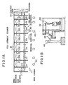
- FIG. 1(A) is a front view showing a schematic constitution of a semi-automatic deboning process for deboning a pig thigh and FIG. 1(B) is a side view of the same
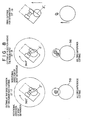
- FIG. 2 is views showing conditions of processing steps in a preliminary processing apparatus of FIG. 1
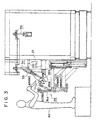
- FIG. 3 is a condition of stripping a hip bone at ST 5 of FIG. 1
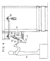
- FIG. 4 is a view showing a cutting-in operation of FIG. 2
- FIG. 5 is a view showing conditions of processing steps in a full automatic processing apparatus of FIG. 1
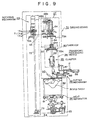
- FIG. 9 is a view showing how a driving means is connected to a transport/processing means of FIG. 1, FIG.
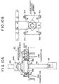
- FIG. 10(A) is a carriage constituting a transport mechanism running on transport rails while hanging a clamper of FG.
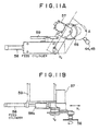
- FIG. 11 is a side view showing a schematic structure of the meat separator constituting meat stripping mechanism of FIG. 9
- FIG. 12(A) is a front view of a cutter mechanism constituting a cutting means
- FIG. 12(B) is a side view of the mechanism
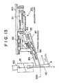
- FIG. 13 is a side view of a detecting/computing means for detecting the base position of a fibula head of FIG. 9
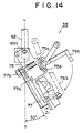
- FIG. 14 is a front view showing a schematic structure of the clamper of FIG. 9.
- FIG.1(A) shows a schematic constitution of a semi-automatic deboning process for a pig thigh.
- a semi-automatic pig thigh deboner of the present invention comprises: a preliminary processing apparatus 31 which includes stations constituting forward steps and a full automatic deboner 32 which includes stations constituting backward steps.
- a transport chain 33 of an endless type is provided, a work 30 which is the pig thigh is held by gripping, transport/processing means 34 is forced to take an inclined position by an inclining mechanism 37 at each of the stations through the transport chain 33, and cutting-in by hand and deboning with the help of an actuator 53 is performed, while in the full automatic deboner 32, driving means 70 provided for each station and the transport/processing means 34 which performs processing by receiving forces of stripping, rotating, vertical movement are connected with each other to perform a continuous automatic deboning operation.
- the preliminary processing apparatus 31 plays steps ST1 to ST7 (St i indicates the ith station counting from a starting station on the processing line) and specialized steps which are shown below are processed by operators 40 and inclining mechanisms 37 provided for the respective stations, wherein reduction in labor burden on the operators 40 and no requirements for a high degree of experience and special processing knowledge of the operators 40 are realized. That is, in the preliminary processing apparatus 31, the following 7 steps are included:
- steps ST8 to ST20 in which the work 30 which is fed from the preliminary processing apparatus 31, where deboning on a hip bone, and a sacrum and a caudal vertebrae has been completed, is continued to be transported on a transport line while being held by gripping by means of transfer/processing means 34 which is equipped with a clamper 35, driving forces of stripping of the meat section, rotating and vertical movement of the work is made to act on the work 30 by driving means 70 which is provided at each station which gets connected to the transport/processing means 34, thus the work 30 is rotated and vertically moved to strip the meat section from a bone section with the help of a meat separator 50 and an organic tissue is then cut by cutting means included in a cutter mechanism 55 separately provided to the full automatic deboner 32, whereby the work is completely deboned.
- a semi-automatic deboning process for a pig thigh comprises the preliminary processing steps of ST1 to ST7 and the full automatic processing steps of ST8 to ST20 to constitute a continuous circulating processing system; between both groups of the processing steps, a transport rails 33a of an endless type is provided, 20 transport/processing means 34 each of which has a transport mechanism equipped with the clamper 35 is hung from the endless transport chain 33 which runs on the rails 33a; the work is forced to take a downwardly inclined position with the help of an inclining mechanism 37 equipped in the preliminary processing apparatus; and the work receives driving forces of stripping of the meat section, rotating and vertical movement of the work by the driving means 70 equipped in each station of the full automatic deboner in the latter stage and at the same time the cutting means including through the cuter mechanism 55 makes possible automatic deboning processing such as stripping of the meat section, cutting an organic tissue and the like.
- the transport/processing means 34, a carriage 61, the clamper 35 (the former three items are necessary in the preliminary processing apparatus 31 as well), the meat separator 50, the cutter mechanism 55 and the detecting/computing means 90 for detecting the base position of the fibula head, which are necessary for the full automatic deboner 32, will be described in reference to FIGs. 9 to 14.
- the corresponding station Since rotations of the cuter and the work are required, as described later, for cutting an organic tissue including a meat section and cutting is performed after meat stripping of the meat section, the corresponding station, as shown in FIG. 9, comprises; a rotating mechanism 69 having functions synchronous rotation of a clamper 35 and a meat separator 50, stoppage at a home position and deceleration stoppage at a predetermined position; a vertical movement mechanism 67 of the clamper 35, a rotatable meat separator 50 and a cutter mechanism 55.
- Driving means 70 shown in FIG. 9 is provided in each station and a driving shaft 51 of the meat separator which is axially in common with a rotary vertically moving shaft 64 is designed to perfectly coincides with a stop position of a connecting shaft 62 of transport/processing means 34 hanging from a transport chain 33 through the carriage 60.
- the cutter mechanism 55 is designed to provide a horizontal rotary circular blade 56 so as to contact with the top side of the meat separator 50 in a squeezing position.
- the rotating mechanism 69 of the driving means 70 comprises: an upright rotary shaft 72 provided with a servo rotating mechanism 69a: two chain transfer mechanisms 65, 54 which have a synchronous speed of rotation are respectively equipped at the base section and the lower end of the rotary shaft 72; a home position driving control sensor 71a and a deceleration sensor for stoppage at a predetermined position 71b for the clamper 35 and the meat separator 50 equipped through the chain transfer mechanisms 65, 54; and a cutter retreat timing sensor 71c also equipped to constitutes a driving control sensor 71.
- the vertical movement mechanism 67 as shown in FIG. 9, comprises an upright rotary vertically moving shaft 64 having a straddle joint metal member 64a at the lower section, the mechanism 67 has a structure that it engages with a boat-shaped engaging member 63 in an engaging or disengaging manner, which, as described later, is mounted on the carriage 60, and the chain transfer mechanism 65 for rotation is disposed above the engaging member 63 and a rotary vertically moving shaft 64 connecting to a ball screw 68a driven by a servo motor 68 for vertical movement and a fixed vertically movement nut is provided on the chain transfer mechanism 65 so that the shaft 64 can vertically rotatably be moved with freedom.
- the transport/processing means 34 comprises: the clamper 35; a connecting shaft 62 supporting the clamper 35 in a freely inclined manner; and the carriage 60 constituting a transport mechanism, in a freely rotatable manner, mounted on the upper end of the connecting shaft 62.
- the clamper 35 has a body section 75 which is mounted so as to be freely inclined about a inclination pin 62a as a center at the lower section of the connecting shaft 62, a toggle lever 76d is provided on one side of the body 75, there is provided a reception opening 77 adjustable by a pin 77a and a adjusting pin 77b in a corresponding manner to a size of an ankle side section which is received on the other side of the body 75 and thereby the work is fixedly received so as to enable the work to be inclined at about 30 degrees.
- the carriage 60 as seen from FIG. 10(A), has 4 horizontally rotatable rollers 61a which are mounted at both ends of each of two parallel horizontal fixed shafts provided on both opposed sides of a near-rectangular member 61 through which the connection shaft 62 is freely rotatably inserted in an engaging manner and thereby a running plane on which the carriage 60 runs is limited, furthermore 4 upright rotary rollers 61a are provided at respective 4 corners of the bottom surface of the rectangular member 61 with the same interval of each pair so as to control its running in a direction rightward or left ward and thereby the carriage 60 is controlled in its running in two directions of rightward or leftward, and upward or downward so as to enable the carriage 60 to run along the transport rails 33a.
- a boat-shaped engaging member 63 with a top view of a near-rhombus is provided on the top of the upright connecting shaft 62 inserted in a freely rotatable manner in the center of the rectangular member 61 as shown in FIG. 1(B), the boat-shaped engaging member 63 engages with the straddle joint 64a mounted at the lower end of the rotary vertically moving shaft 64 when being stopped at a station and driving forces of vertical movement and rotating can be transferred to the transport/processing means 34 when the boat-shaped engaging member 63 is kept stopped.
- FIG. 11(A) a front view of the cutter mechanism 55 is shown
- FIG. 11(B) a side view thereof is shown.
- the cutter mechanism 55 comprises: a horizontal rotary circular blade 56; a drive motor 57 for the circular blade 56; an oscillation cylinder 59; a feed/retreat cylinder 58 for feeding the cutter to or retreating it from a cutting position; and a slide shifter 58a.
- a horizontal rotary circular blade 56, the feed/retreat cylinder 58 and the oscillation cylinder 59 which works so as to make the blade 56 freely contacted to a cutting section under a freely adjustable pressure are disposed at a lower section of a mounting member through the slide shifter 58a.
- the cutter mechanism 55 When the cutter mechanism 55 is used, not only is the horizontal rotary circular blade 56 which is driven by the drive motor 57 fed till contacting to a bone section through the cylinder 58 but the edge of the blade 56 is adjusted to press at a proper pressure by the oscillation cylinder 59. Then, the work 30 is rotated by a necessary cutting width. Thus, a combination of rotation of the work 30 and the cutter mechanism 55 constitutes cutting means and the work 30 can be cut by a necessary width from a desired position. If there is a projection and recess in a cutting section during rotation of the work 30, the oscillation cylinder 56 can absorb the projection and recess so as to realize perfect cutting.
- FIG. 12 a schematic structure 50 of the meat separator 50 is shown.
- an upright driving shaft 51a is freely rotatably mounted on a mounting base 51a and a ring 51c with a groove is provided between an upper fixed ring 51b and the base 51a of the driving shaft 51 so that the ring with a groove 51c can freely rotatably and vertically slide therebetween.
- the groove 51d of the ring 51c with a groove is supported by both sides of the groove 51d using a link 53b connecting to a driving fore end 53a of an actuator 53, the ring 51c with a groove is vertically moved by a link motion of the link 53b and the squeezing members 52, 52 each having a shape of three sides intersecting at right angles takes positions so as to squeeze therebetween while freely opening or closing, wherein a link mechanism is constructed from the top end of the ring 51c with a groove, two hinged supports 52a, 52a formed on the side of the upper fixed ring 51b and the squeezing member 52, 52.
- Upper squeezing plates 52b, 52b of the squeezing members 52 each are provided with a U-recess and when the squeezing members 52 are in a squeezing condition, a bone section of the work is stripped and scraped under a freely adjusted pressure so that the meat section can be separated from the bone section to a perfect manner.
- a squeezing plane of the meat separator 50 is located at a height at which the lower surface of the clamper 35 which is mounted to the connecting shaft 62 in an upright manner of the transport/processing means 34 with which the rotary vertically moving shaft 64 is in an engaging manner connected nearly contacts with the squeezing plane.
- a chain transfer mechanism 54 is provided between the lower end of the driving shaft 51 of the meat separator 50 and the upright rotary shaft 72 of the rotating mechanism 69 and the chain transfer mechanism 54 is operated in synchronization with a chain transfer mechanism 65 provided between the upright rotary shaft 72 and the rotary vertically moving shaft 64 and thereby cutting by the cutting means is improved to an more efficiently and more certain extent.
- a position of a femur head cannot be determined from the first reference value, a separate measurement is performed and a length between the base positions of the hind shank and the femur heads is measured and the value is set as a second reference value to determine the cutting positions in ST17 to ST19.
- FIG. 13 a schematic constitution of a detecting/computing means 90 for the base position of a fibula will be described below.
- a structure is present, in which a guide plate 83 and a measuring plate 87 which are parallel to each other and which are inclined with respect an axial line Y-Y of the connecting shaft 62 which moves vertically the clamper 35 for stripping the meat section of the fibula 45 are provided and the fore ends contact with the bone section 45 immediately after the squeezing plates 52b, 52b of the meat separator 50 pass by.
- the measuring plate 87 is disposed in an inclined manner with respect to the fibula 45 under a freely adjustable pressure by means of an auxiliary cylinder 84 through a linear guide 86 and a displacement of the measuring plate 87 relative to the guide plate 83 due to a change in shape of an exposed bone section to which the measuring plate 87 contacts is computed by an encoder 85 mounted to the auxiliary cylinder 84.
- the guide plate 83 is moved forward or backward by a forward/backward cylinder 81 mounted to a metal mounting member 80 through a linear guide 82.
- Measurement of the base position of a fibula head using the detecting/computing means 90 is performed in such a manner that the guide plate 83 and measuring plate 87 are moved forward by the forward/backward cylinder 81 so as to contact a bone section of the fibula with certainty under pressure, wherein the measuring plate 87 is also simultaneously moved by the auxiliary cylinder 84 so as to be positioned ahead of the guide plate 83.
- the clamper 35 is raised by a servo motor 68 for vertical movement, thereby a contact position of the fibula with the guide plate 83 and the measuring plate 87 is shifted downward and when the contact position reaches a point A of the lower end section of the fibula, the measuring plate 87 is rapidly moved forward relative to the guide plate 83.
- This change in condition is read by the encoder 85 to compute a joint position.
- Measurement of the base position of a femur head is performed in such a manner that the work is raised through the clamper using an air cylinder, not shown, wherein an encoder is provided for measuring a length of the raise, that is the femur is raised by the clamper 35 and a position where the head of the femur is caught by the meat separator and thereby the work is stopped is read and computed by the encoder to be set as the position of the minimal raise length.
- an operator processes a work 30, which is an hanging pig thigh, with the help of transport/processing means 34 in a standing position and at that time, the work 30 is positioned inclined at about 30 degrees downwardly so as to reduce a labor load.
- the full automatic deboner 32 works as can be seen from FIG. 5 in steps of ST8 to ST20 in such a manner that a work 30 is transported while being held by gripping by the transport/processing means 34 with the clamper 35 on the transport line, the work 30 is further rotated or vertically moved upward or downward by the driving means 70 provided at each station, thereby a meat section of the work 30 is stripped from a bone section thereof with the help of the meat separator 50 and then an organic tissue is cut by a cutter mechanism 55 separately equipped to debone automatically to a full extent. That is, the steps are advanced in the following ways:
- a pig thigh which is a heavy article is held in a hanging condition and transported through work stations, manual procedures can be limited only to cutting-in operations conducted in the preliminary steps, in which minor labor is consumed, and since the pig thigh to be processed in the preliminary steps is positioned inclined downwardly at about 30 degrees by the inclining capable clamper, a higher efficiency and a reduced labor operation can be achieved.
- Major deboning operations can be performed in a highly efficient processing by the full automatic machine, cutting by the cutter is conducted by a combination of the rotary blade and rotation of the work and thereby cutting position and cutting width are secured as necessary. Besides, detection of the base positions of respective fibula and femur heads is effected by a change in shape of a bone section and positional discrepancy due to individual differences is thereby prevented during the later stages to achieve a higher efficiency in operation and at the same time not only is conventional heavy labor excluded but hygienic deboning is realized.
Landscapes
- Life Sciences & Earth Sciences (AREA)
- Engineering & Computer Science (AREA)
- Wood Science & Technology (AREA)
- Zoology (AREA)
- Food Science & Technology (AREA)
- Processing Of Meat And Fish (AREA)
Description
Claims (10)
- A semi-automatic pig thigh deboner for sequentially deboning a pig thigh starting from a hind shank, comprising:wherein the workstations in the preliminary processing apparatus (31) comprise an inclining mechanism (37) holding the pig thigh, hanging down from the transporting/processing means (34), in a downwardly inclined position, for cutting-in for a hind shank and a femur by manual labour,a preliminary processing apparatus (31),an automatic processing apparatus (32),an endless transport line (32, 33, 33a) passing through the preliminary and automatic processing apparatus (31, 32) wherein a plurality of work stations are provided along the transport line in each processing apparatus (31, 32),transporting/processing means (34) for gripping the pig thigh and transporting it along the processing line sequentially through the workstations to subject it to respective processings,driving means (70) provided at each workstation for generating the driving forces for said processings,
wherein the driving means (70) of the workstations in the automatic processing apparatus (32) are adapted for generating the driving forces for stripping off meat and for rotational and vertical movement of the pig thigh, and the work stations of the automatic processing apparatus (32) further comprise:detecting/computing means (90) for detecting the base positions of heads of a fibula and a femur, andcutting means (50, 55) for automatically deboning the pig thigh by ripping the meat off and cutting organic tissue away from an exposed bone in cooperation with said driving means (34) of the stations of the automatic processing apparatus. - A pig thigh deboner according to claim 1, comprising a clamp rotation mechanism (69) to rotate a clamp (35) for gripping the pig thigh by a predetermined angle between the preceding and automatic processing apparatus (31, 32) and to rotate it back by said predetermined angle to recover the original rotation position after the automatic processing apparatus (32).
- A semi-automatic pig thigh deboner according to claim 1 or 2, wherein the transport/processing means (34) comprises: a clamper (35) to fixedly grip the ankle side section of a pig thigh; a connecting shaft (62) which can support the clamper in an inclining manner; and a transport mechanism (60, 61) through which the connecting shaft (62) is inserted in a freely rotatable manner, wherein the clamper (35) is rotated and vertically moved by receiving the driving forces from the driving means (70) which engages with the clamper by means of a boat-shaped engaging member (63), forming a transfer joint and provided on the top of the connecting shaft (62).
- A semi-automatic pig thigh deboner according to any of claims 1 to 3, wherein the driving means (70) comprises: a vertical moving mechanism (67) which vertically moves the pig thigh by being connected to the connecting shaft (62) of the transport/processing means (34,32); a rotating mechanism (69) to rotate the connecting shaft (62) and a meat section stripping mechanism (50) in synchronization with each other; and the meat section stripping mechanism (50).
- A semi-automatic pig thigh deboner according to claim 4, wherein the rotating mechanism (69) has confirmation functions of home position driving, deceleration stoppage at a predetermined position, and cutting stoppage.
- A semi-automatic pig thigh deboner according to claim 4 or 5, wherein the meat section stripping mechanism (50) is disposed on the same common axial line with the vertical movement mechanism, and a positioning section is located between both, one above the other while being held by both, and comprises: a squeezing section in which a bone section to be removed is squeezed under a freely adjustable pressure so as to perfectly strip the meat section from the bone section; and a driving shaft which can be rotatable at a synchronous speed of rotation with the clamper.
- A semi-automatic pig thigh deboner according to any of claims 1 to 6, wherein the cutting means (55) comprises a cutter mechanism (58, 59) which sets a cutter (56) under a freely adjustable pressure at a cutting start position, and a rotational angle of the work and a necessary cutting width can be set.
- A semi-automatic pig thigh deboner according to any of claims 1 to 7, wherein the detecting/computing means (90) for detecting the base positions of heads of a fibula and a femur comprises a position detecting/computing mechanism (83-87) to sense a rapid change in shape of the bone section.
- A semi-automatic pig thigh deboner according to any of claims 1 to 8, wherein the preliminary processing apparatus (31) comprises a hip bone, sacrum, caudal vertebrae removing mechanism (36) which removes the hip bone, sacrum and caudal vertebrae from the pig thigh having received cutting-in, whereby the apparatus performs removal of the hip bone, sacrum and caudal vertebrae and cutting-in before and after the removal of the bones.
- A semi-automatic pig thigh deboning process for sequentially deboning a pig thigh starting from a hind shank, while the pig thigh is transported along an endless transport line passing through a preliminary processing apparatus (31) and an automatic processing apparatus (32), wherein
the following steps are performed in the preliminary processing apparatus (31):and the following steps are automatically performed in the automatic processing apparatus (32) after the above steps:gripping the ankle side of the thigh by transporting/processing means (34) in a positioning section;removing a hip bone, and a sacrum and caudal vertebrae of the gripped thigh; andcutting-in for a hind shank and a femur while the thigh is held in a downwardly inclined position,stripping meat from around the hind shank;exposing a fibula and detecting the base position of a fibula head;stripping meat from around an upper part of a joint and cutting organic tissue exposed by the stripping, for separation of leg section muscles;cutting a patelliform bone related section;stripping for the femoral region and detecting the base position of a femur head;cutting a femur head related section; andcutting and separating the meat from the bone and letting it discharge.
Applications Claiming Priority (3)
| Application Number | Priority Date | Filing Date | Title |
|---|---|---|---|
| JP23655597A JP3603981B2 (en) | 1997-08-18 | 1997-08-18 | Pig thigh removal machine and pig thigh removal method |
| JP23655597 | 1997-08-18 | ||
| JP236555/97 | 1997-08-18 |
Publications (3)
| Publication Number | Publication Date |
|---|---|
| EP0898894A2 EP0898894A2 (en) | 1999-03-03 |
| EP0898894A3 EP0898894A3 (en) | 2000-07-12 |
| EP0898894B1 true EP0898894B1 (en) | 2003-05-14 |
Family
ID=17002392
Family Applications (1)
| Application Number | Title | Priority Date | Filing Date |
|---|---|---|---|
| EP98115553A Expired - Lifetime EP0898894B1 (en) | 1997-08-18 | 1998-08-18 | Semiautomatic pig thigt deboner and deboning process for pig thigh using same |
Country Status (6)
| Country | Link |
|---|---|
| US (1) | US6106384A (en) |
| EP (1) | EP0898894B1 (en) |
| JP (1) | JP3603981B2 (en) |
| DE (1) | DE69814540T2 (en) |
| DK (1) | DK0898894T3 (en) |
| ES (1) | ES2195242T3 (en) |
Cited By (1)
| Publication number | Priority date | Publication date | Assignee | Title |
|---|---|---|---|---|
| US12070040B2 (en) | 2020-08-31 | 2024-08-27 | Marel Meat B.V. | Method and system for deboning of a carcass leg part of a four-legged slaughter animal, for removing meat from a bone of the carcass leg part |
Families Citing this family (25)
| Publication number | Priority date | Publication date | Assignee | Title |
|---|---|---|---|---|
| NL1012703C2 (en) * | 1999-04-06 | 2000-10-09 | Stork Pmt | Method and device for processing a poultry leg. |
| JP3497476B2 (en) * | 2001-01-30 | 2004-02-16 | 株式会社前川製作所 | Method and apparatus for harvesting hollow carcasses |
| WO2004068953A1 (en) * | 2003-02-03 | 2004-08-19 | Mayekawa Mfg.Co., Ltd. | Boning system of meat |
| CN1842275A (en) * | 2003-08-27 | 2006-10-04 | 株式会社前川制作所 | Meat dressing/boning method and system therefor |
| WO2006080085A1 (en) * | 2005-01-25 | 2006-08-03 | Mayekawa Mfg.Co., Ltd. | Method of deboning animal meat block and deboning apparatus |
| EP1937077B1 (en) | 2005-09-06 | 2011-11-02 | Teknologisk Institut | Apparatus and method for cutting-free of tenderloin |
| WO2007053856A1 (en) * | 2005-11-04 | 2007-05-10 | Cargill, Incorporated | Meat tenderization methods and systems |
| NL1030388C2 (en) * | 2005-11-10 | 2007-05-16 | Systemate Group Bv | Boner. |
| US8070567B2 (en) * | 2006-10-17 | 2011-12-06 | Mayekawa Mfg. Co., Ltd. | Automatic deboning method and apparatus for deboning bone laden meat |
| WO2008096459A1 (en) * | 2007-02-06 | 2008-08-14 | Mayekawa Mfg. Co., Ltd. | Method and apparatus for deboning arm or leg part |
| FR2919473A1 (en) * | 2007-08-01 | 2009-02-06 | Durand Internat Soc Par Action | Carcass e.g. pig carcass, sawing method for carcass saw installation, involves maintaining front part of cutting edge of saw blade in active position when blade is displaced from upper outer position to lower outer portion |
| FR2921545A1 (en) * | 2007-09-28 | 2009-04-03 | Durand Internat Sa | DRIVING A SLIDING TOOL CARRIER OF A SLITTING MACHINE FOR SCREWING ANIMAL CARCASES |
| US7806753B2 (en) * | 2008-02-12 | 2010-10-05 | Stork Townsend Inc. | Skin-on ham deboning method |
| ES2985045T3 (en) * | 2009-12-17 | 2024-11-04 | Marel Red Meat B V | System and method for processing slaughtered animals and/or parts thereof |
| NL2003967C2 (en) * | 2009-12-17 | 2011-06-20 | Stork Townsend Bv | System and method for processing slaughtered animals and/or parts thereof. |
| JP5331244B2 (en) * | 2010-03-30 | 2013-10-30 | 株式会社前川製作所 | Method and apparatus for removing bone from thigh meat with bone |
| WO2012102609A1 (en) * | 2011-01-26 | 2012-08-02 | Foodmate B.V. | Method of deboning animal thighs for separating and collecting meat there from and apparatus for performing the method |
| FR2991851B1 (en) * | 2012-06-18 | 2014-06-20 | Adiv Dev | METHOD FOR BONING THE HAM AND HAM CONTAINMENT DEVICE AND SYSTEM FOR IMPLEMENTING THE METHOD AND AT LEAST ONE DEVICE |
| PL2869704T3 (en) * | 2012-07-04 | 2019-01-31 | Marel Meat B.V. | System for conveying carcasses or carcass parts of quadruped slaughter animals |
| JP7526030B2 (en) * | 2020-05-12 | 2024-07-31 | 株式会社前川製作所 | Crease System |
| JP7526031B2 (en) * | 2020-05-12 | 2024-07-31 | 株式会社前川製作所 | Workpiece measuring device and creasing system |
| NL2027156B1 (en) | 2020-12-18 | 2022-07-13 | Marel Meat Bv | A food processing system for processing carcass parts |
| JP7734639B2 (en) * | 2022-09-21 | 2025-09-05 | 株式会社前川製作所 | Bone-in meat clamping device, bone-in meat scoring device, and bone-in meat scoring method |
| JP7720489B2 (en) * | 2022-09-21 | 2025-08-07 | 株式会社前川製作所 | Bone-in meat clamping device |
| WO2025047152A1 (en) * | 2023-09-01 | 2025-03-06 | 株式会社前川製作所 | Workpiece gripping apparatus and workpiece gripping method |
Family Cites Families (9)
| Publication number | Priority date | Publication date | Assignee | Title |
|---|---|---|---|---|
| US2893051A (en) * | 1957-12-26 | 1959-07-07 | Robert T Massengill | Apparatus for preparing hams |
| US4843682A (en) * | 1986-12-05 | 1989-07-04 | Bowen David G | Poultry deboner |
| US5001812A (en) * | 1988-10-31 | 1991-03-26 | Hazenbroek Jacobus E | Revolving poultry thigh deboner |
| US5108344A (en) * | 1991-03-19 | 1992-04-28 | Mountain Meadows Lamb Corporation | Leg of lamb cut and method of boning same |
| FR2689373B1 (en) * | 1992-04-06 | 2000-07-13 | Device for restraining a piece of meat during boning. | |
| NL9300564A (en) * | 1992-09-29 | 1994-04-18 | Stork Protecon Bv | Method and device for deboning the legs of slaughtered animals. |
| DE4421882C2 (en) * | 1994-05-26 | 1997-02-06 | Nordischer Maschinenbau | Method and device for detaching meat from the bones of animal extremities |
| NL9400954A (en) * | 1994-06-13 | 1996-01-02 | Stork Protecon Langen Bv | Device for deboning meat pieces with a composite leg system. |
| NL1001226C2 (en) * | 1995-09-18 | 1997-03-20 | Stork Pmt | Method and device for deboning a leg. |
-
1997
- 1997-08-18 JP JP23655597A patent/JP3603981B2/en not_active Expired - Lifetime
-
1998
- 1998-08-17 US US09/135,013 patent/US6106384A/en not_active Expired - Fee Related
- 1998-08-18 DK DK98115553T patent/DK0898894T3/en active
- 1998-08-18 EP EP98115553A patent/EP0898894B1/en not_active Expired - Lifetime
- 1998-08-18 ES ES98115553T patent/ES2195242T3/en not_active Expired - Lifetime
- 1998-08-18 DE DE69814540T patent/DE69814540T2/en not_active Expired - Fee Related
Cited By (1)
| Publication number | Priority date | Publication date | Assignee | Title |
|---|---|---|---|---|
| US12070040B2 (en) | 2020-08-31 | 2024-08-27 | Marel Meat B.V. | Method and system for deboning of a carcass leg part of a four-legged slaughter animal, for removing meat from a bone of the carcass leg part |
Also Published As
| Publication number | Publication date |
|---|---|
| EP0898894A3 (en) | 2000-07-12 |
| US6106384A (en) | 2000-08-22 |
| DE69814540D1 (en) | 2003-06-18 |
| ES2195242T3 (en) | 2003-12-01 |
| JPH1156226A (en) | 1999-03-02 |
| EP0898894A2 (en) | 1999-03-03 |
| DK0898894T3 (en) | 2003-06-10 |
| DE69814540T2 (en) | 2004-03-18 |
| JP3603981B2 (en) | 2004-12-22 |
Similar Documents
| Publication | Publication Date | Title |
|---|---|---|
| US6106384A (en) | Semiautomatic pig deboner and deboning process for pig thigh using same | |
| JP5331244B2 (en) | Method and apparatus for removing bone from thigh meat with bone | |
| JP4961613B2 (en) | Method and device for deboning bone or thigh region, and program for executing cutting operation in device | |
| JP5057407B2 (en) | Deboning method and apparatus for livestock carcass for meat | |
| US5401210A (en) | Method of and apparatus for deboning meat | |
| JPWO2009139031A1 (en) | Mounting method and apparatus for meat with bone, and operation program for mounting | |
| EP2512255A2 (en) | System and method for processing slaughtered animals and/or parts thereof | |
| JP2002540776A (en) | Method and apparatus for processing poultry legs | |
| CN111096350B (en) | A device for removing legs from livestock carcasses | |
| JP4327099B2 (en) | Meat deboning equipment | |
| EP3537883B1 (en) | Method and device for processing carcasses of livestock along the spine | |
| JPH0748975B2 (en) | Poultry limb processing method | |
| JP4130266B2 (en) | Semi-automatic pig thigh deboning machine and its deboning method | |
| EP1266574A2 (en) | System of automatically loading parts of poultry carcasses to a plurality of apparatus | |
| EP0297114B1 (en) | Device for filleting of meat | |
| JP4555331B2 (en) | Meat block deboning method and deboning apparatus | |
| JP2001120165A (en) | Device for semi-automatically deboning pork hock/ shoulder butt and deboning system using the device | |
| EP1198178B1 (en) | Method and apparatus for aligning a dead fish | |
| JP4037282B2 (en) | Meat deboning method and meat deboning device | |
| JP4867050B2 (en) | Method and apparatus for creasing meat for livestock carcass and cutting operation program for creasing | |
| JP4908147B2 (en) | Method and apparatus for deboning boned meat | |
| TW202327457A (en) | Meat deposit removing device and meat deposit removing method | |
| EP3871507B1 (en) | Deboning apparatus for deboning a ham | |
| AU2018203246B2 (en) | Tunnel boning apparatus and method of tunnel boning | |
| WO2005053412A1 (en) | Method and device for detaching a bone part from a carcass part |
Legal Events
| Date | Code | Title | Description |
|---|---|---|---|
| PUAI | Public reference made under article 153(3) epc to a published international application that has entered the european phase |
Free format text: ORIGINAL CODE: 0009012 |
|
| AK | Designated contracting states |
Kind code of ref document: A2 Designated state(s): DE DK ES FR IT NL |
|
| AX | Request for extension of the european patent |
Free format text: AL;LT;LV;MK;RO;SI |
|
| PUAL | Search report despatched |
Free format text: ORIGINAL CODE: 0009013 |
|
| AK | Designated contracting states |
Kind code of ref document: A3 Designated state(s): AT BE CH CY DE DK ES FI FR GB GR IE IT LI LU MC NL PT SE |
|
| AX | Request for extension of the european patent |
Free format text: AL;LT;LV;MK;RO;SI |
|
| 17P | Request for examination filed |
Effective date: 20010104 |
|
| AKX | Designation fees paid |
Free format text: DE DK ES FR IT NL |
|
| 17Q | First examination report despatched |
Effective date: 20010913 |
|
| GRAH | Despatch of communication of intention to grant a patent |
Free format text: ORIGINAL CODE: EPIDOS IGRA |
|
| GRAH | Despatch of communication of intention to grant a patent |
Free format text: ORIGINAL CODE: EPIDOS IGRA |
|
| GRAA | (expected) grant |
Free format text: ORIGINAL CODE: 0009210 |
|
| AK | Designated contracting states |
Designated state(s): DE DK ES FR IT NL |
|
| REG | Reference to a national code |
Ref country code: DK Ref legal event code: T3 |
|
| REF | Corresponds to: |
Ref document number: 69814540 Country of ref document: DE Date of ref document: 20030618 Kind code of ref document: P |
|
| ET | Fr: translation filed | ||
| PLBE | No opposition filed within time limit |
Free format text: ORIGINAL CODE: 0009261 |
|
| STAA | Information on the status of an ep patent application or granted ep patent |
Free format text: STATUS: NO OPPOSITION FILED WITHIN TIME LIMIT |
|
| 26N | No opposition filed |
Effective date: 20040217 |
|
| PG25 | Lapsed in a contracting state [announced via postgrant information from national office to epo] |
Ref country code: IT Free format text: LAPSE BECAUSE OF NON-PAYMENT OF DUE FEES;WARNING: LAPSES OF ITALIAN PATENTS WITH EFFECTIVE DATE BEFORE 2007 MAY HAVE OCCURRED AT ANY TIME BEFORE 2007. THE CORRECT EFFECTIVE DATE MAY BE DIFFERENT FROM THE ONE RECORDED. Effective date: 20050818 |
|
| PGFP | Annual fee paid to national office [announced via postgrant information from national office to epo] |
Ref country code: ES Payment date: 20070809 Year of fee payment: 10 |
|
| PGFP | Annual fee paid to national office [announced via postgrant information from national office to epo] |
Ref country code: DK Payment date: 20070827 Year of fee payment: 10 |
|
| PGFP | Annual fee paid to national office [announced via postgrant information from national office to epo] |
Ref country code: NL Payment date: 20070831 Year of fee payment: 10 Ref country code: DE Payment date: 20071022 Year of fee payment: 10 |
|
| PGFP | Annual fee paid to national office [announced via postgrant information from national office to epo] |
Ref country code: FR Payment date: 20070810 Year of fee payment: 10 |
|
| REG | Reference to a national code |
Ref country code: DK Ref legal event code: EBP |
|
| NLV4 | Nl: lapsed or anulled due to non-payment of the annual fee |
Effective date: 20090301 |
|
| PG25 | Lapsed in a contracting state [announced via postgrant information from national office to epo] |
Ref country code: NL Free format text: LAPSE BECAUSE OF NON-PAYMENT OF DUE FEES Effective date: 20090301 |
|
| REG | Reference to a national code |
Ref country code: FR Ref legal event code: ST Effective date: 20090430 |
|
| PG25 | Lapsed in a contracting state [announced via postgrant information from national office to epo] |
Ref country code: DK Free format text: LAPSE BECAUSE OF NON-PAYMENT OF DUE FEES Effective date: 20080831 |
|
| PG25 | Lapsed in a contracting state [announced via postgrant information from national office to epo] |
Ref country code: FR Free format text: LAPSE BECAUSE OF NON-PAYMENT OF DUE FEES Effective date: 20080901 Ref country code: DE Free format text: LAPSE BECAUSE OF NON-PAYMENT OF DUE FEES Effective date: 20090303 |
|
| REG | Reference to a national code |
Ref country code: ES Ref legal event code: FD2A Effective date: 20080819 |
|
| PG25 | Lapsed in a contracting state [announced via postgrant information from national office to epo] |
Ref country code: ES Free format text: LAPSE BECAUSE OF NON-PAYMENT OF DUE FEES Effective date: 20080819 |
|
| PGFP | Annual fee paid to national office [announced via postgrant information from national office to epo] |
Ref country code: IT Payment date: 20070831 Year of fee payment: 10 |
|
| PGRI | Patent reinstated in contracting state [announced from national office to epo] |
Ref country code: IT Effective date: 20091201 |
|
| PGRI | Patent reinstated in contracting state [announced from national office to epo] |
Ref country code: IT Effective date: 20091201 |