EP0897555B1 - Film transport mechanism - Google Patents
Film transport mechanism Download PDFInfo
- Publication number
- EP0897555B1 EP0897555B1 EP97917961A EP97917961A EP0897555B1 EP 0897555 B1 EP0897555 B1 EP 0897555B1 EP 97917961 A EP97917961 A EP 97917961A EP 97917961 A EP97917961 A EP 97917961A EP 0897555 B1 EP0897555 B1 EP 0897555B1
- Authority
- EP
- European Patent Office
- Prior art keywords
- film
- rotor
- optical
- axis
- film support
- Prior art date
- Legal status (The legal status is an assumption and is not a legal conclusion. Google has not performed a legal analysis and makes no representation as to the accuracy of the status listed.)
- Expired - Lifetime
Links
- 230000007723 transport mechanism Effects 0.000 title description 5
- 239000010408 film Substances 0.000 claims description 113
- 230000003287 optical effect Effects 0.000 claims description 31
- 230000007246 mechanism Effects 0.000 claims description 13
- 239000012788 optical film Substances 0.000 claims description 13
- 238000011144 upstream manufacturing Methods 0.000 claims description 13
- 241000239290 Araneae Species 0.000 claims description 2
- 238000005096 rolling process Methods 0.000 description 10
- 230000000712 assembly Effects 0.000 description 1
- 238000000429 assembly Methods 0.000 description 1
- 238000001816 cooling Methods 0.000 description 1
- 239000000428 dust Substances 0.000 description 1
- 230000000694 effects Effects 0.000 description 1
- 238000012423 maintenance Methods 0.000 description 1
- 238000012986 modification Methods 0.000 description 1
- 230000004048 modification Effects 0.000 description 1
- 239000002245 particle Substances 0.000 description 1
Images


Classifications
-
- G—PHYSICS
- G03—PHOTOGRAPHY; CINEMATOGRAPHY; ANALOGOUS TECHNIQUES USING WAVES OTHER THAN OPTICAL WAVES; ELECTROGRAPHY; HOLOGRAPHY
- G03B—APPARATUS OR ARRANGEMENTS FOR TAKING PHOTOGRAPHS OR FOR PROJECTING OR VIEWING THEM; APPARATUS OR ARRANGEMENTS EMPLOYING ANALOGOUS TECHNIQUES USING WAVES OTHER THAN OPTICAL WAVES; ACCESSORIES THEREFOR
- G03B1/00—Film strip handling
- G03B1/18—Moving film strip by means which act on the film between the ends thereof
-
- G—PHYSICS
- G03—PHOTOGRAPHY; CINEMATOGRAPHY; ANALOGOUS TECHNIQUES USING WAVES OTHER THAN OPTICAL WAVES; ELECTROGRAPHY; HOLOGRAPHY
- G03B—APPARATUS OR ARRANGEMENTS FOR TAKING PHOTOGRAPHS OR FOR PROJECTING OR VIEWING THEM; APPARATUS OR ARRANGEMENTS EMPLOYING ANALOGOUS TECHNIQUES USING WAVES OTHER THAN OPTICAL WAVES; ACCESSORIES THEREFOR
- G03B1/00—Film strip handling
- G03B1/42—Guiding, framing, or constraining film in desired position relative to lens system
Definitions
- This invention relates generally to a mechanism for intermittently transporting film past a stationary point such as an aperture in a motion picture projector, camera or the like.
- a stationary point such as an aperture in a motion picture projector, camera or the like.
- film is to be interpreted broadly as including tape or other like elements.
- the invention has been devised primarily in the context of what are known as "rolling loop” motion picture projectors, although it is to be noted that the invention is not limited to mechanisms for use in optical projection or recording systems.
- U.S. Patent No. 3,494,524 to Jones discloses the principle of a rolling loop film transport mechanism. Briefly, the Jones mechanism includes a rotor having gaps and a curved stator for guiding the film between the rotor and the stator. As the rotor rotates, successive loops of film are formed in the rotor gaps, causing the film to move through one frame length each time the loop passes a stationary registration pin on the stator.
- Each loop is developed continuously in a rotor gap by a driven input sprocket as the gap travels from a film inlet location to a projection aperture.
- the loop then decays continuously as it travels from the aperture to a driven output sprocket.
- the registration pin is located adjacent the aperture for locating the film during projection.
- the rotor may have an overall diameter of about 40 inches (1016 millimeters) in the case of a projector for a 15 perforation 70 mm film format.
- the same considerations apply but the actual size varies.
- the projectors also take up significant floor space, i.e. require large projection rooms in theatres.
- the rotor of a rolling loop projector rotates in a horizontal plane (about a vertical axis) and sufficient space must be allowed for ancillary equipment such as film platters and other ancillary devices as well as for access to the projector by the operator and maintenance personnel.
- a projector normally includes a so-called "field flattener” lens element at the position of the aperture, on which successive frames of the film are laid for projection, as the film is advanced through the projector (see for example U.S. Patents Nos. 4,365,877 and 4,441,796 (Shaw)).
- the optical characteristics of the field flattener lens element are quite critical to proper projection.
- the face of the field flattener lens element on which the film is laid must have a precise shape.
- that face is defined by an arc centered on the rotational axis of the rotor, and the radius of the rotor is selected to match the curvature of the lens element face so as to maintain a uniform gap between the lens element and the rotor.
- An object of the present invention is to provide improvements in a rolling loop film transport mechanism which are aimed at permitting simplification, and in particular reduction in size and cost of the mechanism as a whole and/or permitting the use of a film support element having film support surface with a radius of curvature which is infinitely large.
- a mechanism for intermittently transporting film past a stationary optical film support element comprising a rotor rotatable about an axis and having a defined radius of curvature centred on said axis, stator means co-operating with the rotor to define a film passage and including said optical film support element having an optical axis, said element having a film support surface forming part of said film passage and extending about said optical axis, means upstream of said optical film support element for feeding film into said film passage at an input location; and, means for receiving film from said film passage at an output location downstream of said optical film support element; the rotor having gaps for receiving loops formed in film fed into said film passage and the rotor being rotatable about said axis to transport film through said film passage from said input location to said output location, so that successive portions of the film are laid onto and momentarily remain stationary on said film support surface of the optical film support element; characterised in that said film support surface has a radius of curvature
- upstream and downstream of course relate to the direction of film travel through the mechanism.
- the invention is based on the realization that it is in fact possible to significantly reduce the diameter of the rotor.
- the axis of rotation of the rotor is offset from the defined axis of the film support element in a direction towards the film input location by an amount sufficient to provide said predetermined minimum gap at the upstream side of the film support element which is adequate to maintain proper control of the film.
- conventional practice has been to maintain a uniform film gap across the entire face of the film support element.
- the present invention is based on the realization that this is not essential.
- the gap may be important that the gap not be allowed to become too large over the remainder of the lateral extent of the film support surface (i.e. towards the downstream end of the gap). It has been found that it may be desirable to contour the film support element or its housing beyond the normal upstream and/or downstream extent of the element, to curve back towards the rotor for maintaining a reasonable gap width.
- the practice is to maintain a gap between the film support element and the rotor which is a minimum sufficient to allow film to pass, including splices, and to ensure that this gap is uniform over the entire lateral extent of the film support element.
- this gap width is maintained at a point upstream of the optical centerline of the film support element assembly.
- the rotor may be reduced to approximately half its normal diameter, namely to 508 millimeters (20 inches) for a 15 perforation 70 mm format projector.
- the maximum gap width at the input end of the film support surface might be about twice the minimum gap and the maximum gap at the downstream end might be about six times the minimum gap.
- the projector is generally denoted by reference numeral 20 and includes a rotor 22 and fixed stator means generally indicated at 24 and including an input stator 26, an output stator 28.
- a field flattener lens element assembly 30 is located between the input stator and the output stator.
- the stators and the assembly 30 are is mounted on a fixed frame generally denoted 32, which also carries a projection lens assembly 34 associated with the field flattener assembly 30.
- the optical axis of the lens assembly 34 (and of the field flattener assembly 30) is indicated at B.
- stator means 24 co-operates with the rotor 22 to define a film passage which includes the field flattener lens element assembly 30.
- the film passage is generally indicated in Fig. 4 at P.
- Fig. 4 also shows one of the rotor gaps G receiving a loop L of film F.
- Fig. 1 shows an input sprocket assembly 36 at an input location.
- Fig. 1 also shows an output sprocket assembly 38 at an output location, for receiving film at the downstream end of the film passage P.
- the film is continuously fed into the film passage by the input sprocket assembly 36 as the rotor 22 rotates, so that loops L of film are formed in successive rotor gaps, in travelling towards the aperture of the projector, in Fig. 1 represented by the field flattener assembly 30. Successive portions of the film (corresponding to successive frames) are progressively laid flat onto the field flattener. The loops then progressively decay as the rotor rotates towards the output sprocket assembly 38, from where the film leaves the projector.
- a cam unit 40 is provided immediately upstream of the field flattener assembly 30 for decelerating successive portions of film as they approach the field flattener, again as described in the patents referred to previously.
- the projection lamp house is generally indicated by reference numeral 42 and is arranged to project light upwardly to a mirror 44 by which the light is projected forwardly along optical axis B through the film, the field flattener assembly 30 and the lens assembly 34. Cooling air for the lamp house is exhausted through a hose 46. Mounting the lamp below the rotor is also more efficient in terms of lamp operation.
- Rotor 22 is supported from above by a "spider" 48 (a frame with radiating arms) carried by a bearing 50 at the upper end of a vertical drive shaft (not shown).
- a single drive motor and a belt drive arrangement provides drive to the rotor 22, the input and output sprocket assemblies 36 and 38 respectively and the cam unit 40.
- Bearing 50 also incorporates a rotary air manifold for providing pressurized air at the locations on the rotor adjacent the gaps G for film cushioning purposes, as described in the '073 Shaw patent supra.
- An air inlet hose is shown at 52 and one of a number of air outlet hoses is indicated at 53.
- FIG. 3 the field flattener lens element assembly 30 is shown as seen from the "rotor side", i.e. looking towards the lens assembly 34.
- Assembly 30 includes a replaceable optical element known as a field flattener lens element, which is denoted 54.
- the field flattener has an optical surface 56 at its inner (film) side, on which successive portions of the film F are laid for projection as the film is transported past assembly 30.
- the arrow 58 in Fig. 3 represents light from the lamp house 42 that is being reflected off mirror 44 through the film for projection by lens assembly 34.
- the rotor is provided with shutters that cover the gaps G in the rotor, and hence the film loops L so that the light from the lamp house is intermittently obscured by the shutters between projection of successive frames as the gaps pass the field flattener assembly 30.
- Optical element 54 is mounted for vertical sliding movement in a housing 60 so that the element can be replaced and/or cleaned to remove dust, film particles and other debris that tends to accumulate on surface 56 during operation of the projector.
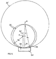
- Fig. 5 is a diagrammatic plan view showing the field flattener optical element 54 in association with the rotor 22.
- the optical axis of the projector is denoted B-B (to agree with Fig. 1) and the rotational axis of the rotor 22 is indicated at A.
- the large circle shown in ghost outline and denoted 22' indicates the diameter of a typical conventional rotor.
- the film support surface 56 of field flattener element 54 has a defined radius of curvature which is centered on the optical axis B. This radius is typically very large and may even be infinitely large (i.e. the surface 56 may be flat). In the preferred embodiment being described (15 perforation 70 mm format), the radius of curvature of surface 56 may be of the order of 508 mm (20 inches). In Fig. 5, that radius is denoted R F . In a typical rolling loop projector, the radius of the rotor is selected to be the same as the radius of curvature of the film support surface 56 so that the curvature of the rotor matches the curvature of surface 56 and a uniform gap can be maintained over the entire lateral extent of surface 56. In other words, the rotor would also have a radius of 508 mm (20 inches) . The spacing between the rotor and the field flattener element 54 would be selected to maintain a minimum gap sufficient to allow film to pass including splices.
- the radius of curvature of the rotor is selected to be significantly smaller than the radius of curvature of surface 56, for example in a range of from 1/4 to 3/4 of the radius of curvature of surface 56.
- the rotational axis A of the rotor is also offset from the optical axis B-B in a direction towards the film input location (input sprocket assembly 36) by an amount sufficient to provide a minimum film gap between the rotor and surface 56 at a point upstream of the optical axis B-B. As noted previously, it has been found that it is not necessary to maintain a uniform gap over the entire lateral extent of surface 56.
- the radius of curvature (R R ) of the rotor is reduced by half, i.e. to 254 mm (10 inches) and the rotor is offset by an amount indicated in Fig. 5 by the arrows denoted 62.
- the small circle 22 shown in ghost outline represents the position that the rotor would have occupied but for the offset.
- the offset is about 1/8 to 1/12 of the aperture width. For example, if the aperture width is 2-1/2 inches, the offset could be about 1/10 of that amount, about 0.25 inches.
- Fig. 2a shows the rotor size and offset as compared with a conventional rotor
- Fig. 2b illustrates the fact that the rotor can be mounted vertically for rotation about a horizontal axis.
- Fig. 4 also shows the rotor offset at 62.
- the minimum gap width is indicated by the arrow 66.
- the maximum width at the input side of the field flattener element is indicated at 68 and may be of the order of twice the minimum gap.
- the maximum gap width may be of the order of six times the minimum and occurs at the output end of element 54, as indicated at 70.
- the minimum gap (66) occurs approximately at a spacing from axis B-B equal to about twice the rotor offset (62). It is believed that the spacing preferably should be in a range of about 0.5 to 3 times the rotor offset.
- Fig. 4 also shows that the housing 60 for optical element 54 may be contoured to in effect further reduce the film gap to approximately the minimum gap at both the upstream and downstream end of the housing as indicated at 74 and 76 respectively.
- Housing 60 is not an optical element because it is outside the path of the projected image.
- suction means may be provided downstream of element 54 for drawing the film towards the surface of the holder. As best seen in Fig. 3, these suction means may comprise respective series 78 and 80 of suction ports located outwardly of the image area of the film, i.e. for drawing marginal areas of the film toward the holder.
- Reference numeral 82 indicates a suction hose communicating with the port 78 and 80. Hose 82 leads to a suction source 84 shown generally in Fig. 1.
Landscapes
- Physics & Mathematics (AREA)
- General Physics & Mathematics (AREA)
- Projection Apparatus (AREA)
- Registering, Tensioning, Guiding Webs, And Rollers Therefor (AREA)
Description
Claims (10)
- A mechanism for intermittently transporting film past a stationary optical film support element (54), the mechanism comprising:characterised in thata rotor (22) rotatable about an axis (A) and having a defined radius of curvature (RR) centred on said axis (A),stator means (24) co-operating with the rotor (22) to define a film passage (P) and including said optical film support element (54) having an optical axis (B-B), said element having a film support surface (56) forming part of said film passage (P) and extending about said optical axis (B-B),means (36) upstream of said optical film support element (54) for feeding film into said film passage (P) at an input location; and,means (38) for receiving film from said film passage (P) at an output location downstream of said optical film support element (54);the rotor (22) having gaps (G) for receiving loops (L) formed in film (F) fed into said film passage (P) and the rotor (22) being rotatable about said axis (A) to transport film through said film passage (P) from said input location to said output location, so that successive portions of the film are laid onto and momentarily remain stationary on said film support surface (56) of the optical film support element (54);
said film support surface (56) has a radius of curvature (RF) centered on said optical axis (B-B), said radius of curvature (RR) of the rotor (22) is significantly smaller than the radius of curvature (RF) of the film support surface (56), and said rotational axis (A) of the rotor (22) is offset from said optical axis (B) in a direction towards said film input location by an amount (62) sufficient to provide a predetermined minimum gap (66) between the rotor (22) and the film support surface (56) at a point upstream of said optical axis (B-B). - A camera, projector or like optical apparatus having a mechanism as claimed in claim 1, wherein said optical axis (B-B) coincides with the optical axis of the apparatus.
- An apparatus as claimed in claim 2, wherein the radius of curvature of the rotor (RR) is approximately one half of the radius of curvature (RF) of the film support surface (56) of the optical film support element (54).
- An apparatus as claimed in claim 2, wherein the radius of curvature (RF) of the film support surface (56) is infinitely large.
- An apparatus as claimed in claim 2, including an aperture having a defined width, wherein the rotor (22) is offset from said optical axis by a distance (62) in a range of about 1/8 to 1/12 of the aperture width.
- An apparatus as claimed in claim 2, wherein the rotor (22) is rotatable in a generally horizontal plane about a generally vertical axis (A), and wherein the apparatus further comprises rotor support means (50) comprising a spider (48) rotationally supported on said rotor axis (A) and disposed above the rotor (22) and supporting the same from above, and projection means including a projector lamp house (42) disposed below the rotor (22) and arranged to project light upwardly for reflection through said film (F).
- An apparatus as claimed in claim 2, wherein said minimum gap (66) is located at a position spaced from said optical axis (B-B) by an amount approximately equal to 0.5 to 3 times the rotor offset (62).
- An apparatus as claimed in claim 2, wherein said stationary optical film support element (54) is located in a housing (60), and wherein said housing (60) is contoured to reduce the width of the film passage (P) to approximate said minimum gap (66) upstream and downstream of said optical film support element (54).
- An apparatus as claimed in claim 8, further comprising suction means (78,80) in said housing (60) for drawing film towards said extension downstream of the element (54).
- An apparatus as claimed in claim 2, wherein the rotor (22) is rotatable in a generally vertical plane about a generally horizontal axis.
Applications Claiming Priority (3)
| Application Number | Priority Date | Filing Date | Title |
|---|---|---|---|
| US646581 | 1996-05-08 | ||
| US08/646,581 US5587750A (en) | 1996-05-08 | 1996-05-08 | Film transport mechanism |
| PCT/CA1997/000308 WO1997042544A1 (en) | 1996-05-08 | 1997-05-06 | Film transport mechanism |
Publications (2)
| Publication Number | Publication Date |
|---|---|
| EP0897555A1 EP0897555A1 (en) | 1999-02-24 |
| EP0897555B1 true EP0897555B1 (en) | 2003-08-06 |
Family
ID=24593604
Family Applications (1)
| Application Number | Title | Priority Date | Filing Date |
|---|---|---|---|
| EP97917961A Expired - Lifetime EP0897555B1 (en) | 1996-05-08 | 1997-05-06 | Film transport mechanism |
Country Status (8)
| Country | Link |
|---|---|
| US (1) | US5587750A (en) |
| EP (1) | EP0897555B1 (en) |
| JP (1) | JP3453147B2 (en) |
| CN (1) | CN1122871C (en) |
| AU (1) | AU2629097A (en) |
| CA (1) | CA2253596C (en) |
| DE (1) | DE69723974T2 (en) |
| WO (1) | WO1997042544A1 (en) |
Families Citing this family (5)
| Publication number | Priority date | Publication date | Assignee | Title |
|---|---|---|---|---|
| US6120151A (en) * | 1998-11-17 | 2000-09-19 | Advanced Image Systems, Inc. | System and method for transporting film and motion picture projector utilizing same |
| CA2267674C (en) * | 1999-03-31 | 2010-03-30 | Imax Corporation | Method for cooling an arc lamp |
| US6257725B1 (en) * | 1999-07-09 | 2001-07-10 | Advanced Image Systems, Inc. | Shutter assembly for a motion film projection |
| US8147065B2 (en) * | 2004-04-20 | 2012-04-03 | Imax Corporation | Electronically controlled film transport methods and systems |
| CN111856861B (en) * | 2019-04-28 | 2022-04-26 | 宁波舜宇车载光学技术有限公司 | Dynamic projection system and dynamic projection method |
Family Cites Families (9)
| Publication number | Priority date | Publication date | Assignee | Title |
|---|---|---|---|---|
| US3494524A (en) * | 1966-04-18 | 1970-02-10 | Peter Ronald Wright Jones | Rolling loop film-transport mechanism |
| US3600073A (en) * | 1969-11-24 | 1971-08-17 | Multiscreen Corp Ltd | Rolling loop film transport mechanism |
| US3794415A (en) * | 1972-07-13 | 1974-02-26 | Multiscreen Corp Ltd | Rolling loop transport mechanism |
| CA1065358A (en) * | 1976-04-02 | 1979-10-30 | William C. Shaw | Inlet guide structure for rolling loop film transport mechanism |
| US4039256A (en) * | 1976-05-24 | 1977-08-02 | Ampex Corporation | Intermittent film transport registration stabilization device |
| US4053230A (en) * | 1976-09-13 | 1977-10-11 | Balousek Ronald R | Full-width film-supporting, driving, and stripping arrangement for motion picture film printing machines |
| US4180194A (en) | 1977-12-30 | 1979-12-25 | Cambridge Consultants Of Bar Hill | Web transport mechanism and method |
| US4365877A (en) * | 1981-08-06 | 1982-12-28 | Imax Systems Corporation | Field flattener lens element assembly |
| US4441796A (en) * | 1981-08-06 | 1984-04-10 | Imax Systems Corporation | Film support element assembly |
-
1996
- 1996-05-08 US US08/646,581 patent/US5587750A/en not_active Expired - Lifetime
-
1997
- 1997-05-06 WO PCT/CA1997/000308 patent/WO1997042544A1/en not_active Ceased
- 1997-05-06 JP JP53937297A patent/JP3453147B2/en not_active Expired - Fee Related
- 1997-05-06 EP EP97917961A patent/EP0897555B1/en not_active Expired - Lifetime
- 1997-05-06 DE DE69723974T patent/DE69723974T2/en not_active Expired - Lifetime
- 1997-05-06 CN CN97195583A patent/CN1122871C/en not_active Expired - Fee Related
- 1997-05-06 CA CA002253596A patent/CA2253596C/en not_active Expired - Fee Related
- 1997-05-06 AU AU26290/97A patent/AU2629097A/en not_active Abandoned
Also Published As
| Publication number | Publication date |
|---|---|
| EP0897555A1 (en) | 1999-02-24 |
| DE69723974T2 (en) | 2004-07-22 |
| JP3453147B2 (en) | 2003-10-06 |
| CN1122871C (en) | 2003-10-01 |
| US5587750A (en) | 1996-12-24 |
| AU2629097A (en) | 1997-11-26 |
| DE69723974D1 (en) | 2003-09-11 |
| CA2253596C (en) | 2003-03-18 |
| CA2253596A1 (en) | 1997-11-13 |
| JP2000509517A (en) | 2000-07-25 |
| WO1997042544A1 (en) | 1997-11-13 |
| CN1222235A (en) | 1999-07-07 |
Similar Documents
| Publication | Publication Date | Title |
|---|---|---|
| US4971435A (en) | 3-D motion picture projection apparatus | |
| US4966454A (en) | 3-D motion picture projector | |
| US5587750A (en) | Film transport mechanism | |
| EP1002257B1 (en) | Switchable format film projection system | |
| JPH06208176A (en) | Bow shaped gate for photographic-film scanner | |
| US6120151A (en) | System and method for transporting film and motion picture projector utilizing same | |
| RU2207610C2 (en) | Switchable film-movement projection system | |
| HK1020377A (en) | Film transport mechanism | |
| US4978215A (en) | Image projecting system | |
| JPH0656421B2 (en) | Blower mechanism used for image forming apparatus | |
| US20030048419A1 (en) | Switchable format film projection system | |
| US6257725B1 (en) | Shutter assembly for a motion film projection | |
| US5010362A (en) | Image projecting system | |
| US5581313A (en) | Reversing film projection system | |
| JPS6333131B2 (en) | ||
| Solow et al. | An automatic 35mm A&B composite color printer | |
| JPH0245174B2 (en) | ||
| JPH09236872A (en) | Band-shaped film support device and band-shaped film running device | |
| JPH09230502A (en) | Band-shaped film support device and band-shaped film running device | |
| JPH11237693A (en) | Photo printing equipment | |
| JPS62249174A (en) | Fan device for copying machine | |
| JPH05181205A (en) | Automatic printing and developing device for 3D stereoscopic pictures and normal pictures |
Legal Events
| Date | Code | Title | Description |
|---|---|---|---|
| PUAI | Public reference made under article 153(3) epc to a published international application that has entered the european phase |
Free format text: ORIGINAL CODE: 0009012 |
|
| 17P | Request for examination filed |
Effective date: 19981123 |
|
| AK | Designated contracting states |
Kind code of ref document: A1 Designated state(s): DE FR GB IT |
|
| 17Q | First examination report despatched |
Effective date: 20000809 |
|
| GRAG | Despatch of communication of intention to grant |
Free format text: ORIGINAL CODE: EPIDOS AGRA |
|
| GRAG | Despatch of communication of intention to grant |
Free format text: ORIGINAL CODE: EPIDOS AGRA |
|
| GRAG | Despatch of communication of intention to grant |
Free format text: ORIGINAL CODE: EPIDOS AGRA |
|
| GRAH | Despatch of communication of intention to grant a patent |
Free format text: ORIGINAL CODE: EPIDOS IGRA |
|
| GRAH | Despatch of communication of intention to grant a patent |
Free format text: ORIGINAL CODE: EPIDOS IGRA |
|
| GRAA | (expected) grant |
Free format text: ORIGINAL CODE: 0009210 |
|
| AK | Designated contracting states |
Designated state(s): DE FR GB IT |
|
| REG | Reference to a national code |
Ref country code: GB Ref legal event code: FG4D |
|
| REF | Corresponds to: |
Ref document number: 69723974 Country of ref document: DE Date of ref document: 20030911 Kind code of ref document: P |
|
| ET | Fr: translation filed | ||
| PLBE | No opposition filed within time limit |
Free format text: ORIGINAL CODE: 0009261 |
|
| STAA | Information on the status of an ep patent application or granted ep patent |
Free format text: STATUS: NO OPPOSITION FILED WITHIN TIME LIMIT |
|
| 26N | No opposition filed |
Effective date: 20040507 |
|
| PGFP | Annual fee paid to national office [announced via postgrant information from national office to epo] |
Ref country code: FR Payment date: 20110607 Year of fee payment: 15 |
|
| PGFP | Annual fee paid to national office [announced via postgrant information from national office to epo] |
Ref country code: GB Payment date: 20110519 Year of fee payment: 15 |
|
| PGFP | Annual fee paid to national office [announced via postgrant information from national office to epo] |
Ref country code: IT Payment date: 20110530 Year of fee payment: 15 Ref country code: DE Payment date: 20110523 Year of fee payment: 15 |
|
| GBPC | Gb: european patent ceased through non-payment of renewal fee |
Effective date: 20120506 |
|
| PG25 | Lapsed in a contracting state [announced via postgrant information from national office to epo] |
Ref country code: IT Free format text: LAPSE BECAUSE OF NON-PAYMENT OF DUE FEES Effective date: 20120506 |
|
| REG | Reference to a national code |
Ref country code: FR Ref legal event code: ST Effective date: 20130131 |
|
| REG | Reference to a national code |
Ref country code: DE Ref legal event code: R119 Ref document number: 69723974 Country of ref document: DE Effective date: 20121201 |
|
| PG25 | Lapsed in a contracting state [announced via postgrant information from national office to epo] |
Ref country code: FR Free format text: LAPSE BECAUSE OF NON-PAYMENT OF DUE FEES Effective date: 20120531 Ref country code: GB Free format text: LAPSE BECAUSE OF NON-PAYMENT OF DUE FEES Effective date: 20120506 |
|
| PG25 | Lapsed in a contracting state [announced via postgrant information from national office to epo] |
Ref country code: DE Free format text: LAPSE BECAUSE OF NON-PAYMENT OF DUE FEES Effective date: 20121201 |