EP0897489B1 - Pneumatic spring - Google Patents
Pneumatic spring Download PDFInfo
- Publication number
- EP0897489B1 EP0897489B1 EP97922875A EP97922875A EP0897489B1 EP 0897489 B1 EP0897489 B1 EP 0897489B1 EP 97922875 A EP97922875 A EP 97922875A EP 97922875 A EP97922875 A EP 97922875A EP 0897489 B1 EP0897489 B1 EP 0897489B1
- Authority
- EP
- European Patent Office
- Prior art keywords
- air spring
- bush
- rod
- spring according
- pot
- Prior art date
- Legal status (The legal status is an assumption and is not a legal conclusion. Google has not performed a legal analysis and makes no representation as to the accuracy of the status listed.)
- Expired - Lifetime
Links
- 229920001971 elastomer Polymers 0.000 claims abstract description 6
- 239000000806 elastomer Substances 0.000 claims abstract description 5
- 238000005096 rolling process Methods 0.000 claims abstract description 4
- 239000000463 material Substances 0.000 claims abstract description 3
- 230000003014 reinforcing effect Effects 0.000 claims abstract description 3
- 229920001967 Metal rubber Polymers 0.000 claims description 4
- 239000002131 composite material Substances 0.000 claims description 4
- 229910052782 aluminium Inorganic materials 0.000 claims description 3
- XAGFODPZIPBFFR-UHFFFAOYSA-N aluminium Chemical compound [Al] XAGFODPZIPBFFR-UHFFFAOYSA-N 0.000 claims description 3
- 239000004033 plastic Substances 0.000 claims description 3
- -1 polytetrafluorethylene Polymers 0.000 claims description 2
- 229920001343 polytetrafluoroethylene Polymers 0.000 claims description 2
- 239000004411 aluminium Substances 0.000 claims 1
- 239000004020 conductor Substances 0.000 claims 1
- 229910052751 metal Inorganic materials 0.000 claims 1
- 239000002184 metal Substances 0.000 claims 1
- 239000013536 elastomeric material Substances 0.000 description 2
- 238000001816 cooling Methods 0.000 description 1
- 229920000642 polymer Polymers 0.000 description 1
- 239000004810 polytetrafluoroethylene Substances 0.000 description 1
- 239000006228 supernatant Substances 0.000 description 1
- 239000000725 suspension Substances 0.000 description 1
- 239000013585 weight reducing agent Substances 0.000 description 1
- 238000003466 welding Methods 0.000 description 1
Images

Classifications
-
- F—MECHANICAL ENGINEERING; LIGHTING; HEATING; WEAPONS; BLASTING
- F16—ENGINEERING ELEMENTS AND UNITS; GENERAL MEASURES FOR PRODUCING AND MAINTAINING EFFECTIVE FUNCTIONING OF MACHINES OR INSTALLATIONS; THERMAL INSULATION IN GENERAL
- F16C—SHAFTS; FLEXIBLE SHAFTS; ELEMENTS OR CRANKSHAFT MECHANISMS; ROTARY BODIES OTHER THAN GEARING ELEMENTS; BEARINGS
- F16C23/00—Bearings for exclusively rotary movement adjustable for aligning or positioning
- F16C23/02—Sliding-contact bearings
- F16C23/04—Sliding-contact bearings self-adjusting
- F16C23/043—Sliding-contact bearings self-adjusting with spherical surfaces, e.g. spherical plain bearings
- F16C23/045—Sliding-contact bearings self-adjusting with spherical surfaces, e.g. spherical plain bearings for radial load mainly, e.g. radial spherical plain bearings
-
- F—MECHANICAL ENGINEERING; LIGHTING; HEATING; WEAPONS; BLASTING
- F16—ENGINEERING ELEMENTS AND UNITS; GENERAL MEASURES FOR PRODUCING AND MAINTAINING EFFECTIVE FUNCTIONING OF MACHINES OR INSTALLATIONS; THERMAL INSULATION IN GENERAL
- F16F—SPRINGS; SHOCK-ABSORBERS; MEANS FOR DAMPING VIBRATION
- F16F13/00—Units comprising springs of the non-fluid type as well as vibration-dampers, shock-absorbers, or fluid springs
- F16F13/02—Units comprising springs of the non-fluid type as well as vibration-dampers, shock-absorbers, or fluid springs damping by frictional contact between the spring and braking means
-
- F—MECHANICAL ENGINEERING; LIGHTING; HEATING; WEAPONS; BLASTING
- F16—ENGINEERING ELEMENTS AND UNITS; GENERAL MEASURES FOR PRODUCING AND MAINTAINING EFFECTIVE FUNCTIONING OF MACHINES OR INSTALLATIONS; THERMAL INSULATION IN GENERAL
- F16F—SPRINGS; SHOCK-ABSORBERS; MEANS FOR DAMPING VIBRATION
- F16F9/00—Springs, vibration-dampers, shock-absorbers, or similarly-constructed movement-dampers using a fluid or the equivalent as damping medium
- F16F9/02—Springs, vibration-dampers, shock-absorbers, or similarly-constructed movement-dampers using a fluid or the equivalent as damping medium using gas only or vacuum
- F16F9/04—Springs, vibration-dampers, shock-absorbers, or similarly-constructed movement-dampers using a fluid or the equivalent as damping medium using gas only or vacuum in a chamber with a flexible wall
- F16F9/05—Springs, vibration-dampers, shock-absorbers, or similarly-constructed movement-dampers using a fluid or the equivalent as damping medium using gas only or vacuum in a chamber with a flexible wall the flexible wall being of the rolling diaphragm type
-
- B—PERFORMING OPERATIONS; TRANSPORTING
- B60—VEHICLES IN GENERAL
- B60G—VEHICLE SUSPENSION ARRANGEMENTS
- B60G2202/00—Indexing codes relating to the type of spring, damper or actuator
- B60G2202/30—Spring/Damper and/or actuator Units
- B60G2202/31—Spring/Damper and/or actuator Units with the spring arranged around the damper, e.g. MacPherson strut
- B60G2202/314—The spring being a pneumatic spring
-
- B—PERFORMING OPERATIONS; TRANSPORTING
- B60—VEHICLES IN GENERAL
- B60G—VEHICLE SUSPENSION ARRANGEMENTS
- B60G2204/00—Indexing codes related to suspensions per se or to auxiliary parts
- B60G2204/40—Auxiliary suspension parts; Adjustment of suspensions
- B60G2204/416—Ball or spherical joints
Definitions
- the invention relates to an air spring, in particular for rail vehicles, commercial vehicles and Busses, comprising a bellows made of elastomeric material, optionally with Reinforcing inserts is provided; a pot, on the upper part of which the bellows is attached, the bellows preferably rolling along the outer wall of the pot; one at a distance plate-shaped lid arranged to the pot, to which the other end of the bellows is attached is; a centrally located rod, which is firmly connected to the lid and thereby in particular protrudes from the cover in a protrusion, the rod also being connected to the Submerge the bellows parallel to the pot; a ball joint that is between the pot and the rod is in contact with the inner wall of the pot; as well as an air duct (DE-A-38 28 203, EP-A-0 554 573).
- the intermediate bush, slide bush and the ball joint run cylindrical around the rod.
- the rod also called the guide shaft
- the rod thus forms the core of the overall system.
- the slide bush and the intermediate bush are preferably each formed in one piece.
- the Slide bushing with a minimum wall thickness of 0.1 mm consists of a sliding Plastic, especially made of polytetrafluoroethylene.
- the Slide bushing has an oblique and continuous slot in the axial direction.
- a thermally compatible material, in particular aluminum used. With the use of aluminum there is also a significant weight reduction connected.
- the intermediate bush has a recess on its inner wall has, in which the sliding bush sits with about half the wall thickness.
- the outer surface of the Intermediate bushing is also provided with a recess in which the ball joint with its Inside part sits.
- the intermediate bush (5) on its inner wall has a recess (23; Fig. 2), in who sits the sliding bush with about half the wall thickness and while sliding on the The outer wall of the tubular rod (A) is in contact. Furthermore, the intermediate bush (5) is on its outer wall also provided with a recess (24; Fig. 2) in which the ball joint (7) as three-layer metal-elastomer composite with its inner part. In order to secure the Ball joint (7) and the intermediate bush (5) are two towards the lower air spring part Circlips (9, 18) are present, the circlip (18) in a notch that is located inside the outer wall of the intermediate bush.
- the tube rod (A) includes as an air duct (19) at least one opening that the rod interior (21) with the Air spring chamber (22) connects.
- the pipe rod (A) is in the area (C) of the sliding bush (6) conical, namely by increasing the diameter of the Rod interior (21).
- Fig. 2 shows an air duct (20) inside the intermediate bush (5) in the axial direction (X; Fig. 1) is arranged and is in communication with the air spring space.
- the air duct here consists of several outer grooves, which are at substantially the same intervals over the the entire circumference of the intermediate bushing (5) is distributed.
- the intermediate socket is on their inner and outer wall with recesses (23, 24), the meaning in Connection with the description of the figures 1 has already been set out.
Landscapes
- Engineering & Computer Science (AREA)
- General Engineering & Computer Science (AREA)
- Mechanical Engineering (AREA)
- Fluid-Damping Devices (AREA)
- Vehicle Body Suspensions (AREA)
- Body Structure For Vehicles (AREA)
- Diaphragms And Bellows (AREA)
- Support Of The Bearing (AREA)
- Springs (AREA)
Abstract
Description
Die Erfindung betrifft eine Luftfeder, insbesondere für Schienenfahrzeuge, Nutzfahrzeuge und Busse, umfassend einen Balg aus elastomerem Werkstoff, der gegebenenfalls mit Verstärkungseinlagen versehen ist; einen Topf, an dessem oberen Teil der Balg befestigt ist, wobei der Balg vorzugsweise an der Außenwand des Topfes entlang abrollt; einen in Abstand zum Topf angeordneten plattenförmigen Deckel, an dem das andere Ende des Balges befestigt ist; eine mittig angeordnete Stange, die mit dem Deckel fest verbunden ist und dabei insbesondere in einem Überstand aus dem Deckel herausragt, wobei ferner die Stange zu dem Balg parallel verlaufend in den Topf eintaucht; ein Kugelgelenk, das sich zwischen dem Topf und der Stange befindet und dabei an der Innenwand des Topfes anliegt; sowie eine Luftführung (DE-A-38 28 203, EP-A- 0 554 573).The invention relates to an air spring, in particular for rail vehicles, commercial vehicles and Busses, comprising a bellows made of elastomeric material, optionally with Reinforcing inserts is provided; a pot, on the upper part of which the bellows is attached, the bellows preferably rolling along the outer wall of the pot; one at a distance plate-shaped lid arranged to the pot, to which the other end of the bellows is attached is; a centrally located rod, which is firmly connected to the lid and thereby in particular protrudes from the cover in a protrusion, the rod also being connected to the Submerge the bellows parallel to the pot; a ball joint that is between the pot and the rod is in contact with the inner wall of the pot; as well as an air duct (DE-A-38 28 203, EP-A-0 554 573).
In modernen Schienenfahrzeugen beispielsweise werden häufig luftfedern als Sekundärfedersystem eingesetzt. Dieses Sekundärfedersystem soll nun horizontale Kräfte bis 20 KN statisch an das Drehgestell leiten können, und zwar vom Wagenkasten. Dabei sind Winkelauslenkungen bis 7° möglich. Ferner werden bei geringen Bauhöhen und bei einem geringen Gewicht große vertikale Verfahrwege gefordert.In modern rail vehicles, for example, air springs are often used as Secondary spring system used. This secondary spring system is now supposed to have horizontal forces up to 20 KN statically to the bogie, from the car body. Are there Angular deflections up to 7 ° possible. Furthermore, with low overall heights and one low weight requires large vertical travels.
Zwecks Lösung dieser Aufgabe wird nun erfindungsgemäß eine gattungsgemäße Luftfeder vorgeschlagen, die gemäß Kennzeichen des Patentanspruches 1 kombinativ folgende zusätzliche Teile umfaßt:
- eine Gleitbuchse, die zwischen dem Kugelgelenk und der Stange angeordnet ist und dabei gleitend an der Außenwand der Stange anliegt; sowie
- eine Zwischenbuchse, die zwischen dem Kugelgelenk und der Gleitbuchse vorhanden ist.
- a slide bush which is arranged between the ball joint and the rod and thereby slidably abuts the outer wall of the rod; such as
- an intermediate bush which is present between the ball joint and the sliding bush.
Die Zwischenbuchse, Gleitbuchse und das Kugelgelenk umlaufen dabei die Stange zylindrisch. Die Stange (auch Führungswelle genannt) bildet also den Kern des Gesamtsystemes. The intermediate bush, slide bush and the ball joint run cylindrical around the rod. The rod (also called the guide shaft) thus forms the core of the overall system.
Die Gleitbuchse und die Zwischenbuchse sind vorzugsweise jeweils einstückig ausgebildet. Die Gleitbuchse mit einer Mindestwandstärke von 0,1 mm besteht dabei aus einem gleiffähigen Kunststoff, insbesondere aus Polytetrafluorethylen. Zwecks besserer Montage weist die Gleitbuchse in Achsrichtung einen schräg und durchgehend verlaufenden Schlitz auf. Was die Zwischenbuchse betrifft, so wird ein wärmeleiffähiger Werkstoff, insbesondere Aluminium, verwendet. Mit der Verwendung von Aluminium ist auch eine erhebliche Gewichtsreduzierung verbunden.The slide bush and the intermediate bush are preferably each formed in one piece. The Slide bushing with a minimum wall thickness of 0.1 mm consists of a sliding Plastic, especially made of polytetrafluoroethylene. For better assembly, the Slide bushing has an oblique and continuous slot in the axial direction. What the Intermediate bushing is concerned, a thermally compatible material, in particular aluminum, used. With the use of aluminum there is also a significant weight reduction connected.
Ferner ist es zweckmäßig, wenn die Zwischenbuchse an ihrer Innenwand eine Aussparung aufweist, in der die Gleitbuchse mit etwa der halben Wandstärke einsitzt. Die Außenfläche der Zwischenbuchse ist ebenfalls mit einer Aussparung versehen, in der das Kugelgelenk mit seinem Innenteil einsitzt.It is also expedient if the intermediate bush has a recess on its inner wall has, in which the sliding bush sits with about half the wall thickness. The outer surface of the Intermediate bushing is also provided with a recess in which the ball joint with its Inside part sits.
Hinsichtlich der Luftführung kommen zweckmäßigerweise folgende Varianten zur Anwendung:
- Die Rohrstange ist mit wenigstens einer Öffnung versehen, die den in Achsrichtung durchgehend verlaufenden Stangeninnenraum mit dem Luftfederraum verbindet.
- Innerhalb der Zwischenbuchse ist in Achsrichtung wenigstens einle durchgehend verlaufende/r Kanal oder Außennut angeordnet, der/die mit dem Luftfederraum in Verbindung steht. Vorteilhafterweise sind dabei mehrere Kanäle oder Außennuten vorhanden, die im wesentlichen in gleichen Abständen über den gesamten Umfang der Zwischenbuchse verteilt vorhanden sind. Auf diese Weise wird zusätzlich für eine Luftkühlung gesorgt.
- The tubular rod is provided with at least one opening which connects the rod interior extending continuously in the axial direction to the air spring chamber.
- At least one continuous channel or external groove, which is connected to the air spring chamber, is arranged within the intermediate bush in the axial direction. Advantageously, there are a plurality of channels or external grooves which are distributed essentially at equal intervals over the entire circumference of the intermediate bush. In this way, additional air cooling is provided.
Auch die Kombination beider Luftführungsvarianten ist möglich.The combination of both air routing variants is also possible.
Weitere zweckmäßige Ausgestaltungen der erfindungsgemäßen Luftfeder sind:
- Die Innenwand der Rohrstange ist im Bereich der Gleitbuchse konisch ausgebildet, und zwar unter Vergrößerung des Durchmessers des Stangeninnenraumes, was zu einer Gewichtseinspraung führt. Auch eine Optimierung der Luftführung ist hiermit verbunden.
- Der Durchmesser des Kugelgelenkes beträgt 100 bis 200 mm, insbesondere 130 bis 150 mm, und zwar bezogen auf den durchmesserkleinsten Bauteil. Bei Verwendung eines dreischichtigen Metall-Elastomer-Verbundes weist die mittig angeordnete Elastomerschicht eine Stärke von 5 bis 15 mm, insbesondere 6 bis 10 mm, auf.
- Das Kugelgelenk ist zum Luftfederunterteil hin abgesichert, insbesondere in Form von wenigstens einem Sicherungsring.
- Die Zwischenbuchse ist ebenfalls zum Luftfederunterteil hin abgesichert, insbesondere in Form eines Sicherungsringes, der in einer Einkerbung, die sich innerhalb der Außenfläche der Zwischen buchse befindet, einrastet.
- The inner wall of the tubular rod is conical in the area of the sliding bush, namely by increasing the diameter of the rod interior, which leads to a reduction in weight. This also involves optimizing the airflow.
- The diameter of the ball joint is 100 to 200 mm, in particular 130 to 150 mm, based on the smallest-diameter component. When using a three-layer metal-elastomer composite, the centrally arranged elastomer layer has a thickness of 5 to 15 mm, in particular 6 to 10 mm.
- The ball joint is secured towards the lower part of the air spring, in particular in the form of at least one locking ring.
- The intermediate bush is also secured to the lower part of the air spring, in particular in the form of a retaining ring which engages in a notch which is located within the outer surface of the intermediate bush.
Die Erfindung wird nun anhand eines Ausführungsbeispiels unter Bezugnahme auf schematische
Zeichnungen erläutert. Es zeigen:
In Verbindung mit diesen Figuren gilt dabei folgende Bezugsziffernliste:
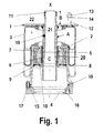
Nach Fig. 1 besitzt die Zwischenbuchse (5) an ihrer Innenwand eine Aussparung (23; Fig. 2), in der die Gleitbuchse mit etwa der halben Wandstärke einsitzt und dabei gleitend an der Außenwand der Rohrstange (A) anliegt. Ferner ist die Zwischenbuchse (5) an ihrer Außenwand ebenfalls mit einer Aussparung (24; Fig. 2) versehen, in der das Kugelgelenk (7) als dreischichtiger Metall-Elastomer-Verbund mit seinem Innenteil einsitzt. Zwecks Absicherung des Kugelgelenkes (7) und der Zwischenbuchse (5) sind zum Luftfederunterteil hin zwei Sicherungsringe (9, 18) vorhanden, wobei der Sicherungsring (18) in einer Einkerbung, die sich innerhalb der Außenwand der Zwischenbuchse befindet, einrastet. Die Rohrstange (A) umfaßt als Luftführung (19) wenigstens eine Öffnung, die den Stangeninnenraum (21) mit dem Luftfederraum (22) verbindet. Außerdem ist die Rohrstange (A) im Bereich (C) der Gleitbuchse (6) konisch ausgebildet, und zwar unter Vergrößerung des Durchmessers des Stangeninnenraumes (21).According to Fig. 1, the intermediate bush (5) on its inner wall has a recess (23; Fig. 2), in who sits the sliding bush with about half the wall thickness and while sliding on the The outer wall of the tubular rod (A) is in contact. Furthermore, the intermediate bush (5) is on its outer wall also provided with a recess (24; Fig. 2) in which the ball joint (7) as three-layer metal-elastomer composite with its inner part. In order to secure the Ball joint (7) and the intermediate bush (5) are two towards the lower air spring part Circlips (9, 18) are present, the circlip (18) in a notch that is located inside the outer wall of the intermediate bush. The tube rod (A) includes as an air duct (19) at least one opening that the rod interior (21) with the Air spring chamber (22) connects. In addition, the pipe rod (A) is in the area (C) of the sliding bush (6) conical, namely by increasing the diameter of the Rod interior (21).
Fig. 2 zeigt eine Luftführung (20), die innerhalb der Zwischenbuchse (5) in Achsrichtung (X; Fig. 1) angeordnet ist und dabei mit dem Luftfederraum in Verbindung steht. Die Luftführung besteht hier aus mehreren Außennuten, die im wesentlichen in gleichen Abständen über den gesamten Umfang der Zwischenbuchse (5) verteilt vorhanden sind. Die Zwischenbuchse ist an ihrer Innen- und Außenwand mit Aussparungen (23, 24) versehen, deren Bedeutung in Verbindung mit der Figurenbeschreibung 1 bereits dargelegt wurde.Fig. 2 shows an air duct (20) inside the intermediate bush (5) in the axial direction (X; Fig. 1) is arranged and is in communication with the air spring space. The air duct here consists of several outer grooves, which are at substantially the same intervals over the the entire circumference of the intermediate bushing (5) is distributed. The intermediate socket is on their inner and outer wall with recesses (23, 24), the meaning in Connection with the description of the figures 1 has already been set out.
Claims (17)
- Air spring, in particular for rail vehicles, commercial vehicles and buses, comprisingcharacterised in thata bellows (3) made of elastomer material which when necessary is provided with reinforcing inlays;a pot (2) to whose upper part the bellows (3) is secured, the bellows preferably rolling along the outer wall of the pot;a plate-shaped cover (1) which is disposed a distance from the pot (2) and to which the other end of the bellows (3) is secured;a centrally disposed rod (A) which is connected firmly to the cover (1) and in particular projects out of the cover by a distance (B), the rod also running parallel to the bellows (3) and passing into the pot (2);a ball joint (7) which is located between the pot (2) and the rod (A) and bears on the inner wall of the pot, the ball joint preferably being a metal-elastomer composite which has three layers and is formed of two layers of metal and one centrally disposed layer of elastomer, andan air duct (19, 20),a sliding bush (6) is disposed between the ball joint (7) and the rod (A), which bush bears slidingly on the outer wall of the rod, and furtheran intermediate bush (5) is present, which bush is located between the ball joint (7) and the sliding bush (6);the intermediate bush (5), the sliding bush (6) and the ball joint (7) surrounding the rod (A) cylindrically.
- Air spring according to claim 1, characterised in that the thickness of the elastomer layer of the ball joint (7) is 5 to 15 mm, in particular 6 to 10 mm.
- Air spring according to claim 1 or 2, characterised in that the diameter of the ball joint (7) is 100 to 200 mm, in particular 130 to 150 mm, related to the component with the smallest diameter.
- Air spring according to one of claims 1 to 3, characterised in that the rod (A) is tubular in form, in particular forming a rod inner space (21) running continuously in the axial direction (X).
- Air spring according to claim 4, characterised in that the inner wall of the tubular rod (A) is conical in form in the area (C) of the sliding bush (6), increasing the diameter of the rod inner space (21).
- Air spring according to one of claims 1 to 5, characterised in that the sliding bush (6) and the intermediate bush (5) are in each case formed in one piece.
- Air spring according to one of claims 1 to 6, characterised in that the sliding bush (6) is made of a sliding plastic, in particular of polytetrafluorethylene.
- Air spring according to one of claims 1 to 7, characterised in that the sliding bush (6) has a minimum wall thickness of 0.1 mm.
- Air spring according to one of claims 1 to 8, characterised in that in the axial direction (X) the sliding bush (6) exhibits a slot running obliquely and continuously.
- Air spring according to one of claims 1 to 9, characterised in that the intermediate bush (5) is made of a heat conducting material, in particular of aluminium.
- Air spring according to one of claims 1 to 10, characterised in that on its inner wall the intermediate bush (5) exhibits a recess (23) in which the sliding bush (6) sits with roughly half its wall thickness.
- Air spring according to one of claims 1 to 11, characterised in that on its outer wall the intermediate bush (5) exhibits a recess (24) in which the ball joint (7) sits with its inner part.
- Air spring according to one of claims 1 to 12, in particular in connection with claim 4, characterised in that the air duct (19) comprises at least one opening which connects the rod inner space (21) to the pneumatic spring space (22).
- Air spring according to one of claims 1 to 13, characterised in that the air duct (20) comprises at least one passage or outer groove which runs continuously and which is disposed inside the intermediate bush (5) in the axial direction (X) and communicates with the air spring space (22).
- Air spring according to claim 14, characterised in that the air duct (20) consists of a plurality of passages or outer grooves which essentially are present distributed at equal distances over the entire circumference of the intermediate bush (5).
- Air spring according to one of claims 1 to 15, characterised in that the ball joint (7) is secured towards the lower part of the pneumatic spring, in particular in the form of at least one circlip (9, 18).
- Air spring according to one of claims 1 to 16, characterised in that the intermediate bush (6) is secured towards the lower part of the pneumatic spring, in particular in the form of a circlip (18) which engages in a notch which is located inside the outer wall of the intermediate bush (5).
Applications Claiming Priority (3)
| Application Number | Priority Date | Filing Date | Title |
|---|---|---|---|
| DE19618168 | 1996-05-07 | ||
| DE19618168 | 1996-05-07 | ||
| PCT/DE1997/000854 WO1997042429A1 (en) | 1996-05-07 | 1997-04-28 | Pneumatic spring |
Publications (2)
| Publication Number | Publication Date |
|---|---|
| EP0897489A1 EP0897489A1 (en) | 1999-02-24 |
| EP0897489B1 true EP0897489B1 (en) | 1999-12-29 |
Family
ID=7793496
Family Applications (1)
| Application Number | Title | Priority Date | Filing Date |
|---|---|---|---|
| EP97922875A Expired - Lifetime EP0897489B1 (en) | 1996-05-07 | 1997-04-28 | Pneumatic spring |
Country Status (10)
| Country | Link |
|---|---|
| US (1) | US6168143B1 (en) |
| EP (1) | EP0897489B1 (en) |
| JP (1) | JP2000509475A (en) |
| CN (1) | CN1075608C (en) |
| AT (1) | ATE188279T1 (en) |
| AU (1) | AU2887097A (en) |
| DE (2) | DE19717892A1 (en) |
| ES (1) | ES2142164T3 (en) |
| HU (1) | HU221928B1 (en) |
| WO (1) | WO1997042429A1 (en) |
Cited By (1)
| Publication number | Priority date | Publication date | Assignee | Title |
|---|---|---|---|---|
| WO2007033626A1 (en) | 2005-09-22 | 2007-03-29 | Phoenix Traffic Technology Gmbh | Spring device, in particular for a driver's seat |
Families Citing this family (23)
| Publication number | Priority date | Publication date | Assignee | Title |
|---|---|---|---|---|
| US6733022B2 (en) * | 1998-12-01 | 2004-05-11 | Curtis S. Bradshaw | Air bag for sprint car |
| DE19959839A1 (en) * | 1998-12-14 | 2000-07-06 | Mannesmann Sachs Ag | Pneumatic spring with vibration damper for motor vehicle has connecting bearing installed in region of generated surface of cylinder tube and is circular in construction and equipped with sealing ring sealing off spring chamber |
| DE19922798A1 (en) * | 1999-05-18 | 2000-11-23 | Bayerische Motoren Werke Ag | Gas spring for a steerable vehicle wheel |
| US6843472B2 (en) * | 2003-01-21 | 2005-01-18 | The Pullman Company | Upper shock mount isolator with integral air spring housing pivot bearing |
| EP1629218A1 (en) * | 2003-06-04 | 2006-03-01 | Phoenix AG | Spring device, especially for the rail vehicle sector |
| DE102004033199A1 (en) * | 2004-07-09 | 2006-02-02 | Audi Ag | Air spring, in particular for a motor vehicle |
| DE102004048828A1 (en) * | 2004-10-07 | 2006-04-20 | Zf Friedrichshafen Ag | Air spring with a ball joint |
| DE102004050189A1 (en) * | 2004-10-15 | 2006-04-20 | Contitech Luftfedersysteme Gmbh | air spring |
| DE102005026314C5 (en) * | 2005-06-07 | 2008-09-25 | Lkh-Kunststoffwerk Gmbh & Co. Kg | Plastic plunger for an air spring |
| DE102005060332B3 (en) * | 2005-12-16 | 2007-02-15 | Zf Friedrichshafen Ag | Pneumatic spring leg e.g. for spring, has pneumatic spring with moving bellows which are connected to end of bearing |
| DE102006032208B3 (en) * | 2006-07-12 | 2008-02-21 | Zf Friedrichshafen Ag | Air spring with vibration damper |
| JP4985187B2 (en) * | 2007-07-30 | 2012-07-25 | 株式会社Ihi | Linear motion device |
| DE102008055509A1 (en) * | 2008-12-11 | 2010-06-17 | Contitech Luftfedersysteme Gmbh | air spring |
| NZ606896A (en) * | 2010-09-10 | 2014-12-24 | Hendrickson Usa Llc | Air spring for a heavy-duty vehicle with damping features |
| JP5722582B2 (en) * | 2010-09-28 | 2015-05-20 | 株式会社ブリヂストン | Air spring device |
| CN102486215B (en) * | 2010-12-02 | 2014-02-19 | 上海微电子装备有限公司 | Gravity compensation device |
| CN102588485A (en) * | 2011-01-07 | 2012-07-18 | 北京控股磁悬浮技术发展有限公司 | Air spring for suspension of maglev train |
| CN102330771A (en) * | 2011-07-12 | 2012-01-25 | 杨洁 | Compound air spring combined with air bag and inbuilt auxiliary air chamber |
| HUE027159T2 (en) | 2012-07-25 | 2016-08-29 | Vibracoustic Cv Air Springs Gmbh | Pneumatic springs |
| CN104912992B (en) * | 2014-03-14 | 2017-03-15 | 长春孔辉汽车科技股份有限公司 | Membrane type amplitude correlation vibroshock |
| JP6351823B2 (en) * | 2015-02-23 | 2018-07-04 | 三菱電機株式会社 | Heat-resistant structure of shaft support and actuator |
| RU2670846C9 (en) * | 2016-10-17 | 2019-04-03 | Общество с ограниченной ответственностью "Блэкстоун" | Universal pneumatic element suspension of the vehicle |
| CN110524573A (en) * | 2018-05-25 | 2019-12-03 | 长春工业大学 | A kind of flexibility artificial mechanism joint |
Family Cites Families (12)
| Publication number | Priority date | Publication date | Assignee | Title |
|---|---|---|---|---|
| US3854557A (en) * | 1970-02-04 | 1974-12-17 | Airpot Corp | Universal joint for piston-connecting rod assembly |
| US3765733A (en) * | 1971-09-13 | 1973-10-16 | Southwest Products Co | Bearing assembly |
| DE2342099A1 (en) * | 1973-08-21 | 1975-02-27 | Bergische Stahlindustrie | PULLING AND PUSHING DEVICE, IN PARTICULAR FOR LIGHT RAIL VEHICLES AND CABIN TRACKS |
| US3864922A (en) * | 1974-03-22 | 1975-02-11 | Halliburton Co | Sealed cushioning unit |
| DE3828203A1 (en) * | 1988-08-19 | 1990-03-01 | Georg Albersinger | Suspension and guide unit |
| DE4100296C1 (en) * | 1991-01-08 | 1992-06-11 | Mercedes-Benz Aktiengesellschaft, 7000 Stuttgart, De | |
| DE4203372C1 (en) | 1992-02-06 | 1993-03-04 | Bergische Achsenfabrik Fr. Kotz & Soehne, 5276 Wiehl, De | |
| TW235990B (en) | 1992-12-16 | 1994-12-11 | Taylor Gordon Joseph | |
| US5544715A (en) * | 1993-06-01 | 1996-08-13 | Edward H. Phillips-Techo Corp. | Method and apparatus for enhancing stability in servo systems comprising hydro-mechanically driven actuators |
| HUT69895A (en) * | 1993-09-27 | 1995-09-28 | Ikarus Jarmuegyarto Rt | Running gear suspension, mainly for low level floor bus |
| GB2284237A (en) * | 1993-11-30 | 1995-05-31 | Rose Bearings Ltd | Spherical bearing |
| JP2692574B2 (en) * | 1994-03-07 | 1997-12-17 | 鹿島建設株式会社 | Vertical damping device |
-
1997
- 1997-04-28 AT AT97922875T patent/ATE188279T1/en active
- 1997-04-28 CN CN97194444A patent/CN1075608C/en not_active Expired - Fee Related
- 1997-04-28 HU HU9901294A patent/HU221928B1/en not_active IP Right Cessation
- 1997-04-28 AU AU28870/97A patent/AU2887097A/en not_active Abandoned
- 1997-04-28 JP JP9539420A patent/JP2000509475A/en active Pending
- 1997-04-28 DE DE19717892A patent/DE19717892A1/en not_active Withdrawn
- 1997-04-28 DE DE59700938T patent/DE59700938D1/en not_active Expired - Lifetime
- 1997-04-28 ES ES97922875T patent/ES2142164T3/en not_active Expired - Lifetime
- 1997-04-28 US US09/171,725 patent/US6168143B1/en not_active Expired - Lifetime
- 1997-04-28 EP EP97922875A patent/EP0897489B1/en not_active Expired - Lifetime
- 1997-04-28 WO PCT/DE1997/000854 patent/WO1997042429A1/en active IP Right Grant
Cited By (1)
| Publication number | Priority date | Publication date | Assignee | Title |
|---|---|---|---|---|
| WO2007033626A1 (en) | 2005-09-22 | 2007-03-29 | Phoenix Traffic Technology Gmbh | Spring device, in particular for a driver's seat |
Also Published As
| Publication number | Publication date |
|---|---|
| DE19717892A1 (en) | 1997-11-13 |
| ES2142164T3 (en) | 2000-04-01 |
| EP0897489A1 (en) | 1999-02-24 |
| DE59700938D1 (en) | 2000-02-03 |
| HU221928B1 (en) | 2003-02-28 |
| CN1075608C (en) | 2001-11-28 |
| HUP9901294A3 (en) | 2000-02-28 |
| HUP9901294A2 (en) | 1999-08-30 |
| US6168143B1 (en) | 2001-01-02 |
| CN1218547A (en) | 1999-06-02 |
| JP2000509475A (en) | 2000-07-25 |
| WO1997042429A1 (en) | 1997-11-13 |
| AU2887097A (en) | 1997-11-26 |
| ATE188279T1 (en) | 2000-01-15 |
Similar Documents
| Publication | Publication Date | Title |
|---|---|---|
| EP0897489B1 (en) | Pneumatic spring | |
| DE102018210854B4 (en) | Air spring strut with a torsionally flexible rotary seal and chassis with one | |
| DE10150189A1 (en) | Vibration damping rubber bearing has elastomer annular body fitted outwardly radially to inner wall of outer shell | |
| EP0697298A2 (en) | Radially and axially loaded bush for motor vehicle suspension elements | |
| EP1693233A1 (en) | Air spring strut with centrally positioned damper | |
| EP1511950A1 (en) | Elastomer spring, especially for rail vehicles | |
| EP0485696A2 (en) | Elastic bearing | |
| DE10036740A1 (en) | Vibration damping device, the elastic body of which has good durability | |
| DE112013003500T5 (en) | Lateral support element, gas spring assembly and method | |
| EP2605923B1 (en) | Air strut with elastic piston mounting | |
| EP1611367A1 (en) | Hydraulically damping rubber bush bearing for vertical mounting | |
| EP0520187A1 (en) | Sliding and rotating bearing for radial and axial forces for suspension elements of motor vehicles | |
| EP1299658A1 (en) | Sleeve, particularly a rod sleeve | |
| DE3032199C1 (en) | Decoupled elastic strut mount | |
| DE4102002C2 (en) | Shock absorber | |
| DE69407331T2 (en) | Fastening element for connecting a spring-shock absorber unit to a vehicle body | |
| DE102012210388A1 (en) | Pneumatic spring module for suspension and attenuation of oscillations of chassis of motor car i.e. passenger car, has sealing element and damper bearing nested such that seal element partially projects into bearing in axial direction | |
| DE19625106C2 (en) | Vibration damper with short installation length | |
| EP1096161B1 (en) | Ball-joint | |
| EP2180204B1 (en) | Additional spring with slide | |
| DE102008000858B4 (en) | Bearing combination with bush bearing | |
| DE10006178C5 (en) | elastomeric bearings | |
| DE4420489C2 (en) | Ball joint | |
| DE102015224149A1 (en) | Hydraulic bearing bush | |
| EP1908987A2 (en) | Elastic bearing sleeve with hydraulic damping |
Legal Events
| Date | Code | Title | Description |
|---|---|---|---|
| PUAI | Public reference made under article 153(3) epc to a published international application that has entered the european phase |
Free format text: ORIGINAL CODE: 0009012 |
|
| 17P | Request for examination filed |
Effective date: 19980827 |
|
| AK | Designated contracting states |
Kind code of ref document: A1 Designated state(s): AT BE CH DE ES FR GB IT LI NL SE |
|
| GBC | Gb: translation of claims filed (gb section 78(7)/1977) | ||
| GRAG | Despatch of communication of intention to grant |
Free format text: ORIGINAL CODE: EPIDOS AGRA |
|
| GRAG | Despatch of communication of intention to grant |
Free format text: ORIGINAL CODE: EPIDOS AGRA |
|
| GRAH | Despatch of communication of intention to grant a patent |
Free format text: ORIGINAL CODE: EPIDOS IGRA |
|
| 17Q | First examination report despatched |
Effective date: 19990622 |
|
| GRAH | Despatch of communication of intention to grant a patent |
Free format text: ORIGINAL CODE: EPIDOS IGRA |
|
| GRAA | (expected) grant |
Free format text: ORIGINAL CODE: 0009210 |
|
| AK | Designated contracting states |
Kind code of ref document: B1 Designated state(s): AT BE CH DE ES FR GB IT LI NL SE |
|
| REF | Corresponds to: |
Ref document number: 188279 Country of ref document: AT Date of ref document: 20000115 Kind code of ref document: T |
|
| REG | Reference to a national code |
Ref country code: CH Ref legal event code: EP |
|
| REG | Reference to a national code |
Ref country code: CH Ref legal event code: NV Representative=s name: E. BLUM & CO. PATENTANWAELTE |
|
| REF | Corresponds to: |
Ref document number: 59700938 Country of ref document: DE Date of ref document: 20000203 |
|
| ET | Fr: translation filed | ||
| ITF | It: translation for a ep patent filed | ||
| REG | Reference to a national code |
Ref country code: ES Ref legal event code: FG2A Ref document number: 2142164 Country of ref document: ES Kind code of ref document: T3 |
|
| GBT | Gb: translation of ep patent filed (gb section 77(6)(a)/1977) |
Effective date: 20000310 |
|
| PLBE | No opposition filed within time limit |
Free format text: ORIGINAL CODE: 0009261 |
|
| STAA | Information on the status of an ep patent application or granted ep patent |
Free format text: STATUS: NO OPPOSITION FILED WITHIN TIME LIMIT |
|
| 26N | No opposition filed | ||
| REG | Reference to a national code |
Ref country code: GB Ref legal event code: IF02 |
|
| REG | Reference to a national code |
Ref country code: CH Ref legal event code: PFA Owner name: PHOENIX AKTIENGESELLSCHAFT Free format text: PHOENIX AKTIENGESELLSCHAFT#HANNOVERSCHE STRASSE 88#21079 HAMBURG (DE) -TRANSFER TO- PHOENIX AKTIENGESELLSCHAFT#HANNOVERSCHE STRASSE 88#21079 HAMBURG (DE) |
|
| PGFP | Annual fee paid to national office [announced via postgrant information from national office to epo] |
Ref country code: GB Payment date: 20140422 Year of fee payment: 18 |
|
| PGFP | Annual fee paid to national office [announced via postgrant information from national office to epo] |
Ref country code: NL Payment date: 20140418 Year of fee payment: 18 Ref country code: DE Payment date: 20140430 Year of fee payment: 18 Ref country code: ES Payment date: 20140428 Year of fee payment: 18 Ref country code: IT Payment date: 20140430 Year of fee payment: 18 Ref country code: FR Payment date: 20140422 Year of fee payment: 18 Ref country code: CH Payment date: 20140418 Year of fee payment: 18 Ref country code: SE Payment date: 20140418 Year of fee payment: 18 Ref country code: AT Payment date: 20140411 Year of fee payment: 18 |
|
| PGFP | Annual fee paid to national office [announced via postgrant information from national office to epo] |
Ref country code: BE Payment date: 20140418 Year of fee payment: 18 |
|
| REG | Reference to a national code |
Ref country code: DE Ref legal event code: R119 Ref document number: 59700938 Country of ref document: DE |
|
| REG | Reference to a national code |
Ref country code: CH Ref legal event code: PL |
|
| REG | Reference to a national code |
Ref country code: AT Ref legal event code: MM01 Ref document number: 188279 Country of ref document: AT Kind code of ref document: T Effective date: 20150428 Ref country code: SE Ref legal event code: EUG |
|
| GBPC | Gb: european patent ceased through non-payment of renewal fee |
Effective date: 20150428 |
|
| REG | Reference to a national code |
Ref country code: NL Ref legal event code: MM Effective date: 20150501 |
|
| PG25 | Lapsed in a contracting state [announced via postgrant information from national office to epo] |
Ref country code: GB Free format text: LAPSE BECAUSE OF NON-PAYMENT OF DUE FEES Effective date: 20150428 Ref country code: IT Free format text: LAPSE BECAUSE OF NON-PAYMENT OF DUE FEES Effective date: 20150428 Ref country code: CH Free format text: LAPSE BECAUSE OF NON-PAYMENT OF DUE FEES Effective date: 20150430 Ref country code: DE Free format text: LAPSE BECAUSE OF NON-PAYMENT OF DUE FEES Effective date: 20151103 Ref country code: LI Free format text: LAPSE BECAUSE OF NON-PAYMENT OF DUE FEES Effective date: 20150430 |
|
| REG | Reference to a national code |
Ref country code: FR Ref legal event code: ST Effective date: 20151231 |
|
| PG25 | Lapsed in a contracting state [announced via postgrant information from national office to epo] |
Ref country code: AT Free format text: LAPSE BECAUSE OF NON-PAYMENT OF DUE FEES Effective date: 20150428 Ref country code: FR Free format text: LAPSE BECAUSE OF NON-PAYMENT OF DUE FEES Effective date: 20150430 Ref country code: SE Free format text: LAPSE BECAUSE OF NON-PAYMENT OF DUE FEES Effective date: 20150429 |
|
| PG25 | Lapsed in a contracting state [announced via postgrant information from national office to epo] |
Ref country code: NL Free format text: LAPSE BECAUSE OF NON-PAYMENT OF DUE FEES Effective date: 20150501 |
|
| REG | Reference to a national code |
Ref country code: ES Ref legal event code: FD2A Effective date: 20160526 |
|
| PG25 | Lapsed in a contracting state [announced via postgrant information from national office to epo] |
Ref country code: ES Free format text: LAPSE BECAUSE OF NON-PAYMENT OF DUE FEES Effective date: 20150429 |
|
| PG25 | Lapsed in a contracting state [announced via postgrant information from national office to epo] |
Ref country code: BE Free format text: LAPSE BECAUSE OF NON-PAYMENT OF DUE FEES Effective date: 20150430 |