EP0897195A2 - Multicell electric storage battery - Google Patents
Multicell electric storage battery Download PDFInfo
- Publication number
- EP0897195A2 EP0897195A2 EP98500167A EP98500167A EP0897195A2 EP 0897195 A2 EP0897195 A2 EP 0897195A2 EP 98500167 A EP98500167 A EP 98500167A EP 98500167 A EP98500167 A EP 98500167A EP 0897195 A2 EP0897195 A2 EP 0897195A2
- Authority
- EP
- European Patent Office
- Prior art keywords
- lid
- battery
- cells
- terminals
- cylindrical
- Prior art date
- Legal status (The legal status is an assumption and is not a legal conclusion. Google has not performed a legal analysis and makes no representation as to the accuracy of the status listed.)
- Granted
Links
- 238000003860 storage Methods 0.000 title claims abstract description 8
- 238000004873 anchoring Methods 0.000 claims abstract description 6
- 239000002826 coolant Substances 0.000 claims abstract description 6
- 239000003792 electrolyte Substances 0.000 claims description 4
- 239000007789 gas Substances 0.000 claims description 3
- 238000005215 recombination Methods 0.000 claims description 3
- 230000006798 recombination Effects 0.000 claims description 3
- 239000002184 metal Substances 0.000 claims 1
- 229920006395 saturated elastomer Polymers 0.000 claims 1
- 230000006835 compression Effects 0.000 description 5
- 238000007906 compression Methods 0.000 description 5
- 238000000034 method Methods 0.000 description 4
- 239000011149 active material Substances 0.000 description 3
- 238000004519 manufacturing process Methods 0.000 description 3
- 239000002253 acid Substances 0.000 description 2
- 230000007797 corrosion Effects 0.000 description 2
- 238000005260 corrosion Methods 0.000 description 2
- QAOWNCQODCNURD-UHFFFAOYSA-N Sulfuric acid Chemical compound OS(O)(=O)=O QAOWNCQODCNURD-UHFFFAOYSA-N 0.000 description 1
- 230000001133 acceleration Effects 0.000 description 1
- 238000001816 cooling Methods 0.000 description 1
- 230000007423 decrease Effects 0.000 description 1
- 230000003247 decreasing effect Effects 0.000 description 1
- 230000006866 deterioration Effects 0.000 description 1
- 230000002542 deteriorative effect Effects 0.000 description 1
- 238000007599 discharging Methods 0.000 description 1
- 238000009826 distribution Methods 0.000 description 1
- 238000003487 electrochemical reaction Methods 0.000 description 1
- 238000010438 heat treatment Methods 0.000 description 1
- 150000002500 ions Chemical class 0.000 description 1
- 239000011148 porous material Substances 0.000 description 1
- 230000002028 premature Effects 0.000 description 1
- 238000002360 preparation method Methods 0.000 description 1
- 238000003908 quality control method Methods 0.000 description 1
- 230000001105 regulatory effect Effects 0.000 description 1
- 238000005476 soldering Methods 0.000 description 1
Images



Classifications
-
- H—ELECTRICITY
- H01—ELECTRIC ELEMENTS
- H01M—PROCESSES OR MEANS, e.g. BATTERIES, FOR THE DIRECT CONVERSION OF CHEMICAL ENERGY INTO ELECTRICAL ENERGY
- H01M10/00—Secondary cells; Manufacture thereof
- H01M10/60—Heating or cooling; Temperature control
- H01M10/61—Types of temperature control
- H01M10/613—Cooling or keeping cold
-
- H—ELECTRICITY
- H01—ELECTRIC ELEMENTS
- H01M—PROCESSES OR MEANS, e.g. BATTERIES, FOR THE DIRECT CONVERSION OF CHEMICAL ENERGY INTO ELECTRICAL ENERGY
- H01M10/00—Secondary cells; Manufacture thereof
- H01M10/06—Lead-acid accumulators
-
- B—PERFORMING OPERATIONS; TRANSPORTING
- B60—VEHICLES IN GENERAL
- B60L—PROPULSION OF ELECTRICALLY-PROPELLED VEHICLES; SUPPLYING ELECTRIC POWER FOR AUXILIARY EQUIPMENT OF ELECTRICALLY-PROPELLED VEHICLES; ELECTRODYNAMIC BRAKE SYSTEMS FOR VEHICLES IN GENERAL; MAGNETIC SUSPENSION OR LEVITATION FOR VEHICLES; MONITORING OPERATING VARIABLES OF ELECTRICALLY-PROPELLED VEHICLES; ELECTRIC SAFETY DEVICES FOR ELECTRICALLY-PROPELLED VEHICLES
- B60L50/00—Electric propulsion with power supplied within the vehicle
- B60L50/50—Electric propulsion with power supplied within the vehicle using propulsion power supplied by batteries or fuel cells
- B60L50/60—Electric propulsion with power supplied within the vehicle using propulsion power supplied by batteries or fuel cells using power supplied by batteries
- B60L50/64—Constructional details of batteries specially adapted for electric vehicles
-
- B—PERFORMING OPERATIONS; TRANSPORTING
- B60—VEHICLES IN GENERAL
- B60L—PROPULSION OF ELECTRICALLY-PROPELLED VEHICLES; SUPPLYING ELECTRIC POWER FOR AUXILIARY EQUIPMENT OF ELECTRICALLY-PROPELLED VEHICLES; ELECTRODYNAMIC BRAKE SYSTEMS FOR VEHICLES IN GENERAL; MAGNETIC SUSPENSION OR LEVITATION FOR VEHICLES; MONITORING OPERATING VARIABLES OF ELECTRICALLY-PROPELLED VEHICLES; ELECTRIC SAFETY DEVICES FOR ELECTRICALLY-PROPELLED VEHICLES
- B60L58/00—Methods or circuit arrangements for monitoring or controlling batteries or fuel cells, specially adapted for electric vehicles
- B60L58/10—Methods or circuit arrangements for monitoring or controlling batteries or fuel cells, specially adapted for electric vehicles for monitoring or controlling batteries
- B60L58/24—Methods or circuit arrangements for monitoring or controlling batteries or fuel cells, specially adapted for electric vehicles for monitoring or controlling batteries for controlling the temperature of batteries
- B60L58/26—Methods or circuit arrangements for monitoring or controlling batteries or fuel cells, specially adapted for electric vehicles for monitoring or controlling batteries for controlling the temperature of batteries by cooling
-
- H—ELECTRICITY
- H01—ELECTRIC ELEMENTS
- H01M—PROCESSES OR MEANS, e.g. BATTERIES, FOR THE DIRECT CONVERSION OF CHEMICAL ENERGY INTO ELECTRICAL ENERGY
- H01M10/00—Secondary cells; Manufacture thereof
- H01M10/06—Lead-acid accumulators
- H01M10/12—Construction or manufacture
- H01M10/121—Valve regulated lead acid batteries [VRLA]
-
- H—ELECTRICITY
- H01—ELECTRIC ELEMENTS
- H01M—PROCESSES OR MEANS, e.g. BATTERIES, FOR THE DIRECT CONVERSION OF CHEMICAL ENERGY INTO ELECTRICAL ENERGY
- H01M10/00—Secondary cells; Manufacture thereof
- H01M10/06—Lead-acid accumulators
- H01M10/12—Construction or manufacture
- H01M10/125—Cells or batteries with wound or folded electrodes
-
- H—ELECTRICITY
- H01—ELECTRIC ELEMENTS
- H01M—PROCESSES OR MEANS, e.g. BATTERIES, FOR THE DIRECT CONVERSION OF CHEMICAL ENERGY INTO ELECTRICAL ENERGY
- H01M10/00—Secondary cells; Manufacture thereof
- H01M10/60—Heating or cooling; Temperature control
- H01M10/62—Heating or cooling; Temperature control specially adapted for specific applications
- H01M10/625—Vehicles
-
- H—ELECTRICITY
- H01—ELECTRIC ELEMENTS
- H01M—PROCESSES OR MEANS, e.g. BATTERIES, FOR THE DIRECT CONVERSION OF CHEMICAL ENERGY INTO ELECTRICAL ENERGY
- H01M10/00—Secondary cells; Manufacture thereof
- H01M10/60—Heating or cooling; Temperature control
- H01M10/64—Heating or cooling; Temperature control characterised by the shape of the cells
- H01M10/643—Cylindrical cells
-
- H—ELECTRICITY
- H01—ELECTRIC ELEMENTS
- H01M—PROCESSES OR MEANS, e.g. BATTERIES, FOR THE DIRECT CONVERSION OF CHEMICAL ENERGY INTO ELECTRICAL ENERGY
- H01M10/00—Secondary cells; Manufacture thereof
- H01M10/60—Heating or cooling; Temperature control
- H01M10/65—Means for temperature control structurally associated with the cells
- H01M10/655—Solid structures for heat exchange or heat conduction
- H01M10/6551—Surfaces specially adapted for heat dissipation or radiation, e.g. fins or coatings
-
- H—ELECTRICITY
- H01—ELECTRIC ELEMENTS
- H01M—PROCESSES OR MEANS, e.g. BATTERIES, FOR THE DIRECT CONVERSION OF CHEMICAL ENERGY INTO ELECTRICAL ENERGY
- H01M10/00—Secondary cells; Manufacture thereof
- H01M10/60—Heating or cooling; Temperature control
- H01M10/65—Means for temperature control structurally associated with the cells
- H01M10/655—Solid structures for heat exchange or heat conduction
- H01M10/6554—Rods or plates
- H01M10/6555—Rods or plates arranged between the cells
-
- H—ELECTRICITY
- H01—ELECTRIC ELEMENTS
- H01M—PROCESSES OR MEANS, e.g. BATTERIES, FOR THE DIRECT CONVERSION OF CHEMICAL ENERGY INTO ELECTRICAL ENERGY
- H01M10/00—Secondary cells; Manufacture thereof
- H01M10/60—Heating or cooling; Temperature control
- H01M10/65—Means for temperature control structurally associated with the cells
- H01M10/655—Solid structures for heat exchange or heat conduction
- H01M10/6556—Solid parts with flow channel passages or pipes for heat exchange
- H01M10/6557—Solid parts with flow channel passages or pipes for heat exchange arranged between the cells
-
- H—ELECTRICITY
- H01—ELECTRIC ELEMENTS
- H01M—PROCESSES OR MEANS, e.g. BATTERIES, FOR THE DIRECT CONVERSION OF CHEMICAL ENERGY INTO ELECTRICAL ENERGY
- H01M10/00—Secondary cells; Manufacture thereof
- H01M10/60—Heating or cooling; Temperature control
- H01M10/65—Means for temperature control structurally associated with the cells
- H01M10/656—Means for temperature control structurally associated with the cells characterised by the type of heat-exchange fluid
- H01M10/6561—Gases
-
- H—ELECTRICITY
- H01—ELECTRIC ELEMENTS
- H01M—PROCESSES OR MEANS, e.g. BATTERIES, FOR THE DIRECT CONVERSION OF CHEMICAL ENERGY INTO ELECTRICAL ENERGY
- H01M10/00—Secondary cells; Manufacture thereof
- H01M10/60—Heating or cooling; Temperature control
- H01M10/65—Means for temperature control structurally associated with the cells
- H01M10/656—Means for temperature control structurally associated with the cells characterised by the type of heat-exchange fluid
- H01M10/6567—Liquids
-
- H—ELECTRICITY
- H01—ELECTRIC ELEMENTS
- H01M—PROCESSES OR MEANS, e.g. BATTERIES, FOR THE DIRECT CONVERSION OF CHEMICAL ENERGY INTO ELECTRICAL ENERGY
- H01M50/00—Constructional details or processes of manufacture of the non-active parts of electrochemical cells other than fuel cells, e.g. hybrid cells
- H01M50/10—Primary casings; Jackets or wrappings
- H01M50/147—Lids or covers
-
- H—ELECTRICITY
- H01—ELECTRIC ELEMENTS
- H01M—PROCESSES OR MEANS, e.g. BATTERIES, FOR THE DIRECT CONVERSION OF CHEMICAL ENERGY INTO ELECTRICAL ENERGY
- H01M50/00—Constructional details or processes of manufacture of the non-active parts of electrochemical cells other than fuel cells, e.g. hybrid cells
- H01M50/20—Mountings; Secondary casings or frames; Racks, modules or packs; Suspension devices; Shock absorbers; Transport or carrying devices; Holders
- H01M50/204—Racks, modules or packs for multiple batteries or multiple cells
- H01M50/207—Racks, modules or packs for multiple batteries or multiple cells characterised by their shape
- H01M50/213—Racks, modules or packs for multiple batteries or multiple cells characterised by their shape adapted for cells having curved cross-section, e.g. round or elliptic
-
- H—ELECTRICITY
- H01—ELECTRIC ELEMENTS
- H01M—PROCESSES OR MEANS, e.g. BATTERIES, FOR THE DIRECT CONVERSION OF CHEMICAL ENERGY INTO ELECTRICAL ENERGY
- H01M50/00—Constructional details or processes of manufacture of the non-active parts of electrochemical cells other than fuel cells, e.g. hybrid cells
- H01M50/20—Mountings; Secondary casings or frames; Racks, modules or packs; Suspension devices; Shock absorbers; Transport or carrying devices; Holders
- H01M50/249—Mountings; Secondary casings or frames; Racks, modules or packs; Suspension devices; Shock absorbers; Transport or carrying devices; Holders specially adapted for aircraft or vehicles, e.g. cars or trains
-
- H—ELECTRICITY
- H01—ELECTRIC ELEMENTS
- H01M—PROCESSES OR MEANS, e.g. BATTERIES, FOR THE DIRECT CONVERSION OF CHEMICAL ENERGY INTO ELECTRICAL ENERGY
- H01M50/00—Constructional details or processes of manufacture of the non-active parts of electrochemical cells other than fuel cells, e.g. hybrid cells
- H01M50/20—Mountings; Secondary casings or frames; Racks, modules or packs; Suspension devices; Shock absorbers; Transport or carrying devices; Holders
- H01M50/296—Mountings; Secondary casings or frames; Racks, modules or packs; Suspension devices; Shock absorbers; Transport or carrying devices; Holders characterised by terminals of battery packs
-
- H—ELECTRICITY
- H01—ELECTRIC ELEMENTS
- H01M—PROCESSES OR MEANS, e.g. BATTERIES, FOR THE DIRECT CONVERSION OF CHEMICAL ENERGY INTO ELECTRICAL ENERGY
- H01M50/00—Constructional details or processes of manufacture of the non-active parts of electrochemical cells other than fuel cells, e.g. hybrid cells
- H01M50/50—Current conducting connections for cells or batteries
- H01M50/543—Terminals
-
- H—ELECTRICITY
- H01—ELECTRIC ELEMENTS
- H01M—PROCESSES OR MEANS, e.g. BATTERIES, FOR THE DIRECT CONVERSION OF CHEMICAL ENERGY INTO ELECTRICAL ENERGY
- H01M50/00—Constructional details or processes of manufacture of the non-active parts of electrochemical cells other than fuel cells, e.g. hybrid cells
- H01M50/50—Current conducting connections for cells or batteries
- H01M50/572—Means for preventing undesired use or discharge
- H01M50/574—Devices or arrangements for the interruption of current
- H01M50/578—Devices or arrangements for the interruption of current in response to pressure
-
- H—ELECTRICITY
- H01—ELECTRIC ELEMENTS
- H01M—PROCESSES OR MEANS, e.g. BATTERIES, FOR THE DIRECT CONVERSION OF CHEMICAL ENERGY INTO ELECTRICAL ENERGY
- H01M50/00—Constructional details or processes of manufacture of the non-active parts of electrochemical cells other than fuel cells, e.g. hybrid cells
- H01M50/10—Primary casings; Jackets or wrappings
- H01M50/102—Primary casings; Jackets or wrappings characterised by their shape or physical structure
- H01M50/107—Primary casings; Jackets or wrappings characterised by their shape or physical structure having curved cross-section, e.g. round or elliptic
-
- H—ELECTRICITY
- H01—ELECTRIC ELEMENTS
- H01M—PROCESSES OR MEANS, e.g. BATTERIES, FOR THE DIRECT CONVERSION OF CHEMICAL ENERGY INTO ELECTRICAL ENERGY
- H01M50/00—Constructional details or processes of manufacture of the non-active parts of electrochemical cells other than fuel cells, e.g. hybrid cells
- H01M50/50—Current conducting connections for cells or batteries
- H01M50/502—Interconnectors for connecting terminals of adjacent batteries; Interconnectors for connecting cells outside a battery casing
- H01M50/509—Interconnectors for connecting terminals of adjacent batteries; Interconnectors for connecting cells outside a battery casing characterised by the type of connection, e.g. mixed connections
- H01M50/51—Connection only in series
-
- Y—GENERAL TAGGING OF NEW TECHNOLOGICAL DEVELOPMENTS; GENERAL TAGGING OF CROSS-SECTIONAL TECHNOLOGIES SPANNING OVER SEVERAL SECTIONS OF THE IPC; TECHNICAL SUBJECTS COVERED BY FORMER USPC CROSS-REFERENCE ART COLLECTIONS [XRACs] AND DIGESTS
- Y02—TECHNOLOGIES OR APPLICATIONS FOR MITIGATION OR ADAPTATION AGAINST CLIMATE CHANGE
- Y02E—REDUCTION OF GREENHOUSE GAS [GHG] EMISSIONS, RELATED TO ENERGY GENERATION, TRANSMISSION OR DISTRIBUTION
- Y02E60/00—Enabling technologies; Technologies with a potential or indirect contribution to GHG emissions mitigation
- Y02E60/10—Energy storage using batteries
-
- Y—GENERAL TAGGING OF NEW TECHNOLOGICAL DEVELOPMENTS; GENERAL TAGGING OF CROSS-SECTIONAL TECHNOLOGIES SPANNING OVER SEVERAL SECTIONS OF THE IPC; TECHNICAL SUBJECTS COVERED BY FORMER USPC CROSS-REFERENCE ART COLLECTIONS [XRACs] AND DIGESTS
- Y02—TECHNOLOGIES OR APPLICATIONS FOR MITIGATION OR ADAPTATION AGAINST CLIMATE CHANGE
- Y02P—CLIMATE CHANGE MITIGATION TECHNOLOGIES IN THE PRODUCTION OR PROCESSING OF GOODS
- Y02P70/00—Climate change mitigation technologies in the production process for final industrial or consumer products
- Y02P70/50—Manufacturing or production processes characterised by the final manufactured product
-
- Y—GENERAL TAGGING OF NEW TECHNOLOGICAL DEVELOPMENTS; GENERAL TAGGING OF CROSS-SECTIONAL TECHNOLOGIES SPANNING OVER SEVERAL SECTIONS OF THE IPC; TECHNICAL SUBJECTS COVERED BY FORMER USPC CROSS-REFERENCE ART COLLECTIONS [XRACs] AND DIGESTS
- Y02—TECHNOLOGIES OR APPLICATIONS FOR MITIGATION OR ADAPTATION AGAINST CLIMATE CHANGE
- Y02T—CLIMATE CHANGE MITIGATION TECHNOLOGIES RELATED TO TRANSPORTATION
- Y02T10/00—Road transport of goods or passengers
- Y02T10/60—Other road transportation technologies with climate change mitigation effect
- Y02T10/70—Energy storage systems for electromobility, e.g. batteries
Definitions
- the present invention relates to a multicell electric storage battery of the lead-acid type, used, for example, for the starting and semi-propulsion of automotive vehicles.
- the battery of the invention is of the conventional or recombinant type, whose container is generally right prismatic in shape, closed at the top by a lid through which the connecting terminals protrude, the container being subdivided internally into two or more cylindrical cells housing a positive and a negative electrode isolated by intermediate separators, all of which are wound in a spiral shape.
- the conventional design of the batteries used as energy sources in automobiles consists of a series of cells connected in series, each having a set number of positive and negative electrodes connected in parallel and separated physically by a porous material that permits the free circulation of the ions involved in the electrochemical reactions of charging and discharging.
- the cell design must be such that, on the one hand, the surface area of the electrodes can be large, regardless of the number of electrodes, and on the other hand, the active material can be maintained under a given mechanical pressure that keeps it from deteriorating during the charge and discharge cycles.
- This design can be implemented by means of cylindrical cells with spiral electrodes, in which the increase in the surface area of the electrode is limited solely by the thickness of the plates and separator. Moreover, the greater the surface area, the greater the internal pressure of the cell, and this pressure remains constant throughout the process owing to the circular geometry of the cell.
- New continuous manufacturing techniques permit the large-scale preparation of electrodes of very reduced thickness, and this, combined with automation of the assembly process, makes it possible to achieve the desired cost and performance goals by giving the electrodes a spiral configuration.
- one of the problems that arises in the batteries of the type described is the high temperature of the compartment where the battery is installed, due, in the case of the automobile, to the large number of heat-generating devices and the small available space, which greatly decreases the dissipation of heat.
- the high operating temperature of the battery increases electrode corrosion problems and causes deterioration of the active materials, thereby significantly reducing the life of the battery.
- batteries of the indicated type derives from the location or position of their connecting terminals. Depending on the structure of design of the automobile or other application, batteries must sometimes be mounted with the positive terminal on the right and sometimes with it on the left. In some cases the terminals must be on top of the lid, and in others on a side of the container.
- the object of the present invention is to provide a battery of the initially described type that eliminates the aforesaid disadvantages.
- the batteries comprise vertical throughpassing conduits that open through the lid and bottom and are disposed among adjacent cells. These conduits are designed for the natural or forced circulation of air or another coolant that serves to dissipate the heat of the battery, thereby increasing its service life.
- Another object of the present invention is to equip the battery with connecting terminals so disposed that they can be adapted to any type of vehicle, regardless of the arrangement of the positive and negative connectors.
- the battery comprises three connector terminals for each polarity, two of said terminals being disposed in the lid and a third in one of the walls of the container, the three terminals being connected electrically to one another by means of bars or bridges passing over the container, preferably inside the lid.
- the positive and negative electrical connections to the load can be made indiscriminately on either side of the battery, regardless of the position in which the battery is placed.
- Two of the above-discussed coolant conduits passing through the battery are used for the passage of anchoring rods for connection to the tray or soleplate on which the battery will be mounted.
- This fastening system lends the battery a high resistance to vibration and permits a smooth design for the container, since the traditional projections for anchoring the battery to the tray are no longer necessary.
- This system facilitates the mounting of the battery for both the manufacturer and the user of the vehicle.
- the cylindrical walls of the cells comprise a planar upper segment common to adjacent cells. This segment has an opening through which is performed the proper soldering of the connections between the different-polarity leads of these adjacent cells.
- This cell connection system further provides the advantage of greater ease of quality control and greater reliability for the storage battery.
- each cylindrical electrode includes a central core of perforated tubular configuration, the diameter of which defines the electrode capacity that can be housed in the annular chamber delimited by said core and the wall of the cell.
- the smaller the capacity required of the cell the larger the diameter of the core.
- the lid comprises handles that facilitate the handling and transport of the battery, these handles being collapsible and able to be housed on the surface of the lid when the battery is mounted or not in use.
- one or two hinged, symmetrical handles are disposed on the central part of the battery lid and are able to pivot about the hinge point between an idle position, in which they are folded down and fitted in channels formed in the surface of the lid, and a raised, operating position in which they are disposed perpendicular to the lid in order to serve as grips facilitating the transport and handling of the battery.
- the electrolyte will be absorbed in the separator, without complete saturation thereof, in such a way that no free electrolyte is present. Under these conditions the battery can be placed in any position, and thus a single handle arranged on one of the walls of the container can be used for handling and transport.
- This type of battery includes one valve per cell, designed to ensure the pressure needed to produce the internal recombination of the gases generated during the charging processes.
- the characteristics of the invention make it possible to obtain a battery that offers high rate performance and high plate compression, provided by cylindrical cells that guarantee high resistance to charge/discharge cycles, this being a battery that is convenient to handle, easy and safe to fasten or anchor, from which can be imparted a wide range of performance characteristics from its manufacturing process, and that incorporates an internal cell cooling system that prevents the battery from heating up during use, this being a very important advantage for the new applications of batteries in electric or hybrid vehicles, in which heat management of the battery is absolutely essential to ensure rapid recharging and the required acceleration peaks.
- Figure 1 is a perspective view of a battery realized according to the invention.
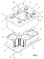
- Figure 2 is a view similar to that of Fig. 1, with the lid taken off.
- Figure 3 is a perspective view of a cross section of the battery of the invention, showing the distribution of the cells and the ventilating ducts.
- Figure 4 is a perspective view of the realization of the electrodes housed in each cell.
- the battery depicted in the drawings includes a container 1 of right prismatic configuration and rectangular shape in plan, closed at the top by means of a lid 2.
- the battery includes three terminals for each polarity, two negative terminals designated by reference numeral 3 and two positive terminals designated by reference numeral 4, which project through the lid, and one negative terminal 5 and another positive terminal 6 that project through one of the side walls.
- Terminals 3 and 5 are connected to one another by means of a bridge or bar that is integrated in the lid 2.
- terminals 4 and 6, of the same polarity are connected by another bar or bridge.
- Figure 2 shows the bridge 7 that joins terminals 3 of the same polarity.
- the appropriate bridges are extended to connect thereto.
- the battery shown in Figs. 1 and 2 also includes two handles, designated by reference numeral 8, which are hinged to lid 2 at their bottom ends and are able to flip between an operative position, in which the two handles 8 are disposed back to back in a position approximately perpendicular to lid 2, and an inoperative position, in which the handles 8 are folded down onto the lid 2 and are seated in channels 9 formed in the surface of said lid.
- the battery can include only one handle 8 hinged to lid 2 by the bottom ends of its arms, so that it can assume the positions described hereinabove.
- the battery could include a single handle disposed on one of the side walls of the container, as designated by reference numeral 8' in Fig. 1.
- the inside of the container 1 is subdivided into cylindrical cells 10 housing the spirally wound negative and positive electrodes and the corresponding separator.
- the cylindrical walls of these cells 10 comprise a planar upper segment 11, common to adjacent cells 10, which includes an access opening 12 through which the connection is made between the different-polarity leads 13 of the cells.
- vertical conduits 14 and 15 that open through openings 16 in the bottom and lid, defining ventilating ducts through which air or another coolant can circulate, forced air optionally being used, as shown in Figs. 2 and 3, through a system of coolant supply conduits 16.
- Threaded rods 17 for anchoring the battery to the mounting tray can be inserted through the end conduits 15.
- slots 18 disposed in the lid of the battery are slots 18 containing ventilating and acid filling holes 19 and filled with battery acid. These holes further serve to house valves that ensure an adequate internal pressure in each cell, allowing the recombination of gases necessary for a recombinant or valve-regulated type of battery.
- the slot 18 is subsequently closed by means of the cover bar 20.
- the arrangement described yields a cooled battery with high electrical performance characteristics and high resistance to vibration imparted by the anchoring systems, further ensuring absolute leaktightness between cells due to the connecting system described.
- This problem is solved in the battery of the invention through the use in each cell of a plastic core 21 (Fig. 4) of perforated tubular configuration, onto which the positive and negative electrodes and the separator are wound.
- This core 21 can have different diameters, thereby defining the electrode capacity that can be housed in the annular chamber delimited between said core and the cylindrical wall of the cell 10, thus making it possible to adjust the length of the positive and negative plates 22 that can be inserted in each fixed-diameter cell, ensuring the compression of the cylindrical stack formed by the electrodes 22 and the separator 23.
- By increasing the diameter of the core 21 it is possible to manufacture lower-capacity batteries, with shorter plates 22, without the need to use excessively thick separators or resort to a smaller container and lid, the compression of the stack being maintained in order to ensure the proper functioning of the battery.
Landscapes
- Engineering & Computer Science (AREA)
- Chemical & Material Sciences (AREA)
- Chemical Kinetics & Catalysis (AREA)
- Electrochemistry (AREA)
- General Chemical & Material Sciences (AREA)
- Manufacturing & Machinery (AREA)
- Sustainable Development (AREA)
- Life Sciences & Earth Sciences (AREA)
- Sustainable Energy (AREA)
- Power Engineering (AREA)
- Transportation (AREA)
- Mechanical Engineering (AREA)
- Aviation & Aerospace Engineering (AREA)
- Secondary Cells (AREA)
- Primary Cells (AREA)
- Battery Mounting, Suspending (AREA)
- Sealing Battery Cases Or Jackets (AREA)
Abstract
Description
Claims (5)
- A multicell electric storage battery, which comprises a container of generally right prismatic shape, closed at the top by means of a lid through which the connecting terminals protrude, which container is subdivided internally into two or more cylindrical cells housing positive and negative electrodes segregated by intermediate separators, wound in a spiral shape, characterized in that the battery comprises vertical throughpassing conduits that open through the lid and bottom and are disposed among adjacent cells, such conduits are intended for the circulation of air or another coolant and for the passage of threaded rods for anchoring the battery to the mounting tray or soleplate; and in that the cylindrical walls of the cells comprise a planar upper segment common to adjacent cells, which includes an access opening through which the electrical connection is made between the different-polarity leads of said adjacent cells.
- A battery according to Claim 1, characterized in that it comprises three connector terminals for each polarity, two of said terminals being disposed in the lid and one in one of the walls, the three terminals of each polarity being connected electrically by means of a metal bar integrated in the lid.
- A battery according to Claim 1, characterized in that each cylindrical cell includes a central core of perforated tubular configuration, the diameter of which defines the positive and negative electrode capacity housed in the annular chamber delimited between said core and the wall of the cell.
- A battery according to Claim 1, the lid of which carries handles hingedly corrected to its central part, which are able to swivel between an idle position in which they are folded down onto the lid in a coplanar position, and a working position in which they are roughly perpendicular to the lid, characterized in that said lid comprises channels in which the handles are housed in their idle position.
- A battery according to claim 1, having the electrolyte absorbed in the separator, which is not completely saturated, characterized in that in comprises one valve per cell, which ensures the necessary pressure for the internal recombination of gases generated during charging periods.
Applications Claiming Priority (2)
| Application Number | Priority Date | Filing Date | Title |
|---|---|---|---|
| ES9701689 | 1997-07-30 | ||
| ES9701689A ES2134149B1 (en) | 1997-07-30 | 1997-07-30 | BATTERY OF ELECTRIC ACCUMULATORS. |
Publications (3)
| Publication Number | Publication Date |
|---|---|
| EP0897195A2 true EP0897195A2 (en) | 1999-02-17 |
| EP0897195A3 EP0897195A3 (en) | 2000-08-02 |
| EP0897195B1 EP0897195B1 (en) | 2004-03-31 |
Family
ID=8300245
Family Applications (1)
| Application Number | Title | Priority Date | Filing Date |
|---|---|---|---|
| EP19980500167 Expired - Lifetime EP0897195B1 (en) | 1997-07-30 | 1998-07-16 | Multicell electric storage battery |
Country Status (7)
| Country | Link |
|---|---|
| US (1) | US6007937A (en) |
| EP (1) | EP0897195B1 (en) |
| AT (1) | ATE263434T1 (en) |
| CA (1) | CA2220811C (en) |
| DE (1) | DE69822727T2 (en) |
| DK (1) | DK0897195T3 (en) |
| ES (2) | ES2134149B1 (en) |
Cited By (7)
| Publication number | Priority date | Publication date | Assignee | Title |
|---|---|---|---|---|
| EP0994523A1 (en) * | 1998-10-15 | 2000-04-19 | Makita Corporation | Battery pack with improved heat radiation and sealing |
| EP1030387A1 (en) * | 1999-02-15 | 2000-08-23 | Sony Corporation | Battery device loaded on a moving body |
| EP1030388A1 (en) * | 1999-02-15 | 2000-08-23 | Sony Corporation | Battery device for loading on a moving body |
| EP1282188A1 (en) * | 2001-07-31 | 2003-02-05 | Sociedad Espanola Del Acumulador Tudor, S.A. | Electric accumulator batteries |
| WO2010022599A1 (en) * | 2008-08-26 | 2010-03-04 | 广州市凯捷电源实业有限公司 | Replaceable sealed lead-acid storage battery with multifunction |
| WO2015082201A1 (en) * | 2013-12-04 | 2015-06-11 | Volkswagen Aktiengesellschaft | Battery unit and vehicle electrical system with a battery unit |
| WO2025077964A1 (en) * | 2023-10-09 | 2025-04-17 | Bayerische Motoren Werke Aktiengesellschaft | Battery cell and vehicle having the battery cell |
Families Citing this family (44)
| Publication number | Priority date | Publication date | Assignee | Title |
|---|---|---|---|---|
| US6270920B1 (en) | 1998-03-19 | 2001-08-07 | Sanyo Electric Co., Ltd. | Battery module and container for battery module |
| IT248760Y1 (en) * | 1999-04-01 | 2003-02-12 | Stocchiero Olimpio | BATTERY CONTAINER WITH INCREASED RIGIDITY WALLS |
| ES2179734B1 (en) * | 2000-06-13 | 2004-04-01 | SOCIEDAD ESPAñOLA DEL ACUMULADOR TUDOR, S.A. | BATTERIES OF ELECTRIC ACCUMULATORS. |
| USD449578S1 (en) | 2000-09-13 | 2001-10-23 | Thomas W. Rogers | Battery box top |
| US6528206B2 (en) * | 2001-01-22 | 2003-03-04 | SOCIEDAD ESPAñOLA DEL ACUMULADOR TUDOR, S.A. | Electric accumulator battery |
| US7045236B1 (en) * | 2001-08-10 | 2006-05-16 | Johnson Controls Technology Company | Heat and gas exchange system for battery |
| ES2192954B1 (en) | 2001-09-27 | 2005-03-01 | S.E. Acumulador Tudor, S.A. | BATTERY OF ELECTRIC ACCUMULATORS. |
| JP3565271B2 (en) * | 2001-11-19 | 2004-09-15 | 日産自動車株式会社 | Battery assembly and method of manufacturing the same |
| GB0412291D0 (en) * | 2004-06-02 | 2004-07-07 | Enersys Ltd | A battery |
| KR20080025366A (en) | 2005-04-29 | 2008-03-20 | 텐딕스 디벨롭먼트, 엘엘씨 | Radial Impulse Engines, Pumps and Compressor Systems and Related Operation Methods |
| US8456130B2 (en) * | 2005-11-18 | 2013-06-04 | Moto Boost International, Llc | Method and apparatus for utilizing recycled batteries to surface charge an automobile battery |
| FR2908557B1 (en) * | 2006-11-14 | 2009-02-06 | Vehicules Electr Societe Par A | ELECTRICAL BATTERY COMPRISING A MECHANICAL AND THERMAL CONDITIONING SYSTEM |
| TW200830609A (en) * | 2007-01-04 | 2008-07-16 | Wen-Chin Shiau | Double-side usable modularized battery case |
| US20080280198A1 (en) * | 2007-05-07 | 2008-11-13 | Ajith Kuttannair Kumar | Battery mechanical packaging |
| US7921946B2 (en) * | 2007-05-07 | 2011-04-12 | General Electric Company | System and method for cooling a battery |
| US20080276631A1 (en) * | 2007-05-07 | 2008-11-13 | Ajith Kuttannair Kumar | System and Method for Cooling a Battery |
| US8006626B2 (en) | 2007-05-07 | 2011-08-30 | General Electric Company | System and method for cooling a battery |
| US7770525B2 (en) | 2007-05-07 | 2010-08-10 | General Electric Company | System and method for segregating an energy storage system from piping and cabling on a hybrid energy vehicle |
| US20080293277A1 (en) * | 2007-05-23 | 2008-11-27 | Ajith Kuttannair Kumar | System and method for connecting a battery to a mounting system |
| CN201294238Y (en) * | 2008-02-01 | 2009-08-19 | 钟阳 | Column type lead accumulator |
| DE102008013188A1 (en) * | 2008-03-07 | 2009-09-17 | Johnson Controls Hybrid And Recycling Gmbh | Electrochemical accumulator and vehicle with an electrochemical accumulator |
| US20130071708A1 (en) * | 2009-10-21 | 2013-03-21 | OnePoint Solutions, L.L.C. | Battery |
| US20110225737A1 (en) * | 2010-03-17 | 2011-09-22 | Mattel, Inc. | Power Source Compartment for an Infant Support Structure |
| USD633863S1 (en) * | 2010-05-06 | 2011-03-08 | Exide Technologies | Spiral wound battery |
| USD633864S1 (en) * | 2010-05-06 | 2011-03-08 | Exide Technologies | Spiral wound battery |
| USD633865S1 (en) * | 2010-05-06 | 2011-03-08 | Exide Technologies | Spiral wound battery |
| CA2747585C (en) * | 2010-07-27 | 2020-05-26 | Ark Corporation Pty Ltd | Charging apparatus and portable power supply |
| USD675562S1 (en) | 2010-11-05 | 2013-02-05 | Exide Technologies | Spiral wound battery |
| US9859532B2 (en) * | 2011-03-31 | 2018-01-02 | Johnson Controls Technology Llc | Battery module and method incorporating exterior casing and liner |
| US9991730B2 (en) | 2011-09-07 | 2018-06-05 | Johnson Controls Technology Company | Battery charging devices and systems |
| USD665342S1 (en) | 2011-10-28 | 2012-08-14 | Exide Technologies | Battery container |
| USD665343S1 (en) | 2011-10-28 | 2012-08-14 | Exide Technologies | Battery container |
| US10096813B2 (en) * | 2013-11-15 | 2018-10-09 | Saft Groupe Sa | Battery design with bussing integral to battery assembly |
| USD780686S1 (en) * | 2014-08-05 | 2017-03-07 | Wacker Neuson Produktion GmbH & Co. KG | Battery pack |
| USD762165S1 (en) * | 2014-10-01 | 2016-07-26 | Techtronic Industries Co. Ltd. | Battery pack |
| USD755715S1 (en) * | 2014-11-25 | 2016-05-10 | Mathew Inskeep | Battery charger |
| US9620764B2 (en) * | 2015-01-05 | 2017-04-11 | Johnson Controls Technology Company | Battery module cooling fins and footings system and method |
| JP6828296B2 (en) * | 2016-08-09 | 2021-02-10 | 株式会社Gsユアサ | Power storage device and charge control method for power storage device |
| USD913928S1 (en) * | 2018-11-09 | 2021-03-23 | West Affum Holdings Corp. | Handle and latching mechanism for a removable battery |
| US11844954B2 (en) | 2017-11-09 | 2023-12-19 | West Affum Holdings Dac | WCD monitor supporting serviceability and reprocessing |
| USD1119796S1 (en) * | 2021-08-05 | 2026-03-24 | Transportation Ip Holdings, Llc | Battery cell stack end cap |
| JP2024072524A (en) * | 2022-11-16 | 2024-05-28 | スズキ株式会社 | Battery pack |
| USD1078615S1 (en) * | 2025-03-30 | 2025-06-10 | Qiufei Yang | Battery case |
| USD1081543S1 (en) * | 2025-03-30 | 2025-07-01 | Qiufei Yang | Battery case |
Family Cites Families (20)
| Publication number | Priority date | Publication date | Assignee | Title |
|---|---|---|---|---|
| US1362554A (en) * | 1919-11-20 | 1920-12-14 | Balzano James | Storage battery |
| US4107402A (en) * | 1977-09-22 | 1978-08-15 | Globe-Union Inc. | Battery and battery container having air-flow passages therethrough |
| AU7309281A (en) * | 1980-07-23 | 1982-01-28 | Chloride Silent Power Ltd. | Electrochemical storage batteries and modules therefor |
| US4383011A (en) * | 1980-12-29 | 1983-05-10 | The Gates Rubber Company | Multicell recombining lead-acid battery |
| AU570352B2 (en) * | 1985-01-17 | 1988-03-10 | Furukawa Denchi Kabushiki Kaisha | Reduced height electrodes in storage battery |
| FR2608321B1 (en) * | 1986-12-12 | 1989-02-10 | Accumulateurs Fixes | ELECTROCHEMICAL GENERATOR WITH LITHIUM ANODE AND LIQUID CATHODE |
| US4859547A (en) * | 1987-10-06 | 1989-08-22 | Gates Energy Products, Inc. | Battery terminal and method |
| US4780379A (en) * | 1987-10-06 | 1988-10-25 | Gates Energy Products, Inc. | Multicell recombinant lead-acid battery with vibration resistant intercell connector |
| USD304927S (en) | 1988-05-13 | 1989-12-05 | Gates Energy Products, Inc. | Battery |
| USD303373S (en) | 1988-05-13 | 1989-09-12 | Gates Energy Products, Inc. | Battery |
| USD304926S (en) | 1988-05-13 | 1989-12-05 | Gates Energy Products, Inc. | Battery |
| USD307886S (en) | 1988-05-13 | 1990-05-15 | Gates Energy Products, Inc. | Battery |
| USD307133S (en) | 1988-05-13 | 1990-04-10 | Gates Energy Products, Inc. | Battery |
| FR2662121B1 (en) * | 1990-05-17 | 1992-11-06 | Hue Francis | DEVICE FOR SUPPLYING ELECTRICAL ENERGY TO A VEHICLE. |
| US5091273A (en) * | 1990-06-11 | 1992-02-25 | Optima Batteries, Inc. | Method of applying a tail wrap to a wound electrochemical cell and cell produced by the method |
| US5283137A (en) * | 1991-04-29 | 1994-02-01 | Optima Batteries, Inc. | Cover assembly for rechargeable battery |
| JP3276986B2 (en) * | 1992-06-29 | 2002-04-22 | 日本電産コパル株式会社 | Open / close door mechanism |
| US5599641A (en) * | 1994-04-20 | 1997-02-04 | Gylling Optima Batteries Ab | Battery terminal and case structure |
| JP3271495B2 (en) * | 1995-10-24 | 2002-04-02 | 松下電器産業株式会社 | Battery pack |
| US5871862A (en) * | 1997-05-08 | 1999-02-16 | Optima Batteries, Inc. | Battery paste compositions and electrochemical cells for use therewith |
-
1997
- 1997-07-30 ES ES9701689A patent/ES2134149B1/en not_active Expired - Fee Related
- 1997-10-27 US US08/958,278 patent/US6007937A/en not_active Expired - Lifetime
- 1997-11-12 CA CA 2220811 patent/CA2220811C/en not_active Expired - Fee Related
-
1998
- 1998-07-16 DE DE1998622727 patent/DE69822727T2/en not_active Expired - Lifetime
- 1998-07-16 EP EP19980500167 patent/EP0897195B1/en not_active Expired - Lifetime
- 1998-07-16 DK DK98500167T patent/DK0897195T3/en active
- 1998-07-16 ES ES98500167T patent/ES2217523T3/en not_active Expired - Lifetime
- 1998-07-16 AT AT98500167T patent/ATE263434T1/en not_active IP Right Cessation
Cited By (11)
| Publication number | Priority date | Publication date | Assignee | Title |
|---|---|---|---|---|
| EP0994523A1 (en) * | 1998-10-15 | 2000-04-19 | Makita Corporation | Battery pack with improved heat radiation and sealing |
| US6537694B1 (en) | 1998-10-15 | 2003-03-25 | Makita Corporation | Battery pack with improved heat radiation and sealing |
| US7211347B2 (en) | 1998-10-15 | 2007-05-01 | Makita Corporation | Battery packs having improved heat radiation |
| EP1030387A1 (en) * | 1999-02-15 | 2000-08-23 | Sony Corporation | Battery device loaded on a moving body |
| EP1030388A1 (en) * | 1999-02-15 | 2000-08-23 | Sony Corporation | Battery device for loading on a moving body |
| US6379837B1 (en) | 1999-02-15 | 2002-04-30 | Sony Corporation | Battery device loaded on moving body |
| EP1282188A1 (en) * | 2001-07-31 | 2003-02-05 | Sociedad Espanola Del Acumulador Tudor, S.A. | Electric accumulator batteries |
| WO2010022599A1 (en) * | 2008-08-26 | 2010-03-04 | 广州市凯捷电源实业有限公司 | Replaceable sealed lead-acid storage battery with multifunction |
| WO2015082201A1 (en) * | 2013-12-04 | 2015-06-11 | Volkswagen Aktiengesellschaft | Battery unit and vehicle electrical system with a battery unit |
| CN105874631A (en) * | 2013-12-04 | 2016-08-17 | 大众汽车有限公司 | Battery unit and vehicle electrical system with battery unit |
| WO2025077964A1 (en) * | 2023-10-09 | 2025-04-17 | Bayerische Motoren Werke Aktiengesellschaft | Battery cell and vehicle having the battery cell |
Also Published As
| Publication number | Publication date |
|---|---|
| CA2220811A1 (en) | 1999-01-30 |
| ATE263434T1 (en) | 2004-04-15 |
| ES2134149B1 (en) | 2000-03-16 |
| US6007937A (en) | 1999-12-28 |
| CA2220811C (en) | 2005-05-17 |
| DE69822727T2 (en) | 2005-02-10 |
| EP0897195A3 (en) | 2000-08-02 |
| EP0897195B1 (en) | 2004-03-31 |
| DE69822727D1 (en) | 2004-05-06 |
| DK0897195T3 (en) | 2004-07-19 |
| ES2134149A1 (en) | 1999-09-16 |
| ES2217523T3 (en) | 2004-11-01 |
Similar Documents
| Publication | Publication Date | Title |
|---|---|---|
| EP0897195B1 (en) | Multicell electric storage battery | |
| CN101411003B (en) | Battery assembly, manufacturing method thereof, and vehicle with battery assembly | |
| US9331314B2 (en) | Battery module having electrochemical cells with integrally formed terminals | |
| KR101182427B1 (en) | Battery pack and vehicle therewith | |
| EP1139483B1 (en) | Fluid-cooled battery pack system | |
| US6528206B2 (en) | Electric accumulator battery | |
| US20200035967A1 (en) | Cylindrical secondary battery module and method for producing cylindrical secondary battery module | |
| US6858345B2 (en) | Wound bipolar lithium polymer batteries | |
| US20140050967A1 (en) | System for arranging and coupling battery cells in a battery module | |
| EP2172994B1 (en) | Battery module having electrochemical cells with integrally formed terminals | |
| WO2007080456A2 (en) | Electrochemical cell for hybrid electric vehicle applications | |
| KR20010042060A (en) | Battery system electrical connection apparatus and method | |
| EP2612391B1 (en) | Low aspect ratio spiral-wound vrla battery | |
| KR100599801B1 (en) | Secondary Battery and Battery Module | |
| WO2013187280A1 (en) | Battery for automotive electrical/electronic systems | |
| US20250233289A1 (en) | Battery cell, battery, and electric device | |
| US20110305932A1 (en) | Heat transfer layered electrodes | |
| US20200235372A1 (en) | System for arranging and coupling battery cells in a battery module | |
| US20240186642A1 (en) | Battery and method of allowing for volumetric expansion of battery cells within a battery | |
| US20190229385A1 (en) | Battery module and battery pack including same | |
| US20250279499A1 (en) | Battery module | |
| CN222995543U (en) | Battery housing, battery cell and battery | |
| US20260106258A1 (en) | Battery module and battery pack including the same | |
| CN216288690U (en) | Support structure, lithium ion battery and electrical equipment | |
| KR20250152860A (en) | Battery cell and battery pack and vehicle including the same |
Legal Events
| Date | Code | Title | Description |
|---|---|---|---|
| PUAI | Public reference made under article 153(3) epc to a published international application that has entered the european phase |
Free format text: ORIGINAL CODE: 0009012 |
|
| AK | Designated contracting states |
Kind code of ref document: A2 Designated state(s): AT DE DK ES FR GB IT SE |
|
| AX | Request for extension of the european patent |
Free format text: AL;LT;LV;MK;RO;SI |
|
| RIN1 | Information on inventor provided before grant (corrected) |
Inventor name: COLLADO PARRA, ERNESTO Inventor name: GUTIERREZ HEREDIA, JESUS Inventor name: RUIZ RODRIGUEZ, RAFAEL Inventor name: FULLEA GARCIA, JOSE |
|
| PUAL | Search report despatched |
Free format text: ORIGINAL CODE: 0009013 |
|
| AK | Designated contracting states |
Kind code of ref document: A3 Designated state(s): AT BE CH CY DE DK ES FI FR GB GR IE IT LI LU MC NL PT SE |
|
| AX | Request for extension of the european patent |
Free format text: AL;LT;LV;MK;RO;SI |
|
| RIC1 | Information provided on ipc code assigned before grant |
Free format text: 7H 01M 2/10 A, 7H 01M 10/12 B, 7H 01M 10/50 B |
|
| 17P | Request for examination filed |
Effective date: 20001013 |
|
| AKX | Designation fees paid |
Free format text: AT DE DK ES FR GB IT SE |
|
| GRAP | Despatch of communication of intention to grant a patent |
Free format text: ORIGINAL CODE: EPIDOSNIGR1 |
|
| GRAS | Grant fee paid |
Free format text: ORIGINAL CODE: EPIDOSNIGR3 |
|
| GRAA | (expected) grant |
Free format text: ORIGINAL CODE: 0009210 |
|
| AK | Designated contracting states |
Kind code of ref document: B1 Designated state(s): AT DE DK ES FR GB IT SE |
|
| REG | Reference to a national code |
Ref country code: GB Ref legal event code: FG4D |
|
| REF | Corresponds to: |
Ref document number: 69822727 Country of ref document: DE Date of ref document: 20040506 Kind code of ref document: P |
|
| REG | Reference to a national code |
Ref country code: DK Ref legal event code: T3 |
|
| REG | Reference to a national code |
Ref country code: ES Ref legal event code: FG2A Ref document number: 2217523 Country of ref document: ES Kind code of ref document: T3 |
|
| ET | Fr: translation filed | ||
| PLBE | No opposition filed within time limit |
Free format text: ORIGINAL CODE: 0009261 |
|
| STAA | Information on the status of an ep patent application or granted ep patent |
Free format text: STATUS: NO OPPOSITION FILED WITHIN TIME LIMIT |
|
| 26N | No opposition filed |
Effective date: 20050104 |
|
| PGFP | Annual fee paid to national office [announced via postgrant information from national office to epo] |
Ref country code: DK Payment date: 20090714 Year of fee payment: 12 |
|
| PGFP | Annual fee paid to national office [announced via postgrant information from national office to epo] |
Ref country code: SE Payment date: 20090717 Year of fee payment: 12 Ref country code: AT Payment date: 20090715 Year of fee payment: 12 |
|
| PG25 | Lapsed in a contracting state [announced via postgrant information from national office to epo] |
Ref country code: AT Free format text: LAPSE BECAUSE OF NON-PAYMENT OF DUE FEES Effective date: 20100716 |
|
| REG | Reference to a national code |
Ref country code: DK Ref legal event code: EBP |
|
| PG25 | Lapsed in a contracting state [announced via postgrant information from national office to epo] |
Ref country code: DK Free format text: LAPSE BECAUSE OF NON-PAYMENT OF DUE FEES Effective date: 20100802 |
|
| PG25 | Lapsed in a contracting state [announced via postgrant information from national office to epo] |
Ref country code: SE Free format text: LAPSE BECAUSE OF NON-PAYMENT OF DUE FEES Effective date: 20100717 |
|
| PGFP | Annual fee paid to national office [announced via postgrant information from national office to epo] |
Ref country code: GB Payment date: 20120711 Year of fee payment: 15 |
|
| PGFP | Annual fee paid to national office [announced via postgrant information from national office to epo] |
Ref country code: DE Payment date: 20120711 Year of fee payment: 15 Ref country code: FR Payment date: 20120719 Year of fee payment: 15 Ref country code: IT Payment date: 20120714 Year of fee payment: 15 |
|
| GBPC | Gb: european patent ceased through non-payment of renewal fee |
Effective date: 20130716 |
|
| REG | Reference to a national code |
Ref country code: FR Ref legal event code: ST Effective date: 20140331 |
|
| PG25 | Lapsed in a contracting state [announced via postgrant information from national office to epo] |
Ref country code: DE Free format text: LAPSE BECAUSE OF NON-PAYMENT OF DUE FEES Effective date: 20140201 Ref country code: GB Free format text: LAPSE BECAUSE OF NON-PAYMENT OF DUE FEES Effective date: 20130716 |
|
| REG | Reference to a national code |
Ref country code: DE Ref legal event code: R119 Ref document number: 69822727 Country of ref document: DE Effective date: 20140201 |
|
| PG25 | Lapsed in a contracting state [announced via postgrant information from national office to epo] |
Ref country code: IT Free format text: LAPSE BECAUSE OF NON-PAYMENT OF DUE FEES Effective date: 20130716 Ref country code: FR Free format text: LAPSE BECAUSE OF NON-PAYMENT OF DUE FEES Effective date: 20130731 |
|
| PGFP | Annual fee paid to national office [announced via postgrant information from national office to epo] |
Ref country code: ES Payment date: 20170801 Year of fee payment: 20 |
|
| REG | Reference to a national code |
Ref country code: ES Ref legal event code: FD2A Effective date: 20200721 |
|
| PG25 | Lapsed in a contracting state [announced via postgrant information from national office to epo] |
Ref country code: ES Free format text: LAPSE BECAUSE OF EXPIRATION OF PROTECTION Effective date: 20180717 |