EP0896559B1 - Method and apparatus for propelling a marine vessel - Google Patents
Method and apparatus for propelling a marine vessel Download PDFInfo
- Publication number
- EP0896559B1 EP0896559B1 EP97922660A EP97922660A EP0896559B1 EP 0896559 B1 EP0896559 B1 EP 0896559B1 EP 97922660 A EP97922660 A EP 97922660A EP 97922660 A EP97922660 A EP 97922660A EP 0896559 B1 EP0896559 B1 EP 0896559B1
- Authority
- EP
- European Patent Office
- Prior art keywords
- electrical energy
- boat
- transmission device
- generating
- circuit
- Prior art date
- Legal status (The legal status is an assumption and is not a legal conclusion. Google has not performed a legal analysis and makes no representation as to the accuracy of the status listed.)
- Expired - Lifetime
Links
Images




Classifications
-
- B—PERFORMING OPERATIONS; TRANSPORTING
- B63—SHIPS OR OTHER WATERBORNE VESSELS; RELATED EQUIPMENT
- B63H—MARINE PROPULSION OR STEERING
- B63H19/00—Marine propulsion not otherwise provided for
- B63H19/02—Marine propulsion not otherwise provided for by using energy derived from movement of ambient water, e.g. from rolling or pitching of vessels
-
- B—PERFORMING OPERATIONS; TRANSPORTING
- B60—VEHICLES IN GENERAL
- B60L—PROPULSION OF ELECTRICALLY-PROPELLED VEHICLES; SUPPLYING ELECTRIC POWER FOR AUXILIARY EQUIPMENT OF ELECTRICALLY-PROPELLED VEHICLES; ELECTRODYNAMIC BRAKE SYSTEMS FOR VEHICLES IN GENERAL; MAGNETIC SUSPENSION OR LEVITATION FOR VEHICLES; MONITORING OPERATING VARIABLES OF ELECTRICALLY-PROPELLED VEHICLES; ELECTRIC SAFETY DEVICES FOR ELECTRICALLY-PROPELLED VEHICLES
- B60L8/00—Electric propulsion with power supply from forces of nature, e.g. sun or wind
-
- B—PERFORMING OPERATIONS; TRANSPORTING
- B63—SHIPS OR OTHER WATERBORNE VESSELS; RELATED EQUIPMENT
- B63H—MARINE PROPULSION OR STEERING
- B63H13/00—Marine propulsion by wind motors driving water-engaging propulsive elements
-
- B—PERFORMING OPERATIONS; TRANSPORTING
- B63—SHIPS OR OTHER WATERBORNE VESSELS; RELATED EQUIPMENT
- B63B—SHIPS OR OTHER WATERBORNE VESSELS; EQUIPMENT FOR SHIPPING
- B63B2209/00—Energy supply or activating means
- B63B2209/18—Energy supply or activating means solar energy
-
- Y—GENERAL TAGGING OF NEW TECHNOLOGICAL DEVELOPMENTS; GENERAL TAGGING OF CROSS-SECTIONAL TECHNOLOGIES SPANNING OVER SEVERAL SECTIONS OF THE IPC; TECHNICAL SUBJECTS COVERED BY FORMER USPC CROSS-REFERENCE ART COLLECTIONS [XRACs] AND DIGESTS
- Y02—TECHNOLOGIES OR APPLICATIONS FOR MITIGATION OR ADAPTATION AGAINST CLIMATE CHANGE
- Y02E—REDUCTION OF GREENHOUSE GAS [GHG] EMISSIONS, RELATED TO ENERGY GENERATION, TRANSMISSION OR DISTRIBUTION
- Y02E10/00—Energy generation through renewable energy sources
- Y02E10/30—Energy from the sea, e.g. using wave energy or salinity gradient
-
- Y—GENERAL TAGGING OF NEW TECHNOLOGICAL DEVELOPMENTS; GENERAL TAGGING OF CROSS-SECTIONAL TECHNOLOGIES SPANNING OVER SEVERAL SECTIONS OF THE IPC; TECHNICAL SUBJECTS COVERED BY FORMER USPC CROSS-REFERENCE ART COLLECTIONS [XRACs] AND DIGESTS
- Y02—TECHNOLOGIES OR APPLICATIONS FOR MITIGATION OR ADAPTATION AGAINST CLIMATE CHANGE
- Y02E—REDUCTION OF GREENHOUSE GAS [GHG] EMISSIONS, RELATED TO ENERGY GENERATION, TRANSMISSION OR DISTRIBUTION
- Y02E10/00—Energy generation through renewable energy sources
- Y02E10/40—Solar thermal energy, e.g. solar towers
- Y02E10/46—Conversion of thermal power into mechanical power, e.g. Rankine, Stirling or solar thermal engines
-
- Y—GENERAL TAGGING OF NEW TECHNOLOGICAL DEVELOPMENTS; GENERAL TAGGING OF CROSS-SECTIONAL TECHNOLOGIES SPANNING OVER SEVERAL SECTIONS OF THE IPC; TECHNICAL SUBJECTS COVERED BY FORMER USPC CROSS-REFERENCE ART COLLECTIONS [XRACs] AND DIGESTS
- Y02—TECHNOLOGIES OR APPLICATIONS FOR MITIGATION OR ADAPTATION AGAINST CLIMATE CHANGE
- Y02T—CLIMATE CHANGE MITIGATION TECHNOLOGIES RELATED TO TRANSPORTATION
- Y02T10/00—Road transport of goods or passengers
- Y02T10/60—Other road transportation technologies with climate change mitigation effect
- Y02T10/7072—Electromobility specific charging systems or methods for batteries, ultracapacitors, supercapacitors or double-layer capacitors
-
- Y—GENERAL TAGGING OF NEW TECHNOLOGICAL DEVELOPMENTS; GENERAL TAGGING OF CROSS-SECTIONAL TECHNOLOGIES SPANNING OVER SEVERAL SECTIONS OF THE IPC; TECHNICAL SUBJECTS COVERED BY FORMER USPC CROSS-REFERENCE ART COLLECTIONS [XRACs] AND DIGESTS
- Y02—TECHNOLOGIES OR APPLICATIONS FOR MITIGATION OR ADAPTATION AGAINST CLIMATE CHANGE
- Y02T—CLIMATE CHANGE MITIGATION TECHNOLOGIES RELATED TO TRANSPORTATION
- Y02T70/00—Maritime or waterways transport
- Y02T70/50—Measures to reduce greenhouse gas emissions related to the propulsion system
- Y02T70/5218—Less carbon-intensive fuels, e.g. natural gas, biofuels
- Y02T70/5236—Renewable or hybrid-electric solutions
Definitions
- the present invention relates generally to a system for propelling marine vessels.
- the invention relates to an auxiliary propulsion system for sail-powered marine vessels that uses a combined electric motor and transmission device having a continuously variable speed output, a stored energy supply for powering the device, and an electrical recharging system for recharging the stored energy supply.
- auxiliary power sources for use during low wind conditions or for maneuvering in and out of harbors and slips.
- auxiliary power sources typically consist of internal combustion engines or electrically powered motors. Both of these power sources have inherent disadvantages as will be discussed below.
- Internal combustion engines require constant maintenance and often become environmental hazards after extended use or inadequate maintenance.
- internal combustion engines require the use of oil-based fuels and lubricants that can leak and emit unpleasant, unsightly and unsafe odors.
- internal combustion engines are comparatively loud, and often can become unreliable due to age or constant exposure to the saltwater and extreme weather conditions common to the environment of marine vessels.
- the necessary fuel system and engine block are bulky and add unwanted weight to marine vessels.
- any supply of fuels and lubricants on a marine vessel can occupy a considerable amount of a vessel's limited space, and also pose a fire hazard to the vessel and its occupants.
- electric motors used in marine vessels are generally quieter, less polluting and require less maintenance than internal combustion engines.
- electric motors also suffer from a number of inherent problems. Electric motors are usually powered by batteries, which cannot operate for extended periods of time without recharging. During normal operation, marine vessels are often far from shore and do not have a recharging source. Large banks of batteries may be employed to prolong the amount of time between battery rechargings. However, like the fuel tanks, the engine block and the required supplies for an internal combustion engine, the large banks of batteries needed to run conventional electric motors can be bulky and heavy.
- Marine vessels are operated in environments having almost unlimited energy sources.
- sail-powered marine vessels use the wind as their primary motive power source.
- such vessels are typically exposed to several hours of direct sunlight, and are surrounded by water that is constantly in motion.
- the movement of vessels under sail by itself can generate the movement of water.
- the wind, sun and water offer sources of energy which could potentially help power marine vessels.
- United States Patent No. 1 181 988 provides a system having a simple electric motor or internal combustion engine or windmill that may or may not be clutched into a propulsion drive train.
- United States Patent No. 5 131 341 describes a system for producing and distributing electric power on a sailing ship, using arrays of photovoltaic cells covering the ships sails and rigging.
- UK Patent Application Publication No. 2 075 610 describes a floating vessel with a plurality of downwardly open cylinders each containing a piston and valves, for converting wave motion to useful energy.
- the present invention relates to an auxiliary propulsion system for a boat or other marine vessel as claimed in claim 1.
- a general object of the present invention is to provide an apparatus and method for an auxiliary propulsion system for a sail-powered marine vessel.
- a further general object is to provide an apparatus and method for an electrically-based auxiliary propulsion system for a sail-powered marine vessel.
- Another general object is to provide an apparatus and method for recharging an electrically-based auxiliary propulsion system for a sail-powered marine vessel.
- An even further object of the invention is to provide an apparatus and method for an electrically-based auxiliary propulsion system for a sail-powered marine vessel that requires less room, or is at least more space efficient, than conventional auxiliary propulsion systems.
- An even further object is to provide an apparatus and method for a propulsion system for marine vessels that can harness the energies of the wind, sun or water to a greater degree than current conventional marine vessels.
- the apparatus of the auxiliary propulsion system generally incorporates means for generating locomotive force to propel the boat or vessel wherein the locomotive means includes an electric motor/transmission device, means for storing energy for the electric motor/transmission device, and means for generating energy from one of at least sunlight, wind motion and water motion to be stored in the energy storing means.
- the auxiliary propulsion system for a boat or other marine vessel incorporates an electric motor/transmission device for generating locomotive force to propel the boat or vessel; an electrical power supply for providing electrical energy to drive the electric motor/transmission device; at least one electrical energy generating device for generating electrical energy through conversion from one of at least sunlight, wind motion and water motion; a charging circuit having means for controlling charging of the power supply with electrical energy from the energy generating device; and means for controlling speed and direction operation of the electric motor/transmission device.
- a method for providing auxiliary propulsion for a boat or other marine vessel comprises the steps of providing an electric motor/transmission device; inputting electrical energy into the electric motor/transmission device from an electric power supply; generating locomotive force for the boat or other marine vessel using the electric motor/transmission device when a primary propulsion system of the boat or other marine vessel is inactive; and generating electrical energy to be stored in the electrical power supply.
- the step of generating electrical energy includes the step of converting at least one of sunlight, wind motion and water motion into electrical energy.
- the propulsion system 10 of the present invention is generally embodied in a variable speed electric motor/transmission 12 connected through a shaft to a propeller 14.
- the motor/transmission 12 is a dual-input, infinite-speed electrically powered motor/transmission device.
- an electric motor/transmission includes a sun gear motor powering a sun gear assembly, a ring gear motor powering a ring gear assembly and a transmission assembly.
- the ring gear assembly can be rotated in a forward or reverse direction at an infinite number of speeds.
- the sun gear assembly may be rotated in a forward direction, a reverse direction or may be locked in a stationary position.
- the electric motor/transmission 12 drives the propeller 14, thereby propelling the vessel (not shown) in which the system is installed.
- the direct connection from the electric motor/transmission 12 to the propeller allows substantially all of the torque developed by motor/transmission 12 to be transmitted directly to propeller 14.
- the electric motor/transmission 12 is further connected to a speed control circuit 16 that varies the electrical power to the electric motor/transmission 12, thereby varying the speed of the electric motor/transmission 12 and the propeller 14. Consequently, varying the speed of the propeller varies the speed of the vessel.
- the speed control circuit 16 is connected to a user control panel 18. From the user control panel 18, the speed of the vessel or the amount of power to apply to the propulsion system 10, along with the direction of rotation of the propeller 14 to effect either forward or reverse motion can be selected.
- the speed control circuit 16 controls the amount of electric power inputted to the electric motor/transmission 12 from the power supply circuit 20. Since a preferred embodiment of the present invention is primarily directed to be an auxiliary propulsion system for a sail-powered marine vessel, one conventional implementation of the power supply circuit 20 is a bank of batteries, such as car batteries. However, other types of high capacity electric storage cells may be used for the power supply circuit 20. For example, commercial versions of the battery cells used in modem diesel submarines may be applicable.
- the speed control circuit 16 can be implemented using a conventional microprocessor-based control circuit (not shown) as known in the art, wherein user inputs (i.e. , pushing of a button, shifting of a lever, rotating of a dial) into the user control panel 18 are translated into control signals. The control signals are then inputted into the speed control circuit 16. The control signals are then interpreted by the microprocessor-based circuit of the speed control circuit 16 to control the amount of electric power to be fed to the electric motor/transmission 12.
- the power supply 20 is replenished with electrical energy through a charging circuit 22.
- the charging circuit 22 controls and regulates the voltage and current levels inputted into the system for recharging the power supply 20.
- the charging circuit 22 as shown in Figure 7 can include monitoring circuitry 22a for monitoring and signalling which batteries in a bank of batteries 20a need replenishment or replacement.
- the charging circuit 22 can include switching circuitry 22b for selectively charging the batteries; in order to either evenly regulate the charging of the batteries or to charge only the batteries that require charging.
- a charging control circuit 22c is connected to receive and process signal data from the monitoring circuitry 22a and to control the switching and charging operation of the switching circuitry 22b.
- the charging circuit 22 is further connected to at least one electrical energy input source 24 and an external energy source 26.
- the electrical input source 24 is embodied in an electrical energy generating device or system that can generate electrical energy with which to charge the power supply 20 while the boat/vessel is moving under sail or even while it is stationary away from the docks.
- electrical energy generating devices include, as shown in Figures 4A through 4C , solar panels composed of an array of photoelectric cells ( Figure 4A ), wind-powered generators ( Figure 4B ), and water- or wave-powered generators ( Figure 4C ).
- a wind-powered generator is a windmill-type device consisting of an electrical generator 24b with a propeller 25 that rotates with the wind.
- the water- or wave-powered generator incorporates the electric motor/transmission 12 that is coupled to a regenerative feedback circuit 24c and its accompanying circuitry (not shown).
- This wave-powered generator operates while the boat/vessel is moving under sail. As the boat/vessel moves, the movement of the boat/vessel through the water forces water passing underneath the boat or vessel to move through the propeller 14 that is idle when the electric motor/transmission 12 is not operating.
- the direct connection between the propeller and the electric motor/transmission 12 causes the movement of the water to rotate the propeller 14 and the electric motor/transmission 12, thereby operating the electric motor/transmission 12 as an electric generator, opposite its normal operation as an electric motor.
- the electrical energy generated by the electric motor/transmission 12 is fed through the regenerative feedback loop 24c to the power supply 20.
- the external energy source 26 may be embodied by any conventional power supply or generator system external to the power supply 20 and the various types of electric input sources 24.
- one type of external energy source is the conventional 115-volt heavy-duty outlet available at typical docks and ports.
- Another example is the conventional gasoline-powered generator which can either be located at a dock or be carried on the boat/vessel.
- the speed control circuit 16 is embodied in a sun speed controller 116 and a ring speed controller 117.
- the operation of each of these controllers is determined by the inputs generated through the user control panel 18.
- the electric motor/transmission 12 includes a sun gear motor powering a sun gear assembly; a ring gear motor powering a ring gear assembly; and a transmission assembly (all not shown).
- the sun speed controller 116 controls the electrical energy fed to the sun gear motor, thereby controlling the speed and torque of the sun gear motor and its corresponding sun gear assembly.
- the ring speed controller 117 controls the electrical energy fed to the ring gear motor, thereby controlling the speed and torque of the ring gear motor and its corresponding ring gear and transmission assemblies.
- the power supply 20 is embodied in a main power supply 120 that supplies the electrical energy for operating the sun and ring gear motors of the electric motor/transmission, and a control power supply 121 that powers the sun and ring gear controllers 116, 117.
- the charging circuit 22 is configured to receive and regulate electrical energy from not only the electrical input source 24, but also from a conventional 115 volt heavy-duty outlet 126 and an external generator 127 (i.e., a gasoline-powered generator). Further, the charging circuit 22 regulates the electrical energy inputted into each of the main and control power supplies 120, 121 for recharging them.
- the electric motor/transmission 12 is connected to the main power supply 120 through a regenerative feedback circuit 28 that includes the regenerative feedback loop 24c shown in Figure 4C .
- the regenerative feedback circuit 28 receives electrical energy from the electric motor/transmission 12 when it operates as a generator (as explained above), and feeds that energy to recharge the main power supply 120 directly.
- the regenerative feedback circuit 28 in one embodiment (not shown) can incorporate monitoring circuitry for monitoring and signalling which batteries in a bank of batteries need replenishment or replacement, and switching circuitry for selectively charging the batteries, in order to either evenly regulate the charging of the batteries or to charge only the batteries that require charging.
- one embodiment for the user control panel 18, in accordance with the system of the present invention shown in Figure 2 comprises an ENABLE switch 181, a direction control device 182, and a speed control device 183.
- ENABLE switch 181 may be embodied in a conventional momentary contact switch, while the direction control device 182 and the speed control device 183 may be embodied in conventional variable position levers.
- Both the direction control device 182 and the speed control device 183 are connected to send corresponding control signals to the sun speed controller 116 and to the ring speed controller 117.
- the ENABLE switch 181 controls activation of the user control panel 18, for example, by controlling the connection to the control power supply 121.
- the direction control device 182 outputs direction control signals to both the sun speed controller 116 and the ring speed controller 117 determining whether the electric motor/transmission 12 will operate and propel the boat/vessel in a forward (setting F) or reverse (setting R) direction, or remain in an idle or neutral (setting N) state.
- the speed control device 183 outputs speed control signals to the sun speed controller 116 and the ring speed controller 117, determining the speed and torque output levels of the sun gear motor and the ring gear motor. As illustrated in Figure 3 , the speed control device 183 is structured to vary between maximum (setting MAX) and minimum (setting MIN) output levels of the motors, and to output speed control signals corresponding to a selected output level.
- One technique for implementing the speed control device 183, as well as the direction control device 182 involves the use of a microprocessor-controlled circuit (not shown) as known in the art. The positions of the two control devices are translated by the microprocessor-controlled circuit into the corresponding direction and speed control signals. Those direction and speed control signals are then inputted into the sun speed controller 116 and the ring speed controller 117. The sun speed controller 116 and the ring speed controller 117 in turn use the control signals to regulate the electric energy fed to the electric motor/transmission 12.
- An alternative technique for implementing the direction and speed control devices 182, 183 involves structuring the control devices to output analog or digital signals indicative of their respective positions (i.e., F versus R, MAX versus MIN). The outputted signals from the control devices are then inputted into each of the sun speed controller 116 and the ring speed controller 117.
- both the sun speed controller 116 and the ring speed controller 117 are implemented using microprocessor-controlled circuits (not shown).
- the sun speed controller 116 and the ring speed controller 117 translate the outputted signals from the user control panel 18, and respectively regulate the operation of the electric motor/transmission 12.
- a further alternative technique for implementing the direction and speed control devices 182, 183 of the user control panel 18, as well as the sun speed and ring speed controllers 116, 117 involves the use of microprocessor-controlled circuits in the user control panel 18 and in each of the sun speed and ring speed controllers 116, 117.
- the structure and operation of the microprocessor-controlled circuit is in accordance with conventional controller circuits used in similar applications as known in the art.
- the direction control device 182 In operation, to move the boat/vessel forward, for example, the direction control device 182 is set in the "forward" position (setting F) while speed control device 183 is positioned at a relatively low setting (i.e. , at or near setting MIN). In this configuration, the direction control device signals the sun speed controller 116 to configure the electric motor/transmission 12 with the sun gear assembly locked rigidly in place, while allowing the ring gear assembly to be rotated in the desired direction to propel the boat/vessel forward.
- the speed control device 183 communicates with the ring speed controller 117 to direct the electric motor/transmission 12 to rotate the ring gear assembly at a relatively slow rotational velocity.
- motor transmission 12 delivers a minimum amount of torque to the propeller 14, thereby rotating the propeller 14 at a relatively slow rotational velocity.
- speed control device 183 is set at or near a midway point between the maximum output (setting MAX) and minimum output or idle settings (setting MIN), thereby directing the sun speed controller 116 to rotate the sun gear assembly in a direction identical to the ring gear assembly's direction.
- the sun gear assembly rotates at a rotational velocity less than ring gear assembly's rotational speed when the speed control device 183 is positioned between the midway position and the maximum output setting (MAX).
- MAX maximum output setting
- the boat/vessel is propelled forward at a maximum speed when the electric motor/transmission 12 delivers a maximum amount of torque to the propeller 14.
- Maximum torque is produced when the speed control device 183 is positioned at the maximum setting (MAX). At that setting, the speed control device 183 directs the sun speed controller 116 to rotate the sun gear assembly in the same direction and at the same rotational velocity as the ring gear assembly.
- the direction control device 182 is positioned in the reverse setting (R).
- the sun speed controller 116 and the ring speed controller 117 direct the electric motor/transmission 12 to rotate the sun gear assembly and ring gear assembly in directions opposite to those discussed above.
- the speed of the boat's/vessel's rearward movement is controlled in the same fashion as that discussed above.
- the direction control device 182 can be set at the "neutral" position (setting N) at which propeller 14 is not being rotated in either direction by the sun gear motor or the ring gear motor. In this position, sun gear motor and ring gear motor remain coupled with the propeller 14, whereby rotation of the propeller 14 due to the movement of the water will operate the electric motor/transmission as a generator. Consequently, electric energy generated by the electric motor/transmission 12 will be fed through the regenerative feedback circuit 28 to recharge the main power supply.
- the electrical input source 24 can be embodied in more than a single type of electrical energy generating system.
- the electrical input source 24 consists of a solar panel 24a connected and operating in parallel with a wind-powered generator 24b.
- a regenerative feedback circuit embodying a water- or wave-powered generator 24c can be included.
- the regenerative feedback circuit 28 is connected directly to the main power supply 120, since the regenerative feedback circuit 28 can include, as noted above, monitoring circuitry for monitoring and signalling which batteries in a bank of batteries need replenishment or replacement, and switching circuitry for selectively charging the batteries.
- a manual switching circuit (not shown) can be incorporated that allows a user to select which of the two circuits will regenerate the main power supply 120.
- FIG. 6 a system as shown in Figure 6 may be used where an energy input and load management circuit 200 is used to control the regenerating of the main power supply 120 and the control power supply 121.
- the load management circuit 200 incorporates the functions of the charging circuit 22 and the regenerative feedback circuit together.
- one embodiment of the load management circuit 200 includes a control circuit 201, a first monitoring circuit 202 for monitoring and signalling which batteries in a bank of batteries 20a need replenishment or replacement, a first switching circuit 203 for selectively charging the batteries, a second monitoring circuit 204 for monitoring which of the energy input devices is inputting or is capable of inputting energy, and a second switching circuit 205 for switching between energy input devices.
- the control circuit 201 is a microprocessor-based device that controls the operation of the other circuits.
- the first monitoring circuit 202 monitors which batteries in a bank of batteries need replenishment or replacement, and signals the control circuit 201 accordingly.
- the second monitoring circuit 204 monitors which of the energy input devices can provide energy. For example, the second monitoring circuit 204 detects which of the solar panel 24a (i.e. , if there is available sunlight), the wind-powered generator 24b ( i.e. , sufficiently strong air currents are rotating the windmill-type device 25), or the electric motor/transmission 12 ( i.e. , when the electric motor/ transmission 12 is not being used as a motor) is generating electrical energy.
- the second monitoring circuit 204 can also detect whether the system is connected to an external energy source ( i.e. , a 115-volt outlet at a dock), or to an external generator 27. The second monitoring circuit 204 then signals the control circuit 201 as to which energy input devices and other energy sources are available.
- the first switching circuit 203 is controlled by the control circuit 201 and selectively switches between the energy storage cells in the main and control power supplies 120, 121. For example, with a bank of batteries, the first switching circuit 203 selectively connects with the batteries that need recharging.
- the first monitoring circuit 202 measures the energy levels of the individual batteries, and the control circuit 201 uses those measurements to determine the order and priority for recharging or to determine and thereby indicate which of the batteries needs replacement.
- the second switching circuit 205 is also controlled by the control circuit 201 and selectively switches between the different energy input devices and energy sources as they become available, get connected or disconnected or diminish in providing energy.
- the energy input and load management circuit 200 can be recharging the power supplies 120, 121. If sunlight is available, the solar panel 24a automatically generates electricity.
- the second monitoring circuit 204 detects the presence of electrical energy, and the second switching circuit 205, under control of the control circuit 201, routes the energy accordingly to the first switching circuit 203 to recharge the power supplies 120, 121. If cloud cover develops, thereby diminishing the sunlight, but the offshore winds start to pick up, the second monitoring 204 detects the changes in the energy input devices.
- the control circuit 201 then controls the second switching circuit 205 to switch routing energy from the solar panel 24a to routing energy from the wind-powered generator 24b.
- the energy input and load management circuit 200 maximizes the usage of the different energy input devices and maintains the power supplies 120, 121 at optimum operational levels.
- the auxiliary propulsion system of the present invention can be used as the primary propulsion system for a boat, ship or vessel with little or no modification from the embodiments disclosed above.
- the electric motor/transmission can be connected to a turbine, a paddlewheel or other similar device that can provide locomotion through water, while being usable as a generator when water is forced to flow through it.
Landscapes
- Engineering & Computer Science (AREA)
- Mechanical Engineering (AREA)
- Chemical & Material Sciences (AREA)
- Combustion & Propulsion (AREA)
- Ocean & Marine Engineering (AREA)
- Power Engineering (AREA)
- Transportation (AREA)
- Charge And Discharge Circuits For Batteries Or The Like (AREA)
- Fittings On The Vehicle Exterior For Carrying Loads, And Devices For Holding Or Mounting Articles (AREA)
- Revetment (AREA)
- Electric Propulsion And Braking For Vehicles (AREA)
Abstract
Description
- The present invention relates generally to a system for propelling marine vessels. In particular, the invention relates to an auxiliary propulsion system for sail-powered marine vessels that uses a combined electric motor and transmission device having a continuously variable speed output, a stored energy supply for powering the device, and an electrical recharging system for recharging the stored energy supply.
- Traditionally, numerous types of marine vessels have relied on the use of sails as their primary source of motive energy. However, for safety reasons, the larger classes of sail-powered vessels are typically equipped with auxiliary power sources for use during low wind conditions or for maneuvering in and out of harbors and slips. Such auxiliary power sources typically consist of internal combustion engines or electrically powered motors. Both of these power sources have inherent disadvantages as will be discussed below.
- Internal combustion engines require constant maintenance and often become environmental hazards after extended use or inadequate maintenance. For example, internal combustion engines require the use of oil-based fuels and lubricants that can leak and emit unpleasant, unsightly and unsafe odors. In addition, internal combustion engines are comparatively loud, and often can become unreliable due to age or constant exposure to the saltwater and extreme weather conditions common to the environment of marine vessels. The necessary fuel system and engine block are bulky and add unwanted weight to marine vessels. Finally, any supply of fuels and lubricants on a marine vessel can occupy a considerable amount of a vessel's limited space, and also pose a fire hazard to the vessel and its occupants.
- On the other hand, electric motors used in marine vessels are generally quieter, less polluting and require less maintenance than internal combustion engines. However, electric motors also suffer from a number of inherent problems. Electric motors are usually powered by batteries, which cannot operate for extended periods of time without recharging. During normal operation, marine vessels are often far from shore and do not have a recharging source. Large banks of batteries may be employed to prolong the amount of time between battery rechargings. However, like the fuel tanks, the engine block and the required supplies for an internal combustion engine, the large banks of batteries needed to run conventional electric motors can be bulky and heavy.
- A need exists, therefore, for an auxiliary propulsion system for marine vessels that is comparatively lightweight and dependable, occupies less space than the conventional auxiliary propulsion system, can operate for extended periods of time, and is not absolutely dependent on land-based facilities for replenishment of its energy supply.
- Marine vessels are operated in environments having almost unlimited energy sources. For example, as noted above, sail-powered marine vessels use the wind as their primary motive power source. However, in addition to the wind, such vessels are typically exposed to several hours of direct sunlight, and are surrounded by water that is constantly in motion. The movement of vessels under sail by itself can generate the movement of water. The wind, sun and water offer sources of energy which could potentially help power marine vessels.
- Consequently, a further need exists for a propulsion system for marine vessels that can harness the energies of the wind, sun or water to a greater degree than is possible in current conventional marine vessels.
- United States Patent No.
1 181 988 provides a system having a simple electric motor or internal combustion engine or windmill that may or may not be clutched into a propulsion drive train. United States Patent No.5 131 341 describes a system for producing and distributing electric power on a sailing ship, using arrays of photovoltaic cells covering the ships sails and rigging.UK Patent Application Publication No. 2 075 610 - The present invention relates to an auxiliary propulsion system for a boat or other marine vessel as claimed in claim 1.
- In view of the disadvantages and shortcomings present in the prior art, a general object of the present invention is to provide an apparatus and method for an auxiliary propulsion system for a sail-powered marine vessel.
- A further general object is to provide an apparatus and method for an electrically-based auxiliary propulsion system for a sail-powered marine vessel.
- Another general object is to provide an apparatus and method for recharging an electrically-based auxiliary propulsion system for a sail-powered marine vessel.
- It is yet another object of the invention to provide an apparatus and method for an electrically-based auxiliary propulsion system for a sail-powered marine vessel that is comparatively lightweight, efficient and inexpensive.
- An even further object of the invention is to provide an apparatus and method for an electrically-based auxiliary propulsion system for a sail-powered marine vessel that requires less room, or is at least more space efficient, than conventional auxiliary propulsion systems.
- An even further object is to provide an apparatus and method for a propulsion system for marine vessels that can harness the energies of the wind, sun or water to a greater degree than current conventional marine vessels.
- According to one aspect of the invention, the apparatus of the auxiliary propulsion system generally incorporates means for generating locomotive force to propel the boat or vessel wherein the locomotive means includes an electric motor/transmission device, means for storing energy for the electric motor/transmission device, and means for generating energy from one of at least sunlight, wind motion and water motion to be stored in the energy storing means.
- According to a more specific aspect of the invention, the auxiliary propulsion system for a boat or other marine vessel incorporates an electric motor/transmission device for generating locomotive force to propel the boat or vessel; an electrical power supply for providing electrical energy to drive the electric motor/transmission device; at least one electrical energy generating device for generating electrical energy through conversion from one of at least sunlight, wind motion and water motion; a charging circuit having means for controlling charging of the power supply with electrical energy from the energy generating device; and means for controlling speed and direction operation of the electric motor/transmission device.
- In a further aspect of the invention, a method for providing auxiliary propulsion for a boat or other marine vessel comprises the steps of providing an electric motor/transmission device; inputting electrical energy into the electric motor/transmission device from an electric power supply; generating locomotive force for the boat or other marine vessel using the electric motor/transmission device when a primary propulsion system of the boat or other marine vessel is inactive; and generating electrical energy to be stored in the electrical power supply. The step of generating electrical energy includes the step of converting at least one of sunlight, wind motion and water motion into electrical energy.
- Other objects and features of the present invention will be apparent from the following detailed description of the preferred embodiments.
- The invention will be further described in conjunction with the accompanying drawings, in which:
-
Figure 1 illustrates a system block diagram of an electrically-based, rechargeable auxiliary propulsion system according to a general embodiment of the present invention; -
Figure 2 illustrates a block diagram of an electrically-based, rechargeable auxiliary propulsion system according to a preferred embodiment of the present invention; -
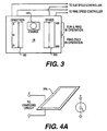
Figure 3 illustrates one example of a general arrangement for the structure and operation of the user control panel according to the present invention; -
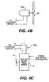
Figures 4A - 4C illustrate examples of individual electrical energy generating sources and their accompanying structural connections to the charging circuit applicable to the preferred embodiment of the present invention; -
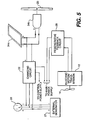
Figure 5 shows one example of a general system block diagram for implementing the use of several electrical energy generating sources together connected to the charging circuit of the preferred embodiment of the present invention; -
Figure 6 shows a second example of a general system block diagram for implementing the use of several electrical energy generating sources together connected to an energy input and load management circuit applicable to the preferred embodiment of the present invention; -
Figure 7 shows a system block diagram of the circuit components of one embodiment for the charging circuit; and -
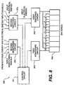
Figure 8 illustrates a general system block diagram of the components implementing the energy input and load management circuit applicable to the circuit ofFigure 6 . - With reference to the figures, like reference characters will be used to indicate like elements throughout the several embodiments and views thereof. In particular, with reference to
Figure 1 , thepropulsion system 10 of the present invention is generally embodied in a variable speed electric motor/transmission 12 connected through a shaft to apropeller 14. The motor/transmission 12 is a dual-input, infinite-speed electrically powered motor/transmission device. - As explained in
U.S. Patent No. 5,067,932 , an electric motor/transmission, as applicable to the present invention, includes a sun gear motor powering a sun gear assembly, a ring gear motor powering a ring gear assembly and a transmission assembly. The ring gear assembly can be rotated in a forward or reverse direction at an infinite number of speeds. To alter the amount of torque delivered by the motor/transmission, the sun gear assembly may be rotated in a forward direction, a reverse direction or may be locked in a stationary position. - In operation, the electric motor/
transmission 12 drives thepropeller 14, thereby propelling the vessel (not shown) in which the system is installed. The direct connection from the electric motor/transmission 12 to the propeller allows substantially all of the torque developed by motor/transmission 12 to be transmitted directly topropeller 14. - The electric motor/
transmission 12 is further connected to aspeed control circuit 16 that varies the electrical power to the electric motor/transmission 12, thereby varying the speed of the electric motor/transmission 12 and thepropeller 14. Consequently, varying the speed of the propeller varies the speed of the vessel. Thespeed control circuit 16 is connected to auser control panel 18. From theuser control panel 18, the speed of the vessel or the amount of power to apply to thepropulsion system 10, along with the direction of rotation of thepropeller 14 to effect either forward or reverse motion can be selected. - The
speed control circuit 16 controls the amount of electric power inputted to the electric motor/transmission 12 from thepower supply circuit 20. Since a preferred embodiment of the present invention is primarily directed to be an auxiliary propulsion system for a sail-powered marine vessel, one conventional implementation of thepower supply circuit 20 is a bank of batteries, such as car batteries. However, other types of high capacity electric storage cells may be used for thepower supply circuit 20. For example, commercial versions of the battery cells used in modem diesel submarines may be applicable. - The
speed control circuit 16 can be implemented using a conventional microprocessor-based control circuit (not shown) as known in the art, wherein user inputs (i.e., pushing of a button, shifting of a lever, rotating of a dial) into theuser control panel 18 are translated into control signals. The control signals are then inputted into thespeed control circuit 16. The control signals are then interpreted by the microprocessor-based circuit of thespeed control circuit 16 to control the amount of electric power to be fed to the electric motor/transmission 12. - The
power supply 20 is replenished with electrical energy through a chargingcircuit 22. The chargingcircuit 22 controls and regulates the voltage and current levels inputted into the system for recharging thepower supply 20. In an embodiment of the invention where thepower supply 20 consists of a bank of batteries, the chargingcircuit 22 as shown inFigure 7 can includemonitoring circuitry 22a for monitoring and signalling which batteries in a bank ofbatteries 20a need replenishment or replacement. Also, the chargingcircuit 22 can include switchingcircuitry 22b for selectively charging the batteries; in order to either evenly regulate the charging of the batteries or to charge only the batteries that require charging. A chargingcontrol circuit 22c is connected to receive and process signal data from themonitoring circuitry 22a and to control the switching and charging operation of the switchingcircuitry 22b. - The charging
circuit 22 is further connected to at least one electricalenergy input source 24 and anexternal energy source 26. Theelectrical input source 24 is embodied in an electrical energy generating device or system that can generate electrical energy with which to charge thepower supply 20 while the boat/vessel is moving under sail or even while it is stationary away from the docks. In the preferred embodiment of the invention, such electrical energy generating devices include, as shown inFigures 4A through 4C , solar panels composed of an array of photoelectric cells (Figure 4A ), wind-powered generators (Figure 4B ), and water- or wave-powered generators (Figure 4C ). As shown inFigure 4B , one example of a wind-powered generator is a windmill-type device consisting of anelectrical generator 24b with apropeller 25 that rotates with the wind. - In the preferred embodiment of the present invention, the water- or wave-powered generator incorporates the electric motor/
transmission 12 that is coupled to aregenerative feedback circuit 24c and its accompanying circuitry (not shown). This wave-powered generator operates while the boat/vessel is moving under sail. As the boat/vessel moves, the movement of the boat/vessel through the water forces water passing underneath the boat or vessel to move through thepropeller 14 that is idle when the electric motor/transmission 12 is not operating. The direct connection between the propeller and the electric motor/transmission 12 causes the movement of the water to rotate thepropeller 14 and the electric motor/transmission 12, thereby operating the electric motor/transmission 12 as an electric generator, opposite its normal operation as an electric motor. As will be further explained and illustrated hereinafter, the electrical energy generated by the electric motor/transmission 12 is fed through theregenerative feedback loop 24c to thepower supply 20. - The
external energy source 26 may be embodied by any conventional power supply or generator system external to thepower supply 20 and the various types of electric input sources 24. For example, one type of external energy source is the conventional 115-volt heavy-duty outlet available at typical docks and ports. Another example is the conventional gasoline-powered generator which can either be located at a dock or be carried on the boat/vessel. - In a more detailed embodiment of the present invention, as illustrated in
Figure 2 , thespeed control circuit 16 is embodied in asun speed controller 116 and aring speed controller 117. The operation of each of these controllers is determined by the inputs generated through theuser control panel 18. As noted above, the electric motor/transmission 12 includes a sun gear motor powering a sun gear assembly; a ring gear motor powering a ring gear assembly; and a transmission assembly (all not shown). Thesun speed controller 116 controls the electrical energy fed to the sun gear motor, thereby controlling the speed and torque of the sun gear motor and its corresponding sun gear assembly. Thering speed controller 117, on the other hand, controls the electrical energy fed to the ring gear motor, thereby controlling the speed and torque of the ring gear motor and its corresponding ring gear and transmission assemblies. - The
power supply 20 is embodied in amain power supply 120 that supplies the electrical energy for operating the sun and ring gear motors of the electric motor/transmission, and acontrol power supply 121 that powers the sun andring gear controllers - The charging
circuit 22 is configured to receive and regulate electrical energy from not only theelectrical input source 24, but also from a conventional 115 volt heavy-duty outlet 126 and an external generator 127 (i.e., a gasoline-powered generator). Further, the chargingcircuit 22 regulates the electrical energy inputted into each of the main and controlpower supplies - In a separate circuit, the electric motor/
transmission 12 is connected to themain power supply 120 through aregenerative feedback circuit 28 that includes theregenerative feedback loop 24c shown inFigure 4C . Theregenerative feedback circuit 28 receives electrical energy from the electric motor/transmission 12 when it operates as a generator (as explained above), and feeds that energy to recharge themain power supply 120 directly. - Like the charging
circuit 22 shown inFigure 7 , theregenerative feedback circuit 28 in one embodiment (not shown) can incorporate monitoring circuitry for monitoring and signalling which batteries in a bank of batteries need replenishment or replacement, and switching circuitry for selectively charging the batteries, in order to either evenly regulate the charging of the batteries or to charge only the batteries that require charging. - As shown in
Figure 3 , one embodiment for theuser control panel 18, in accordance with the system of the present invention shown inFigure 2 , comprises anENABLE switch 181, adirection control device 182, and aspeed control device 183. The physical implementation of all three devices would be embodied in the use of switches and variable input level devices as known in the art. For example,ENABLE switch 181 may be embodied in a conventional momentary contact switch, while thedirection control device 182 and thespeed control device 183 may be embodied in conventional variable position levers. Both thedirection control device 182 and thespeed control device 183 are connected to send corresponding control signals to thesun speed controller 116 and to thering speed controller 117. - In the functional implementation of the invention as shown in
Figure 2 , theENABLE switch 181 controls activation of theuser control panel 18, for example, by controlling the connection to thecontrol power supply 121. When theuser control panel 18 is active, thedirection control device 182 outputs direction control signals to both thesun speed controller 116 and thering speed controller 117 determining whether the electric motor/transmission 12 will operate and propel the boat/vessel in a forward (setting F) or reverse (setting R) direction, or remain in an idle or neutral (setting N) state. - The
speed control device 183 outputs speed control signals to thesun speed controller 116 and thering speed controller 117, determining the speed and torque output levels of the sun gear motor and the ring gear motor. As illustrated inFigure 3 , thespeed control device 183 is structured to vary between maximum (setting MAX) and minimum (setting MIN) output levels of the motors, and to output speed control signals corresponding to a selected output level. One technique for implementing thespeed control device 183, as well as thedirection control device 182, involves the use of a microprocessor-controlled circuit (not shown) as known in the art. The positions of the two control devices are translated by the microprocessor-controlled circuit into the corresponding direction and speed control signals. Those direction and speed control signals are then inputted into thesun speed controller 116 and thering speed controller 117. Thesun speed controller 116 and thering speed controller 117 in turn use the control signals to regulate the electric energy fed to the electric motor/transmission 12. - An alternative technique for implementing the direction and
speed control devices sun speed controller 116 and thering speed controller 117. In this implementation, both thesun speed controller 116 and thering speed controller 117 are implemented using microprocessor-controlled circuits (not shown). Thesun speed controller 116 and thering speed controller 117 translate the outputted signals from theuser control panel 18, and respectively regulate the operation of the electric motor/transmission 12. - A further alternative technique for implementing the direction and
speed control devices user control panel 18, as well as the sun speed andring speed controllers user control panel 18 and in each of the sun speed andring speed controllers - In operation, to move the boat/vessel forward, for example, the
direction control device 182 is set in the "forward" position (setting F) whilespeed control device 183 is positioned at a relatively low setting (i.e., at or near setting MIN). In this configuration, the direction control device signals thesun speed controller 116 to configure the electric motor/transmission 12 with the sun gear assembly locked rigidly in place, while allowing the ring gear assembly to be rotated in the desired direction to propel the boat/vessel forward. - Simultaneously, the
speed control device 183 communicates with thering speed controller 117 to direct the electric motor/transmission 12 to rotate the ring gear assembly at a relatively slow rotational velocity. In this manner,motor transmission 12 delivers a minimum amount of torque to thepropeller 14, thereby rotating thepropeller 14 at a relatively slow rotational velocity. - To propel the boat/vessel at higher velocities, the
propeller 14 must be rotated at a higher rotational velocity and the electric motor/transmission 12 must produce a greater amount of torque. To do so,speed control device 183 is set at or near a midway point between the maximum output (setting MAX) and minimum output or idle settings (setting MIN), thereby directing thesun speed controller 116 to rotate the sun gear assembly in a direction identical to the ring gear assembly's direction. The sun gear assembly rotates at a rotational velocity less than ring gear assembly's rotational speed when thespeed control device 183 is positioned between the midway position and the maximum output setting (MAX). As a result, the electric motor/transmission 12 produces more torque than when the sun gear assembly is rigidly fixed, thereby propelling the boat/vessel faster. - The boat/vessel is propelled forward at a maximum speed when the electric motor/
transmission 12 delivers a maximum amount of torque to thepropeller 14. Maximum torque is produced when thespeed control device 183 is positioned at the maximum setting (MAX). At that setting, thespeed control device 183 directs thesun speed controller 116 to rotate the sun gear assembly in the same direction and at the same rotational velocity as the ring gear assembly. - To propel the boat/vessel in the reverse direction, the
direction control device 182 is positioned in the reverse setting (R). Thesun speed controller 116 and thering speed controller 117 direct the electric motor/transmission 12 to rotate the sun gear assembly and ring gear assembly in directions opposite to those discussed above. The speed of the boat's/vessel's rearward movement is controlled in the same fashion as that discussed above. - Further, the
direction control device 182 can be set at the "neutral" position (setting N) at whichpropeller 14 is not being rotated in either direction by the sun gear motor or the ring gear motor. In this position, sun gear motor and ring gear motor remain coupled with thepropeller 14, whereby rotation of thepropeller 14 due to the movement of the water will operate the electric motor/transmission as a generator. Consequently, electric energy generated by the electric motor/transmission 12 will be fed through theregenerative feedback circuit 28 to recharge the main power supply. - As shown in
Figure 5 , the electrical input source 24 (SeeFigures 1 and2 ) can be embodied in more than a single type of electrical energy generating system. Here, for example, theelectrical input source 24 consists of asolar panel 24a connected and operating in parallel with a wind-poweredgenerator 24b. Also, a regenerative feedback circuit embodying a water- or wave-poweredgenerator 24c can be included. In accordance with the embodiment illustrated inFigure 2 , theregenerative feedback circuit 28 is connected directly to themain power supply 120, since theregenerative feedback circuit 28 can include, as noted above, monitoring circuitry for monitoring and signalling which batteries in a bank of batteries need replenishment or replacement, and switching circuitry for selectively charging the batteries. When the chargingcircuit 22 and theregenerative feedback circuit 28 are designed as independent circuits, as illustrated inFigure 5 , a manual switching circuit (not shown) can be incorporated that allows a user to select which of the two circuits will regenerate themain power supply 120. - Alternatively, a system as shown in
Figure 6 may be used where an energy input andload management circuit 200 is used to control the regenerating of themain power supply 120 and thecontrol power supply 121. In essence, theload management circuit 200 incorporates the functions of the chargingcircuit 22 and the regenerative feedback circuit together. - As shown in
Figure 8 , one embodiment of theload management circuit 200 includes acontrol circuit 201, afirst monitoring circuit 202 for monitoring and signalling which batteries in a bank ofbatteries 20a need replenishment or replacement, afirst switching circuit 203 for selectively charging the batteries, asecond monitoring circuit 204 for monitoring which of the energy input devices is inputting or is capable of inputting energy, and asecond switching circuit 205 for switching between energy input devices. Thecontrol circuit 201 is a microprocessor-based device that controls the operation of the other circuits. - In operation, the
first monitoring circuit 202 monitors which batteries in a bank of batteries need replenishment or replacement, and signals thecontrol circuit 201 accordingly. Thesecond monitoring circuit 204 monitors which of the energy input devices can provide energy. For example, thesecond monitoring circuit 204 detects which of thesolar panel 24a (i.e., if there is available sunlight), the wind-poweredgenerator 24b (i.e., sufficiently strong air currents are rotating the windmill-type device 25), or the electric motor/transmission 12 (i.e., when the electric motor/transmission 12 is not being used as a motor) is generating electrical energy. Thesecond monitoring circuit 204 can also detect whether the system is connected to an external energy source (i.e., a 115-volt outlet at a dock), or to anexternal generator 27. Thesecond monitoring circuit 204 then signals thecontrol circuit 201 as to which energy input devices and other energy sources are available. - The
first switching circuit 203 is controlled by thecontrol circuit 201 and selectively switches between the energy storage cells in the main and controlpower supplies first switching circuit 203 selectively connects with the batteries that need recharging. In one variation of the energy input andload management circuit 200, thefirst monitoring circuit 202 measures the energy levels of the individual batteries, and thecontrol circuit 201 uses those measurements to determine the order and priority for recharging or to determine and thereby indicate which of the batteries needs replacement. - The
second switching circuit 205 is also controlled by thecontrol circuit 201 and selectively switches between the different energy input devices and energy sources as they become available, get connected or disconnected or diminish in providing energy. For example, while the boat/vessel is anchored offshore, the energy input andload management circuit 200 can be recharging the power supplies 120, 121. If sunlight is available, thesolar panel 24a automatically generates electricity. Thesecond monitoring circuit 204 detects the presence of electrical energy, and thesecond switching circuit 205, under control of thecontrol circuit 201, routes the energy accordingly to thefirst switching circuit 203 to recharge the power supplies 120, 121. If cloud cover develops, thereby diminishing the sunlight, but the offshore winds start to pick up, thesecond monitoring 204 detects the changes in the energy input devices. Thecontrol circuit 201 then controls thesecond switching circuit 205 to switch routing energy from thesolar panel 24a to routing energy from the wind-poweredgenerator 24b. - As a consequence, the energy input and
load management circuit 200 maximizes the usage of the different energy input devices and maintains the power supplies 120, 121 at optimum operational levels. - Although the present invention has been fully described in connection with the preferred embodiment thereof with reference to the accompanying drawings, it is to be noted that various changes and modifications are apparent to those skilled in the art. For example, the auxiliary propulsion system of the present invention can be used as the primary propulsion system for a boat, ship or vessel with little or no modification from the embodiments disclosed above. In addition, instead of a
conventional propeller 14, the electric motor/transmission can be connected to a turbine, a paddlewheel or other similar device that can provide locomotion through water, while being usable as a generator when water is forced to flow through it. These and other changes and modifications are to be understood as included within the scope of the present invention as defined by the appended claims, unless they depart therefrom.
Claims (13)
- An auxiliary propulsion system (10) for a boat or other marine vessel, comprising:a motor/transmission device (12) for generating locomotive force to propel said boat or vessel;an electrical power supply (20) for providing electrical energy to drive said motor/transmission device (12), said power supply (20) being operatively connected to said motor/transmission device (12);at least one electrical energy generating device (24) for generating electrical energy; anda charging circuit (22) operatively connected between said power supply (20) and said energy generating device (24), said charging circuit (22) having means for controlling charging of said power supply (20) with electrical energy from said energy generating device (24);characterized in that:the motor/transmission device is a dual input, infinite speed electrically powered motor/transmission device; and the system further comprises:a speed control circuit (16) electrically coupled to the dual input, infinite speed electrically powered motor/transmission device (12) to control the amount of power inputted to the dual input, infinite speed electrically powered motor/transmission device (12) andfurther characterized in that said at least one electrical energy generating device (24) for generating electrical energy comprises a regenerative feedback circuit (28) connected to said charging circuit (22) and to said dual input, infinite speed electrically powered motor/transmission device (12), said feedback circuit (28) including means for generating electrical energy from water motion through said dual input, infinite speed electrically powered motor/transmission device (12) when said dual input, infinite speed electrically powered motor/transmission device (12) is inactive in generating locomotive force.
- An auxiliary propulsion system (10) for a boat or other marine vessel according to claim 1, characterized in that said dual input, infinite speed electrically powered motor/transmission device (12) includes a water propulsion element (14) for propelling said boat or vessel.
- An auxiliary propulsion system (10) for a boat or other marine vessel according to claim 2. characterized in that said water propulsion element (14) for propelling said boat or vessel comprises a propeller (14).
- An auxiliary propulsion system (10) for a boat or other marine vessel according to claim 2. characterized in that said water propulsion element (14) for propelling said boat or vessel comprises a turbine.
- An auxiliary propulsion system (10) for a boat or other marine vessel according to claim 1. characterized in that said electrical power supply (20) comprises a first power supply (120) for supplying power to said dual input, infinite speed electrically powered motor/transmission device (12), and a second power supply (121) for supplying power to said dual input, infinite speed electrically powered motor/transmission device (12).
- An auxiliary propulsion system (10) for a boat or other marine vessel according to claim 5, characterized in that said electrical power supply (20) includes rechargeable electric storage cells (20a) for each of said first and second power supplies (120, 121).
- An auxiliary propulsion system (10) for a boat or other marine vessel according to claim 1, characterized in that said at least one electrical energy generating device (24) for generating electrical energy comprises solar panels (24a) of photoelectric cells connected to said charging circuit (22).
- An auxiliary propulsion system (10) for a boat or other marine vessel according to claim 1, characterized in that said at least one electrical energy generating device (24) for generating electrical energy comprises a wind-power generator (24b) connected to said charging circuit (22).
- An auxiliary propulsion system (10) for a boat or other marine vessel according to claim 8, characterized in that said wind-power generator (24b) includes a windmill type device (25).
- An auxiliary propulsion system (10) for a boat or other marine vessel according to claim 1, characterized in that said at least one electrical energy generating device (24) for generating electrical energy comprises solar panels of photoelectric cells (24a), a wind-power generator (24b) and a regenerative feedback circuit (28) all connected to said charging circuit (22), characterized in that said regenerative feedback circuit (28) is further connected to said dual input, infinite speed electrically powered motor/transmission device (12), and includes means for generating electrical energy from water motion through said dual input, infinite speed electrically powered motor/transmission device (12) when said dual input, infinite speed electrically powered motor/transmission device (12) is inactive in generating locomotive force.
- An auxiliary propulsion system (10) for a boat or other marine vessel according to claim 1 characterized in that said charging circuit (22) comprises an energy input and load management circuit (200) having a first monitoring circuit (202) connected to each of a plurality of rechargeable energy storage cells (20a) in said electrical power supply (20) for monitoring energy level statuses of each said plurality of energy storage cells (20a), a first switching circuit (203) connected to said plurality of energy storage cells (20a) end to said electrical energy generating and regenerating devices (24) for selectively charging said plurality of energy storage cells (20a), a second monitoring circuit (204) connected to said electrical energy generating devices (24) for monitoring which of said electrical energy generating or regenerating devices (24) is inputting or is capable of inputting electrical energy, a second switching circuit (205) connected to said electrical energy generating devices (24) for switching between said electrical energy generating devices (24), whereby a selected electrical energy generating or regenerating device (24) recharges selected energy storage cells (20a), and a control circuit (201) for controlling operation of said first and second monitoring circuits (202, 204) and said first and second switching circuits (203, 205).
- An auxiliary propulsion system (10) for a boat or other marine vessel according to claim 1, wherein the speed control circuit (16) includes two speed controllers (116, 117), each one of the speed controllers (116, 117) corresponding to an input of the dual input, infinite speed electrically powered motor/transmission device (12).
- An auxiliary propulsion system for a boat or other marine vessel according to claim 1, characterized in that said speed control circuit (16), includes a user control panel (18).
Applications Claiming Priority (3)
| Application Number | Priority Date | Filing Date | Title |
|---|---|---|---|
| US639436 | 1996-04-29 | ||
| US08/639,436 US5863228A (en) | 1996-04-29 | 1996-04-29 | Method and apparatus for propelling a marine vessel |
| PCT/US1997/007556 WO1997040999A1 (en) | 1996-04-29 | 1997-04-29 | Method and apparatus for propelling a marine vessel |
Publications (3)
| Publication Number | Publication Date |
|---|---|
| EP0896559A1 EP0896559A1 (en) | 1999-02-17 |
| EP0896559A4 EP0896559A4 (en) | 1999-06-09 |
| EP0896559B1 true EP0896559B1 (en) | 2009-12-16 |
Family
ID=24564077
Family Applications (1)
| Application Number | Title | Priority Date | Filing Date |
|---|---|---|---|
| EP97922660A Expired - Lifetime EP0896559B1 (en) | 1996-04-29 | 1997-04-29 | Method and apparatus for propelling a marine vessel |
Country Status (9)
| Country | Link |
|---|---|
| US (1) | US5863228A (en) |
| EP (1) | EP0896559B1 (en) |
| JP (1) | JP2000509346A (en) |
| KR (1) | KR20000065087A (en) |
| AT (1) | ATE452045T1 (en) |
| AU (1) | AU2827397A (en) |
| CA (1) | CA2253226A1 (en) |
| DE (2) | DE896559T1 (en) |
| WO (1) | WO1997040999A1 (en) |
Families Citing this family (39)
| Publication number | Priority date | Publication date | Assignee | Title |
|---|---|---|---|---|
| GB2340318A (en) * | 1998-08-04 | 2000-02-16 | Brian Ellis | Battery recharging station for electrically powered boats |
| DE19902012A1 (en) * | 1999-01-21 | 2000-08-03 | Mueller Hermann Frank | Sail for waterborne craft, with flexible solar cells attached to it and connected to energy store |
| ES2157857B1 (en) * | 1999-12-28 | 2003-02-16 | Alsina Francesc Sureda | INTERACTIVE AUTONOMOUS SYSTEM OF SOLAR ENERGY PRODUCTION. |
| JP4532659B2 (en) * | 2000-03-28 | 2010-08-25 | ヤンマー株式会社 | Ship propulsion device |
| JP3914001B2 (en) * | 2001-04-20 | 2007-05-16 | セイコーエプソン株式会社 | Power charging device from multi-energy source |
| US6659815B2 (en) * | 2001-06-11 | 2003-12-09 | Maruta Electric Boatworks Llc | Efficient motors and controls for watercraft |
| JP2003081191A (en) * | 2001-09-13 | 2003-03-19 | Yanmar Co Ltd | Ship power generation and propulsion systems |
| ES1050760Y (en) * | 2001-09-25 | 2002-09-16 | Moreu Fernando Correa | VEHICLE THAT FOR ITS MOVEMENT AND USE USES PHOTOVOLTAIC SOLAR ENERGY. |
| US6957990B2 (en) * | 2002-08-21 | 2005-10-25 | Lowe Jerry W | Electric houseboat |
| ES2220214B1 (en) * | 2003-05-21 | 2006-01-16 | Alberto Ruiz Luque | ENERGY GENERATOR FOR SAILING BOATS. |
| US6802749B1 (en) * | 2003-07-28 | 2004-10-12 | Ty E. Justus | Marine vessel trolling and battery recharging system |
| EP1651512A4 (en) * | 2003-07-31 | 2009-05-06 | Solar Sailor Pty Ltd | Unmanned ocean vehicle |
| US6962124B1 (en) * | 2004-02-17 | 2005-11-08 | Charles Dean North | Round boat |
| US20060208570A1 (en) | 2005-03-11 | 2006-09-21 | Solomon Technologies, Inc. | System and method for automating power generation, propulsion and use management |
| ITMI20051088A1 (en) * | 2005-06-10 | 2006-12-11 | Fb Design Srl | GROUP OF PROPULSION FOR MOTORIZED VESSELS AND CRAFTS MADE THAT MADE |
| US8244419B2 (en) * | 2006-10-24 | 2012-08-14 | Mi-Jack Canada, Inc. | Marine power train system and method of storing energy in a marine vehicle |
| US9118206B2 (en) * | 2006-11-16 | 2015-08-25 | Cummins Power Generation Ip, Inc. | Management of an electric power generation and storage system |
| EP2082955A1 (en) * | 2008-01-24 | 2009-07-29 | Jegel, Franz Peter, Ing. | Hybrid module for water vehicles |
| US20090222155A1 (en) * | 2008-02-15 | 2009-09-03 | Glacier Bay, Inc. | Propulsion system |
| US7918696B2 (en) * | 2008-07-14 | 2011-04-05 | General Electric Company | System and method for dynamic energy recovery in marine propulsion |
| FR2938234B1 (en) * | 2008-11-13 | 2010-11-26 | Stx France Cruise Sa | AUTOMOTIVE SHIP AFFECTED TO NAVIGATION ON A SET DISTANCE BETWEEN A STARTING POINT AND A POINT OF ARRIVAL |
| CA2643878A1 (en) * | 2008-11-14 | 2010-05-14 | Pierre Caouette | An electronic method of controlling propulsion & regeneration for electric, hybrid-electric and diesel-electric marine crafts |
| US8706330B2 (en) | 2008-11-14 | 2014-04-22 | Hybrid Innovation Technologies Llc | Electronic system and method of automating, controlling, and optimizing the operation of one or more energy storage units and a combined serial and parallel hybrid marine propulsion system |
| US8393926B2 (en) | 2009-02-12 | 2013-03-12 | Twin Disc, Inc. | Hybrid marine power train system |
| JP5124047B2 (en) * | 2009-04-15 | 2013-01-23 | 日本郵船株式会社 | Ship |
| US9061747B2 (en) * | 2009-07-01 | 2015-06-23 | Kendyl A. Roman | Clean energy powered surfboards |
| DE102010040920A1 (en) | 2010-09-16 | 2012-03-22 | Aloys Wobben | Ship, especially cargo ship, with a Magnus rotor |
| IT1403294B1 (en) * | 2010-12-28 | 2013-10-17 | Seagate S R L | METHOD AND ELECTRONIC SYSTEM FOR THE CONTROL OF THE PROPULSION MODES OF A BOAT |
| CN102815390B (en) * | 2012-09-06 | 2015-04-22 | 珠海云洲智能科技有限公司 | Portable intelligent propelling system |
| US20150027125A1 (en) * | 2013-07-24 | 2015-01-29 | Anil Raj | Process for harvesting, storing, and using renewable energy to propel and power boats and ships, and maximize their average speed |
| DK178218B1 (en) * | 2014-02-17 | 2015-08-31 | Bauritec I S | A method of operating a boat |
| CN104002689A (en) * | 2014-06-09 | 2014-08-27 | 赵尚庭 | Wind-solar complementary electric vehicle power system and control method thereof |
| TWI592335B (en) * | 2015-09-24 | 2017-07-21 | 財團法人船舶暨海洋產業研發中心 | Energy management method for boats and ships |
| KR101824590B1 (en) * | 2016-08-16 | 2018-02-01 | 삼성중공업 주식회사 | Auxillary thrust apparatus for ship |
| US10040531B1 (en) * | 2017-02-09 | 2018-08-07 | Hal Fidlow | Waterborne vessel braking system and method |
| US20190291840A1 (en) * | 2018-03-20 | 2019-09-26 | Shirley Street | Boat-Mounted Wind Power Assembly |
| WO2021081645A1 (en) | 2019-10-29 | 2021-05-06 | Glas Ocean Electric Inc. | System and method of hybrid marine propulsion |
| CN111232176B (en) * | 2020-03-24 | 2024-12-27 | 中国华能集团清洁能源技术研究院有限公司 | A ship auxiliary power device based on tidal energy |
| US12043359B2 (en) * | 2021-12-02 | 2024-07-23 | Brunswick Corporation | Marine propulsion and generator systems and methods |
Family Cites Families (13)
| Publication number | Priority date | Publication date | Assignee | Title |
|---|---|---|---|---|
| US1181988A (en) * | 1912-10-21 | 1916-05-09 | Edward N Breitung | Ship. |
| US3643438A (en) * | 1969-12-31 | 1972-02-22 | Charles R Barsby | Jet engines |
| US3703642A (en) * | 1971-10-28 | 1972-11-21 | Rodolfo Rodriguez Balaguer | Outboard motor unit |
| US3935833A (en) * | 1973-07-25 | 1976-02-03 | Sundstrand Corporation | Jet boat pump |
| US3977353A (en) * | 1974-07-31 | 1976-08-31 | James Toyama | Jet powered marine propulsion unit |
| US3918389A (en) * | 1974-11-26 | 1975-11-11 | Kiyoshi Shima | Marine steering and propulsion device |
| GB2075610B (en) * | 1980-05-07 | 1983-06-02 | Clarke Lionel Osborne | Converting wave motion to useful energy |
| US4553037A (en) * | 1982-11-26 | 1985-11-12 | Veazey Sidney E | Solar breeze power package and saucer ship |
| US4565529A (en) * | 1983-08-17 | 1986-01-21 | Aertker Walter P | Remotely controlled steering apparatus for outboard trolling motors |
| US4756698A (en) * | 1985-09-25 | 1988-07-12 | Gorg Timothy J | Jet system for sailboats and the like |
| US5067932A (en) * | 1990-11-28 | 1991-11-26 | Edwards Jonathan R | Dual-input infinite-speed integral motor and transmission device |
| US5131341A (en) * | 1990-12-03 | 1992-07-21 | Edwin Newman | Solar powered electric ship system |
| US5498950A (en) * | 1994-04-29 | 1996-03-12 | Delco Electronics Corp. | Battery monitoring, charging and balancing apparatus |
-
1996
- 1996-04-29 US US08/639,436 patent/US5863228A/en not_active Expired - Fee Related
-
1997
- 1997-04-29 CA CA002253226A patent/CA2253226A1/en not_active Abandoned
- 1997-04-29 DE DE0896559T patent/DE896559T1/en active Pending
- 1997-04-29 WO PCT/US1997/007556 patent/WO1997040999A1/en not_active Ceased
- 1997-04-29 AU AU28273/97A patent/AU2827397A/en not_active Abandoned
- 1997-04-29 EP EP97922660A patent/EP0896559B1/en not_active Expired - Lifetime
- 1997-04-29 JP JP9539268A patent/JP2000509346A/en active Pending
- 1997-04-29 DE DE69739704T patent/DE69739704D1/en not_active Expired - Fee Related
- 1997-04-29 KR KR1019980708674A patent/KR20000065087A/en not_active Withdrawn
- 1997-04-29 AT AT97922660T patent/ATE452045T1/en not_active IP Right Cessation
Also Published As
| Publication number | Publication date |
|---|---|
| US5863228A (en) | 1999-01-26 |
| EP0896559A4 (en) | 1999-06-09 |
| AU2827397A (en) | 1997-11-19 |
| KR20000065087A (en) | 2000-11-06 |
| EP0896559A1 (en) | 1999-02-17 |
| DE69739704D1 (en) | 2010-01-28 |
| WO1997040999A1 (en) | 1997-11-06 |
| JP2000509346A (en) | 2000-07-25 |
| DE896559T1 (en) | 1999-06-10 |
| ATE452045T1 (en) | 2010-01-15 |
| CA2253226A1 (en) | 1997-11-06 |
Similar Documents
| Publication | Publication Date | Title |
|---|---|---|
| US5863228A (en) | Method and apparatus for propelling a marine vessel | |
| ES2593471T3 (en) | Hybrid propulsion systems | |
| CN108069011B (en) | Marine drive and method for operating a marine drive | |
| WO2017135199A1 (en) | Ship power system | |
| US20130293003A1 (en) | Propulsion system | |
| EP2658773B1 (en) | Propulsion system | |
| AU2018413663B2 (en) | Remote control unmanned surface vehicle with wind-driven cycloidal propeller | |
| EP2722272A1 (en) | Hydrogen device for sailing boats | |
| JP2025109748A (en) | Marine power distribution system and ship | |
| JP2007284018A (en) | Marine hybrid propulsion system | |
| CN208007234U (en) | A kind of wind-force drives remote controlled unmanned ship with solar association | |
| CN219008093U (en) | Marine hybrid power system and ship | |
| US12515775B2 (en) | System and method of hybrid marine propulsion | |
| RU2855191C1 (en) | Vessel with rotary electric installation | |
| RU2859045C2 (en) | Wind-powered vessel | |
| CN121749416A (en) | Ship energy system and method based on resistance power generation and battery pack alternate power supply | |
| AU2008334928B2 (en) | Hybrid propulsion systems | |
| CN122009457A (en) | Marine parallel hybrid planetary gear driving device and control method | |
| KR20140075916A (en) | Parallel Driving System For Boat and Operating Method thereof |
Legal Events
| Date | Code | Title | Description |
|---|---|---|---|
| PUAI | Public reference made under article 153(3) epc to a published international application that has entered the european phase |
Free format text: ORIGINAL CODE: 0009012 |
|
| 17P | Request for examination filed |
Effective date: 19981028 |
|
| AK | Designated contracting states |
Kind code of ref document: A1 Designated state(s): AT BE CH DE DK ES FI FR GB GR IE IT LI NL |
|
| ITCL | It: translation for ep claims filed |
Representative=s name: BARZANO' E ZANARDO MILANO S.P.A. |
|
| EL | Fr: translation of claims filed | ||
| A4 | Supplementary search report drawn up and despatched |
Effective date: 19990428 |
|
| AK | Designated contracting states |
Kind code of ref document: A4 Designated state(s): AT BE CH DE DK ES FI FR GB GR IE IT LI NL |
|
| DET | De: translation of patent claims | ||
| RIC1 | Information provided on ipc code assigned before grant |
Free format text: 6B 60L 11/02 A, 6B 60L 8/00 B, 6B 63H 19/02 B |
|
| 17Q | First examination report despatched |
Effective date: 20051116 |
|
| GRAP | Despatch of communication of intention to grant a patent |
Free format text: ORIGINAL CODE: EPIDOSNIGR1 |
|
| GRAS | Grant fee paid |
Free format text: ORIGINAL CODE: EPIDOSNIGR3 |
|
| GRAA | (expected) grant |
Free format text: ORIGINAL CODE: 0009210 |
|
| AK | Designated contracting states |
Kind code of ref document: B1 Designated state(s): AT BE CH DE DK ES FI FR GB GR IE IT LI NL |
|
| REG | Reference to a national code |
Ref country code: GB Ref legal event code: FG4D |
|
| REG | Reference to a national code |
Ref country code: CH Ref legal event code: EP |
|
| REG | Reference to a national code |
Ref country code: IE Ref legal event code: FG4D |
|
| REF | Corresponds to: |
Ref document number: 69739704 Country of ref document: DE Date of ref document: 20100128 Kind code of ref document: P |
|
| REG | Reference to a national code |
Ref country code: NL Ref legal event code: VDEP Effective date: 20091216 |
|
| PG25 | Lapsed in a contracting state [announced via postgrant information from national office to epo] |
Ref country code: FI Free format text: LAPSE BECAUSE OF FAILURE TO SUBMIT A TRANSLATION OF THE DESCRIPTION OR TO PAY THE FEE WITHIN THE PRESCRIBED TIME-LIMIT Effective date: 20091216 |
|
| PG25 | Lapsed in a contracting state [announced via postgrant information from national office to epo] |
Ref country code: AT Free format text: LAPSE BECAUSE OF FAILURE TO SUBMIT A TRANSLATION OF THE DESCRIPTION OR TO PAY THE FEE WITHIN THE PRESCRIBED TIME-LIMIT Effective date: 20091216 |
|
| PG25 | Lapsed in a contracting state [announced via postgrant information from national office to epo] |
Ref country code: NL Free format text: LAPSE BECAUSE OF FAILURE TO SUBMIT A TRANSLATION OF THE DESCRIPTION OR TO PAY THE FEE WITHIN THE PRESCRIBED TIME-LIMIT Effective date: 20091216 Ref country code: ES Free format text: LAPSE BECAUSE OF FAILURE TO SUBMIT A TRANSLATION OF THE DESCRIPTION OR TO PAY THE FEE WITHIN THE PRESCRIBED TIME-LIMIT Effective date: 20100327 |
|
| PG25 | Lapsed in a contracting state [announced via postgrant information from national office to epo] |
Ref country code: BE Free format text: LAPSE BECAUSE OF FAILURE TO SUBMIT A TRANSLATION OF THE DESCRIPTION OR TO PAY THE FEE WITHIN THE PRESCRIBED TIME-LIMIT Effective date: 20091216 |
|
| PLBE | No opposition filed within time limit |
Free format text: ORIGINAL CODE: 0009261 |
|
| STAA | Information on the status of an ep patent application or granted ep patent |
Free format text: STATUS: NO OPPOSITION FILED WITHIN TIME LIMIT |
|
| PG25 | Lapsed in a contracting state [announced via postgrant information from national office to epo] |
Ref country code: GR Free format text: LAPSE BECAUSE OF FAILURE TO SUBMIT A TRANSLATION OF THE DESCRIPTION OR TO PAY THE FEE WITHIN THE PRESCRIBED TIME-LIMIT Effective date: 20100317 |
|
| 26N | No opposition filed |
Effective date: 20100917 |
|
| REG | Reference to a national code |
Ref country code: CH Ref legal event code: PL |
|
| GBPC | Gb: european patent ceased through non-payment of renewal fee |
Effective date: 20100429 |
|
| REG | Reference to a national code |
Ref country code: FR Ref legal event code: ST Effective date: 20101230 |
|
| PG25 | Lapsed in a contracting state [announced via postgrant information from national office to epo] |
Ref country code: IE Free format text: LAPSE BECAUSE OF NON-PAYMENT OF DUE FEES Effective date: 20100429 Ref country code: DK Free format text: LAPSE BECAUSE OF FAILURE TO SUBMIT A TRANSLATION OF THE DESCRIPTION OR TO PAY THE FEE WITHIN THE PRESCRIBED TIME-LIMIT Effective date: 20091216 |
|
| PG25 | Lapsed in a contracting state [announced via postgrant information from national office to epo] |
Ref country code: LI Free format text: LAPSE BECAUSE OF NON-PAYMENT OF DUE FEES Effective date: 20100430 Ref country code: DE Free format text: LAPSE BECAUSE OF NON-PAYMENT OF DUE FEES Effective date: 20101103 Ref country code: CH Free format text: LAPSE BECAUSE OF NON-PAYMENT OF DUE FEES Effective date: 20100430 |
|
| PG25 | Lapsed in a contracting state [announced via postgrant information from national office to epo] |
Ref country code: GB Free format text: LAPSE BECAUSE OF NON-PAYMENT OF DUE FEES Effective date: 20100429 Ref country code: IT Free format text: LAPSE BECAUSE OF FAILURE TO SUBMIT A TRANSLATION OF THE DESCRIPTION OR TO PAY THE FEE WITHIN THE PRESCRIBED TIME-LIMIT Effective date: 20091216 |
|
| PG25 | Lapsed in a contracting state [announced via postgrant information from national office to epo] |
Ref country code: FR Free format text: LAPSE BECAUSE OF NON-PAYMENT OF DUE FEES Effective date: 20100430 |