EP0896384A2 - Multi-band antenna suitable for use in a mobile radio device - Google Patents
Multi-band antenna suitable for use in a mobile radio device Download PDFInfo
- Publication number
- EP0896384A2 EP0896384A2 EP98114574A EP98114574A EP0896384A2 EP 0896384 A2 EP0896384 A2 EP 0896384A2 EP 98114574 A EP98114574 A EP 98114574A EP 98114574 A EP98114574 A EP 98114574A EP 0896384 A2 EP0896384 A2 EP 0896384A2
- Authority
- EP
- European Patent Office
- Prior art keywords
- antenna
- helical
- band
- resonance circuit
- small
- Prior art date
- Legal status (The legal status is an assumption and is not a legal conclusion. Google has not performed a legal analysis and makes no representation as to the accuracy of the status listed.)
- Granted
Links
- 230000005855 radiation Effects 0.000 claims abstract description 20
- 239000003990 capacitor Substances 0.000 claims description 9
- 238000005476 soldering Methods 0.000 claims description 8
- 229910052751 metal Inorganic materials 0.000 claims description 6
- 239000002184 metal Substances 0.000 claims description 6
- 229910045601 alloy Inorganic materials 0.000 claims description 5
- 239000000956 alloy Substances 0.000 claims description 5
- 229920001971 elastomer Polymers 0.000 claims description 5
- 239000000806 elastomer Substances 0.000 claims description 5
- 239000011810 insulating material Substances 0.000 claims description 5
- 238000000465 moulding Methods 0.000 claims description 5
- 229920000642 polymer Polymers 0.000 claims description 5
- 239000011347 resin Substances 0.000 claims description 5
- 229920005989 resin Polymers 0.000 claims description 5
- 230000008878 coupling Effects 0.000 claims description 4
- 238000010168 coupling process Methods 0.000 claims description 4
- 238000005859 coupling reaction Methods 0.000 claims description 4
- KHYBPSFKEHXSLX-UHFFFAOYSA-N iminotitanium Chemical compound [Ti]=N KHYBPSFKEHXSLX-UHFFFAOYSA-N 0.000 claims description 4
- 229910004337 Ti-Ni Inorganic materials 0.000 claims description 3
- 229910011209 Ti—Ni Inorganic materials 0.000 claims description 3
- 239000000463 material Substances 0.000 claims description 3
- 239000006185 dispersion Substances 0.000 description 24
- 238000004804 winding Methods 0.000 description 15
- 238000010586 diagram Methods 0.000 description 14
- 230000005540 biological transmission Effects 0.000 description 11
- 238000005530 etching Methods 0.000 description 7
- 239000011295 pitch Substances 0.000 description 6
- 239000004020 conductor Substances 0.000 description 5
- 238000004519 manufacturing process Methods 0.000 description 4
- JRPBQTZRNDNNOP-UHFFFAOYSA-N barium titanate Chemical compound [Ba+2].[Ba+2].[O-][Ti]([O-])([O-])[O-] JRPBQTZRNDNNOP-UHFFFAOYSA-N 0.000 description 2
- 229910002113 barium titanate Inorganic materials 0.000 description 2
- 238000000034 method Methods 0.000 description 2
- 230000035939 shock Effects 0.000 description 2
- 238000005549 size reduction Methods 0.000 description 2
- 239000000919 ceramic Substances 0.000 description 1
- 239000002131 composite material Substances 0.000 description 1
- 230000002950 deficient Effects 0.000 description 1
- 230000000694 effects Effects 0.000 description 1
- 239000011888 foil Substances 0.000 description 1
- 229910001000 nickel titanium Inorganic materials 0.000 description 1
- 230000000717 retained effect Effects 0.000 description 1
- 239000000758 substrate Substances 0.000 description 1
Images







Classifications
-
- H—ELECTRICITY
- H01—ELECTRIC ELEMENTS
- H01Q—ANTENNAS, i.e. RADIO AERIALS
- H01Q11/00—Electrically-long antennas having dimensions more than twice the shortest operating wavelength and consisting of conductive active radiating elements
- H01Q11/02—Non-resonant antennas, e.g. travelling-wave antenna
- H01Q11/08—Helical antennas
-
- H—ELECTRICITY
- H01—ELECTRIC ELEMENTS
- H01Q—ANTENNAS, i.e. RADIO AERIALS
- H01Q1/00—Details of, or arrangements associated with, antennas
- H01Q1/12—Supports; Mounting means
- H01Q1/22—Supports; Mounting means by structural association with other equipment or articles
- H01Q1/24—Supports; Mounting means by structural association with other equipment or articles with receiving set
- H01Q1/241—Supports; Mounting means by structural association with other equipment or articles with receiving set used in mobile communications, e.g. GSM
- H01Q1/242—Supports; Mounting means by structural association with other equipment or articles with receiving set used in mobile communications, e.g. GSM specially adapted for hand-held use
- H01Q1/243—Supports; Mounting means by structural association with other equipment or articles with receiving set used in mobile communications, e.g. GSM specially adapted for hand-held use with built-in antennas
- H01Q1/244—Supports; Mounting means by structural association with other equipment or articles with receiving set used in mobile communications, e.g. GSM specially adapted for hand-held use with built-in antennas extendable from a housing along a given path
-
- H—ELECTRICITY
- H01—ELECTRIC ELEMENTS
- H01Q—ANTENNAS, i.e. RADIO AERIALS
- H01Q1/00—Details of, or arrangements associated with, antennas
- H01Q1/36—Structural form of radiating elements, e.g. cone, spiral, umbrella; Particular materials used therewith
- H01Q1/362—Structural form of radiating elements, e.g. cone, spiral, umbrella; Particular materials used therewith for broadside radiating helical antennas
-
- H—ELECTRICITY
- H01—ELECTRIC ELEMENTS
- H01Q—ANTENNAS, i.e. RADIO AERIALS
- H01Q5/00—Arrangements for simultaneous operation of antennas on two or more different wavebands, e.g. dual-band or multi-band arrangements
- H01Q5/30—Arrangements for providing operation on different wavebands
- H01Q5/307—Individual or coupled radiating elements, each element being fed in an unspecified way
- H01Q5/314—Individual or coupled radiating elements, each element being fed in an unspecified way using frequency dependent circuits or components, e.g. trap circuits or capacitors
-
- H—ELECTRICITY
- H01—ELECTRIC ELEMENTS
- H01Q—ANTENNAS, i.e. RADIO AERIALS
- H01Q5/00—Arrangements for simultaneous operation of antennas on two or more different wavebands, e.g. dual-band or multi-band arrangements
- H01Q5/30—Arrangements for providing operation on different wavebands
- H01Q5/307—Individual or coupled radiating elements, each element being fed in an unspecified way
- H01Q5/314—Individual or coupled radiating elements, each element being fed in an unspecified way using frequency dependent circuits or components, e.g. trap circuits or capacitors
- H01Q5/321—Individual or coupled radiating elements, each element being fed in an unspecified way using frequency dependent circuits or components, e.g. trap circuits or capacitors within a radiating element or between connected radiating elements
-
- H—ELECTRICITY
- H01—ELECTRIC ELEMENTS
- H01Q—ANTENNAS, i.e. RADIO AERIALS
- H01Q5/00—Arrangements for simultaneous operation of antennas on two or more different wavebands, e.g. dual-band or multi-band arrangements
- H01Q5/30—Arrangements for providing operation on different wavebands
- H01Q5/307—Individual or coupled radiating elements, each element being fed in an unspecified way
- H01Q5/342—Individual or coupled radiating elements, each element being fed in an unspecified way for different propagation modes
- H01Q5/357—Individual or coupled radiating elements, each element being fed in an unspecified way for different propagation modes using a single feed point
Definitions
- the present invention relates to an antenna for use in a mobile radio device etc. and, in particular, to a multi-band antenna which can carry out transmission and reception at a plurality of mutually different frequency bands.
- the PDC system uses 800MHz and 1.5GHz bands, while the PHS system uses a 1.9GHz band.
- 800MHz and 1.9GHz bands are used in U.S.A.
- 900MHz and 1.8GHz bands are used in Europe.
- a radio device when a radio device is used at different frequency bands, a plurality of antennas are used.
- an FM/AM radio set can be cited.
- a trap antenna which is so arranged as to be used at different frequency bands.
- the trap antennas have been widely used in amateur radio devices as multi-band antennas.
- JP-A-5-121924 discloses a conventional trap antenna.
- the disclosed trap antenna comprises a linear antenna element and a trap circuit having a coil and a capacitor.
- the conventional trap antenna can not be said to be suitable for use in a portable terminal for the portable telephone system.
- a multi-band antenna comprising an antenna element having an LC parallel resonance circuit and a first and a second radiation element connected to opposite ends of the LC parallel resonance circuit, wherein the LC parallel resonance circuit is constituted by self-resonance of an inductor itself.
- a telescopic multi-band whip antenna comprising a small-size antenna and a whip antenna which is receivable in a radio device casing and expandable, wherein the small-size antenna is located outside the radio device casing, the whip antenna being slidable relative to the small-size antenna, each of the small-size antenna and the whip antenna both having multi-band characteristics so that the multi-band characteristics are obtained both upon putting back and expansion of the whip antenna.
- a multi-band helical antenna comprising a plurality of helical coils, at least one helical guide around which the plurality of helical coils are wound, and a conductive holder holding the at least one helical guide, wherein power is fed from the conductive holder to at least one of the plurality of helical coils so as to obtain a plurality of resonance frequencies.
- a multi-band helical antenna comprising a plurality of helical coils having the same diameter and the different numbers of turns, a helical guide around which the plurality of helical coils are wound, an insulating portion being a dielectric and provided on a surface of the helical guide to separate the plurality of helical coils from each other, and a conductive holder holding the helical guide, power being fed from the holder to one of the plurality of helical coils and further fed to the other helical coil through capacitive coupling so as to obtain a plurality of resonance frequencies.
- a telescopic whip antenna comprising a rod antenna which is receivable in a casing and expandable, and a small-size antenna provided at an upper portion of the rod antenna, wherein power is fed to the rod antenna upon expansion and to the small-size antenna upon putting back, the small-size antenna being substantially in the form of a board made of an insulating material and formed thereon with an electrode pattern and uses a resonance frequency based on a dielectric constant of the board and the electrode pattern.
- a multi-band antenna 10 according to the first preferred embodiment of the present invention will be described, wherein the multi-band antenna 10 corresponds to two allocated frequency bands, that is, 800MHz and 1.9GHz bands.
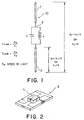
- the multi-band antenna 10 comprises a linear element 1 on an open end side as a first radiation element, a linear element 2 on a telephone side as a second radiation element, and a trap circuit connected therebetween.
- Each of the linear elements 1 and 2 is made of a superelastic alloy in the form of a Ti-Ni alloy.
- the trap circuit is achieved by self-resonance of an inductor.
- a chip laminated inductance element hereinafter referred to as "chip inductor" 3 is used as a surface mounting (SMD) type self-resonance inductor in Fig. 1.
- the chip inductor 3 is of a 1005 size (1.0mm x 0.5mm).
- the trap circuit is constituted by mounting only the chip inductor 3 on a substrate. Accordingly, the trap circuit can be obtained which does not require a capacitance element and is small in size, low in price and small in number of assembling steps.
- a length of each of the linear elements 1 and 2 may be ⁇ /2, ⁇ /4 or 3 ⁇ /8, while it is ⁇ /4 in an explanation given below.
- a length of the linear element 1 on the open end side was set to 3.9cm
- a length of the linear element 2 on the telephone side was set to 2.9cm
- each of the linear elements 1 and 2 had a diameter of 0.8mm and was made of the Ni-Ti alloy
- a value of the chip inductor 3 was set to 39nH
- a stray capacitance of the inductor was 0.18pF.
- a multi-band antenna 20 according to the second preferred embodiment of the present invention will be described.
- the linear element 1 on the open end side, being the first radiation element, in the multi-band antenna 10 shown in Fig. 1 is replaced with a helical element 11.
- the linear element 2 on the telephone side, being the second radiation element, in the multi-band antenna 10 is used as it is, and a chip inductor 3 having the same value as that in the multi-band antenna 10 is used for a trap circuit.
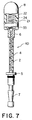
- the helical element 11 comprises a helical coil 16 and a helical guide 17 around which the helical coil 16 is wound.
- the chip inductor 3 is received in the helical coil guide 17 and has one end connected to one end of the helical coil 16.
- To the other end of the chip inductor 3 is connected one end of the linear element 2 being the second radiation element.
- a sleeve 6 made of a conductive material is provided around the linear element 2 at the foregoing one end thereof so as to reach the helical guide 17.
- the helical element 11 and one end of the sleeve 6 are covered through molding with flexible insulating resin such as polymer or elastomer so as to form a mold portion 8.
- a tube 4 made of a flexible insulating material such as polymer or elastomer is provided through molding to cover the linear element 2 from the other end of the sleeve 6 to the other end of the linear element 2.
- a holder 5 for attachment to a portable telephone (not shown) is mounted on the tube 4 so as to be slidable along an axis of the linear element 2.
- the holder 5 is provided near the other end of the linear element 2, and the other end of the linear element 2 is terminated by a stopper 7.
- the helical element 11 has an outer diameter of 2.8mm and a length of 18mm, and the helical coil 16 is made of a wire having a diameter of 0.4mm and has four turns.
- the multi-band antenna 20 in this embodiment achieves a multi-band characteristic similar to that of the multi-band antenna 10 shown in Fig. 1.
- the multi-band antenna 30 has, at a portion of a helical element 11 being a first radiation element, an inductor portion 23 in the form of an air-core coil having self-resonance, so as to form an LC parallel trap circuit by the self-resonance.
- the other structures are the same as those of the multi-band antenna 20 shown in Fig. 4.
- a linear element 2 on the telephone side has the same shape as that of the linear element 2 shown in Fig. 1.
- the helical element 11 comprises an integral coil having the inductor portion 23 of the trap circuit and a helical coil 16. With this arrangement, a multi-band characteristic similar to that of the multi-band antenna 10 shown in Fig. 1 was obtained.
- the inductor portion 23 is in the form of a coil having a length of 5mm, which is obtained by winding a wire having a diameter of 0.45mm so as to have an inner diameter of 2mm and six turns.
- the helical coil 16 is in the form of a coil having a length of 13mm, which is obtained by winding a wire having a diameter of 0.45mm so as to have an inner diameter of 2mm and ten turns.
- the multi-band antenna 40 is provided with a meander pattern element 21 having, at a portion of a printed board 24 formed with a meander pattern 22, an inductor portion 33 having self-resonance, so as to form an LC parallel trap circuit by the self-resonance.
- a linear element 2 on the telephone side is in the form of a Ti-Ni superelastic wire having a diameter of 0.8mm and a length of 31mm.
- the meander pattern element 21 is formed by using a helical element having a pattern width of 0.5mm, 24 turns, a coil width of 4mm and a whole coil length of 24mm. With this arrangement, the multi-band antenna 40 shown in Fig. 7 achieved a multi-band characteristic similar to that of the multi-band antenna 10 shown in Fig. 1.
- the LC parallel resonance circuit is formed by the self-resonance of the inductor itself.
- a resonance circuit using self-resonance of an inductor has basically one inductance element, and a capacitance is formed by a distributed capacitance of a coil.
- the number of components can be made small.
- the capacitance formed by the distributed capacitance is small as a constant so that the resonance circuit is constituted by inductance-leading LC resonance (for example, not less than 7nH and not greater than 1pF at 1.9GHz, not less than 8nH and not greater than 1pF at 1.8GHz), a band width at each frequency can be set large (for example, not greater than VSWR2.2). Therefore, the multi-band antenna with less number of components, with less number of manufacturing processes/steps and with excellent productivity can be provided at a low price.
- the foregoing multi-band antenna when used as an antenna for carrying out transmission and reception at a plurality of mutually different frequency bands, such as 800MHz and 1.9GHz, it can largely contribute to reduction in size of a multi-band portable radio device etc.
- the telescopic multi-band whip antenna comprises a whip antenna 41 and a small-size antenna 42.
- the whip antenna 41 is in the form of a combination of an insulating portion 45 and an LC parallel resonance circuit 43 including a chip inductor and a chip capacitor.
- the small-size antenna 42 is a small-size multi-band antenna which constituted by combining a helical coil antenna provided on a casing of the radio device and the LC parallel resonance circuit 43 and further by putting a cap 44 thereon.
- the whip antenna 41 is slidable in the small-size antenna 42.
- Fig. 9A is a diagram showing the multi-band antenna upon expansion thereof, wherein a stopper 46 is coupled to a holder 49 for retaining it.
- the holder 49 is used for fixing the small-size antenna 42 to the casing of the radio device.
- the stopper 46 is formed at its tip portion with a conductive portion 48 and an insulating portion 47.
- the insulating portion 47 is mechanically retained by the holder 49 upon expansion of the multi-band antenna so that the whip antenna 41 and the small-size antenna 42 are electrically separated.
- the conductive portion 48 is connected to a circuit within the casing of the radio device via a matching circuit.
- Fig. 9B is a diagram showing the multi-band antenna upon putting back the multi-band antenna, wherein the holder 49 for fixing the small-size antenna 42 to the casing of the radio device is coupled to the insulating portion 45 of the whip antenna 41. In this event, the holder 49 is connected to the circuit within the casing of the radio device via the matching circuit.
- a similar telescopic multi-band whip antenna can also be realized by using self-resonance of a chip inductor or an air-core coil, or a dielectric resonator having a size of 2mm x 2mm to 3mm x 3mm and made of a barium titanate material having a dielectric constant not less than 20. Further, a similar multi-band whip antenna can also be realized by using a circuit connected by using self-resonance of a chip inductor or an air-core coil.
- FIGs. 10A and 10B are diagrams showing the telescopic multi-band whip antenna upon expansion and upon putting back, respectively.
- the same or like elements are represented by the same reference signs so as to omit explanation thereof.
- a small-size antenna 52 has a flexible board formed thereon with a meander line pattern 59, and further provided thereon with an LC parallel resonance circuit 53 comprising a chip inductor and a chip capacitor, so as to accomplish a multi-band characteristic.
- LC parallel resonance circuit 53 comprising a chip inductor and a chip capacitor, so as to accomplish a multi-band characteristic.
- a similar telescopic multi-band whip antenna can also be realized using self-resonance of a chip inductor or an air-core coil.
- FIGs. 11A and 11B are diagrams showing the telescopic multi-band whip antenna upon expansion and upon putting back, respectively.
- the same or like elements are represented by the same reference signs so as to omit explanation thereof.
- a small-size antenna 62 is not provided with the LC parallel resonance circuit, and thus realizes a multi-band characteristic only by a meander pattern 69 formed on a flexible board.
- the electric characteristics of the small-size antenna and the whip antenna are both set to be the multi-band characteristics so that the multi-band characteristics can be obtained both upon expansion and putting back.
- the foregoing multi-band antenna is used as an antenna for carrying out transmission and reception at a plurality of mutually different frequency bands, such as 800MHz and 1.9GHz, it can largely contribute to reduction in size of a multi-band portable radio device etc.
- a multi-band helical antenna as a multi-band antenna according to the eighth preferred embodiment of the present invention will be described.
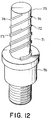
- a helical antenna 72 is formed by winding a helical coil 74 around a helical guide with five turns, while a helical antenna 73 is formed by winding a helical coil 74 around the helical guide 75 with three turns.
- the respective helical coils 74, 74 are in close contact with or soldered to a conductive holder 76 at their first turns so as to be fed with power parallelly.
- the holder 76 holds the helical guide 75.
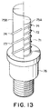
- FIG. 13 shows the state wherein a right-side half of a helical antenna 73 is removed.
- a helical antenna 72 is formed by winding a helical coil 74 around a small-diameter helical guide 75A with five turns.
- the helical antenna 73 is formed by winding a helical coil 74 around a large-diameter hollow helical guide 75B with three turns.
- the helical guides 75A and 75B are arranged concentrically and overlapped with each other.
- the respective helical coils 74, 74 are in close contact with or soldered to a conductive holder 76 at their first turns so as to be fed with power parallelly.
- the holder 76 holds the helical guides 75A and 75B.
- band widths of the two resonance frequencies can be adjusted so that desired band widths can be achieved.
- the helical coils 74, 74 are connected in series, and only one of the helical coils is fed with power.
- a multi-band helical antenna as a multi-band antenna according to the tenth preferred embodiment of the present invention will be described.
- a helical antenna 72 is formed by winding a helical coil 74 around a helical guide 75 with three turns.
- a helical antenna 73 is formed by winding a helical coil 74 around the helical guide 75 with two turns.
- the helical antennas 72 and 73 are connected in series by a serially connecting portion 77.
- the helical coil 74 of the helical antenna 72 is in close contact with or soldered to a conductive holder 76 at its first turn so as to be fed with power.
- the holder 76 holds the helical guide 75.
- a multi-band helical antenna as a multi-band antenna according to the eleventh preferred embodiment of the present invention will be described.
- a helical antenna 72 is formed by winding a helical coil 74 around a helical guide 75 with three turns.
- a helical antenna 73 is formed by winding a helical coil 74 around the helical guide 75 with two turns.
- the helical antennas 72 and 73 are separated from each other by a helical insulating portion 78, being a dielectric, provided on the surface or circumference of the helical guide 75.
- the helical coil 74 of the helical antenna 72 is in close contact with or soldered to a conductive holder 76 at its first turn so as to be fed with power.
- the holder 76 holds the helical guide 75.
- the helical antenna 73 is fed with power through capacitive coupling to the helical antenna 72.
- the multi-band characteristic is obtained by using a plurality of helical coils.
- the foregoing multi-band antenna is used as an antenna for carrying out transmission and reception at a plurality of mutually different frequency bands, such as 800MHz and 1.9GHz, it can largely contribute to reduction in size of a multi-band portable radio device etc.
- a telescopic whip antenna as a multi-band antenna according to the twelfth preferred embodiment of the present invention will be described.
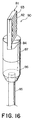
- a sleeve 87 working as a feed point is formed with a groove 84 into which an antenna member 81 in the form of a printed board 82 formed thereon with an electrode pattern 83 is fitted, and a connecting portion 88 connected to one end of a meander line pattern electrode (hereinafter referred to as "meander pattern") 83a is electrically and fixedly connected, by soldering or under pressure, to the conductive sleeve 87 coupled to a coupling portion 86, made of insulating resin, provided at one end of a rod antenna 85, so as to constitute a small-size antenna 90.
- meander line pattern electrode hereinafter referred to as "meander pattern”
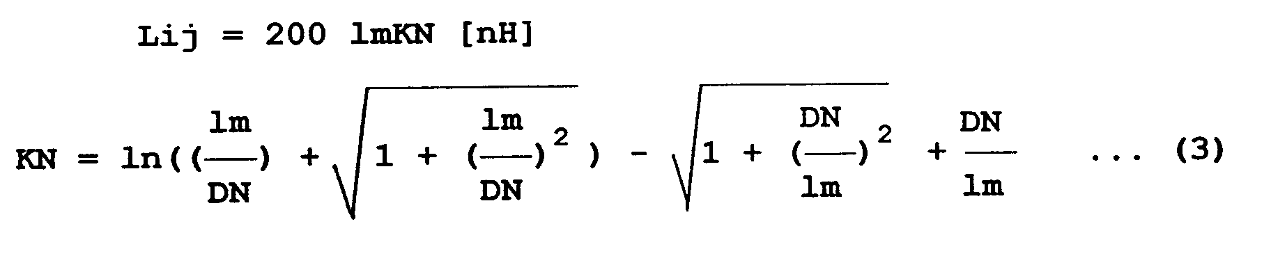
- S represents a sectional area (cm 2 ), N the number of turns, l a mean magnetic circuit length (cm) and k a Nagaoke coefficient.
- Resonance frequencies are each derived by the following equation (5) using a line capacitance C and the inductance L derived above:
- a helical coil In case of a helical coil, it is fixed to a helical guide provided with grooves at constant pitches so as to avoid dispersion in line capacitance C.
- the meander pattern 83a is formed by etching the printed board 82.
- a pattern width can be achieved with an accuracy of ⁇ 20 ⁇ m error. Therefore, the line capacitance can be constant without using the member for uniforming the pitches as required in the helical coil so that the dispersion in resonance frequency can be suppressed. Reduction in weight of the small-size antenna can also be achieved. Further, since the antenna member 81 is only fitted into the groove 84 of the sleeve 87 upon assembling, the productivity is high. Moreover, since the feed point is determined by fixing the printed board 82, the dispersion in resonance frequency due to dispersion in feed point can also be suppressed.
- a telescopic whip antenna as a multi-band antenna according to the thirteenth preferred embodiment of the present invention will be described.
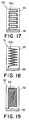
- a sleeve 87 working as a feed point is formed with a groove 84, and an antenna member 91 in the form of a printed board 82 formed thereon with a sawtooth line pattern or a jagged line pattern (hereinafter collectively referred to as "sawtooth pattern") 83b as an electrode pattern 83 is fitted into the groove 84 and fixed thereto by soldering or under pressure so as to constitute a small-size antenna.
- An actual product has a cap (not shown) for antenna protection.
- the sawtooth pattern 83b is formed by etching the printed board.
- a pattern width can be achieved with an accuracy of ⁇ 20 ⁇ m error. Therefore, the line capacitance can be constant without using the member for uniforming the pitches as required in the helical coil so that the dispersion in resonance frequency can be suppressed. Reduction in weight of the small-size antenna can also be achieved.
- the productivity is high.
- the feed point is determined by fixing the printed board 82, the dispersion in resonance frequency due to dispersion in feed point can also be suppressed.
- a telescopic whip antenna as a multi-band antenna according to the fourteenth preferred embodiment of the present invention will be described.
- a sleeve 87 working as a feed point is formed with a groove 84, and an antenna member 92 in the form of a printed board 82 formed thereon with a spiral pattern 83c as an electrode pattern 83 is fitted into the groove 84 and fixed thereto by soldering or under pressure so as to constitute a small-size antenna.
- An actual product has a cap (not shown) for antenna protection.
- S represents a sectional area (cm 2 ), N the number of turns, l a mean magnetic circuit length (cm) and k a Nagaoke coefficient.
- l represents a conductor radius (cm)
- n the number of turns
- Di a spiral inner diameter (inch)
- Do a spiral outer diameter (inch).
- Resonance frequencies are each derived by the following equation (8) using a line capacitance C and the inductance L derived above:
- the spiral pattern 83c is formed by etching the printed board 82.
- a pattern width can be achieved with an accuracy of ⁇ 20 ⁇ m error. Therefore, the line capacitance C can be constant without using the member for uniforming the pitches as required in the helical coil so that the dispersion in resonance frequency can be suppressed. Reduction in weight of the small-size antenna can also be achieved. Further, since the antenna member 92 is only fitted into the groove 84 of the sleeve 87 upon assembling, the productivity is high. Moreover, since the feed point is determined by fixing the printed board 82, the dispersion in resonance frequency due to dispersion in feed point can also be suppressed.
- the inductance has been explained.
- a board of, for example, dielectric ceramic such as barium titanate having ⁇ of 20 to 110 so as to constitute a microstrip antenna between the meander electrode (meander pattern 83a), the sawtooth electrode (sawtooth pattern 83b) or the spiral electrode (spiral pattern 83c) and the ground, it is further effective in size reduction of the antenna.
- a telescopic whip antenna as a multi-band antenna according to the fifteenth preferred embodiment of the present invention will be described.
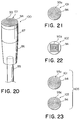
- a round and flat spiral pattern 93a is used as an electrode pattern 93 having the same outside dimension as that of a sleeve 87 working as a feed point.
- the spiral pattern 93a is formed on the surface of a circular printed board 94 and has an initial wind part connected to the underside of the printed board 94 via a through hole (not shown), so as to form an antenna member 101.
- the antenna member 101 is fixed to the sleeve 87 by soldering or under pressure so as to be fed with power.
- An actual product has a cap (not shown) for antenna protection.
- the spiral pattern 93a is formed by etching the printed board 94.
- a pattern width can be achieved with an accuracy of ⁇ 20 ⁇ m error. Therefore, the line capacitance can be constant without using the member for uniforming the pitches as required in the conventional helical coil so that the dispersion in resonance frequency can be suppressed.
- Reduction in weight of a small-size antenna 100 can also be achieved. Further, since the printed board 94 is only connected onto the sleeve 87 upon assembling, the productivity is high. Moreover, since the feed point is determined by fixing the printed board 94, the dispersion in resonance frequency due to dispersion in feed point can also be suppressed.
- a telescopic whip antenna as a multi-band antenna according to the sixteenth preferred embodiment of the present invention will be described.
- the telescopic whip antenna in this embodiment is the same in structure as the telescopic whip antenna shown in Fig. 20 except that, instead of the round spiral pattern 93a shown in Fig. 21, an angular spiral pattern 93b having the same outside dimension as that of a sleeve 87 working as a feed point is used.
- the angular spiral pattern 93b is formed on the surface of a circular printed board 94 and has an initial wind part connected to the underside of the printed board 94 via a through hole (not shown), so as to form an antenna member 102.
- the antenna member 102 is fixed to the sleeve 87 by soldering or under pressure so as to be fed with power.
- An actual product has a cap (not shown) for antenna protection.
- the spiral pattern 93b is formed by etching the printed board 94.
- a pattern width can be achieved with an accuracy of ⁇ 20 ⁇ m error. Therefore, the line capacitance can be constant without using the member for uniforming the pitches as required in the conventional helical coil so that the dispersion in resonance frequency can be suppressed. Reduction in weight of a small-size antenna 100 can also be achieved.
- the printed board 94 is only connected onto the sleeve 87 upon assembling, the productivity is high.
- the feed point is determined by fixing the printed board 94, the dispersion in resonance frequency due to dispersion in feed point can also be suppressed.
- a telescopic whip antenna as a multi-band antenna according to the seventeenth preferred embodiment of the present invention will be described.
- a pair of boards 94, 94 respectively formed with round spiral patterns 93a and 93c each having the same outside dimension as that of a sleeve 87 working as a feed point are stacked with each other so as to ensure a pattern length.
- the spiral patterns 93a and 93c formed on the printed boards 94, 94 have winding directions opposite to each other, that is, a clockwise winding direction and a counterclockwise winding direction.
- the spiral patterns 93a and 93c have their respective initial wind parts connected to the undersides of the corresponding printed boards 94, 94 via corresponding through holes (not shown), so as to form an antenna member 105.
- the antenna member 105 is fixed to the sleeve 87 by soldering or under pressure so as to be fed with power.
- An actual product has a cap (not shown) for antenna protection.
- each of the spiral patterns 93a and 93c is formed by etching the corresponding printed board 94.
- a pattern width can be achieved with an accuracy of ⁇ 20 ⁇ m error. Therefore, the line capacitance C can be constant so that the dispersion in resonance frequency can be suppressed. Reduction in weight of the small-size antenna can also be achieved.
- the antenna member 105 is only connected onto the sleeve 87 upon assembling, the productivity is high.
- the feed point is determined by fixing the antenna member 105, the dispersion in resonance frequency due to dispersion in feed point can also be suppressed.
- a telescopic whip antenna as a multi-band antenna according to the eighteenth preferred embodiment of the present invention will be described.
- a small-size antenna 110 is provided with an antenna member 115 constituted by forming a meander pattern 112 on a flexible board 111 as best shown in Fig. 25 and then winding it around a cylindrical resin member 114 as best shown in Fig. 26.
- connection electrode 113 For power feeding from one end of the meander pattern 112, a connection electrode 113 provided at one end of the flexible board 111 and the meander pattern 112 are connected to each other.
- the connection electrode 113 of the antenna member 115 and a sleeve 87 are connected to each other by soldering or under pressure for power feeding.
- the meander pattern 112 is formed by etching the flexible board 111 having a conductive metal foil thereover.
- a pattern width can be achieved with an accuracy of ⁇ 20 ⁇ m error. Therefore, the line capacitance C can be constant so that the dispersion in resonance frequency can be suppressed.
- the flexible board 111 is only connected onto the sleeve 87 upon assembling, the productivity is high. Moreover, since the feed point is determined by fixing the flexible board 111, the dispersion in resonance frequency due to dispersion in feed point can also be suppressed.
- the small-size antenna and the rod antenna which is receivable in the casing of the radio device and expandable are combined to provide the telescopic whip antenna.
- the electrode pattern is formed on the printed board, the flexible board or the dielectric board.
Landscapes
- Engineering & Computer Science (AREA)
- Computer Networks & Wireless Communication (AREA)
- Details Of Aerials (AREA)
- Support Of Aerials (AREA)
Abstract
Description
According to still another aspect of the present invention, there is provided a multi-band helical antenna comprising a plurality of helical coils, at least one helical guide around which the plurality of helical coils are wound, and a conductive holder holding the at least one helical guide, wherein power is fed from the conductive holder to at least one of the plurality of helical coils so as to obtain a plurality of resonance frequencies.







Claims (16)
- A multi-band antenna (10, 20, 30, 40) comprising an antenna element having an LC parallel resonance circuit (C, L) and a first (1) and a second (2) radiation element connected to opposite ends of said LC parallel resonance circuit,
wherein said LC parallel resonance circuit is constituted by self-resonance of an inductor (3) itself. - An antenna as claimed in claim 1, wherein said inductor (3) is mounted on a printed board, and/or has an inductance L given by L ≥ 7nH.
- An antenna as claimed in claim 1 or 2, wherein said first radiation element (1) has a helical shape, preferably a part of said first radiation element (1) provides the self-resonance which constitutes said LC parallel resonance circuit (C, L).
- An antenna as claimed in one of claims 1 to 3, wherein said LC parallel resonance circuit and said first radiation element are covered with an insulating material (8) through molding, preferably said insulating material is one of polymer and elastomer which are flexible.
- An antenna as claimed in one of claims 1 to 4, wherein said first radiation element is in the form of a printed board (24) having a meander pattern (22),
preferably a part of said meander pattern provides the self-resonance which constitutes said LC parallel resonance circuit, preferably said LC parallel resonance circuit is mounted on said printed board, and/or said printed board is covered through molding with flexible insulating resin material preferably from the group consisting of polymer and elastomer. - An antenna as claimed in one of claims 1 to 5, wherein said second radiation element (2) is elongate and made of a superelastic alloy, preferably said second radiation element is covered through molding with flexible insulating resin material preferably from the group consisting of polymer and elastomer.
- A telescopic multi-band whip antenna comprising a small-size antenna (42) and a whip antenna (41) which is receivable in a radio device casing and expandable, wherein said small-size antenna is located outside said radio device casing, said whip antenna (41) being slidable relative to said small-size antenna (42), each of said small-size antenna (42) and said whip antenna (41) both having multi-band characteristics so that the multi-band characteristics are obtained both upon putting back and expansion of said whip antenna (41).
- An antenna as claimed in claim 7, wherein said radio device casing is provided with a holder (49) for fixing said small-size antenna (42), said whip antenna (41) being provided at upper and lower end portions thereof with a first and a second stopper (46) which are held by said holder (49) upon putting back and expansion of said whip antenna (41), said first and second stoppers being electrically insulated from said holder (49),
preferably said whip antenna (41) is electrically separated from said small-size antenna (42) by said first stopper when said whip antenna (41) slides in said holder (49) to be received in said radio device casing and/or said whip antenna comprises an LC parallel resonance circuit (43) including a chip inductor and a chip capacitor, and a metal radiation element connected to said LC parallel resonance cirucuit (43). - An antenna as claimed in claim 7 or 8, wherein said whip antenna is in the form of a combination of self-resonance of a chip inductor and a metal radiation element connected thereto, a combination of a distributed constant parallel resonance circuit as an LC parallel resonance circuit, and a metal radiation element, or a combination of self-resonance due to an air-core coil as an LC parallel resonance circuit, and a metal radiation element, said metal radiation element is preferably made of a Ti-Ni alloy.
- An antenna as claimed in one of claims 7 to 9, wherein said small-size antenna is in the form of a combination of an LC parallel resonance circuit having a chip inductor and a chip capacitor, and a helical coil connected thereto, a combination of self-resonance of a chip inductor and a helical coil connected thereto, a combination of self-resonance of an air-core coil and a helical coil connected thereto, a combination of an LC parallel resonance circuit (53) comprising a chip inductor and a chip capacitor mounted on a flexible board, and a meander pattern (59) formed on said flexible board, a combination of a self-resonance circuit having a chip inductor and working as an LC parallel resonance circuit, and a meander pattern, said self-resonance circuit and said meander pattern provided on a flexible board, a combination of a self-resonance circuit having an air-core coil and working as an LC parallel resonance circuit, and a meander pattern, said self-resonance circuit and said meander pattern being provided on a flexible board, or a combination of a distributed constant parallel resonance circuit and a meander pattern (69) both provided on a flexible board.
- A multi-band helical antenna (72) comprising a plurality of helical coils (74), at least one helical guide around which said plurality of helical coils (74) are wound, and a conductive holder (76) holding said at least one helical guide (75), wherein power is fed from said conductive holder (76) to at least one of said plurality of helical coils (74) so as to obtain a plurality of resonance frequencies.
- An antenna as claimed in claim 11, wherein said plurality of helical coils (74) have the same diameter and the different numbers of turns and are wound around said helical guide (75) parallelly, or have different diameters and the different numbers of turns and are parallelly wound around said plurality of helical guides (75A, 75B) having different diameters and arranged concentrically and overlapped with each other, the power being fed from said holder (76) to said plurality of helical coils (74), respectively; or have the same diameter and the different numbers of turns and are wound around said helical guide (75) in series, or have different diameters and the different numbers of turns and are wound in series around said plurality of helical guides (75A, 75B) having different diameters and arranged concentrically and overlapped with each other, the power being fed from said holder (76) to one of said plurality of helical coils (74).
- A multi-band helical antenna comprising:a plurality of helical coils (74) having the same diameter and the different numbers of turns;a helical guide (75) around which said plurality of helical coils are wound;an insulating portion (78) beind a dielectric and provided on a surface of said helical guide (75) to separate said plurality of helical coils (74) from each other; anda conductive holder (76) holding said helical guide (75), power being fed from said holder (76) to one of said plurality of helical coils (74) and further fed to the other helical coil (74) through capacitive coupling so as to obtain a plurality of resonance frequencies.
- A telescopic whip antenna comprising a rod antenna (85) which is receivable in a casing and expandable, and a small-size antenna (90) provided at an upper portion of said rod antenna (85), wherein power is fed to said rod antenna (85) upon expansion and to said small-size antenna (90) upon putting back, said small-size antenna (90) being substantially in the form of a board (82) made of an insulating material and formed thereon with an electrode pattern (83) and uses a resonance frequency based on a dielectric constant of said board (82) and said electrode pattern.
- An antenna as claimed in claim 14, wherein said electrode pattern (83) comprises at least one of a meander line pattern (83a), a sawtooth line pattern (83b) and a spiral pattern (83c) and/or said small-size antenna (90) comprises stacked boards (94) each formed thereon with a spiral pattern (93a, 93b, 93c).
- An antenna as claimed in claim 14 or 15, wherein said board is substantially in the form of at least one of a printed board (94), a flexible board (111) and a dielectric board,
preferably said board comprises the flexible board, said electrode pattern comprising a meander or sawtooth line pattern (112) formed on said flexible board (111), said small-size antenna being in the form of said flexible board (111) formed thereon with said meander or sawtooth line pattern, said flexible board (111) being wound into a cylindrical shape and fixed, and/or said board (94) formed thereon with said electrode pattern (93) is fixed by soldering or under pressure to a sleeve (87) for feeding power to said small-size antenna (100, 110) upon putting back.
Priority Applications (1)
| Application Number | Priority Date | Filing Date | Title |
|---|---|---|---|
| EP01105105A EP1119074A3 (en) | 1997-08-07 | 1998-08-03 | Multi-band antenna suitable for use in a mobile radio device |
Applications Claiming Priority (12)
| Application Number | Priority Date | Filing Date | Title |
|---|---|---|---|
| JP21286797A JP3243637B2 (en) | 1997-08-07 | 1997-08-07 | Multi-band antenna for portable radio |
| JP21286797 | 1997-08-07 | ||
| JP212867/97 | 1997-08-07 | ||
| JP345304/97 | 1997-12-15 | ||
| JP34530497A JP3225438B2 (en) | 1997-12-15 | 1997-12-15 | Telescopic multi-band whip antenna |
| JP34530497 | 1997-12-15 | ||
| JP8121198 | 1998-03-27 | ||
| JP81211/98 | 1998-03-27 | ||
| JP10081211A JPH11284427A (en) | 1998-03-27 | 1998-03-27 | Multi-band helical antenna |
| JP110783/98 | 1998-04-21 | ||
| JP11078398A JPH11308028A (en) | 1998-04-21 | 1998-04-21 | Telescopic whip antenna |
| JP11078398 | 1998-04-21 |
Related Child Applications (1)
| Application Number | Title | Priority Date | Filing Date |
|---|---|---|---|
| EP01105105A Division EP1119074A3 (en) | 1997-08-07 | 1998-08-03 | Multi-band antenna suitable for use in a mobile radio device |
Publications (3)
| Publication Number | Publication Date |
|---|---|
| EP0896384A2 true EP0896384A2 (en) | 1999-02-10 |
| EP0896384A3 EP0896384A3 (en) | 1999-05-26 |
| EP0896384B1 EP0896384B1 (en) | 2003-10-08 |
Family
ID=27466537
Family Applications (2)
| Application Number | Title | Priority Date | Filing Date |
|---|---|---|---|
| EP98114574A Expired - Lifetime EP0896384B1 (en) | 1997-08-07 | 1998-08-03 | Multi-band antenna suitable for use in a mobile radio device |
| EP01105105A Withdrawn EP1119074A3 (en) | 1997-08-07 | 1998-08-03 | Multi-band antenna suitable for use in a mobile radio device |
Family Applications After (1)
| Application Number | Title | Priority Date | Filing Date |
|---|---|---|---|
| EP01105105A Withdrawn EP1119074A3 (en) | 1997-08-07 | 1998-08-03 | Multi-band antenna suitable for use in a mobile radio device |
Country Status (10)
| Country | Link |
|---|---|
| US (1) | US6163300A (en) |
| EP (2) | EP0896384B1 (en) |
| KR (1) | KR19990023431A (en) |
| CN (1) | CN1218308A (en) |
| AU (1) | AU763364B2 (en) |
| CA (1) | CA2244723A1 (en) |
| DE (1) | DE69818768T2 (en) |
| NO (1) | NO983547L (en) |
| SG (1) | SG92615A1 (en) |
| TW (1) | TW382832B (en) |
Cited By (9)
| Publication number | Priority date | Publication date | Assignee | Title |
|---|---|---|---|---|
| WO2000079644A1 (en) * | 1999-06-17 | 2000-12-28 | Moteco Ab | Antenna device |
| FR2816114A1 (en) * | 2000-10-31 | 2002-05-03 | Schlumberger Systems & Service | MULTIBAND ANTENNA |
| FR2818016A1 (en) * | 2000-12-13 | 2002-06-14 | Sagem | Single block antenna for use with a cellular mobile telephone uses linear polarization and broadband having two sections with a lengthening piece from one straight section to the other spiral one. |
| EP1202383A3 (en) * | 2000-10-31 | 2002-10-23 | Mitsubishi Materials Corporation | Antenna, receiving/transmitting apparatus therewith and method of manufacturing the antenna |
| RU2205477C1 (en) * | 2002-07-10 | 2003-05-27 | Лопатин Игорь Евгеньевич | Antenna |
| EP1329986A1 (en) * | 2002-01-17 | 2003-07-23 | Calearo S.r.l. | Compact antenna for vehicles |
| US6674405B2 (en) | 2001-02-15 | 2004-01-06 | Benq Corporation | Dual-band meandering-line antenna |
| WO2004049499A3 (en) * | 2002-11-27 | 2005-02-24 | Matsushita Electric Industrial Co Ltd | Chip antenna |
| EP2642591A3 (en) * | 2012-03-21 | 2014-05-14 | Samsung Electronics Co., Ltd | Antenna device for wireless communication terminal |
Families Citing this family (38)
| Publication number | Priority date | Publication date | Assignee | Title |
|---|---|---|---|---|
| US6297784B1 (en) * | 1998-11-02 | 2001-10-02 | Auden Techno Corp. | Bi-frequency cellular telephone antenna |
| JP3788115B2 (en) * | 1999-07-23 | 2006-06-21 | 松下電器産業株式会社 | Method for manufacturing antenna device |
| JP4242528B2 (en) * | 1999-10-26 | 2009-03-25 | パナソニック株式会社 | Antenna fixing method and apparatus |
| US7158819B1 (en) * | 2000-06-29 | 2007-01-02 | Motorola, Inc. | Antenna apparatus with inner antenna and grounded outer helix antenna |
| US6369775B1 (en) * | 2000-09-25 | 2002-04-09 | Amphenol-T&M Antennas | Antenna assembly and multiband stubby antenna |
| KR100381549B1 (en) * | 2001-01-22 | 2003-04-23 | 주식회사 선우커뮤니케이션 | Wideband micristrip omni-antenna |
| US20020119801A1 (en) * | 2001-02-28 | 2002-08-29 | Yasushi Nemoto | Portable telephone apparatus |
| EP1258945A3 (en) * | 2001-05-16 | 2003-11-05 | The Furukawa Electric Co., Ltd. | Line-shaped antenna |
| JP5028720B2 (en) * | 2001-07-11 | 2012-09-19 | Necネットワークプロダクツ株式会社 | Antenna device |
| JP3759143B2 (en) * | 2001-10-13 | 2006-03-22 | サムスン エレクトロニクス カンパニー リミテッド | Mobile communication device having multiband antenna |
| SE0104308D0 (en) * | 2001-12-19 | 2001-12-19 | Nikolai Roshchupkin | Antenna for mobile phone and other radio equipment |
| US6720935B2 (en) | 2002-07-12 | 2004-04-13 | The Mitre Corporation | Single and dual-band patch/helix antenna arrays |
| ATE416493T1 (en) * | 2003-04-04 | 2008-12-15 | Zweidorff Hannah B | DEVICE FOR SHIELDING ELECTRONIC SECURITY UNITS WITH TRANSMITTING/RECEIVING DEVICES AND IN PARTICULAR FOR SHIELDING MOBILE PHONES |
| CN1823396B (en) * | 2003-07-11 | 2010-05-12 | Nxp股份有限公司 | Inductive system and manufacturing method thereof, printed circuit board and tuner |
| FR2863407B1 (en) * | 2003-12-04 | 2006-03-24 | Sagem | BI-BAND MOBILE TELEPHONE WITH OMNIDIRECTIONAL RADIATION DIAGRAM |
| US7161538B2 (en) * | 2004-05-24 | 2007-01-09 | Amphenol-T&M Antennas | Multiple band antenna and antenna assembly |
| EP1757216A4 (en) * | 2004-05-27 | 2009-08-05 | Panasonic Corp | TRANSMITTER, RECEIVER AND TRANSMIT / RECEIVE SYSTEM |
| US20090269078A1 (en) * | 2005-02-16 | 2009-10-29 | Kazunori Miyoshi | Dispersion compensator and optical communication device having same |
| KR100788676B1 (en) * | 2005-12-21 | 2007-12-26 | 삼성전자주식회사 | Antenna unit, antenna unit control method and mobile terminal having the antenna unit |
| KR100731600B1 (en) * | 2005-12-26 | 2007-06-22 | (주)에이스안테나 | Integrated chip antenna with complementary radiator structure |
| US7397441B1 (en) * | 2007-02-02 | 2008-07-08 | Sony Ericsson Mobile Communications Ab | Antenna element for a portable communication device |
| US7612723B2 (en) * | 2007-02-02 | 2009-11-03 | Sony Ericsson Mobile Communications Ab | Portable communication device antenna arrangement |
| KR101251889B1 (en) * | 2009-06-19 | 2013-04-08 | (주)파트론 | Broadcast receiving antenna having inductor chip mounted |
| US8395233B2 (en) * | 2009-06-24 | 2013-03-12 | Harris Corporation | Inductor structures for integrated circuit devices |
| CN102150327B (en) * | 2009-07-10 | 2014-06-11 | 松下电器产业株式会社 | Antenna apparatus and wireless communication apparatus |
| FI20096320A0 (en) * | 2009-12-14 | 2009-12-14 | Pulse Finland Oy | Multiband antenna structure |
| US8179221B2 (en) * | 2010-05-20 | 2012-05-15 | Harris Corporation | High Q vertical ribbon inductor on semiconducting substrate |
| KR101118051B1 (en) * | 2010-06-23 | 2012-02-24 | 인천대학교 산학협력단 | Multiband rod antenna using trap |
| US8462064B2 (en) | 2010-07-29 | 2013-06-11 | Harris Corporation | Multiband dismount antenna |
| US8304855B2 (en) | 2010-08-04 | 2012-11-06 | Harris Corporation | Vertical capacitors formed on semiconducting substrates |
| JP5291136B2 (en) * | 2011-03-22 | 2013-09-18 | 株式会社日本自動車部品総合研究所 | Multiband antenna |
| JP5260811B1 (en) | 2011-07-11 | 2013-08-14 | パナソニック株式会社 | ANTENNA DEVICE AND WIRELESS COMMUNICATION DEVICE |
| KR101255156B1 (en) * | 2011-12-20 | 2013-04-22 | 주식회사 이엠따블유 | Apparatus for wireless communication |
| KR101369940B1 (en) * | 2012-01-18 | 2014-03-04 | 양묘근 | Dual band rod antenna and mobile device comprsing the same |
| WO2018129019A2 (en) * | 2017-01-04 | 2018-07-12 | Laird Technologies, Inc. | Molding designs for helical antennas |
| TWI643399B (en) * | 2017-08-01 | 2018-12-01 | 譁裕實業股份有限公司 | Dipole antenna vibrator |
| WO2021065296A1 (en) | 2019-10-03 | 2021-04-08 | 株式会社村田製作所 | Antenna device and wireless communication device including same |
| CN119629899A (en) * | 2023-09-07 | 2025-03-14 | 荣耀终端股份有限公司 | Electronic devices |
Family Cites Families (32)
| Publication number | Priority date | Publication date | Assignee | Title |
|---|---|---|---|---|
| US1783025A (en) * | 1924-07-25 | 1930-11-25 | Drahtlose Telegraphie Mbh | Antenna |
| BE476416A (en) * | 1946-10-01 | 1900-01-01 | ||
| US5734352A (en) * | 1992-08-07 | 1998-03-31 | R. A. Miller Industries, Inc. | Multiband antenna system |
| AU2284370A (en) * | 1970-11-30 | 1972-06-01 | Normal-mode helix aerials | |
| US4080604A (en) * | 1976-09-21 | 1978-03-21 | Robyn International, Inc. | Means for tuning a loaded coil antenna |
| US4490727A (en) * | 1979-10-18 | 1984-12-25 | Mobile Mark, Inc. | Adjustable top loaded antenna |
| US4924238A (en) * | 1987-02-06 | 1990-05-08 | George Ploussios | Electronically tunable antenna |
| US4772895A (en) * | 1987-06-15 | 1988-09-20 | Motorola, Inc. | Wide-band helical antenna |
| US5022051A (en) * | 1988-11-02 | 1991-06-04 | Hewlett-Packard Company | DC-free line code for arbitrary data transmission |
| JP2568281B2 (en) * | 1989-11-17 | 1996-12-25 | 原田工業株式会社 | Three-wave shared antenna for automobiles |
| JP2832476B2 (en) * | 1990-02-14 | 1998-12-09 | 望 長谷部 | Helical antenna |
| EP0470797A3 (en) * | 1990-08-10 | 1992-05-13 | Matsushita Electric Industrial Co., Ltd | Antenna apparatus |
| JPH04334201A (en) * | 1991-05-10 | 1992-11-20 | Nishikiori:Kk | Antenna |
| WO1994003939A1 (en) * | 1992-08-07 | 1994-02-17 | R.A. Miller Industries, Inc. | Multiband antenna system |
| JP2809365B2 (en) * | 1992-09-28 | 1998-10-08 | エヌ・ティ・ティ移動通信網株式会社 | Portable radio |
| GB2271670B (en) * | 1992-10-14 | 1996-10-16 | Nokia Mobile Phones Uk | Wideband antenna arrangement |
| JPH06216630A (en) * | 1993-01-14 | 1994-08-05 | Nippon Antenna Kk | Expansion whip antenna |
| JP2520557B2 (en) * | 1993-02-26 | 1996-07-31 | 日本電気株式会社 | Radio antenna |
| JP2730480B2 (en) * | 1993-07-30 | 1998-03-25 | 日本アンテナ株式会社 | 3 wave shared roof antenna |
| KR960010858B1 (en) * | 1993-05-21 | 1996-08-10 | 삼성전자 주식회사 | Portable radio antenna |
| SE9301761L (en) * | 1993-05-24 | 1994-06-06 | Allgon Ab | Antenna device for portable communication equipment |
| EP0634806A1 (en) * | 1993-07-13 | 1995-01-18 | Kabushiki Kaisha Yokowo | Radio antenna |
| JPH0786819A (en) * | 1993-09-09 | 1995-03-31 | Mitsubishi Electric Corp | Antenna device |
| JPH08186420A (en) * | 1994-12-28 | 1996-07-16 | Zanavy Informatics:Kk | Print antenna |
| JPH08191459A (en) * | 1995-01-10 | 1996-07-23 | Sony Corp | Video signal processing circuit |
| KR0162679B1 (en) * | 1995-03-22 | 1998-12-01 | 구관영 | Retractable antenna using capacitive coupled |
| FI109493B (en) * | 1995-04-07 | 2002-08-15 | Filtronic Lk Oy | An elastic antenna structure and a method for its manufacture |
| JP2795825B2 (en) * | 1995-06-30 | 1998-09-10 | エスエムケイ株式会社 | Antenna device |
| JPH0946259A (en) * | 1995-08-02 | 1997-02-14 | Matsushita Electric Ind Co Ltd | Antenna device |
| JP3243595B2 (en) * | 1995-10-31 | 2002-01-07 | 株式会社トーキン | Multi-band antenna and multi-band portable radio using the same |
| WO1997018601A1 (en) * | 1995-11-15 | 1997-05-22 | Allgon Ab | Dual band antenna means |
| KR19990010968A (en) * | 1997-07-19 | 1999-02-18 | 윤종용 | Dual band antenna |
-
1998
- 1998-07-23 US US09/121,422 patent/US6163300A/en not_active Expired - Fee Related
- 1998-07-29 TW TW087112429A patent/TW382832B/en not_active IP Right Cessation
- 1998-07-31 SG SG9802820A patent/SG92615A1/en unknown
- 1998-07-31 NO NO983547A patent/NO983547L/en not_active Application Discontinuation
- 1998-08-03 EP EP98114574A patent/EP0896384B1/en not_active Expired - Lifetime
- 1998-08-03 AU AU78637/98A patent/AU763364B2/en not_active Ceased
- 1998-08-03 EP EP01105105A patent/EP1119074A3/en not_active Withdrawn
- 1998-08-03 DE DE69818768T patent/DE69818768T2/en not_active Expired - Fee Related
- 1998-08-05 CA CA002244723A patent/CA2244723A1/en not_active Abandoned
- 1998-08-06 CN CN98118019A patent/CN1218308A/en active Pending
- 1998-08-07 KR KR1019980032108A patent/KR19990023431A/en not_active Ceased
Cited By (14)
| Publication number | Priority date | Publication date | Assignee | Title |
|---|---|---|---|---|
| WO2000079644A1 (en) * | 1999-06-17 | 2000-12-28 | Moteco Ab | Antenna device |
| US6680713B2 (en) | 2000-10-31 | 2004-01-20 | Mitsubishi Materials Corporation | Antenna and radio wave receiving/transmitting apparatus therewith and method of manufacturing the antenna |
| FR2816114A1 (en) * | 2000-10-31 | 2002-05-03 | Schlumberger Systems & Service | MULTIBAND ANTENNA |
| WO2002037606A1 (en) * | 2000-10-31 | 2002-05-10 | Schlumberger Systemes | Multiband antenna |
| EP1202383A3 (en) * | 2000-10-31 | 2002-10-23 | Mitsubishi Materials Corporation | Antenna, receiving/transmitting apparatus therewith and method of manufacturing the antenna |
| FR2818016A1 (en) * | 2000-12-13 | 2002-06-14 | Sagem | Single block antenna for use with a cellular mobile telephone uses linear polarization and broadband having two sections with a lengthening piece from one straight section to the other spiral one. |
| GB2376133A (en) * | 2000-12-13 | 2002-12-04 | Sagem | Single block broadband antenna for use with cellular mobile telephones |
| GB2376133B (en) * | 2000-12-13 | 2004-12-08 | Sagem | Linearly polarised monobloc antenna and mobile terminal of cellular radiotelephony comprising such an antenna |
| US6674405B2 (en) | 2001-02-15 | 2004-01-06 | Benq Corporation | Dual-band meandering-line antenna |
| EP1329986A1 (en) * | 2002-01-17 | 2003-07-23 | Calearo S.r.l. | Compact antenna for vehicles |
| RU2205477C1 (en) * | 2002-07-10 | 2003-05-27 | Лопатин Игорь Евгеньевич | Antenna |
| WO2004049499A3 (en) * | 2002-11-27 | 2005-02-24 | Matsushita Electric Industrial Co Ltd | Chip antenna |
| US7042418B2 (en) | 2002-11-27 | 2006-05-09 | Matsushita Electric Industrial Co., Ltd. | Chip antenna |
| EP2642591A3 (en) * | 2012-03-21 | 2014-05-14 | Samsung Electronics Co., Ltd | Antenna device for wireless communication terminal |
Also Published As
| Publication number | Publication date |
|---|---|
| SG92615A1 (en) | 2002-11-19 |
| EP1119074A2 (en) | 2001-07-25 |
| AU7863798A (en) | 1999-02-18 |
| AU763364B2 (en) | 2003-07-17 |
| CN1218308A (en) | 1999-06-02 |
| DE69818768D1 (en) | 2003-11-13 |
| EP0896384B1 (en) | 2003-10-08 |
| TW382832B (en) | 2000-02-21 |
| US6163300A (en) | 2000-12-19 |
| NO983547L (en) | 1999-02-08 |
| DE69818768T2 (en) | 2004-08-12 |
| EP1119074A3 (en) | 2001-09-05 |
| NO983547D0 (en) | 1998-07-31 |
| EP0896384A3 (en) | 1999-05-26 |
| KR19990023431A (en) | 1999-03-25 |
| CA2244723A1 (en) | 1999-02-07 |
Similar Documents
| Publication | Publication Date | Title |
|---|---|---|
| EP0896384B1 (en) | Multi-band antenna suitable for use in a mobile radio device | |
| US5541610A (en) | Antenna for a radio communication apparatus | |
| US5990848A (en) | Combined structure of a helical antenna and a dielectric plate | |
| FI115086B (en) | Chip antenna and radio apparatus with chip antenna | |
| KR100414765B1 (en) | Ceramic chip antenna | |
| EP0743699B1 (en) | Surface mounting type antenna system | |
| CN1307743C (en) | multi-frequency antenna | |
| EP3133695B1 (en) | Antenna system and antenna module with reduced interference between radiating patterns | |
| EP0863570A2 (en) | A chip antenna and a method for adjusting frequency of the same | |
| KR20040028739A (en) | Broad-band antenna for mobile communication | |
| US6232925B1 (en) | Antenna device | |
| US20100207832A1 (en) | Antenna arrangement, printed circuit board, portable electronic device & conversion kit | |
| NZ264417A (en) | Printed film helical radio antenna with pitch varying from base to apex of helix | |
| WO1999052175A1 (en) | Wide band antenna means incorporating a radiating structure having a band form | |
| EP0717881A1 (en) | Aerial coupling means | |
| EP0863571A2 (en) | A mobile image apparatus and an antenna apparatus used for the mobile image apparatus | |
| US6778149B2 (en) | Composite antenna apparatus | |
| KR20000010756A (en) | Antenna device having a matching means | |
| US6348900B1 (en) | Antenna assembly | |
| EP0772255A1 (en) | Multiband antenna with a distributed-constant dielectric resonant circuit, and multiband portable radio apparatus comprising such an antenna | |
| CN100511837C (en) | Antenna device and wireless communication device using same | |
| EP0987788A2 (en) | Multiple band antenna | |
| JP3243637B2 (en) | Multi-band antenna for portable radio | |
| JPH1098405A (en) | Antenna system | |
| KR200284259Y1 (en) | A portable phone antenna having the zig-zag shaped line |
Legal Events
| Date | Code | Title | Description |
|---|---|---|---|
| PUAI | Public reference made under article 153(3) epc to a published international application that has entered the european phase |
Free format text: ORIGINAL CODE: 0009012 |
|
| AK | Designated contracting states |
Kind code of ref document: A2 Designated state(s): DE FI FR GB IT SE |
|
| AX | Request for extension of the european patent |
Free format text: AL;LT;LV;MK;RO;SI |
|
| PUAL | Search report despatched |
Free format text: ORIGINAL CODE: 0009013 |
|
| AK | Designated contracting states |
Kind code of ref document: A3 Designated state(s): AT BE CH CY DE DK ES FI FR GB GR IE IT LI LU MC NL PT SE |
|
| AX | Request for extension of the european patent |
Free format text: AL;LT;LV;MK;RO;SI |
|
| 17P | Request for examination filed |
Effective date: 19991104 |
|
| AKX | Designation fees paid |
Free format text: DE FI FR GB IT SE |
|
| 17Q | First examination report despatched |
Effective date: 20001025 |
|
| RAP1 | Party data changed (applicant data changed or rights of an application transferred) |
Owner name: NEC TOKIN CORPORATION |
|
| GRAH | Despatch of communication of intention to grant a patent |
Free format text: ORIGINAL CODE: EPIDOS IGRA |
|
| GRAS | Grant fee paid |
Free format text: ORIGINAL CODE: EPIDOSNIGR3 |
|
| GRAA | (expected) grant |
Free format text: ORIGINAL CODE: 0009210 |
|
| AK | Designated contracting states |
Kind code of ref document: B1 Designated state(s): DE FI FR GB IT SE |
|
| REG | Reference to a national code |
Ref country code: GB Ref legal event code: FG4D |
|
| REG | Reference to a national code |
Ref country code: SE Ref legal event code: TRGR |
|
| REF | Corresponds to: |
Ref document number: 69818768 Country of ref document: DE Date of ref document: 20031113 Kind code of ref document: P |
|
| ET | Fr: translation filed | ||
| PG25 | Lapsed in a contracting state [announced via postgrant information from national office to epo] |
Ref country code: GB Free format text: LAPSE BECAUSE OF NON-PAYMENT OF DUE FEES Effective date: 20040803 Ref country code: FI Free format text: LAPSE BECAUSE OF NON-PAYMENT OF DUE FEES Effective date: 20040803 |
|
| PG25 | Lapsed in a contracting state [announced via postgrant information from national office to epo] |
Ref country code: SE Free format text: LAPSE BECAUSE OF NON-PAYMENT OF DUE FEES Effective date: 20040804 |
|
| PLBE | No opposition filed within time limit |
Free format text: ORIGINAL CODE: 0009261 |
|
| STAA | Information on the status of an ep patent application or granted ep patent |
Free format text: STATUS: NO OPPOSITION FILED WITHIN TIME LIMIT |
|
| 26N | No opposition filed |
Effective date: 20040709 |
|
| PG25 | Lapsed in a contracting state [announced via postgrant information from national office to epo] |
Ref country code: DE Free format text: LAPSE BECAUSE OF NON-PAYMENT OF DUE FEES Effective date: 20050301 |
|
| GBPC | Gb: european patent ceased through non-payment of renewal fee |
Effective date: 20040803 |
|
| EUG | Se: european patent has lapsed | ||
| PG25 | Lapsed in a contracting state [announced via postgrant information from national office to epo] |
Ref country code: FR Free format text: LAPSE BECAUSE OF NON-PAYMENT OF DUE FEES Effective date: 20050429 |
|
| REG | Reference to a national code |
Ref country code: FR Ref legal event code: ST |
|
| PG25 | Lapsed in a contracting state [announced via postgrant information from national office to epo] |
Ref country code: IT Free format text: LAPSE BECAUSE OF NON-PAYMENT OF DUE FEES Effective date: 20050803 |
|
| REG | Reference to a national code |
Ref country code: HK Ref legal event code: WD Ref document number: 1017505 Country of ref document: HK |