EP0896083B1 - Improved elastic suspension means for the washing assembly of a washing machine - Google Patents
Improved elastic suspension means for the washing assembly of a washing machine Download PDFInfo
- Publication number
- EP0896083B1 EP0896083B1 EP98111482A EP98111482A EP0896083B1 EP 0896083 B1 EP0896083 B1 EP 0896083B1 EP 98111482 A EP98111482 A EP 98111482A EP 98111482 A EP98111482 A EP 98111482A EP 0896083 B1 EP0896083 B1 EP 0896083B1
- Authority
- EP
- European Patent Office
- Prior art keywords
- washing
- rigid member
- washing machine
- suspension means
- end portion
- Prior art date
- Legal status (The legal status is an assumption and is not a legal conclusion. Google has not performed a legal analysis and makes no representation as to the accuracy of the status listed.)
- Expired - Lifetime
Links
- 238000005406 washing Methods 0.000 title claims description 66
- 239000000725 suspension Substances 0.000 title claims description 35
- 230000006835 compression Effects 0.000 claims description 10
- 238000007906 compression Methods 0.000 claims description 10
- 230000000717 retained effect Effects 0.000 claims description 5
- 239000004033 plastic Substances 0.000 claims description 2
- 229920003023 plastic Polymers 0.000 claims description 2
- 239000000243 solution Substances 0.000 description 5
- 229910000831 Steel Inorganic materials 0.000 description 4
- 238000004873 anchoring Methods 0.000 description 4
- 239000010959 steel Substances 0.000 description 4
- 239000006096 absorbing agent Substances 0.000 description 3
- 238000010276 construction Methods 0.000 description 3
- 230000035939 shock Effects 0.000 description 3
- 238000000605 extraction Methods 0.000 description 2
- 239000000463 material Substances 0.000 description 2
- 239000002184 metal Substances 0.000 description 2
- 125000006850 spacer group Chemical group 0.000 description 2
- XLYOFNOQVPJJNP-UHFFFAOYSA-N water Substances O XLYOFNOQVPJJNP-UHFFFAOYSA-N 0.000 description 2
- 238000001035 drying Methods 0.000 description 1
- 230000000694 effects Effects 0.000 description 1
- 230000002349 favourable effect Effects 0.000 description 1
- 238000001746 injection moulding Methods 0.000 description 1
- 238000004519 manufacturing process Methods 0.000 description 1
- 239000002991 molded plastic Substances 0.000 description 1
- 230000002035 prolonged effect Effects 0.000 description 1
- 230000000284 resting effect Effects 0.000 description 1
Images

Classifications
-
- F—MECHANICAL ENGINEERING; LIGHTING; HEATING; WEAPONS; BLASTING
- F16—ENGINEERING ELEMENTS AND UNITS; GENERAL MEASURES FOR PRODUCING AND MAINTAINING EFFECTIVE FUNCTIONING OF MACHINES OR INSTALLATIONS; THERMAL INSULATION IN GENERAL
- F16F—SPRINGS; SHOCK-ABSORBERS; MEANS FOR DAMPING VIBRATION
- F16F3/00—Spring units consisting of several springs, e.g. for obtaining a desired spring characteristic
- F16F3/02—Spring units consisting of several springs, e.g. for obtaining a desired spring characteristic with springs made of steel or of other material having low internal friction
- F16F3/04—Spring units consisting of several springs, e.g. for obtaining a desired spring characteristic with springs made of steel or of other material having low internal friction composed only of wound springs
-
- D—TEXTILES; PAPER
- D06—TREATMENT OF TEXTILES OR THE LIKE; LAUNDERING; FLEXIBLE MATERIALS NOT OTHERWISE PROVIDED FOR
- D06F—LAUNDERING, DRYING, IRONING, PRESSING OR FOLDING TEXTILE ARTICLES
- D06F37/00—Details specific to washing machines covered by groups D06F21/00 - D06F25/00
- D06F37/20—Mountings, e.g. resilient mountings, for the rotary receptacle, motor, tub or casing; Preventing or damping vibrations
-
- F—MECHANICAL ENGINEERING; LIGHTING; HEATING; WEAPONS; BLASTING
- F16—ENGINEERING ELEMENTS AND UNITS; GENERAL MEASURES FOR PRODUCING AND MAINTAINING EFFECTIVE FUNCTIONING OF MACHINES OR INSTALLATIONS; THERMAL INSULATION IN GENERAL
- F16F—SPRINGS; SHOCK-ABSORBERS; MEANS FOR DAMPING VIBRATION
- F16F1/00—Springs
- F16F1/02—Springs made of steel or other material having low internal friction; Wound, torsion, leaf, cup, ring or the like springs, the material of the spring not being relevant
- F16F1/04—Wound springs
- F16F1/12—Attachments or mountings
- F16F1/128—Attachments or mountings with motion-limiting means, e.g. with a full-length guide element or ball joint connections; with protective outer cover
-
- F—MECHANICAL ENGINEERING; LIGHTING; HEATING; WEAPONS; BLASTING
- F16—ENGINEERING ELEMENTS AND UNITS; GENERAL MEASURES FOR PRODUCING AND MAINTAINING EFFECTIVE FUNCTIONING OF MACHINES OR INSTALLATIONS; THERMAL INSULATION IN GENERAL
- F16F—SPRINGS; SHOCK-ABSORBERS; MEANS FOR DAMPING VIBRATION
- F16F9/00—Springs, vibration-dampers, shock-absorbers, or similarly-constructed movement-dampers using a fluid or the equivalent as damping medium
- F16F9/32—Details
- F16F9/54—Arrangements for attachment
Definitions
- the present invention generally refers to washing machines, including the so-called washer-dryers, in particular residential-type clothes washing and combined clothes washing and drying machines, and namely the supension means for the washing assembly thereof.
- Washing machines of the above cited kind are generally known to comprise a washing assembly, which substantially consists of a stationary tub, a rotating drum inside said tub, and a drive motor for rotatably driving said drum.
- Elastic means which are usually integrated by friction-type shock absorbers, are used to let said washing assembly be supported by the stationary structure of the washing machine.
- FR-A-2 531 461 which provides for the use of elastic means having a rigidity of an absolute value that increases with the intensity of the stress imposed by the washing assembly during the operation of the washing machine.
- the first rigid member consists of a casing with a first and a second part removably connected to the first part and is provided with an opening through which the second rigid member is capable of sliding.
- EP-A-0 080 243 and EP-A-0 265 004 disclose two respective variants of elastic means for the suspension of the washing assembly, which advantageously double to also perform as friction-type shock absorbers. Both these variants are based on the use of a helical pulling-type or tractive spring arranged inside a rigid tube having an end portion adapted to be attached, for instance, to the outer casing of a washing machine, and capable of sliding under friction within a rigid cylindrical, longitudinally grooved casing that encloses it elastically. The free end portion of said cylindrical casing is in turn adapted to be attached, for instance, to the washing assembly of the machine.
- washing-assembly suspension means that are effective also at the highest rotation speed of the drum (which is in excess of 1500 rpm in some of the most recent models), while keeping the related costs as low as possible.
- Further purposes of the present invention are to provide suspension means that are more reliable of the prior-art ones and are capable of being manufactured in an economical and rational manner in all variants as may be required by a range of washing machine models that typically includes a large variety of sizes, load capacities, constructions of the washing assembly and rotating speeds of the drum.
- a suspension means for suspending the washing assembly to the outer casing of a washing machine, substantially consists of a first and a second rigid member, which are generally indicated at 10 and 20, respectively, as well as two helical springs 30 and 40 having a different elastic constant and arranged in series with respect to each other, wherein all these parts of the suspension means are aligned along the same axis X - X.
- the first rigid member 10 is a casing, which essentially consists of a first and a second cylindrically shaped part 11 and 12 of plastic material, produced by injection moulding, which are snap-fitted together thanks to respective circumferential male and female protrusions 13 and 14, respectively, which allow for the same parts to be separated from each other through the use of an appropriate tool.
- the first end portion 15 (ie. the upper one) of said first part 11 of the first rigid member 10 forms a seat in which the metal hinging pin 16 is retained for a first protruding steel hook 17 used for anchoring the suspension means on to the outer casing of the washing machine (as shown schematically with an eyelet M in Figures 2 and 3, for reasons of greater simplicity).
- the first end portion 15a of said first part 11 of the first rigid member 10 comprises a downward oriented appendix 16a on which a first steel hook 17a is provided by overmoulding, whose protruding portion is used for anchoring the suspension means on to the outer casing of the washing machine (as shown schematically with an eyelet P in Figure 4 for reasons of greater simplicity).
- the second end portion (ie. the lower one) of the same first part 11 of the first rigid member 10 is, in both above cited embodiments, open so as to enable the second rigid element 20 to pass therethrough.
- the first end portion (ie. the upper one) of said second part 12 of the first rigid member 10 is provided with the afore mentioned male-type protrusions 13 for joining with said first part 11.
- the second end portion (ie. the lower one) of the same second part 12 of the first rigid member 10 has a central opening 18 that is delimited by an annular edge 19 against which an end portion of the second spring 40 is caused to abut, as this will be described in greater detail further on.
- the second rigid member 20 which is also made of injection-moulded plastic material, has a body in the shape of a goblet, or elongated bowl, and is arranged slidably inside the first rigid member 10 through the opening 18.
- the first end portion (ie. the upper one) of said second rigid member 20 has a central opening 21 defined by a downward facing annular edge 22, against which an end portion of the first spring 30 is caused to abut, as this will be described in greater detail further on.
- the second end portion 33 of said second rigid member 20 forms a seat in which the metal hinging pin 26 is retained for a second protruding steel hook 27 for anchoring the suspension means on to the washing assembly of the washing machine (as shown schematically with an eyelet N in Figures 2 and 3 for reasons of greater simplicity).
- the suspension plane of the hook 27 may be perpendicular to the suspension plane of the hook 17 (as this is shown in the cited Figures), but it may also be different (eg. it may be the same), should the shape or geometric configuration of the washing assembly require it.
- the body of the second rigid member 20 is furthermore advantageously strengthened by means of at least a longitudinal rib 24 integrally moulded therewith.
- the second end portion 23a (ie. the lower one) of the second rigid member 20 is provided by overmoulding with a second steel hook 27a for anchoring the suspension means on to the washing assembly of the washing machine (as shown schematically with an eyelet R in Figure 4 for reasons of greater simplicity).
- the suspension plane of the hook 27a may be the same as the suspension plane of the hook 17a (as this is shown in Figure 4), but it may also be different (eg. it may be perpendicular thereto), should the shape or geometric configuration of the washing assembly require it.
- the helical springs 30 and 40 which have a different rigidity and, preferably, also a different length, are mounted in series with respect to each other so as to be able to be retained jointly by the upper annular edge 22 of the second rigid member 20 and the opposite annular edge 19 of said second part 12 of the first rigid member 10.
- the springs 30 and 40 are furthermore so mounted as to ensure that a certain circumferential slack remains around the body of the second rigid member 20 inside the first rigid member 10. This kind of arrangement is such as to ensure that the springs 30 and 40 operate solely as compression springs, ie. in the most favourable conditions as far as reliability is concerned, as this is demostrated by a comparison of Figires 1, 2 and 3 with each other.
- annular spacer 50 In the second above cited embodiment ( Figure 4), between the springs 30 and 40 there is interposed an annular spacer 50.
- this enables the radially inner and/or outer surface of the spacer 50 to be mounted with a certain interference on the second rigid member 20 and the first part 11 of the first rigid member 10, respectively.
- the elastic suspension means according to the present invention contributes in this case to dissipating the kinetic energy generated by the washing assembly.
- the elastic suspension means according to the present invention has, from a construction point of view, some advantages that are not offered by the afore discussed prior-art solutions.
- the first one among such advantages lies in the fact that the device can actually be assembled very easily.
- the second rigid member 20 is first inserted thereinto from the top, followed by the two springs 30 and 40.
- the second part 12 of the first rigid member 10 is finally inserted by overcoming the reaction, or resistance, of the springs, up to the point in which the curcumferential protrusions 13 and 14 snap into engagement with each other.
- a second advantage lies in the fact that pairs of springs 30 and 40 with widely varying rigidities and lengths can actually be mounted on a single pair of rigid members 10 and 20, so as to enable a complete range of elastic suspension means, ie. a range comprising all those suspension means that are actually needed to ensure the most adequate performance in connection with each type of washing assembly used in the various washing machine models, to be available at low costs and with a maximum in standardization effect at a manufacturing level.
- the suspension means When the suspension means is on the contrary mounted in a washing machine, so that its upper hook 17 is attached to the stationary structure M, while its lower hook 27 is attached to the tub N, ie. the washing assembly, and after the latter has been loaded with the clothes to be washed and the washing liquor, the springs 30 and 40 are subject to a remarkable compression stress, for instance in the order of magnitude of 35 kg.
- the distance between the centers of the two hooks 17 and 27 is at its maximum (L w , see Figure 2) and, in addition to the hook 27, also a substantial length of the second rigid member 20 protrudes downwards from the first rigid member 10.
- the Applicant has found that the best operational results are obtained by so selecting a spring 40 as to make sure that, in these conditions, it is fully compressed (ie. "packed"), so that the suspension means is very rigid.
- the washing assembly remains substantially still, ie. does not move, with respect to the stationary structure of the washing machine, without any risk of bumps or shocks, during all of the phases of the washing process that are carried out at a low speed of the rotating drum (approx. 60 to 80 rpm).
- the washing machine When, according to the particular phase of the washing process, the washing machine then start to operate at a higher rotating speed of the drum (eg. 1500 rpm) to carry out a spin-extraction and water discharge phase, the springs 30 and 40 are subject to a smaller compression stress, eg. approx. 22 kg. As a result, the distance between the centers of the hooks 17 and 27 is correspondingly reduced (L s ⁇ L w , see Figure 3). Under these conditions, therefore, both springs operate in the range of elasticity, so that the suspension means ensures a very supple connection between the washing assembly and the stationary structure of the washing machine, with clear advantages in the case of unbalanced washloads in the drum, ie. in the washing assembly itself.
- the suspension means according to the present invention has the advantage of not only making the washing assembly more or less rigid with respect to the stationary structure of the washing machine, depending on the various loading conditions of the washing assembly itself, but also of being practically self-adjusting.
Landscapes
- Engineering & Computer Science (AREA)
- General Engineering & Computer Science (AREA)
- Mechanical Engineering (AREA)
- Textile Engineering (AREA)
- Main Body Construction Of Washing Machines And Laundry Dryers (AREA)
- Springs (AREA)
- Apparatuses For Bulk Treatment Of Fruits And Vegetables And Apparatuses For Preparing Feeds (AREA)
- Undergarments, Swaddling Clothes, Handkerchiefs Or Underwear Materials (AREA)
Description
- The present invention generally refers to washing machines, including the so-called washer-dryers, in particular residential-type clothes washing and combined clothes washing and drying machines, and namely the supension means for the washing assembly thereof.
- Washing machines of the above cited kind are generally known to comprise a washing assembly, which substantially consists of a stationary tub, a rotating drum inside said tub, and a drive motor for rotatably driving said drum. Elastic means, which are usually integrated by friction-type shock absorbers, are used to let said washing assembly be supported by the stationary structure of the washing machine.
- Among the number of patents that deal with matters concerning the suspension of the washing assembly of such machines, particular attention should be devoted to FR-A-2 531 461, which provides for the use of elastic means having a rigidity of an absolute value that increases with the intensity of the stress imposed by the washing assembly during the operation of the washing machine.
- The above cited document, however, does not disclose any detail about the actual construction of said elastic means, except for a general indication of their consisting of compression-type springs formed by at least two sets of turns having a different pitch when at rest. In other words, those skilled in the art would certainly not be able to derive any valuable teaching from the above cited document as to how the therein disclosed solution might actually be concretely implemented.
- Document US-A-3332523 falling under the terms of Article 54(3) EPC discloses a suspension means for a washing machine having a first and a second rigid member provided with attachments hooks for being attached to either the stationary structure or the washing assembly of a rotating-drum washing machine. A compression spring is enclosed between the first and second rigid member to vary the rigidity of the suspension of the washing assembly. The first rigid member consists of a casing with a first and a second part removably connected to the first part and is provided with an opening through which the second rigid member is capable of sliding.
- Further interesting documents that can be cited in connection with the issue being discussed here are EP-A-0 080 243 and EP-A-0 265 004, filed by the same Applicant. These two documents disclose two respective variants of elastic means for the suspension of the washing assembly, which advantageously double to also perform as friction-type shock absorbers. Both these variants are based on the use of a helical pulling-type or tractive spring arranged inside a rigid tube having an end portion adapted to be attached, for instance, to the outer casing of a washing machine, and capable of sliding under friction within a rigid cylindrical, longitudinally grooved casing that encloses it elastically. The free end portion of said cylindrical casing is in turn adapted to be attached, for instance, to the washing assembly of the machine.
- In this connection, it should first of all be noticed that the use of such a tractive or pulling-type spring, ie. a spring that is subjected to particularly severe stresses, does not represent the best possible solution in view of assuring a failure-free, smooth operation of the washing machine for a prolonged period of time. Furthermore, a more careful analysis of both the description given in said two documents and the accompanying drawings actually reveals that the assembly of the above mentioned parts making up such means would in fact prove to be scarcely feasible on an industrial scale. It therefore ensues that even these two documents would fail to prove of any practical help to a washing machine design engineer who must for instance define washing-assembly suspension means that are effective also at the highest rotation speed of the drum (which is in excess of 1500 rpm in some of the most recent models), while keeping the related costs as low as possible.
- It therefore would be desirable, and it actually is a main purpose of the present invention, to provide a solution enabling the washing assembly to be suspended elastically to the stationary structure of the washing machine in such a manner as to obtain the operating and practical advantages of both afore mentioned solutions, while of course making use of means that are both industrially and economically feasible.
- Further purposes of the present invention are to provide suspension means that are more reliable of the prior-art ones and are capable of being manufactured in an economical and rational manner in all variants as may be required by a range of washing machine models that typically includes a large variety of sizes, load capacities, constructions of the washing assembly and rotating speeds of the drum.
- According to the present invention, such aims are reached in the features and characteristics as recited in the appended claims.
- The features and advantages of the present invention will anyway be more readily understood from the description which is given below by way of non-limiting example with reference to the accompanying drawings, in which:
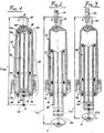
- Figure 1 is a view, along a longitudinal-section plane, of a first embodiment of a washing-assembly suspension means before being installed in a washing machine;
- Figure 2 is a view of the suspension means illustrated in Figure 1 in the state in which it is installed in a washing machine that is filled with both the washload and the water at the beginning of a wash cycle;
- Figure 3 is a view of the same suspension means illustrated in Figures 1 and 2 when the washing machine is going through the final spin-extraction phase of the wash cycle; and
- Figure 4 is a view, along the same longitudinal-section plane of Figure 1, of a second embodiment of the same suspension means as installed in a washing machine that is going through a wash cycle.
- As shown in the above cited Figures, a suspension means according to the present invention for suspending the washing assembly to the outer casing of a washing machine, substantially consists of a first and a second rigid member, which are generally indicated at 10 and 20, respectively, as well as two
helical springs - The first
rigid member 10 is a casing, which essentially consists of a first and a second cylindrically shapedpart female protrusions - In a first embodiment of the present invention (Figures 1 to 3), the first end portion 15 (ie. the upper one) of said
first part 11 of the firstrigid member 10 forms a seat in which the metal hingingpin 16 is retained for a first protrudingsteel hook 17 used for anchoring the suspension means on to the outer casing of the washing machine (as shown schematically with an eyelet M in Figures 2 and 3, for reasons of greater simplicity). - In a second embodiment of the present invention (Figure 4), the first end portion 15a of said
first part 11 of the firstrigid member 10 comprises a downward oriented appendix 16a on which afirst steel hook 17a is provided by overmoulding, whose protruding portion is used for anchoring the suspension means on to the outer casing of the washing machine (as shown schematically with an eyelet P in Figure 4 for reasons of greater simplicity). - The second end portion (ie. the lower one) of the same
first part 11 of the firstrigid member 10 is, in both above cited embodiments, open so as to enable the secondrigid element 20 to pass therethrough. - The first end portion (ie. the upper one) of said
second part 12 of the firstrigid member 10 is provided with the afore mentioned male-type protrusions 13 for joining with saidfirst part 11. - The second end portion (ie. the lower one) of the same
second part 12 of the firstrigid member 10 has acentral opening 18 that is delimited by anannular edge 19 against which an end portion of thesecond spring 40 is caused to abut, as this will be described in greater detail further on. - The second
rigid member 20, which is also made of injection-moulded plastic material, has a body in the shape of a goblet, or elongated bowl, and is arranged slidably inside the firstrigid member 10 through the opening 18. - The first end portion (ie. the upper one) of said second
rigid member 20 has acentral opening 21 defined by a downward facingannular edge 22, against which an end portion of thefirst spring 30 is caused to abut, as this will be described in greater detail further on. - In the first above cited embodiment (Figures 1 to 3), the second end portion 33 of said second
rigid member 20 forms a seat in which the metal hingingpin 26 is retained for a second protrudingsteel hook 27 for anchoring the suspension means on to the washing assembly of the washing machine (as shown schematically with an eyelet N in Figures 2 and 3 for reasons of greater simplicity). The suspension plane of thehook 27 may be perpendicular to the suspension plane of the hook 17 (as this is shown in the cited Figures), but it may also be different (eg. it may be the same), should the shape or geometric configuration of the washing assembly require it. In this first embodiment of the present invention, the body of the secondrigid member 20 is furthermore advantageously strengthened by means of at least a longitudinal rib 24 integrally moulded therewith. - In the second afore mentioned embodiment (Figure 4), the
second end portion 23a (ie. the lower one) of the secondrigid member 20 is provided by overmoulding with a second steel hook 27a for anchoring the suspension means on to the washing assembly of the washing machine (as shown schematically with an eyelet R in Figure 4 for reasons of greater simplicity). The suspension plane of the hook 27a may be the same as the suspension plane of thehook 17a (as this is shown in Figure 4), but it may also be different (eg. it may be perpendicular thereto), should the shape or geometric configuration of the washing assembly require it. - As this has already been pointed out above, the
helical springs annular edge 22 of the secondrigid member 20 and the oppositeannular edge 19 of saidsecond part 12 of the firstrigid member 10. Thesprings rigid member 20 inside the firstrigid member 10. This kind of arrangement is such as to ensure that thesprings - In the first above mentioned embodiment (Figures 1 to 3), the non-retained end portions of the
springs - In the second above cited embodiment (Figure 4), between the
springs annular spacer 50. In the case that the need arises or is felt for the extent of the stresses imparted by the washing assembly on the afore mentioned friction shock-absorbers to be reduced, this enables the radially inner and/or outer surface of thespacer 50 to be mounted with a certain interference on the secondrigid member 20 and thefirst part 11 of the firstrigid member 10, respectively. In other words, the elastic suspension means according to the present invention contributes in this case to dissipating the kinetic energy generated by the washing assembly. - From the above description, it can be inferred that the elastic suspension means according to the present invention has, from a construction point of view, some advantages that are not offered by the afore discussed prior-art solutions. The first one among such advantages lies in the fact that the device can actually be assembled very easily. By holding the
first part 11 of the firstrigid member 10 in a position which is turned upside down with respect to the one shown in the Figures, the secondrigid member 20 is first inserted thereinto from the top, followed by the twosprings second part 12 of the firstrigid member 10 is finally inserted by overcoming the reaction, or resistance, of the springs, up to the point in which thecurcumferential protrusions parts springs circumferential protrusions springs rigid members - For reasons of greater simplicity, the operation of the above illustrated suspension means is described below with reference only to the first cited embodiment of the present invention (Figures 1-3).
- From the illustration in Figure 1 it can be noticed that, before the suspension means is mounted in a washing machine, the distance between the centers of the two
hooks springs annular edges parts rigid member 10 to each other. - When the suspension means is on the contrary mounted in a washing machine, so that its
upper hook 17 is attached to the stationary structure M, while itslower hook 27 is attached to the tub N, ie. the washing assembly, and after the latter has been loaded with the clothes to be washed and the washing liquor, thesprings hooks hook 27, also a substantial length of the secondrigid member 20 protrudes downwards from the firstrigid member 10. The Applicant has found that the best operational results are obtained by so selecting aspring 40 as to make sure that, in these conditions, it is fully compressed (ie. "packed"), so that the suspension means is very rigid. As a result, the washing assembly remains substantially still, ie. does not move, with respect to the stationary structure of the washing machine, without any risk of bumps or shocks, during all of the phases of the washing process that are carried out at a low speed of the rotating drum (approx. 60 to 80 rpm). - When, according to the particular phase of the washing process, the washing machine then start to operate at a higher rotating speed of the drum (eg. 1500 rpm) to carry out a spin-extraction and water discharge phase, the
springs hooks - From an operative point of view, the suspension means according to the present invention has the advantage of not only making the washing assembly more or less rigid with respect to the stationary structure of the washing machine, depending on the various loading conditions of the washing assembly itself, but also of being practically self-adjusting.
- While the description given above is limited to embodiments of the present invention that, at this moment, may be considered as preferred ones, it will be appreciated that the scope of the present invention extends to also cover any other embodiment that may be developed by those skilled in the art from the teachings thereof. In particular, other elastically deformable means can be used instead of the two afore described helical springs, such as for instance a single spring comprising at least two lengths of different rigidity, so that one of them is fully compressed when the washing machine is fully loaded and operating at a low rotating speed of its drum. The same applies to the two
parts rigid member 10, which may be removably secured to each other with connection means differing from the snap-fittingones
Claims (3)
- Suspension means comprising a first and a second rigid member (10, 20) at least prevailingly made of plastics, each one of them having an end portion (15, 23; 15a, 23a) provided with attachment hooks (17, 27; 17a, 27a) for being in the same manner attached to either the stationary structure or the washing assembly of a rotating-drum washing machine, and comprising compression spring means (30, 40) which are adapted to vary the rigidity of the suspension of the washing assembly during the operation of the washing machine, said spring means (30, 40) being enclosed between the first one and the second one of said rigid members (10, 20) so as to ensure the mutual connection thereof, said first rigid member (10) essentially consisting of a casing with a first and a second part (11, 12) that are removably connected to each other, and further provided, at the second end portion thereof, with an opening (18) through which said second rigid member (20) is capable of sliding, having the end portions of said spring means (30, 40) retained between mutually opposing edges (19, 22) which are respectively provided on the second end portion of said first rigid member (10) and the first end portion of said second rigid member (20).
- Suspension means according to claim 1, where the said compression spring means consist of a series of at least two springs (30, 40), wherein at least one (40) of said springs is adapted to be in a state of substantially full compression when the washing assembly is loaded with the clothes to be washed and the washing liquor due to the fact that it has a different length and/or rigidity than the other spring (30).
- Suspension means according to claim 1 or 2, wherein said compression spring means (30, 40) consist of a single compression spring having at least two sections of a different length and/or rigidity.
Priority Applications (1)
| Application Number | Priority Date | Filing Date | Title |
|---|---|---|---|
| SI9830029T SI0896083T1 (en) | 1997-08-04 | 1998-06-23 | Improved elastic suspension means for the washing assembly of a washing machine |
Applications Claiming Priority (2)
| Application Number | Priority Date | Filing Date | Title |
|---|---|---|---|
| IT1997PN000035U IT243431Y1 (en) | 1997-08-04 | 1997-08-04 | PERFECT ELASTIC SUPPORT FOR THE WASHING GROUP OF A WASHING MACHINE |
| ITPN970035U | 1997-08-04 |
Publications (2)
| Publication Number | Publication Date |
|---|---|
| EP0896083A1 EP0896083A1 (en) | 1999-02-10 |
| EP0896083B1 true EP0896083B1 (en) | 2001-10-17 |
Family
ID=11395271
Family Applications (1)
| Application Number | Title | Priority Date | Filing Date |
|---|---|---|---|
| EP98111482A Expired - Lifetime EP0896083B1 (en) | 1997-08-04 | 1998-06-23 | Improved elastic suspension means for the washing assembly of a washing machine |
Country Status (6)
| Country | Link |
|---|---|
| EP (1) | EP0896083B1 (en) |
| DE (1) | DE69802050T2 (en) |
| ES (1) | ES2166121T3 (en) |
| IT (1) | IT243431Y1 (en) |
| PT (1) | PT896083E (en) |
| SI (1) | SI0896083T1 (en) |
Families Citing this family (1)
| Publication number | Priority date | Publication date | Assignee | Title |
|---|---|---|---|---|
| CN111485375B (en) * | 2019-01-29 | 2023-04-21 | 青岛海尔洗衣机有限公司 | Damping shock absorber, washing machine with same and control method |
Family Cites Families (5)
| Publication number | Priority date | Publication date | Assignee | Title |
|---|---|---|---|---|
| US3332523A (en) * | 1966-05-18 | 1967-07-25 | Bendix Corp | Telescopic frictional shock absorber |
| FR2605336B1 (en) * | 1986-10-17 | 1989-05-26 | Philips Ind Commerciale | SUSPENSION ARM FOR LAUNDRY WASHING MACHINE TANK AND LAUNDRY WASHING MACHINE THUS EQUIPPED. |
| JP2680695B2 (en) * | 1989-09-04 | 1997-11-19 | 三洋電機株式会社 | Dehydrator |
| DE4419870A1 (en) * | 1994-06-07 | 1995-12-14 | Suspa Compart Ag | Friction dampers, in particular for washing machines with a spin cycle |
| DE19615010A1 (en) * | 1996-04-16 | 1997-10-23 | Suspa Compart Ag | Friction dampers, in particular for washing machines with a spin cycle |
-
1997
- 1997-08-04 IT IT1997PN000035U patent/IT243431Y1/en active
-
1998
- 1998-06-23 PT PT98111482T patent/PT896083E/en unknown
- 1998-06-23 SI SI9830029T patent/SI0896083T1/en unknown
- 1998-06-23 DE DE69802050T patent/DE69802050T2/en not_active Expired - Lifetime
- 1998-06-23 EP EP98111482A patent/EP0896083B1/en not_active Expired - Lifetime
- 1998-06-23 ES ES98111482T patent/ES2166121T3/en not_active Expired - Lifetime
Also Published As
| Publication number | Publication date |
|---|---|
| DE69802050T2 (en) | 2002-06-06 |
| ES2166121T3 (en) | 2002-04-01 |
| PT896083E (en) | 2002-04-29 |
| ITPN970035U1 (en) | 1999-02-04 |
| SI0896083T1 (en) | 2001-12-31 |
| DE69802050D1 (en) | 2001-11-22 |
| IT243431Y1 (en) | 2002-03-04 |
| EP0896083A1 (en) | 1999-02-10 |
Similar Documents
| Publication | Publication Date | Title |
|---|---|---|
| US6397643B1 (en) | Suspension apparatus of washing machine | |
| US7549519B2 (en) | Free space damper | |
| US6264014B1 (en) | Friction damper for washing machines or the like | |
| WO2014158493A1 (en) | Non-cylindrical damping element suspension | |
| AU2008203385B2 (en) | Washing machine | |
| AU2008203386B2 (en) | Suspension apparatus for washing machine | |
| JPH1190086A (en) | Improvement of means for suspending washing assembly for electric washing machine | |
| EP0896083A1 (en) | Improved elastic suspension means for the washing assembly of a washing machine | |
| EP1679400A1 (en) | Drum of drum type washing machine | |
| EP0926290B1 (en) | Washing machine with improved anchoring means for the washing assembly | |
| US20040231373A1 (en) | Damper for washing machine | |
| EP0926291B1 (en) | Washing machine with improved anchoring means for the washing assembly | |
| KR102318757B1 (en) | Damping apparatus for Owashing machine | |
| KR101208494B1 (en) | drum type washing machine | |
| KR100304558B1 (en) | Damper for washing machine | |
| KR100987434B1 (en) | Tub for washing machine | |
| KR100730919B1 (en) | Reservoir fixing member for drum washing machine | |
| KR101186598B1 (en) | lift of drum type washing machine | |
| KR100691883B1 (en) | Damper of washing machine | |
| US20190186572A1 (en) | Integral rod and spring for a damper | |
| KR200145354Y1 (en) | A washer | |
| KR100781251B1 (en) | drum-type washing machine of tub formed with bracket as a unit | |
| US5893281A (en) | Tethering system for a clothes washing machine having a hung-strut suspension | |
| KR200172262Y1 (en) | A vibration decreasing structure for support bar of washing container | |
| KR200312878Y1 (en) | A damping device of spin dry chamber for double chamber type washing machine |
Legal Events
| Date | Code | Title | Description |
|---|---|---|---|
| PUAI | Public reference made under article 153(3) epc to a published international application that has entered the european phase |
Free format text: ORIGINAL CODE: 0009012 |
|
| AK | Designated contracting states |
Kind code of ref document: A1 Designated state(s): DE ES FR GB GR IT PT |
|
| AX | Request for extension of the european patent |
Free format text: AL;LT;LV;MK;RO;SI |
|
| 17P | Request for examination filed |
Effective date: 19990609 |
|
| AKX | Designation fees paid |
Free format text: DE ES FR GB IT |
|
| AXX | Extension fees paid |
Free format text: SI PAYMENT 19990609 |
|
| RBV | Designated contracting states (corrected) |
Designated state(s): DE ES FR GB GR IT PT |
|
| 17Q | First examination report despatched |
Effective date: 20000224 |
|
| GRAG | Despatch of communication of intention to grant |
Free format text: ORIGINAL CODE: EPIDOS AGRA |
|
| GRAG | Despatch of communication of intention to grant |
Free format text: ORIGINAL CODE: EPIDOS AGRA |
|
| GRAH | Despatch of communication of intention to grant a patent |
Free format text: ORIGINAL CODE: EPIDOS IGRA |
|
| ITF | It: translation for a ep patent filed | ||
| GRAH | Despatch of communication of intention to grant a patent |
Free format text: ORIGINAL CODE: EPIDOS IGRA |
|
| GRAA | (expected) grant |
Free format text: ORIGINAL CODE: 0009210 |
|
| AK | Designated contracting states |
Kind code of ref document: B1 Designated state(s): DE ES FR GB GR IT PT |
|
| AX | Request for extension of the european patent |
Free format text: SI PAYMENT 19990609 |
|
| REF | Corresponds to: |
Ref document number: 69802050 Country of ref document: DE Date of ref document: 20011122 |
|
| REG | Reference to a national code |
Ref country code: GB Ref legal event code: IF02 |
|
| REG | Reference to a national code |
Ref country code: GR Ref legal event code: EP Ref document number: 20010401989 Country of ref document: GR |
|
| ET | Fr: translation filed | ||
| REG | Reference to a national code |
Ref country code: ES Ref legal event code: FG2A Ref document number: 2166121 Country of ref document: ES Kind code of ref document: T3 |
|
| REG | Reference to a national code |
Ref country code: PT Ref legal event code: SC4A Free format text: AVAILABILITY OF NATIONAL TRANSLATION Effective date: 20020111 |
|
| PLBE | No opposition filed within time limit |
Free format text: ORIGINAL CODE: 0009261 |
|
| STAA | Information on the status of an ep patent application or granted ep patent |
Free format text: STATUS: NO OPPOSITION FILED WITHIN TIME LIMIT |
|
| 26N | No opposition filed | ||
| REG | Reference to a national code |
Ref country code: SI Ref legal event code: IF |
|
| PGFP | Annual fee paid to national office [announced via postgrant information from national office to epo] |
Ref country code: PT Payment date: 20080519 Year of fee payment: 11 |
|
| PGFP | Annual fee paid to national office [announced via postgrant information from national office to epo] |
Ref country code: GR Payment date: 20080514 Year of fee payment: 11 |
|
| REG | Reference to a national code |
Ref country code: PT Ref legal event code: MM4A Free format text: LAPSE DUE TO NON-PAYMENT OF FEES Effective date: 20091223 |
|
| PG25 | Lapsed in a contracting state [announced via postgrant information from national office to epo] |
Ref country code: PT Free format text: LAPSE BECAUSE OF NON-PAYMENT OF DUE FEES Effective date: 20091223 |
|
| REG | Reference to a national code |
Ref country code: SI Ref legal event code: KO00 Effective date: 20100216 |
|
| PG25 | Lapsed in a contracting state [announced via postgrant information from national office to epo] |
Ref country code: GR Free format text: LAPSE BECAUSE OF NON-PAYMENT OF DUE FEES Effective date: 20100107 |
|
| PGFP | Annual fee paid to national office [announced via postgrant information from national office to epo] |
Ref country code: FR Payment date: 20110630 Year of fee payment: 14 Ref country code: ES Payment date: 20110616 Year of fee payment: 14 |
|
| PGFP | Annual fee paid to national office [announced via postgrant information from national office to epo] |
Ref country code: GB Payment date: 20110620 Year of fee payment: 14 |
|
| PGFP | Annual fee paid to national office [announced via postgrant information from national office to epo] |
Ref country code: DE Payment date: 20110622 Year of fee payment: 14 |
|
| PGFP | Annual fee paid to national office [announced via postgrant information from national office to epo] |
Ref country code: IT Payment date: 20110628 Year of fee payment: 14 |
|
| GBPC | Gb: european patent ceased through non-payment of renewal fee |
Effective date: 20120623 |
|
| PG25 | Lapsed in a contracting state [announced via postgrant information from national office to epo] |
Ref country code: IT Free format text: LAPSE BECAUSE OF NON-PAYMENT OF DUE FEES Effective date: 20120623 |
|
| REG | Reference to a national code |
Ref country code: FR Ref legal event code: ST Effective date: 20130228 |
|
| PG25 | Lapsed in a contracting state [announced via postgrant information from national office to epo] |
Ref country code: GB Free format text: LAPSE BECAUSE OF NON-PAYMENT OF DUE FEES Effective date: 20120623 Ref country code: FR Free format text: LAPSE BECAUSE OF NON-PAYMENT OF DUE FEES Effective date: 20120702 Ref country code: DE Free format text: LAPSE BECAUSE OF NON-PAYMENT OF DUE FEES Effective date: 20130101 |
|
| REG | Reference to a national code |
Ref country code: DE Ref legal event code: R119 Ref document number: 69802050 Country of ref document: DE Effective date: 20130101 |
|
| REG | Reference to a national code |
Ref country code: ES Ref legal event code: FD2A Effective date: 20131022 |
|
| PG25 | Lapsed in a contracting state [announced via postgrant information from national office to epo] |
Ref country code: ES Free format text: LAPSE BECAUSE OF NON-PAYMENT OF DUE FEES Effective date: 20120624 |