EP0895249B1 - Remote-controlled-lid type pneumatic vessel for powder - Google Patents
Remote-controlled-lid type pneumatic vessel for powder Download PDFInfo
- Publication number
- EP0895249B1 EP0895249B1 EP98305912A EP98305912A EP0895249B1 EP 0895249 B1 EP0895249 B1 EP 0895249B1 EP 98305912 A EP98305912 A EP 98305912A EP 98305912 A EP98305912 A EP 98305912A EP 0895249 B1 EP0895249 B1 EP 0895249B1
- Authority
- EP
- European Patent Office
- Prior art keywords
- vessel
- lid
- aperture
- remote
- powder
- Prior art date
- Legal status (The legal status is an assumption and is not a legal conclusion. Google has not performed a legal analysis and makes no representation as to the accuracy of the status listed.)
- Expired - Lifetime
Links
Images
Classifications
-
- G—PHYSICS
- G21—NUCLEAR PHYSICS; NUCLEAR ENGINEERING
- G21C—NUCLEAR REACTORS
- G21C21/00—Apparatus or processes specially adapted to the manufacture of reactors or parts thereof
- G21C21/02—Manufacture of fuel elements or breeder elements contained in non-active casings
-
- G—PHYSICS
- G21—NUCLEAR PHYSICS; NUCLEAR ENGINEERING
- G21F—PROTECTION AGAINST X-RADIATION, GAMMA RADIATION, CORPUSCULAR RADIATION OR PARTICLE BOMBARDMENT; TREATING RADIOACTIVELY CONTAMINATED MATERIAL; DECONTAMINATION ARRANGEMENTS THEREFOR
- G21F5/00—Transportable or portable shielded containers
- G21F5/06—Details of, or accessories to, the containers
- G21F5/12—Closures for containers; Sealing arrangements
-
- Y—GENERAL TAGGING OF NEW TECHNOLOGICAL DEVELOPMENTS; GENERAL TAGGING OF CROSS-SECTIONAL TECHNOLOGIES SPANNING OVER SEVERAL SECTIONS OF THE IPC; TECHNICAL SUBJECTS COVERED BY FORMER USPC CROSS-REFERENCE ART COLLECTIONS [XRACs] AND DIGESTS
- Y02—TECHNOLOGIES OR APPLICATIONS FOR MITIGATION OR ADAPTATION AGAINST CLIMATE CHANGE
- Y02E—REDUCTION OF GREENHOUSE GAS [GHG] EMISSIONS, RELATED TO ENERGY GENERATION, TRANSMISSION OR DISTRIBUTION
- Y02E30/00—Energy generation of nuclear origin
- Y02E30/30—Nuclear fission reactors
Definitions
- the present invention relates to a remote-controlled-lid type pneumatic vessel for powder used to carry a powdered nuclear fuel substance to be handled under a confined state or powder requiring scattering prevention by a pneumatic system. It is possible to store any of grains, tablets, pellets, slurries, and liquid in addition to powder.
- a conventional pneumatic vessel body "a” uses a stainless-steel vessel.
- the lid is operated through remote control in order to reduce radioactive exposure, and thus the lid can be easily removed through remote control. Therefore, the pneumatic vessel body “a” cannot be pneumatically carried independently, so that the vessel body “a” is pneumatically carried while stored in a strong aluminum outer vessel “b” having the sectional structure shown in Fig. 9.
- a remote-controlled-lid type pneumatic vessel for powder comprising a vessel provided with an aperture for storing powder and a lid to be fitted in the aperture; wherein an upper edge extending in the circumferential direction, a fixed ring for holding the lid at a predetermined position of the vessel, and at lease one non-slip ring contacting the inside wall of the aperture are formed in that order on the outer-peripheral wall of the lid starting at the top of the outer-peripheral wall thereof, a catching groove fitted to the fixed ring of the lid is formed on the inside wall of the aperture of the vessel, and a predetermined clearance is formed between the end edge of the aperture and the upper edge of the lid while the fixed ring of the lid is fitted to the catching groove.
- a vessel 1 and a lid 2 are both made of a flammable material such as, for example, reinforced polyethylene. Therefore, the pneumatic vessel 1 becomes inexpensive compared to a conventional one made of stainless-steel and it can be incinerated for volume reduction as a radioactive waste. Moreover, a vessel identification number can be inexpensively provided to the pneumatic vessel by a label.
- an upper edge 21 extending in the circumferential direction, a fixed ring 22, and three non-slip rings 23 are formed on the outer-peripheral wall of the lid 2 in that order starting at the top thereof.
- a catching groove 11 fitted to the fixed ring 22 of the lid 2 is provided in the inside wall of the aperture of the vessel 1 and the position of the catching groove 11 is selected so that a predetermined clearance is formed between the end edge 12 of the aperture of the vessel 1 and the upper edge 21 of the lid 2 while the fixed ring 22 of the lid 2 is fitted to the catching groove 11.
- the inside wall of the vessel 1 is formed so that the inside diameter of the vessel 1 gradually decreases toward the bottom and the lower non-slip ring 23 more strongly contacts the inside wall of the aperture of the vessel 1.
- the lid 2 While the lid 2 is fixed, the fixed ring 22 is fitted to the catching groove 11 and the non-slip rings 23 are pressed against the inside wall of the aperture. Therefore, the powder in the vessel 1 is kept confined and the lid 2 can be also securely fixed to the vessel 1. Therefore, the lid 2 will not be removed from the vessel 1 while the vessel 1 is pneumatically carried.
- the pneumatic vessel of the present invention it is possible to perform pneumatic carrying only by the pneumatic vessel in the direction of the front or rear side without using a conventional outer vessel.
- a method for opening the lid of the pneumatic vessel is described below.
- the predetermined clearance is formed between the end edge 12 of the aperture of the vessel 1 and the upper edge 21 of the lid 2 as shown in Fig. 5. Therefore, to remove the lid 2, it is possible to easily remove the lid 2 even through remote control by parallelly inserting a jig 3 between the upper end 21 of the lid 2 and the end edge 12 of the aperture of the vessel 1 as shown in Figs. 6A and 6B.
- the front top face of the jig 3 is tapered toward the tip end thereof.
- Fig. 6A is a drawing viewed from the upper side
- Fig. 6B is a drawing viewed from the lateral side.
- the inside wall of the vessel 1 is formed so that the inside diameter of the vessel 1 decreases gradually toward the bottom. More specifically, as shown in Fig. 7, because the inside diameter Y of the bottom is made smaller than the inside diameter X of a portion near the aperture so that the tilt angle of the inside wall 13 of the vessel 1 increases, it is possible to easily take out the powder from the vessel 1 without significantly tilting the vessel 1.
- the present invention makes it possible to obtain the following specific advantages.
Landscapes
- Engineering & Computer Science (AREA)
- Physics & Mathematics (AREA)
- General Engineering & Computer Science (AREA)
- High Energy & Nuclear Physics (AREA)
- Manufacturing & Machinery (AREA)
- Plasma & Fusion (AREA)
- Closures For Containers (AREA)
Description
- The present invention relates to a remote-controlled-lid type pneumatic vessel for powder used to carry a powdered nuclear fuel substance to be handled under a confined state or powder requiring scattering prevention by a pneumatic system. It is possible to store any of grains, tablets, pellets, slurries, and liquid in addition to powder.
- In the process for manufacturing nuclear fuel pellets, it is necessary to perform various analytic inspections in the middle of the manufacturing process in order to confirm the property of a powdered nuclear fuel substance serving as a raw material.
- It is necessary to handle the nuclear fuel substance which must undergo analytic inspections under a confined state. Therefore, manufacturing equipment and analyzing equipment are connected with each other by a stainless-steel tube and the substance is carried in the tube by the pneumatic system. That is, the powdered nuclear fuel substance is stored in a pneumatic vessel and this vessel is carried in the stainless-steel tube by using an air pressure difference.
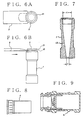
- As shown in Fig. 8, a conventional pneumatic vessel body "a" uses a stainless-steel vessel. In the case of the pneumatic vessel body "a", the lid is operated through remote control in order to reduce radioactive exposure, and thus the lid can be easily removed through remote control. Therefore, the pneumatic vessel body "a" cannot be pneumatically carried independently, so that the vessel body "a" is pneumatically carried while stored in a strong aluminum outer vessel "b" having the sectional structure shown in Fig. 9.
- In the conventional pneumatic vessel described above, the following problems occur.
- (1) Because the lid is constituted so as to be easily removed, it is impossible to pneumatically carry only the pneumatic vessel and therefore, the outer vessel is required.
- (2) Because the outer vessel uses a complex locking mechanism so that the lid is not removed while pneumatically carried, the lid of the outer vessel cannot be operated through remote control but it must be manually operated. Therefore, when storing the pneumatic vessel body in the outer vessel, the operation efficiency is lowered because it is necessary to protect an operator from radiation exposure. Moreover, the locking mechanism may not be securely locked when power is caught in the mechanism. In this case, the operation efficiency is further lowered.
- (3) Because the pneumatic vessel is made of remote-controllable stainless steel and moreover, the identification number of the vessel is formed with engraving, the price including its machining cost increases.
- (4) The pneumatic vessel made of stainless steel is recycled by cleaning it because the volume reduction of the vessel required for radioactive waste disposal is not available. However, in the case of insufficient cleaning, different types of nuclear fuel substances are mixed to cause an analysis error.
- (5) Moreover, because the identification number of the outer vessel made of aluminum is formed with engraving similarly to the case of the pneumatic vessel body, the price of the outer vessel is also increased.
-
- It is an object of the present invention to provide a remote-controlled-lid type pneumatic vessel for powder which can be used as a single unit and is superior to a conventional double-structure pneumatic vessel in airtightness, whose lid can be operated through remote control, which is not recycled after being cleaned because it is made of an inexpensive material, and which can be incinerated for volume reduction as a radioactive waste.
- According to the present invention, there is provided a remote-controlled-lid type pneumatic vessel for powder comprising a vessel provided with an aperture for storing powder and a lid to be fitted in the aperture; wherein an upper edge extending in the circumferential direction, a fixed ring for holding the lid at a predetermined position of the vessel, and at lease one non-slip ring contacting the inside wall of the aperture are formed in that order on the outer-peripheral wall of the lid starting at the top of the outer-peripheral wall thereof, a catching groove fitted to the fixed ring of the lid is formed on the inside wall of the aperture of the vessel, and a predetermined clearance is formed between the end edge of the aperture and the upper edge of the lid while the fixed ring of the lid is fitted to the catching groove.
- Preferred embodiments of the present invention will now be described by way of example with reference to the accompanying drawings, in which:
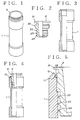
- Figure 1 is a perspective view showing the appearance of the remote-controlled-lid type pneumatic vessel for powder of an embodiment of the present invention;
- Figure 2 is a local sectional view showing the structure of a lid;
- Figure 3 is a local sectional view showing the structure of a vessel;
- Figure 4 is a local sectional view showing the structure of a vessel to which a lid is fitted;
- Figure 5 is an enlarged sectional view of the aperture of a vessel to which a lid is fitted;
- Figures 6A and 6B are illustrations for explaining a method for removing a lid;
- Figure 7 is a sectional view for explaining the shape of the inside wall of a vessel;
- Figure 8 is a front view showing the structure of a conventional pneumatic vessel body; and
- Figure 9 is a sectional view showing the structure of a conventional outer vessel.
-
- Referring to Figs. 1 to 5, a
vessel 1 and alid 2 are both made of a flammable material such as, for example, reinforced polyethylene. Therefore, thepneumatic vessel 1 becomes inexpensive compared to a conventional one made of stainless-steel and it can be incinerated for volume reduction as a radioactive waste. Moreover, a vessel identification number can be inexpensively provided to the pneumatic vessel by a label. - As shown in Fig. 2, an
upper edge 21 extending in the circumferential direction, afixed ring 22, and threenon-slip rings 23 are formed on the outer-peripheral wall of thelid 2 in that order starting at the top thereof. - Moreover, as shown in Fig. 5, a
catching groove 11 fitted to thefixed ring 22 of thelid 2 is provided in the inside wall of the aperture of thevessel 1 and the position of thecatching groove 11 is selected so that a predetermined clearance is formed between theend edge 12 of the aperture of thevessel 1 and theupper edge 21 of thelid 2 while thefixed ring 22 of thelid 2 is fitted to thecatching groove 11. Moreover, the inside wall of thevessel 1 is formed so that the inside diameter of thevessel 1 gradually decreases toward the bottom and thelower non-slip ring 23 more strongly contacts the inside wall of the aperture of thevessel 1. - In the case of this embodiment constituted as described above, by storing powder in the
vessel 1 and thereafter inserting thelid 2 into the aperture of thevessel 1, thelid 2 moves downward while thenon-slip rings 23 of thelid 2 are pressed against the inside wall of the aperture. Moreover, when thelid 2 moves downward by a predetermined distance, thefixed ring 22 of thelid 2 is fitted to thecatching groove 11 of the aperture and thelid 2 is fixed to thevessel 1. - While the
lid 2 is fixed, thefixed ring 22 is fitted to thecatching groove 11 and thenon-slip rings 23 are pressed against the inside wall of the aperture. Therefore, the powder in thevessel 1 is kept confined and thelid 2 can be also securely fixed to thevessel 1. Therefore, thelid 2 will not be removed from thevessel 1 while thevessel 1 is pneumatically carried. - Thus, by using the pneumatic vessel of the present invention, it is possible to perform pneumatic carrying only by the pneumatic vessel in the direction of the front or rear side without using a conventional outer vessel.
- Then, a method for opening the lid of the pneumatic vessel is described below. As previously described, while the
lid 2 is fixed to the vessel 1 (while thelid 2 is plugged), the predetermined clearance is formed between theend edge 12 of the aperture of thevessel 1 and theupper edge 21 of thelid 2 as shown in Fig. 5. Therefore, to remove thelid 2, it is possible to easily remove thelid 2 even through remote control by parallelly inserting ajig 3 between theupper end 21 of thelid 2 and theend edge 12 of the aperture of thevessel 1 as shown in Figs. 6A and 6B. The front top face of thejig 3 is tapered toward the tip end thereof. Fig. 6A is a drawing viewed from the upper side and Fig. 6B is a drawing viewed from the lateral side. - As previously described, the inside wall of the
vessel 1 is formed so that the inside diameter of thevessel 1 decreases gradually toward the bottom. More specifically, as shown in Fig. 7, because the inside diameter Y of the bottom is made smaller than the inside diameter X of a portion near the aperture so that the tilt angle of theinside wall 13 of thevessel 1 increases, it is possible to easily take out the powder from thevessel 1 without significantly tilting thevessel 1. - As described above, the present invention makes it possible to obtain the following specific advantages.
- (1) Because a lid can be operated through remote control and moreover, the lid can be securely fixed, it is possible to pneumatically carry a nuclear fuel substance using only a pneumatic vessel without using an outer vessel.
- (2) Because no outer vessel is used, it is unnecessary to manually store a pneumatic vessel in an outer vessel and therefore, the operation efficiency is improved and radiation exposure can be reduced.
- (3) By using reinforced polyethylene as the material of a vessel and a lid and identifying a vessel number by a label, it is possible to reduce the vessel cost.
- (4) Because the material of a pneumatic vessel may be inflammable such as reinforced polyethylene, it is possible to incinerate a radioactive waste to reduce the volume of the waste without recycling the waste after cleaning.
- (5) As an object to be put in a pneumatic vessel, any of grains, tablets, pellets, slurries, and liquid in addition to powder can be used. Moreover, the pneumatic vessel can be used as a sample vessel.
-
Claims (4)
- A remote-controlled-lid type pneumatic vessel for powder comprising a vessel (1) provided with an aperture for storing powder and a lid (2) to be fitted in the aperture; characterised in thatan upper edge (21) extending in the circumferential direction, a fixed ring (22) for holding the lid at a predetermined position of the vessel, and at least one non-slip ring (23) contacting the inside wall of the aperture are formed in that order on the outer-peripheral wall of the lid (2) starting at the top of the outer-peripheral wall thereof,a catching groove (11) fitted to the fixed ring (22) of the lid is formed on the inside wall of the aperture of the vessel (1), anda predetermined clearance is formed between the end edge (12) of the aperture and the upper edge (21) of the lid while the fixed ring (22) of the lid is fitted to the catching groove (11).
- The remote-controlled-lid type pneumatic vessel for powder according to claim 1, wherein the inside wall of the vessel (1) is formed so that the inside diameter of the vessel gradually decreases toward the bottom of the vessel.
- The remote-controlled-lid type pneumatic vessel for powder according to claim 2, wherein a plurality of the non-slip rings (23) are formed in the longitudinal direction of the lid (2) so that the lower non-slip ring more contacts the inside wall of the vessel (1).
- The remote-controlled-lid type pneumatic vessel for powder according to claim 1, wherein the vessel (1) and the lid (2) are both made of an inflammable material so that they can be incinerated.
Applications Claiming Priority (3)
| Application Number | Priority Date | Filing Date | Title |
|---|---|---|---|
| JP9215519A JPH1144792A (en) | 1997-07-28 | 1997-07-28 | Remote lid openable pneumatic container for powder |
| JP215519/97 | 1997-07-28 | ||
| JP21551997 | 1997-07-28 |
Publications (2)
| Publication Number | Publication Date |
|---|---|
| EP0895249A1 EP0895249A1 (en) | 1999-02-03 |
| EP0895249B1 true EP0895249B1 (en) | 2001-12-05 |
Family
ID=16673767
Family Applications (1)
| Application Number | Title | Priority Date | Filing Date |
|---|---|---|---|
| EP98305912A Expired - Lifetime EP0895249B1 (en) | 1997-07-28 | 1998-07-24 | Remote-controlled-lid type pneumatic vessel for powder |
Country Status (3)
| Country | Link |
|---|---|
| EP (1) | EP0895249B1 (en) |
| JP (1) | JPH1144792A (en) |
| DE (1) | DE69802751T2 (en) |
Families Citing this family (4)
| Publication number | Priority date | Publication date | Assignee | Title |
|---|---|---|---|---|
| JP5005487B2 (en) * | 2007-10-02 | 2012-08-22 | 金森化学工業株式会社 | Transport container |
| DE102008031736B3 (en) * | 2008-07-04 | 2009-07-23 | Protechna S.A. | screw |
| JP5219887B2 (en) * | 2009-02-27 | 2013-06-26 | 株式会社コクゴ | Liquid sample transfer device |
| CN104058253B (en) * | 2014-06-29 | 2016-01-20 | 金双蕾 | A kind of fuel supply system |
Family Cites Families (8)
| Publication number | Priority date | Publication date | Assignee | Title |
|---|---|---|---|---|
| US3840155A (en) * | 1972-04-18 | 1974-10-08 | Boardman Co | Nuclear fuel handling powder container |
| US4347943A (en) * | 1981-04-14 | 1982-09-07 | National Plastics Limited | Containers |
| DE3230039C2 (en) * | 1982-08-12 | 1984-11-08 | Alkem Gmbh, 6450 Hanau | Apparatus for treating a granular substance, in particular nuclear reactor fuel in powder form, and a method for operating the apparatus |
| DE3516837A1 (en) * | 1985-05-10 | 1986-11-13 | Siempelkamp Gießerei GmbH & Co, 4150 Krefeld | Shipping cask and/or storage container for radioactive substances |
| DE3545494A1 (en) * | 1985-12-20 | 1987-07-02 | Alkem Gmbh | Conveyor device for nuclear fuel powder |
| DE8619340U1 (en) * | 1986-07-18 | 1987-08-20 | Siemens AG, 1000 Berlin und 8000 München | Container especially for a radioactive and/or toxic substance |
| DE3923260A1 (en) * | 1989-07-14 | 1991-01-24 | Noell Gmbh | LOCK FOR RADIOACTIVE OR TOXIC CONTAINERS |
| US5727707A (en) * | 1996-09-25 | 1998-03-17 | Nuclear Filter Technology, Inc. | Hepa filtered storage canisters |
-
1997
- 1997-07-28 JP JP9215519A patent/JPH1144792A/en active Pending
-
1998
- 1998-07-24 DE DE69802751T patent/DE69802751T2/en not_active Expired - Lifetime
- 1998-07-24 EP EP98305912A patent/EP0895249B1/en not_active Expired - Lifetime
Also Published As
| Publication number | Publication date |
|---|---|
| DE69802751D1 (en) | 2002-01-17 |
| DE69802751T2 (en) | 2002-08-08 |
| JPH1144792A (en) | 1999-02-16 |
| EP0895249A1 (en) | 1999-02-03 |
Similar Documents
| Publication | Publication Date | Title |
|---|---|---|
| JP2524317B2 (en) | Transport container for enriched uranium | |
| RU2404465C2 (en) | Cover for loading nuclear reactor fuel assembly into container, gripping device and method of loading | |
| US5033520A (en) | Refuse disposal container | |
| US5154308A (en) | Detachable cover and drum liner for storage and transport of controlled materials | |
| JP6695948B2 (en) | Radioactive waste container | |
| US5727707A (en) | Hepa filtered storage canisters | |
| US6543654B1 (en) | Device for emptying containers filled with liquids | |
| EP0895249A1 (en) | Remote-controlled-lid type pneumatic vessel for powder | |
| US5225114A (en) | Multipurpose container for low-level radioactive waste | |
| EP3334680B1 (en) | Puncturing device for aerosol containers | |
| US5255492A (en) | Detachable cover and drum liner for storage and transport of controlled materials | |
| US5284998A (en) | Drum and process for handling drum liners | |
| CN110606269A (en) | Containers and container assemblies for containing radioactive waste | |
| CA2175995C (en) | Protective bottle jacket | |
| US5574759A (en) | Method for dismantling bulky parts of pressure-vessel fittings of a nuclear plant and for receiving the dismantled parts | |
| US5628342A (en) | Propellant transporting device | |
| CN119092171A (en) | A radioactive highly corrosive toxic liquid transfer device and transfer method | |
| EP1325501B1 (en) | Radiographic camera | |
| US12459729B2 (en) | Device for storing and transporting bulk material, in particular pharmaceutical bulk material, as well as a method for filling a device of this kind with said bulk material and for emptying a device filled with said bulk material | |
| US5353951A (en) | Serviceable storage and transport container | |
| EP0650056B1 (en) | System for automatic analyses | |
| KR102645619B1 (en) | radioactive contamination measuring system and method for compressing radioactive waste filters | |
| WO2002051236A2 (en) | Device for the bulk supply of polymers | |
| JP2713644B2 (en) | Post-test preparation of irradiated reactor fuel assemblies | |
| JPH05172995A (en) | Compressing treatment of radioactive waste and device thereof |
Legal Events
| Date | Code | Title | Description |
|---|---|---|---|
| PUAI | Public reference made under article 153(3) epc to a published international application that has entered the european phase |
Free format text: ORIGINAL CODE: 0009012 |
|
| AK | Designated contracting states |
Kind code of ref document: A1 Designated state(s): DE FR GB |
|
| AX | Request for extension of the european patent |
Free format text: AL;LT;LV;MK;RO;SI |
|
| 17P | Request for examination filed |
Effective date: 19990224 |
|
| RAP1 | Party data changed (applicant data changed or rights of an application transferred) |
Owner name: JAPAN NUCLEAR CYCLE DEVELOPMENT INSTITUTE |
|
| AKX | Designation fees paid |
Free format text: DE FR GB |
|
| RIC1 | Information provided on ipc code assigned before grant |
Free format text: 7B 65D 43/06 A, 7G 21F 5/008 B, 7G 21F 5/12 B |
|
| GRAG | Despatch of communication of intention to grant |
Free format text: ORIGINAL CODE: EPIDOS AGRA |
|
| 17Q | First examination report despatched |
Effective date: 20010222 |
|
| GRAG | Despatch of communication of intention to grant |
Free format text: ORIGINAL CODE: EPIDOS AGRA |
|
| GRAH | Despatch of communication of intention to grant a patent |
Free format text: ORIGINAL CODE: EPIDOS IGRA |
|
| GRAH | Despatch of communication of intention to grant a patent |
Free format text: ORIGINAL CODE: EPIDOS IGRA |
|
| GRAA | (expected) grant |
Free format text: ORIGINAL CODE: 0009210 |
|
| AK | Designated contracting states |
Kind code of ref document: B1 Designated state(s): DE FR GB |
|
| REG | Reference to a national code |
Ref country code: GB Ref legal event code: IF02 |
|
| REF | Corresponds to: |
Ref document number: 69802751 Country of ref document: DE Date of ref document: 20020117 |
|
| ET | Fr: translation filed | ||
| PLBE | No opposition filed within time limit |
Free format text: ORIGINAL CODE: 0009261 |
|
| STAA | Information on the status of an ep patent application or granted ep patent |
Free format text: STATUS: NO OPPOSITION FILED WITHIN TIME LIMIT |
|
| 26N | No opposition filed | ||
| PGFP | Annual fee paid to national office [announced via postgrant information from national office to epo] |
Ref country code: FR Payment date: 20110727 Year of fee payment: 14 |
|
| PGFP | Annual fee paid to national office [announced via postgrant information from national office to epo] |
Ref country code: GB Payment date: 20110720 Year of fee payment: 14 Ref country code: DE Payment date: 20110720 Year of fee payment: 14 |
|
| GBPC | Gb: european patent ceased through non-payment of renewal fee |
Effective date: 20120724 |
|
| REG | Reference to a national code |
Ref country code: FR Ref legal event code: ST Effective date: 20130329 |
|
| PG25 | Lapsed in a contracting state [announced via postgrant information from national office to epo] |
Ref country code: GB Free format text: LAPSE BECAUSE OF NON-PAYMENT OF DUE FEES Effective date: 20120724 Ref country code: DE Free format text: LAPSE BECAUSE OF NON-PAYMENT OF DUE FEES Effective date: 20130201 Ref country code: FR Free format text: LAPSE BECAUSE OF NON-PAYMENT OF DUE FEES Effective date: 20120731 |
|
| REG | Reference to a national code |
Ref country code: DE Ref legal event code: R119 Ref document number: 69802751 Country of ref document: DE Effective date: 20130201 |