EP0894901A2 - Control for hydraulically operated construction machine having multiple tandem articulated members - Google Patents
Control for hydraulically operated construction machine having multiple tandem articulated members Download PDFInfo
- Publication number
- EP0894901A2 EP0894901A2 EP98114208A EP98114208A EP0894901A2 EP 0894901 A2 EP0894901 A2 EP 0894901A2 EP 98114208 A EP98114208 A EP 98114208A EP 98114208 A EP98114208 A EP 98114208A EP 0894901 A2 EP0894901 A2 EP 0894901A2
- Authority
- EP
- European Patent Office
- Prior art keywords
- members
- movement
- signal
- hydraulic
- construction machine
- Prior art date
- Legal status (The legal status is an assumption and is not a legal conclusion. Google has not performed a legal analysis and makes no representation as to the accuracy of the status listed.)
- Withdrawn
Links
Images



Classifications
-
- E—FIXED CONSTRUCTIONS
- E02—HYDRAULIC ENGINEERING; FOUNDATIONS; SOIL SHIFTING
- E02F—DREDGING; SOIL-SHIFTING
- E02F9/00—Component parts of dredgers or soil-shifting machines, not restricted to one of the kinds covered by groups E02F3/00 - E02F7/00
- E02F9/20—Drives; Control devices
- E02F9/2025—Particular purposes of control systems not otherwise provided for
-
- E—FIXED CONSTRUCTIONS
- E02—HYDRAULIC ENGINEERING; FOUNDATIONS; SOIL SHIFTING
- E02F—DREDGING; SOIL-SHIFTING
- E02F3/00—Dredgers; Soil-shifting machines
- E02F3/04—Dredgers; Soil-shifting machines mechanically-driven
- E02F3/28—Dredgers; Soil-shifting machines mechanically-driven with digging tools mounted on a dipper- or bucket-arm, i.e. there is either one arm or a pair of arms, e.g. dippers, buckets
- E02F3/36—Component parts
- E02F3/42—Drives for dippers, buckets, dipper-arms or bucket-arms
- E02F3/43—Control of dipper or bucket position; Control of sequence of drive operations
- E02F3/435—Control of dipper or bucket position; Control of sequence of drive operations for dipper-arms, backhoes or the like
- E02F3/437—Control of dipper or bucket position; Control of sequence of drive operations for dipper-arms, backhoes or the like providing automatic sequences of movements, e.g. linear excavation, keeping dipper angle constant
-
- Y—GENERAL TAGGING OF NEW TECHNOLOGICAL DEVELOPMENTS; GENERAL TAGGING OF CROSS-SECTIONAL TECHNOLOGIES SPANNING OVER SEVERAL SECTIONS OF THE IPC; TECHNICAL SUBJECTS COVERED BY FORMER USPC CROSS-REFERENCE ART COLLECTIONS [XRACs] AND DIGESTS
- Y10—TECHNICAL SUBJECTS COVERED BY FORMER USPC
- Y10S—TECHNICAL SUBJECTS COVERED BY FORMER USPC CROSS-REFERENCE ART COLLECTIONS [XRACs] AND DIGESTS
- Y10S37/00—Excavating
- Y10S37/907—Automatic leveling excavators
Definitions
- This invention relates generally to hydraulically operated machines and, in particular, to such machines having multiple tandem articulated members which move in unison in order to produce a desired movement of one of the members.
- the invention is particularly adapted for use with hydraulically controlled construction equipment, such as hydraulic excavators.
- one form of control is to provide the operator with manual control of one member such that the member moves in a manner desired by the operator, with other members of the construction equipment automatically controlled, such as by a computer control, in a manner which compensates for the movement of the member manually controlled by the operator.
- a computer control such as by a computer control
- the present invention provides an apparatus and method for controlling a hydraulically operated construction machine having a plurality of tandem articulated members which move in a particular pattern wherein movement of one of the members is controlled in response to movement of a second one of the members.
- anticipated future movement of the second member is determined and the first member is controlled as a function at least of the anticipated future movement of the second member.
- the anticipated future movement is determined by measuring actual time delay between movement of the first and second members. This allows the amount of compensation provided for delays to be precise.
- the actual time delay is measured at the beginning of each start from rest operation of both the manually operated member and the automatically operated member and is utilized at each successive operation of the members.
- an operator-controlled actuator or joystick
- a user input selection of a command level is received by a control.
- the motion-producing system is operated as a function of the operation of the joystick by the operator and by the value of the command level selected by the user. This allows the operator to select the degree of control afforded the operator.
- maximum compensation is provided and the operator is essentially only able to determine the direction of movement of the member.
- a command level at an opposite end of the range of command levels provides more proportionate control wherein the operator is more in control of the members. This command level would be more appropriate for an experienced operator.
- the joystick produces a signal which may be hydraulic, electric, or the like, and which is proportionate to the amount of actuation thereof.
- a computer is programmed to adjust the signal as a function of the command code entered by the operator.
- the controlled member is operated as a function of the adjusted hydraulic speed.
- An input device may be provided for producing an input to the computer which is proportional to the hydraulic signal.
- An output device may be provided which is driven by the computer to produce the adjusted hydraulic signal for operating the controlled member.
- the computer increases the adjusted hydraulic signal at a rate that is a function of the value of the command code entered by the operator.
- a control computer is provided that is programmed to control movement of the first one of the members in response to movement of the second one of the members and an operator-controlled actuator is provided which is operable by a user for providing an input to the computer for controlling movement of the second one of said members.
- the computer limits the rate of movement of the second one of said members below the maximum capability of the second one of said members to move. By limiting the rate of movement of the second member, the ability of the operator to produce movements therein which the control is unable to compensate for is significantly reduced.
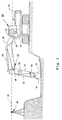
- an excavator 20 includes a plurality of tandem articulated members, generally shown in 22, which operate in unison in order to move a portion of one of the members, such as a cutting edge 24, along a plane that bears a relationship to a plane of light 26 generated by a laser beacon 28.
- Excavator 20 can excavate to either a horizontal plane or a plane on a slope even though plane of light and horizontal position 26 is horizontal.
- a laser sensor, or receiver 30 mounted to one of the members 22, passes through laser plane 26 occasionally as the operator controls movement of the excavator.
- a control system receives a user selection of a target depth and target slope and controls the movement of one or more of tandem articulated members 22 in order to maintain cutting edge 24 at a desired depth irrespective of movement of the manually controlled members.
- the operator controls a manual hydraulic valve (not shown), which regulates the flow of hydraulic fluid to a hydraulic cylinder 34, which controls the position of stick, or arm, 34 with respect to a boom 38.
- An encoder 40 monitors the relative angular position of arm 36 with respect to boom 38.
- the operator additionally has a manual control valve (not shown), which operates a cylinder 42, which pivots a bucket 44, with respect to arm 36.
- a bucket encoder 46 monitors the relative angular position of the bucket with respect to arm 36.
- the movement of a boom 38 is controlled by a hydraulic cylinder 48, which is under the control of the control system.
- a boom encoder 50 monitors relative angular position of the boom with respect to cab 52.
- Encoders 40, 46, and 50 may be rotary encoders operatively connected with the respective members, or may be linear encoders which respond to the extended length of the hydraulic cylinder (34, 42, 48) controlling the respective member, as disclosed in Nielsen et al. '418.
- encoders 40, 46, and 50 are commercially available optical rotary encoders, which are marketed by Hecon Corporation of Germany under Model No. RI41-0/3600 AR.11KB.
- the operator moves the joystick coupled with the manual control valves for cylinders 34 and 42 in order to reposition arm 36 and/or bucket 34.
- the typical movement is to drag the bucket in a plane in a direction toward the cab 52 in order to excavate with cutting edge 24.
- the control system responds to its various inputs, including the inputs from encoders 40, 46, and 50, in order to control the flow of hydraulic fluid to cylinder 48 and thereby control movement of boom 38.
- the control system moves the boom in a manner which maintains the vertical depth of cutting edge 24 at the target depth and on the target slope entered by the operator.
- arm 36 and bucket 44 are manually controlled members which are moved in response to the operator's joystick and boom 38 is an automatically controlled member whose movement is in response to manual movement of the arm and bucket. It is, of course, possible that boom 38 and bucket 44 be the manually controlled members with arm 36 being automatically controlled. However, such arrangement would be less intuitive to the operator and is, therefore, not preferred.
- Fig. 2 One difficulty with such an excavator control is illustrated by reference to Fig. 2.
- the signal represented by curve A illustrates the hydraulic pressure supplied to one of members 22, such as arm 36, in response to the operator's movement of the manual actuator, or joystick (not shown), for the arm. It is seen from curve A that movement of the lever causes a rapid increase in the hydraulic pressure supplied to the controlled cylinder (34,42,48).
- Curve B represents the movement of the associated member in response to the input command represented by curve A.
- a comparison of the signals indicates that there is a delay of a fraction of a second, such as, by way of example, 350 milliseconds, between the operator commanding movement of the member and the actual movement of the member.
- control signals provided to the cylinder (34, 42, 48) of the controlled member by the control system could lag behind those signals provided to the cylinder (34, 42, 48) of the manually operated member by a significant fraction of a second, or greater. Such delay could create an erratic movement of cutting edge 24.
- the inertia of the members, as well as such delays in the operation of the hydraulic control system could create instability in the movement of cutting edge 24 as the control system attempts to maintain cutting edge 24 at the desired depth.
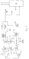
- Excavator 20 includes a control system 54 having a microprocessor or microcomputer 56 which receives inputs from encoders 40, 46 and 50 and provides an output 58 in order to control operation of boom 38 in a manner disclosed in the '809 patent.
- Microcomputer 56 additionally includes an input 60 which is supplied with a digital signal from an analog-to-digital (A/D) converter 62.
- A/D converter 62 may be built into microcomputer 56.
- A/D converter 62 is provided with an analog electrical signal on a line 64 which is the output of a pressure transducer 66.
- Pressure transducer 66 converts a pressure signal on a hydraulic line 68 to an electrical signal on line 64 which is proportional to the hydraulic signal at 68.
- Hydraulic line 68 is, in turn, supplied from an actuator, or joystick 70, which is supplied from a hydraulic pump 72.
- an actuator or joystick 70
- the movement of the joystick causes a variation in the hydraulic signal at hydraulic line 68 which is converted to an electrical signal by pressure transducer 66 and supplied as an input to microprocessor 56.
- Microprocessor 56 is additionally supplied with an input from an operator command input device 74.
- Input device 74 receives a user selection of an operator command code, which, in the illustrated embodiment, is selected in the range of from 1 to 10.
- Microprocessor 56 modulates the level of the hydraulic signal provided at 68 by the level of the operator command code provided with input 74 in order to provide an output 76 which ultimately controls the operation of hydraulic cylinder 34 in a manner which will be described in more detail below.
- Output 76 which is a digital signal, is converted to an analog signal by a digital-to-analog (D/A) converter 78 which may be a separate device or an integral part of microcomputer 56.
- An analog output 80 of D/A converter 78 is provided to a pilot valve 82 which responds thereto by overriding the operation of a main hydraulic control valve 84 in the same manner as disclosed in the '809 patent.
- Main hydraulic valve 84 is supplied from a hydraulic pump 86 and produces a hydraulic output 88 which operates hydraulic cylinder 34.
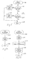
- Microcomputer 56 includes a control program 90, which, when initialized at 92, receives at 94 a pressured number at input 60 from the amount of actuation, if any, of joystick 70, an input command number from operator command input 74 and an arm velocity input from arm encoder 40. The program then determines at 96 whether the entered command number is equal to 8. If not, it determines at 98 whether the command number is equal to 9. If not, it determines at 100 whether the command number is equal to 10. If the command number is equal to 10, the control provides an output number at output 76 which is equal to the input number provided at input 60 (102). This mode provides a direct logic coupling between the operation of joystick 70 and the hydraulic control signal provided to hydraulic cylinder 34.
- control causes the hydraulic signal being provided to hydraulic cylinder 34 to be slightly responsive to the rate at which the operator operates joystick 70 (104). If it is determined at 98 that the command number is equal to 9, the control causes the hydraulic signal provided to hydraulic cylinder 34 to be heavily influenced by the rate at which the operator operates joystick 70 (106).
- the hydraulic signal provided to the arm hydraulic cylinder is more greatly under the control of the operator. If, in contrast, it is determined (96, 98, 100) that the command number is less than 8, the control treats the joystick like a switch at 108. In this manner, operation of hydraulic cylinder 34 is under the control of microprocessor 56 with the joystick merely providing a switch input to the microprocessor which determines only the direction of movement of the arm. The microcomputer ignores the rate and magnitude of movement of the joystick and merely responds to the direction of motion selected. Accordingly, the control ramps the arm 36 up to speed at a rate which is proportional to the command number entered by input 74 (110). Accordingly, for low values of command number, the rate increase in velocity of the arm is proportional to the command number, with the direction of the arm determined by the movement of joystick 70.
- An interrupt routine 112 is provided in order to prevent the operator from moving the arm at a rate of speed which cannot be compensated for by movement of the boom in order to avoid dips in excavating which would otherwise be outside of the plane of excavation or other such errors.
- Interrupt routine 112 is periodically initiated by a timer interrupt at 114 and a determination is made at 116 whether the arm 36 is moving too fast. This is accomplished by monitoring arm encoder 40. If it is determined at 116 that the arm is moving too fast, a decrease in pilot pressure supplied by pilot valve 82 is accomplished by manipulation of output 76 by microcomputer 56 (118). If it is determined at 116 that the arm is not moving too fast, it is then determined at 120 whether the arm is moving too slow.
- microcomputer 56 causes an increase in pilot pressure at 122. If it is determined at 120 that the arm is not moving too slow, then the return is exited at 124 in order to await the next timer interrupt. By controlling the pilot pressure, the control is able to regulate the speed of arm movement. An increase in pilot pressure increases the rate of arm movement and a decrease in pilot pressure decreases the rate of arm movement.
- a control program 130 includes provisions for measuring actual delay between movement of arm 36 and movement of boom 38 by monitoring encoders 40 and 50. After initialization at 132, program 130 determines at 134 whether the boom 38 and arm 36 are at rest. If it is determined at 134 that the boom and am, are at rest, an arm interrupt and a boom interrupt are enabled at 136. If it is determined at 134 that the boom and arm are not both at rest, then step 136 is bypassed and the interrupts are not enabled. Main control program 90 is then performed. After a pass through control program 90, it is then determined at 138 whether the interrupts are disabled.
- the parameter "delay-time” is modified as a function of the parameter "measured-time” at 140. If it is determined at 138 that the interrupts are not disabled, then no new measurement of actual delay time has been made and control returns to step 134.
- an arm interrupt 142 occurs in response to movement of the arm by monitoring arm encoder 40.
- a timer is initiated at 144 and the program is exited at 146.
- a boom interrupt 148 will occur upon initial movement of the boom as determined by monitoring boom encoder 50.
- the timer started at 144 will be stopped at 150 and the value of the time interval measured by the timer will be saved as the "measured-time" parameter at 152.
- the arm and boom interrupts are then disabled at 154 and the program exited at 156.
- the "measured-time” parameter represents the measured actual delay between the movement of the arm and movement of the boom. This parameter is utilized to adaptively modify the value of the "delay-time” parameter which is utilized by the program which controls operation of the boom in a manner disclosed in the '809 patent. Because the value of "delay-time" is a measured parameter rather than an assumed parameter, compensation for delay between operation of the arm and boom may be precisely preformed. This ensures precise compensation or overcompensation while avoiding under compensation. This prevents erroneous operation such as excavation of a dip below the plane, especially during initial excavation without detrimentally inhibiting the speed with which the operator can excavate. Thus, the present invention provides a system which is exceptionally responsive to the operator but precludes the operator from excavating in a manner which produces an unacceptable result.
Landscapes
- Engineering & Computer Science (AREA)
- Mining & Mineral Resources (AREA)
- Mechanical Engineering (AREA)
- Civil Engineering (AREA)
- General Engineering & Computer Science (AREA)
- Structural Engineering (AREA)
- Life Sciences & Earth Sciences (AREA)
- General Life Sciences & Earth Sciences (AREA)
- Paleontology (AREA)
- Operation Control Of Excavators (AREA)
Abstract
Description
Claims (30)
- A method of controlling a hydraulically operated construction machine having a plurality of tandem articulated members in a manner which moves said members in a particular pattern wherein movement of a first one of said members is controlled in response to movement of a second one of said members, including:determining anticipated future movement of said second member; andcontrolling said first member as a function at least of said anticipated future movement of said second member;
wherein said determining anticipated future movement includes measuring actual time delay between movement of said first and second members. - The method of claim 1 including providing encoders on said first and second members to monitor relative movement between said first member and a reference and between said second member and said first member and wherein said measuring actual time delay includes monitoring said encoders.
- The method of claim 2 wherein said measuring actual time delay includes determining a time difference between start of movement of one of said members and start of movement of the other of said members.
- The method of claim 3 including measuring actual time delay upon first start from rest operation of both said members and utilizing the measured time delay during successive start from rest operations of said members.
- The method of claim 1 wherein the construction machine includes an actuator operable by a user for controlling movement of said second member and wherein said determining future movement includes monitoring actuation of said actuator.
- The method of claim 1 including restricting the rate of movement of said second member below a predetermined rate.
- The method of claim 1 wherein said first member is a boom of an excavator and said second member is an arm of said excavator.
- A method of controlling a hydraulically operated construction machine having a plurality of tandem articulated members in a manner which moves said members in a particular pattern wherein movement of a first one of said members is controlled in response to movement of a second one of said members, including:providing an actuator operable by a user for controlling movement of one of said members;providing a motion-producing system which moves said one of said members in response to operation of said actuator;receiving a user input selection of a command level; andoperating said motion-producing system as a function of operation of said actuator and a value of said command level selected, wherein said second member is responsive to operation of said actuator in a manner which is determined at least in part by the selected value of said command level.
- The method of claim 8 wherein said motion-producing system includes a hydraulic cylinder and a hydraulic control valve for supplying hydraulic fluid to said hydraulic cylinder, wherein said operating said motion-producing system includes generating a signal in response to operation of said actuator and modifying said signal as a function of the selected value of said command level.
- The method of claim 9 wherein said operating said motion-producing system includes limiting the rate of movement of said at least one of said members as a function of the selected value of said command level.
- The method of claim 9 wherein said signal is a hydraulic signal and wherein said modifying said signal includes converting said hydraulic signal to an electrical input signal, supplying said input signal to a microcomputer, producing an electrical output signal of said microcomputer as a function at least of said input signal and said selected value of said command level, and converting said output signal to an output hydraulic signal and supplying said output hydraulic signal to said hydraulic control valve.
- The method of claim 8 including restricting the rate of movement of said one of said members below a predetermined rate.
- A hydraulically operated construction machine having a body, a plurality of tandem articulated members extending from said body, a hydraulic drive system for moving said members with respect to each other subject to a system delay, and a control for said hydraulic drive system which moves said members in a particular pattern, wherein movement of a first one of said members is controlled in response to movement of a second one of said members, comprising:position encoders on said first and second members, said position encoders monitoring the positions of said first and second members; anda control computer that is programmed to control movement of the first one of said members in response to movement of the second one of said members and to determine system delay by monitoring said position encoders to determine differences in first movements of said members.
- The hydraulically operated construction machine in claim 13 including an actuator operable by a user for controlling movement of said second one of said members.
- The hydraulically operated construction machine in claim 14 wherein said actuator operates a valve which produces a hydraulic signal proportional to amount of actuation of the actuator, the computer is programmed to adjust said hydraulic signal as a function of a command code entered by an operator and wherein said second one of said members is operated as a function of said adjusted hydraulic signal.
- The hydraulically operated construction machine in claim 15 including an input device for providing an input to said computer which is proportional to said hydraulic signal and an output device which is driven by said computer to produce said adjusted hydraulic signal.
- The hydraulically operated construction machine in claim 16 wherein said input device comprises a pressure transducer which produces an electronic signal as a function of said hydraulic signal and wherein said output device comprises a pilot valve which produces another hydraulic signal as a function of an output signal produced by said computer.
- The hydraulically operated construction machine in claim 15 wherein said computer increases said adjusted hydraulic signal at a rate that is a function of the value of said command code entered by an operator.
- The hydraulically operated construction machine in claim 14 wherein said computer is programmed to limit the speed at which said second one of said members is operated.
- The hydraulically operated construction machine in claim 13 wherein said first one of said members is an excavator boom pivotally connected with a base unit and wherein said second one of said members is an excavator arm pivotally connected with said boom.
- The hydraulically operated construction machine in claim 20 including a bucket pivotally connected with said arm and another actuator operable by a user for controlling movement of said bucket.
- A hydraulically operated construction machine having a body, a plurality of tandem articulated members extending from said body, a hydraulic drive system for moving said members with respect to each other subject to a system delay, and a control for said hydraulic drive system which moves said members in a particular pattern, wherein movement of a first one of said members is controlled in response to movement of a second one of said members, comprising:position encoders on said first and second members, said position encoders monitoring the positions of said first and second members; anda control computer that is programmed to control movement of the first one of said members in response to movement of the second one of said members;an actuator operable by a user for controlling movement of said second one of said members, wherein said actuator produces a hydraulic signal proportional to the amount of actuation of the actuator, the computer is programmed to adjust said signal as a function of a command code entered by an operator and wherein said second one of said members is operated as a function of said adjusted signal.
- The hydraulically operated construction machine in claim 22 including an input device for providing an input to said computer which is proportional to actuation of said actuator and an output device which is driven by said computer to produce said adjusted signal.
- The hydraulically operated construction machine in claim 23 wherein said signal is a hydraulic signal and said input device comprises a pressure transducer which produces an electronic signal as a function of said hydraulic signal and wherein said output device comprises a pilot valve which produces another hydraulic signal as a function of an output signal produced by said computer.
- The hydraulically operated construction machine in claim 23 wherein said signal is an electrical signal and said output device comprises a pilot valve which produces a hydraulic signal as a function of an output signal produced by said controller.
- The hydraulically operated construction machine in claim 22 wherein said computer increases said adjusted hydraulic signal at a rate that is a function of the value of said command code entered by an operator.
- The hydraulically operated construction machine in claim 22 wherein said computer is programmed to limit the speed at which said second one of said members is operated.
- The hydraulically operated construction machine in claim 22 wherein said first one of said members is an excavator boom pivotally connected with a base unit and wherein said second one of said members is an excavator arm pivotally connected with said boom.
- The hydraulically operated construction machine in claim 28 including a bucket pivotally connected with said arm and another actuator operable by a user for controlling movement of said bucket.
- A hydraulically operated construction machine having a body, a plurality of tandem articulated members extending from said body, a hydraulic drive system for moving said members with respect to each other up to a maximum speed capacity, and a control for said hydraulic drive system which moves said members in a particular pattern, wherein movement of a first one of said members is controlled in response to movement of a second one of said members, comprising:a control computer that is programmed to control movement of the first one of said members in response to movement of the second one of said members; andan actuator operable by a user for providing an input to said computer for controlling movement of said second one of said members;
wherein said computer limits the rate of movement of said second one of said members below the maximum speed capability of said second one of said members to move.
Applications Claiming Priority (2)
| Application Number | Priority Date | Filing Date | Title |
|---|---|---|---|
| US08/903,332 US5953838A (en) | 1997-07-30 | 1997-07-30 | Control for hydraulically operated construction machine having multiple tandem articulated members |
| US903332 | 2001-07-11 |
Publications (2)
| Publication Number | Publication Date |
|---|---|
| EP0894901A2 true EP0894901A2 (en) | 1999-02-03 |
| EP0894901A3 EP0894901A3 (en) | 1999-11-10 |
Family
ID=25417321
Family Applications (1)
| Application Number | Title | Priority Date | Filing Date |
|---|---|---|---|
| EP98114208A Withdrawn EP0894901A3 (en) | 1997-07-30 | 1998-07-29 | Control for hydraulically operated construction machine having multiple tandem articulated members |
Country Status (3)
| Country | Link |
|---|---|
| US (1) | US5953838A (en) |
| EP (1) | EP0894901A3 (en) |
| JP (1) | JPH11107326A (en) |
Cited By (4)
| Publication number | Priority date | Publication date | Assignee | Title |
|---|---|---|---|---|
| WO2003052532A1 (en) * | 2001-12-14 | 2003-06-26 | Caterpillar Inc. | Operator input/output interface control determines existance of potential conditions for receiving undesired command signals |
| DE202005020462U1 (en) * | 2005-12-08 | 2007-04-19 | Liebherr-Werk Ehingen Gmbh | crane |
| EP2275604A1 (en) * | 2009-06-17 | 2011-01-19 | BAUER Maschinen GmbH | machine with scaffold |
| CN107806123A (en) * | 2016-09-08 | 2018-03-16 | 哈尼斯菲格技术公司 | The system and method for industrial machine semiautomatic control |
Families Citing this family (25)
| Publication number | Priority date | Publication date | Assignee | Title |
|---|---|---|---|---|
| SE9704398L (en) * | 1997-11-28 | 1998-12-14 | Spectra Precision Ab | Device and method for determining the position of the machining part |
| JP3790058B2 (en) * | 1999-01-14 | 2006-06-28 | 株式会社神戸製鋼所 | Excavator control device |
| US6484083B1 (en) * | 1999-06-07 | 2002-11-19 | Sandia Corporation | Tandem robot control system and method for controlling mobile robots in tandem |
| AU2002331786A1 (en) * | 2001-08-31 | 2003-03-18 | The Board Of Regents Of The University And Community College System, On Behalf Of The University Of | Coordinated joint motion control system |
| US6604305B2 (en) | 2001-09-28 | 2003-08-12 | Caterpillar Inc | Method and apparatus for controlling an extendable stick on a work machine |
| US7040044B2 (en) * | 2003-12-15 | 2006-05-09 | Caterpillar S.A.R.L. | Method of modulating a boom assembly to perform in a linear manner |
| US7168174B2 (en) * | 2005-03-14 | 2007-01-30 | Trimble Navigation Limited | Method and apparatus for machine element control |
| US8065060B2 (en) | 2006-01-18 | 2011-11-22 | The Board Of Regents Of The University And Community College System On Behalf Of The University Of Nevada | Coordinated joint motion control system with position error correction |
| US7734398B2 (en) * | 2006-07-31 | 2010-06-08 | Caterpillar Inc. | System for automated excavation contour control |
| US8363210B2 (en) * | 2007-10-26 | 2013-01-29 | Deere & Company | Three dimensional feature location from an excavator |
| US8817238B2 (en) | 2007-10-26 | 2014-08-26 | Deere & Company | Three dimensional feature location from an excavator |
| US8024095B2 (en) | 2008-03-07 | 2011-09-20 | Caterpillar Inc. | Adaptive work cycle control system |
| US8156048B2 (en) * | 2008-03-07 | 2012-04-10 | Caterpillar Inc. | Adaptive payload monitoring system |
| US8185290B2 (en) * | 2008-03-07 | 2012-05-22 | Caterpillar Inc. | Data acquisition system indexed by cycle segmentation |
| US8285458B2 (en) * | 2008-04-18 | 2012-10-09 | Caterpillar Inc. | Machine with automatic operating mode determination |
| US8190336B2 (en) * | 2008-07-17 | 2012-05-29 | Caterpillar Inc. | Machine with customized implement control |
| US8362629B2 (en) * | 2010-03-23 | 2013-01-29 | Bucyrus International Inc. | Energy management system for heavy equipment |
| JP5852667B2 (en) * | 2011-10-17 | 2016-02-03 | 日立建機株式会社 | Dump truck stop position direction indication system and transport system |
| US20130167410A1 (en) * | 2011-12-31 | 2013-07-04 | Brian Bernard Langdon | Clam-link apparatus and methods |
| WO2014061790A1 (en) * | 2012-10-19 | 2014-04-24 | 株式会社小松製作所 | Excavation control system for hydraulic shovel |
| WO2015030265A1 (en) * | 2014-09-05 | 2015-03-05 | 株式会社小松製作所 | Hydraulic shovel |
| US10870968B2 (en) * | 2018-04-30 | 2020-12-22 | Deere & Company | Work vehicle control system providing coordinated control of actuators |
| WO2022064823A1 (en) * | 2020-09-28 | 2022-03-31 | 日本電気株式会社 | Work control method, work control system, work control device, and non-transitory computer-readable medium with work control program recorded |
| US12590440B2 (en) * | 2021-06-28 | 2026-03-31 | Doosan Bobcat North America, Inc. | Systems and methods for control of excavators and other power machines |
| JP2024055024A (en) * | 2022-10-06 | 2024-04-18 | 日立建機株式会社 | Work Machine |
Family Cites Families (59)
| Publication number | Priority date | Publication date | Assignee | Title |
|---|---|---|---|---|
| DE1445933A1 (en) * | 1962-02-21 | 1969-02-13 | Ici Ltd | Process for the production of organic bases |
| DE1788001A1 (en) * | 1967-09-14 | 1972-01-05 | Unicovske Strojicny N P | Switching arrangement for the analog-programmed control of machines equipped with a boom for earthworks |
| US3708232A (en) * | 1970-09-16 | 1973-01-02 | R Walsh | Read-out means for locating and positioning objects with respect to a laser beam reference |
| US3727332A (en) * | 1971-11-22 | 1973-04-17 | W Zimmer | Laser guidance system for grade control |
| US3813171A (en) * | 1973-01-11 | 1974-05-28 | Laserplane Corp | Laser beam survey method and apparatus |
| US3887012A (en) * | 1973-12-03 | 1975-06-03 | Caterpillar Tractor Co | Automatic levelling system for earth working blades and the like |
| US4162708A (en) * | 1975-02-03 | 1979-07-31 | Dakota Electron, Inc. | Tool carrying vehicle with laser control apparatus |
| US3997071A (en) * | 1975-08-14 | 1976-12-14 | Laserplane Corporation | Method and apparatus for indicating effective digging depth of a backhoe |
| US4034490A (en) * | 1975-11-03 | 1977-07-12 | Laserplane Corporation | Automatic depth control for endless chain type trencher |
| US4050171A (en) * | 1976-05-12 | 1977-09-27 | Laserplane Corporation | Depth control for endless chain type trencher |
| US4286386A (en) * | 1977-09-06 | 1981-09-01 | Long Irvin E | Electro-mechanical displacement measuring device |
| US4129224A (en) * | 1977-09-15 | 1978-12-12 | Laserplane Corporation | Automatic control of backhoe digging depth |
| JPS54150802A (en) * | 1978-05-16 | 1979-11-27 | Komatsu Mfg Co Ltd | Blade automatic controller of bulldozer and its method |
| US4231700A (en) * | 1979-04-09 | 1980-11-04 | Spectra-Physics, Inc. | Method and apparatus for laser beam control of backhoe digging depth |
| US4288196A (en) * | 1979-06-14 | 1981-09-08 | Sutton Ii James O | Computer controlled backhoe |
| JPS5697023A (en) * | 1980-01-07 | 1981-08-05 | Komatsu Ltd | Semiautomatic oil pressure excavator |
| US4491927A (en) * | 1980-04-11 | 1985-01-01 | The Digger Meter Corporation | Depth monitoring system |
| SE436436B (en) * | 1981-06-18 | 1984-12-10 | Eurotrade Machine Pool Ab | DEPTH METER FOR EXCAVATORS |
| US4413684A (en) * | 1981-07-27 | 1983-11-08 | Duncklee Timothy V | Laser-controlled ground leveling device with overfill sensor and wheel rise limiting device |
| DE3268084D1 (en) * | 1982-03-31 | 1986-02-06 | Scheuchzer Fils Auguste | Control device for a railway track construction or maintenance machine |
| US4514796A (en) * | 1982-09-08 | 1985-04-30 | Joy Manufacturing Company | Method and apparatus for controlling the position of a hydraulic boom |
| JPS59195936A (en) * | 1983-04-21 | 1984-11-07 | Komatsu Ltd | How to monitor the working status of excavating machines |
| US4600997A (en) * | 1983-05-09 | 1986-07-15 | Spectra-Physics, Inc. | Surveying system |
| JPS6033940A (en) * | 1983-08-02 | 1985-02-21 | Hitachi Constr Mach Co Ltd | Controller for straight excavation by oil-pressure shovel |
| US4758970A (en) * | 1984-08-08 | 1988-07-19 | Emco Wheaton, Inc. | Marine loading arm monitoring system |
| DE3506326C1 (en) * | 1985-02-22 | 1986-08-21 | Harms, Paul G., 6253 Hadamar | Depth measuring device for an excavator |
| DE3506304C1 (en) * | 1985-02-22 | 1986-04-10 | Harms, Paul G., 6253 Hadamar | Optoelectronic measuring receiver and method for controlling the optoelectronic measuring receiver |
| US4722044A (en) * | 1985-03-19 | 1988-01-26 | Sundstrand Corporation | Boom control system |
| JPS61248104A (en) * | 1985-04-26 | 1986-11-05 | Nissan Motor Co Ltd | Manipulator controlling device |
| JPH0631527B2 (en) * | 1985-04-30 | 1994-04-27 | マツダ株式会社 | Boom positioning device for drilling machine |
| JPS6145025A (en) * | 1985-07-10 | 1986-03-04 | Hitachi Ltd | How to install a sump pit |
| US4866641A (en) * | 1987-04-24 | 1989-09-12 | Laser Alignment, Inc. | Apparatus and method for controlling a hydraulic excavator |
| US4829418A (en) * | 1987-04-24 | 1989-05-09 | Laser Alignment, Inc. | Apparatus and method for controlling a hydraulic excavator |
| US4805086A (en) * | 1987-04-24 | 1989-02-14 | Laser Alignment, Inc. | Apparatus and method for controlling a hydraulic excavator |
| US4910673A (en) * | 1987-05-29 | 1990-03-20 | Hitachi Construction Machinery Co., Ltd. | Apparatus for controlling arm movement of industrial vehicle |
| US4884939A (en) * | 1987-12-28 | 1989-12-05 | Laser Alignment, Inc. | Self-contained laser-activated depth sensor for excavator |
| US4947336A (en) * | 1988-04-15 | 1990-08-07 | Froyd Stanley G | Multiple axis motion control system |
| JP2670815B2 (en) * | 1988-07-29 | 1997-10-29 | 株式会社小松製作所 | Control equipment for construction machinery |
| US5116186A (en) * | 1988-08-02 | 1992-05-26 | Kabushiki Kaisha Komatsu Seisakusho | Apparatus for controlling hydraulic cylinders of a power shovel |
| US4888890A (en) * | 1988-11-14 | 1989-12-26 | Spectra-Physics, Inc. | Laser control of excavating machine digging depth |
| GB2225127B (en) * | 1988-11-18 | 1993-03-31 | Kubota Ltd | Pivotal movement control device for boom-equipped working machine |
| JPH02232430A (en) * | 1989-03-03 | 1990-09-14 | Komatsu Ltd | Controller for depth of excavation of hydraulic shovel |
| JP2687169B2 (en) * | 1989-06-20 | 1997-12-08 | 株式会社小松製作所 | Slope work control device for construction machinery |
| US5065326A (en) * | 1989-08-17 | 1991-11-12 | Caterpillar, Inc. | Automatic excavation control system and method |
| JP2631757B2 (en) * | 1990-05-22 | 1997-07-16 | 油谷重工株式会社 | Excavation control method for construction machinery |
| JP2682891B2 (en) * | 1990-07-25 | 1997-11-26 | 新キャタピラー三菱株式会社 | Excavator control equipment for power shovel |
| DE4030954C2 (en) * | 1990-09-29 | 1994-08-04 | Danfoss As | Method for controlling the movement of a hydraulically movable implement and path control device for carrying out the method |
| JP2736569B2 (en) * | 1991-01-23 | 1998-04-02 | 新キャタピラー三菱株式会社 | Operating method of hydraulic excavator |
| KR950001445A (en) * | 1993-06-30 | 1995-01-03 | 경주현 | How to maintain swing speed of excavator and speed ratio of boom |
| KR950001446A (en) * | 1993-06-30 | 1995-01-03 | 경주현 | How to control automatic repetitive work of excavator |
| GB9323298D0 (en) * | 1993-11-11 | 1994-01-05 | Mastenbroek & Co Ltd J | Improvements in and relating to excavating apparatus |
| EP0731221A4 (en) * | 1993-11-30 | 1997-12-29 | Komatsu Mfg Co Ltd | Linear excavating control device for a hydraulic power shovel |
| US5446980A (en) * | 1994-03-23 | 1995-09-05 | Caterpillar Inc. | Automatic excavation control system and method |
| US5438771A (en) * | 1994-05-10 | 1995-08-08 | Caterpillar Inc. | Method and apparatus for determining the location and orientation of a work machine |
| US5572809A (en) * | 1995-03-30 | 1996-11-12 | Laser Alignment, Inc. | Control for hydraulically operated construction machine having multiple tandem articulated members |
| JP3112814B2 (en) * | 1995-08-11 | 2000-11-27 | 日立建機株式会社 | Excavation control device for construction machinery |
| KR0168992B1 (en) * | 1995-10-31 | 1999-02-18 | 유상부 | Control method for an excavator |
| US5682311A (en) * | 1995-11-17 | 1997-10-28 | Clark; George J. | Apparatus and method for controlling a hydraulic excavator |
| US5854988A (en) * | 1996-06-05 | 1998-12-29 | Topcon Laser Systems, Inc. | Method for controlling an excavator |
-
1997
- 1997-07-30 US US08/903,332 patent/US5953838A/en not_active Expired - Fee Related
-
1998
- 1998-07-29 EP EP98114208A patent/EP0894901A3/en not_active Withdrawn
- 1998-07-29 JP JP10227545A patent/JPH11107326A/en active Pending
Cited By (7)
| Publication number | Priority date | Publication date | Assignee | Title |
|---|---|---|---|---|
| WO2003052532A1 (en) * | 2001-12-14 | 2003-06-26 | Caterpillar Inc. | Operator input/output interface control determines existance of potential conditions for receiving undesired command signals |
| DE202005020462U1 (en) * | 2005-12-08 | 2007-04-19 | Liebherr-Werk Ehingen Gmbh | crane |
| US7665620B2 (en) | 2005-12-08 | 2010-02-23 | Liebherr-Werk Ehingen Gmbh | Crane |
| EP2275604A1 (en) * | 2009-06-17 | 2011-01-19 | BAUER Maschinen GmbH | machine with scaffold |
| US8483915B2 (en) | 2009-06-17 | 2013-07-09 | Bauer Maschinen Gmbh | Construction apparatus for foundation construction |
| CN107806123A (en) * | 2016-09-08 | 2018-03-16 | 哈尼斯菲格技术公司 | The system and method for industrial machine semiautomatic control |
| CN107806123B (en) * | 2016-09-08 | 2022-04-15 | 久益环球地表采矿公司 | System and method for semi-automatic control of industrial machines |
Also Published As
| Publication number | Publication date |
|---|---|
| US5953838A (en) | 1999-09-21 |
| EP0894901A3 (en) | 1999-11-10 |
| JPH11107326A (en) | 1999-04-20 |
Similar Documents
| Publication | Publication Date | Title |
|---|---|---|
| US5953838A (en) | Control for hydraulically operated construction machine having multiple tandem articulated members | |
| US5572809A (en) | Control for hydraulically operated construction machine having multiple tandem articulated members | |
| CA2020234C (en) | Automatic excavation control system and method | |
| EP0791694B1 (en) | Apparatus and method for controlling a construction machine | |
| US7934329B2 (en) | Semi-autonomous excavation control system | |
| KR100227197B1 (en) | Interference prevention device of construction machine | |
| US5490081A (en) | Working tool operation range limiting apparatus | |
| US6498973B2 (en) | Flow control for electro-hydraulic systems | |
| US6108948A (en) | Method and device for controlling construction machine | |
| US5116186A (en) | Apparatus for controlling hydraulic cylinders of a power shovel | |
| US6140787A (en) | Method and apparatus for controlling a work implement | |
| US5178510A (en) | Apparatus for controlling the hydraulic cylinder of a power shovel | |
| US5975214A (en) | Working machine control device for construction machinery | |
| JPWO1998030759A1 (en) | Interference prevention device for two-piece boom hydraulic excavators | |
| JPH0868069A (en) | Control system automatically controlling operating tool for soil moving machine for obtaining material | |
| JPH0794737B2 (en) | Linear excavation control device in hydraulic excavator | |
| US6618967B2 (en) | Work machine control for improving cycle time | |
| JPH09228404A (en) | Work machine control method of construction machine and device thereof | |
| US20250257549A1 (en) | Automatic driving system for work machine | |
| JP3713358B2 (en) | Front control device for construction machinery | |
| JPH0788674B2 (en) | Power shovel work machine controller | |
| EP4545801A1 (en) | Hydraulic drive device | |
| JP3217981B2 (en) | Control equipment for construction machinery | |
| JP3727423B2 (en) | Control method of electronically controlled work vehicle | |
| JPH111937A (en) | Front attachment angle control apparatus for construction machine |
Legal Events
| Date | Code | Title | Description |
|---|---|---|---|
| PUAI | Public reference made under article 153(3) epc to a published international application that has entered the european phase |
Free format text: ORIGINAL CODE: 0009012 |
|
| AK | Designated contracting states |
Kind code of ref document: A2 Designated state(s): DE DK FR GB IT NL SE |
|
| AX | Request for extension of the european patent |
Free format text: AL;LT;LV;MK;RO;SI |
|
| PUAL | Search report despatched |
Free format text: ORIGINAL CODE: 0009013 |
|
| AK | Designated contracting states |
Kind code of ref document: A3 Designated state(s): AT BE CH CY DE DK ES FI FR GB GR IE IT LI LU MC NL PT SE |
|
| AX | Request for extension of the european patent |
Free format text: AL;LT;LV;MK;RO;SI |
|
| 17P | Request for examination filed |
Effective date: 20000508 |
|
| AKX | Designation fees paid |
Free format text: DE DK FR GB IT NL SE |
|
| RBV | Designated contracting states (corrected) |
Designated state(s): DE DK FR GB IT NL SE |
|
| 17Q | First examination report despatched |
Effective date: 20020607 |
|
| STAA | Information on the status of an ep patent application or granted ep patent |
Free format text: STATUS: THE APPLICATION IS DEEMED TO BE WITHDRAWN |
|
| 18D | Application deemed to be withdrawn |
Effective date: 20021217 |