EP0894257B1 - Chemical sampling/dispensing apparatus - Google Patents
Chemical sampling/dispensing apparatus Download PDFInfo
- Publication number
- EP0894257B1 EP0894257B1 EP97916523A EP97916523A EP0894257B1 EP 0894257 B1 EP0894257 B1 EP 0894257B1 EP 97916523 A EP97916523 A EP 97916523A EP 97916523 A EP97916523 A EP 97916523A EP 0894257 B1 EP0894257 B1 EP 0894257B1
- Authority
- EP
- European Patent Office
- Prior art keywords
- sleeve
- gas
- vessel
- chemical sampling
- dispensing means
- Prior art date
- Legal status (The legal status is an assumption and is not a legal conclusion. Google has not performed a legal analysis and makes no representation as to the accuracy of the status listed.)
- Expired - Lifetime
Links
Images
Classifications
-
- B—PERFORMING OPERATIONS; TRANSPORTING
- B01—PHYSICAL OR CHEMICAL PROCESSES OR APPARATUS IN GENERAL
- B01L—CHEMICAL OR PHYSICAL LABORATORY APPARATUS FOR GENERAL USE
- B01L3/00—Containers or dishes for laboratory use, e.g. laboratory glassware; Droppers
- B01L3/02—Burettes; Pipettes
-
- G—PHYSICS
- G01—MEASURING; TESTING
- G01N—INVESTIGATING OR ANALYSING MATERIALS BY DETERMINING THEIR CHEMICAL OR PHYSICAL PROPERTIES
- G01N1/00—Sampling; Preparing specimens for investigation
- G01N1/02—Devices for withdrawing samples
-
- G—PHYSICS
- G01—MEASURING; TESTING
- G01N—INVESTIGATING OR ANALYSING MATERIALS BY DETERMINING THEIR CHEMICAL OR PHYSICAL PROPERTIES
- G01N35/00—Automatic analysis not limited to methods or materials provided for in any single one of groups G01N1/00 - G01N33/00; Handling materials therefor
- G01N35/10—Devices for transferring samples or any liquids to, in, or from, the analysis apparatus, e.g. suction devices, injection devices
- G01N35/1004—Cleaning sample transfer devices
-
- B—PERFORMING OPERATIONS; TRANSPORTING
- B01—PHYSICAL OR CHEMICAL PROCESSES OR APPARATUS IN GENERAL
- B01L—CHEMICAL OR PHYSICAL LABORATORY APPARATUS FOR GENERAL USE
- B01L2200/00—Solutions for specific problems relating to chemical or physical laboratory apparatus
- B01L2200/06—Fluid handling related problems
- B01L2200/0647—Handling flowable solids, e.g. microscopic beads, cells, particles
- B01L2200/0657—Pipetting powder
-
- B—PERFORMING OPERATIONS; TRANSPORTING
- B01—PHYSICAL OR CHEMICAL PROCESSES OR APPARATUS IN GENERAL
- B01L—CHEMICAL OR PHYSICAL LABORATORY APPARATUS FOR GENERAL USE
- B01L2200/00—Solutions for specific problems relating to chemical or physical laboratory apparatus
- B01L2200/08—Ergonomic or safety aspects of handling devices
- B01L2200/082—Handling hazardous material
-
- B—PERFORMING OPERATIONS; TRANSPORTING
- B01—PHYSICAL OR CHEMICAL PROCESSES OR APPARATUS IN GENERAL
- B01L—CHEMICAL OR PHYSICAL LABORATORY APPARATUS FOR GENERAL USE
- B01L2200/00—Solutions for specific problems relating to chemical or physical laboratory apparatus
- B01L2200/14—Process control and prevention of errors
- B01L2200/141—Preventing contamination, tampering
-
- B—PERFORMING OPERATIONS; TRANSPORTING
- B01—PHYSICAL OR CHEMICAL PROCESSES OR APPARATUS IN GENERAL
- B01L—CHEMICAL OR PHYSICAL LABORATORY APPARATUS FOR GENERAL USE
- B01L2300/00—Additional constructional details
- B01L2300/10—Means to control humidity and/or other gases
-
- B—PERFORMING OPERATIONS; TRANSPORTING
- B01—PHYSICAL OR CHEMICAL PROCESSES OR APPARATUS IN GENERAL
- B01L—CHEMICAL OR PHYSICAL LABORATORY APPARATUS FOR GENERAL USE
- B01L2400/00—Moving or stopping fluids
- B01L2400/04—Moving fluids with specific forces or mechanical means
- B01L2400/0475—Moving fluids with specific forces or mechanical means specific mechanical means and fluid pressure
- B01L2400/0478—Moving fluids with specific forces or mechanical means specific mechanical means and fluid pressure pistons
-
- B—PERFORMING OPERATIONS; TRANSPORTING
- B01—PHYSICAL OR CHEMICAL PROCESSES OR APPARATUS IN GENERAL
- B01L—CHEMICAL OR PHYSICAL LABORATORY APPARATUS FOR GENERAL USE
- B01L2400/00—Moving or stopping fluids
- B01L2400/04—Moving fluids with specific forces or mechanical means
- B01L2400/0475—Moving fluids with specific forces or mechanical means specific mechanical means and fluid pressure
- B01L2400/0487—Moving fluids with specific forces or mechanical means specific mechanical means and fluid pressure fluid pressure, pneumatics
Definitions
- This invention relates to chemical sampling and dispensing.
- Such devices have problems, however, in that they are unable to accurately sample and dispense viscous liquids, that the act of drawing or dispensing the substance may, if the substance is volatile, cause the substance to vaporise, they block easily, condensation and ice can form easily on their outer surface when handling cold liquids, and in that they cannot handle solids or suspension of solids in slurry form.
- the present invention is directed toward providing a chemical sampling or dispensing apparatus which isolates the chemical from air and moisture, yet which is able to deal with solids, viscous and volatile liquids.
- DE-A-4432599 discloses a gas shroud with fixed gas dispenser, which can be placed over a vessel.
- EP-A-517606, US-A-4804372, and US-A-4110590 disclose systems employing gas supplies.
- a chemical sampling or dispensing apparatus comprising:
- the chemical sampling or dispensing means may be a pipette, fluid line from a pump, syringe or displacement plunger device, and may be arranged to slide axially within the sleeve.
- the sleeve may be formed from two shrouds, one arranged to slide within the other, the sliding engagement of the two shrouds being controlled by engagement of the first end of the sleeve with the vessel inlet and either the pressure of input inert gas or a biasing member.
- the sleeve may be of unit construction and be arranged such that the area to be shrouded is brought inside the shroud to make connection with the sampling device.
- the first end of the sleeve may be open and may incorporate a gas seal or venturi flow arrangement to ensure that no air or moisture enters the sleeve. Alternatively, it may be covered by a hinged sealing door
- the apparatus may be arranged to be hand held or may be arranged to be operated by a robot.
- a sleeve filled with a flow of inert gas ensures that no air or moisture is able to enter the region surrounding the sampling or dispensing means and contaminate the sample and eliminates the formation of condensation or ice.
- a further advantage of the invention is that it is not restricted to use with needles and self sealing septa.
- An advantage of the invention is that the shroud gas need only be switched on when a transfer is being made, thus saving expensive gas. It can allow larger objects to access vessels through the openings.
- the shroud can accommodate a decapper and can provide a gas shield while the vessel is decapped, accessed by a large probe, and then recapped.
- the shroud may incorporate a means of opening or de-capping a vessel.
- the shroud itself may open a cap, or ports in a cap, by push, pull or rotary action.
- the insert gas supply may be arranged to flow through the inside of the shroud such that it may cool electronic, electrical, optical and mechanical components and/or protect them from corrosive fumes.
- these components could include for example circuits, motors, solenoids, sensors and analytical equipment.
- the shroud may contain a non-contact infra-red thermocouple which can be used to measure the temperature of the contents of a vessel by imaging the contents through an opened port. Sensors attached to the shroud may be used for feed-back control of the shroud functions, including sensing of the cap position, volume of the vessel and monitoring and control of the gas flow to maintain the gas blanket.
- the vessel may be a reaction vessel or storage container.
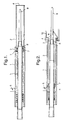
- a chemical sampling or dispensing apparatus has a sleeve 1 which comprises an inner shroud 2 and outer shroud 3.
- the two shrouds 2, 3 are arranged so that the inner shroud 2 slides telescopically within the outer shroud 1.
- the inner shroud 2 has an open end 4 which is arranged to engage with an inlet to the vessel 10 (Fig. 2) .
- a biasing spring 5 biases the inner shroud 2 outward from the outer shroud 3.
- a gas inlet 6 is provided on the outer shroud 3 so that inert gas, such as Argon or Nitrogen, can be pumped into the outer shroud 3 and on to the inside of inner shroud 2 via passageways 7. The inert gas can then pass out of the open end 4 of the inner shroud 2, creating a flow of inert gas through the sleeve.
- a chemical sampling or dispensing device 8 is positioned within the sleeve 1 and arranged so that its sampling or dispensing end 9 is adjacent to the open end 4 of the inner shroud 2.
- a plunger displacement device which is capable of both dispensing and sampling chemicals is shown, although it will be appreciated that this device could be replaced with equivalent devices, such as a syringe and needle, liquid supply pipe or pipette arrangement.
- the inner shroud 2 slides within the outer shroud 3, and allows the sampling or dispensing end 9 of the sampling or dispensing apparatus 8 to enter the inlet to the vessel 10. Because of the flow of inert gas, even if the open end 4 of the inner shroud 2 does not provide a tight seal with the inlet to the vessel 10, no air or moisture is able to enter the sleeve 1 and come into contact with the sampling or dispensing apparatus 8.
- the apparatus can be moved away from the inlet to the vessel 10 and, because of the spring biasing of the inner shroud 2, the sampling or dispensing end 9 of the sampling or dispensing apparatus 8 never comes into contact with the air. Even when the apparatus is fully removed, because inert gas is flowing around the dispensing or sampling end 9, a blanket of inert gas is provided which prevents air contact.
- An electrochemical oxygen probe was calibrated to read oxygen concentrations in the range 0-100% of the normal atmospheric oxygen partial pressure.
- the 0% calibration point was obtained with a sodium sulphite zero oxygen standard solution.
- the 100% calibration point was measured in free atmospheric air.
- the oxygen sensor was placed in the mouth of the shroud, at a position corresponding to the end of the pipette tip 9. Dry zero-grade nitrogen gas was introduced into the shroud through inlet 6 and the gas flow was gradually increased until the meter read 0% oxygen. This corresponded with a flow rate of approximately 0.35 standard litres per minute (SLPM).
- the flow rate was fixed at 0.4 SLPM and the device was tested for air exclusion using a colour-change oxygen sensitive reagent (sodium dithionite, 10% KOH and indigo carmine, which turns from yellow to blue in the presence of oxygen).
- the air sensitive reagent was taken up into the pipette tip 9 from a gas-blanketed vessel. The device was then left standing in free air. No colour change was observed after one hour, indicating that little or no oxygen had contaminated the tip contents. By contrast, the reagent changed colour almost immediately in the absence of blanket gas.
- a series of tests were carried out where an oxygen sensitive reagent was repeatedly transferred between vessels. Again, no ingress of oxygen was observed.
- the stream of gas coming out of the end of the shroud can provide some protection from air contamination some distance beyond the end of the shroud tube.
- reaction vessel may have a sealing lid or membrane 12, in which case, the open end 4 of the inner shroud 2, or (as shown) the sampling/dispensing device 8, may be arranged to break the seal on contact with the vessel 10.
- the spring 5 could be replaced by increased inert gas pressure, which could provide an equivalent biasing force.
- the extension and retraction of the shroud tube may be motorised such that the shroud may be set to any position at will. This is useful where, for example, the target vessel could be knocked over or moved if the shroud was to come in contact with it. It is also desirable to retract the shroud to allow cleaning, inspection or replacement of the sampling device.
- the shroud retraction mechanism can form part of a tool or pipette pick-up mechanism, and may incorporate a limit sensor to prevent damage in the event of encountering an obstruction.
- the apparatus may be adapted to be moved and controlled by a robot, or may, alternatively, be a handheld device.
- a further advantage of the present invention lies in the possibility for the gas inlet 6 to provide gas to the vessel 10 once the sleeve 1 has engaged with it. This allows for the application of gas to the vessel 10 to assist the reaction by agitating vessel contents or in order to add an inert gas blanket to the vessel 10. Furthermore, gas may be supplied via the gas inlet 6 to displace liquid from the vessel 10.
- the invention can also be used for transferring samples in microbiology or radiochemistry.
- the shroud can be supplied with a flow of sterile gas (or air).
- the gas blanket will maintain the sterility of any sampling device contained within the shroud. This is useful for taking and transferring samples where contamination needs to be avoided.
- the invention can be configured to shroud several openings simultaneously, independently or collectively.
- a system with multiple shroud would allow independent shrouding of multiple openings. This would prevent vapour from one opening contaminating an adjacent opening.
- a single shroud may be used to blanket multiple openings, such as a 96-well plate used in high throughput screening.
- the invention may also be configured with concentric inner and outer shrouds.
- a concentric shroud arrangement with an inner shroud supplying gas and an outer shroud connected to a fume extraction system can be used to shroud an open port, while simultaneously taking away noxious or hazardous fumes.
- This embodiment of the invention can be used for the handling and containment of hazardous substances, such as chemical, biological and radiochemical samples, where vapours could be hazardous to the operator.
- the shroud may be manufactured of glass, ceramic, plastic or metal or other suitable material.
- the shroud could be made of lead or another radiation shielding material to protect an operator when the system is used with radioactive chemicals. Where the shroud is being used in the transfer of aggressive substances, only the end of the shroud needs to be made from an inert material because the shroud gas protects the uppermost internal parts of the shroud.
Landscapes
- Chemical & Material Sciences (AREA)
- Health & Medical Sciences (AREA)
- General Health & Medical Sciences (AREA)
- General Physics & Mathematics (AREA)
- Physics & Mathematics (AREA)
- Life Sciences & Earth Sciences (AREA)
- Analytical Chemistry (AREA)
- Biochemistry (AREA)
- Pathology (AREA)
- Immunology (AREA)
- Chemical Kinetics & Catalysis (AREA)
- Clinical Laboratory Science (AREA)
- Sampling And Sample Adjustment (AREA)
- Nitrogen Condensed Heterocyclic Rings (AREA)
- Automatic Analysis And Handling Materials Therefor (AREA)
- Devices For Use In Laboratory Experiments (AREA)
- Feeding, Discharge, Calcimining, Fusing, And Gas-Generation Devices (AREA)
Abstract
Description
Claims (20)
- A chemical sampling or dispensing apparatus comprising:a sleeve (1) having a first end (4) arranged to engage with an inlet to a vessel, and a gas inlet (6) for receiving, in use, an inert gas and directing it toward the first end of the sleeve, wherein the sleeve is arranged to at least partially surround a chemical sampling or dispensing means; anda chemical sampling or dispensing means (8) arranged to dispense or take samples from the vessel inlet through the first end of the sleeve, characterised in that the chemical sampling or dispensing means is arranged to slide axially within the sleeve.
- An apparatus according to claim 1, wherein the chemical sampling or dispensing means (8) is a pipette.
- An apparatus according to claim 1, wherein the chemical sampling or dispensing means (8) is a fluid line from a pump.
- An apparatus according to claim 1, wherein the chemical sampling or dispensing means (8) is a syringe.
- An apparatus according to claim 1, wherein the chemical sampling or dispensing means (8) is a displacement plunger device.
- An apparatus according to claim 1, wherein the chemical sampling or dispensing means (8) is a solids handling device.
- An apparatus according to claim 1, wherein the chemical sampling or dispensing means (8) is a gas pipe.
- An apparatus according to any of the preceding claims, wherein the sleeve (1) is formed from two shrouds (2,3), one arranged to slide within the other, the sliding engagement of the two shrouds being controlled by engagement of the first end (4) of the sleeve (1) with the vessel inlet and either the pressure of input inert gas or a biasing member.
- An apparatus according to any of claims 1 to 7, wherein the sleeve (1) is unitary in construction and is arranged such that the area to be shrouded is brought inside the sleeve to make connection with the sampling device (8).
- An apparatus according to any of the preceding claims, wherein the first end of the sleeve (1) is open.
- An apparatus according to any of claims 1 to 9, wherein the first end (4) of the sleeve (1) incorporates a gas seal or venturi flow arrangement.
- An apparatus according to any of claims 1 to 9, wherein the first end (4) of the sleeve (1) is covered by a hinged sealing door.
- An apparatus according to any of the preceding claims, wherein the apparatus is arranged to be hand held.
- An apparatus according to any of claims 1 to 12, wherein the apparatus is arranged to be operated by a robot.
- An apparatus according to any of the preceding claims, wherein the sleeve accommodates a decapper and can provide a gas shield while the vessel is decapped, accessed by a large probe, and then recapped.
- An apparatus according to any of the preceding claims, wherein the sleeve (1) incorporates a means of opening or de-capping a vessel.
- An apparatus according to any of the preceding claims, wherein the sleeve (1) itself opens a cap by push, pull or rotary action.
- An apparatus according to any of the preceding claims, wherein the insert gas supply is arranged to flow through the inside of the sleeve (1) such that it may cool components in the apparatus and/or protect the components from corrosive fumes.
- An apparatus according to any of the preceding claims, wherein the sleeve (1) contains a sensor.
- An apparatus according to any of the preceding claims, wherein sensors are attached to the sleeve (1) for feed-back control of the sleeve functions, including sensing of the cap position, volume of the vessel and monitoring and control of the gas flow to maintain the gas blanket.
Applications Claiming Priority (3)
| Application Number | Priority Date | Filing Date | Title |
|---|---|---|---|
| GB9607818 | 1996-04-15 | ||
| GBGB9607818.3A GB9607818D0 (en) | 1996-04-15 | 1996-04-15 | Chemical sampling/dispensing apparatus |
| PCT/GB1997/000985 WO1997039327A1 (en) | 1996-04-15 | 1997-04-09 | Chemical sampling/dispensing apparatus |
Publications (2)
| Publication Number | Publication Date |
|---|---|
| EP0894257A1 EP0894257A1 (en) | 1999-02-03 |
| EP0894257B1 true EP0894257B1 (en) | 2000-07-12 |
Family
ID=10792115
Family Applications (1)
| Application Number | Title | Priority Date | Filing Date |
|---|---|---|---|
| EP97916523A Expired - Lifetime EP0894257B1 (en) | 1996-04-15 | 1997-04-09 | Chemical sampling/dispensing apparatus |
Country Status (8)
| Country | Link |
|---|---|
| EP (1) | EP0894257B1 (en) |
| JP (1) | JP2001514735A (en) |
| AT (1) | ATE194709T1 (en) |
| AU (1) | AU2514597A (en) |
| DE (1) | DE69702514T2 (en) |
| DK (1) | DK0894257T3 (en) |
| GB (1) | GB9607818D0 (en) |
| WO (1) | WO1997039327A1 (en) |
Cited By (1)
| Publication number | Priority date | Publication date | Assignee | Title |
|---|---|---|---|---|
| US7250307B2 (en) | 2000-12-01 | 2007-07-31 | Hte Aktiengesellschaft The High Throughput Experimentation Company | Process and apparatus for transferring air-sensitive substances |
Families Citing this family (10)
| Publication number | Priority date | Publication date | Assignee | Title |
|---|---|---|---|---|
| US6763860B2 (en) | 2001-07-10 | 2004-07-20 | Ecolab, Inc. | Flow-based chemical dispense system |
| US7292914B2 (en) | 2001-07-10 | 2007-11-06 | Ecolab Inc. | Remote access to chemical dispense system |
| JP2005522693A (en) * | 2002-04-15 | 2005-07-28 | アメビス・インテレクチュアル・プロパティーズ・リミテッド | Material stability test system |
| AU2003263105A1 (en) * | 2002-09-13 | 2004-04-30 | Exelixis, Inc. | Apparatus for pipetting powder |
| TWI555578B (en) * | 2015-01-20 | 2016-11-01 | Kuan-Jung Chung | Extraction of quantitative dosages |
| WO2016130962A1 (en) | 2015-02-13 | 2016-08-18 | Abbott Laboratories | Automated storage modules for diagnostic analyzer liquids and related systems and methods |
| JP6607439B2 (en) * | 2015-07-10 | 2019-11-20 | 中国電力株式会社 | Suction tool with cover |
| WO2021081534A1 (en) * | 2019-10-25 | 2021-04-29 | Mettler-Toledo Rainin, LLC | Powered positive displacement dispensing methods |
| US11471878B2 (en) | 2019-10-25 | 2022-10-18 | Mettler-Toledo Rainin, LLC | Powered positive displacement pipette |
| US11911767B2 (en) | 2019-10-25 | 2024-02-27 | Mettler-Toledo Rainin, LLC | Positive displacement pipette syringe identification system |
Family Cites Families (6)
| Publication number | Priority date | Publication date | Assignee | Title |
|---|---|---|---|---|
| US4110590A (en) * | 1974-07-09 | 1978-08-29 | Reyrolle Parsons Limited | Inert gas welding |
| NL7411605A (en) * | 1974-09-02 | 1976-03-04 | Philips Nv | PROCEDURE FOR AUTOMATIC TRANSPORTATION AND INJECTION OF A SAMPLE OF LIQUID. |
| US4804372A (en) * | 1987-09-08 | 1989-02-14 | Laico Joseph P | Protective sheath for hypodermic needle |
| US5441878A (en) * | 1987-12-08 | 1995-08-15 | Thies Technology, Inc. | Preparation of uniform droplets by using gas pressure to force liquid from a syringe and flowing gas to detach droplets |
| FR2677245B1 (en) * | 1991-06-07 | 1993-09-24 | Iso Concept Sa | METHOD AND DEVICE FOR INTRODUCING STERILE OBJECTS INTO A CLEAN VOLUME. |
| DE4432599C2 (en) * | 1994-09-13 | 1996-10-31 | Thomae Gmbh Dr K | Sampling procedure for bioprocess analysis |
-
1996
- 1996-04-15 GB GBGB9607818.3A patent/GB9607818D0/en active Pending
-
1997
- 1997-04-09 AT AT97916523T patent/ATE194709T1/en not_active IP Right Cessation
- 1997-04-09 AU AU25145/97A patent/AU2514597A/en not_active Abandoned
- 1997-04-09 DE DE69702514T patent/DE69702514T2/en not_active Expired - Fee Related
- 1997-04-09 JP JP53683597A patent/JP2001514735A/en active Pending
- 1997-04-09 DK DK97916523T patent/DK0894257T3/en active
- 1997-04-09 EP EP97916523A patent/EP0894257B1/en not_active Expired - Lifetime
- 1997-04-09 WO PCT/GB1997/000985 patent/WO1997039327A1/en not_active Ceased
Cited By (1)
| Publication number | Priority date | Publication date | Assignee | Title |
|---|---|---|---|---|
| US7250307B2 (en) | 2000-12-01 | 2007-07-31 | Hte Aktiengesellschaft The High Throughput Experimentation Company | Process and apparatus for transferring air-sensitive substances |
Also Published As
| Publication number | Publication date |
|---|---|
| EP0894257A1 (en) | 1999-02-03 |
| AU2514597A (en) | 1997-11-07 |
| DE69702514D1 (en) | 2000-08-17 |
| JP2001514735A (en) | 2001-09-11 |
| DE69702514T2 (en) | 2001-05-31 |
| WO1997039327A1 (en) | 1997-10-23 |
| GB9607818D0 (en) | 1996-06-19 |
| ATE194709T1 (en) | 2000-07-15 |
| DK0894257T3 (en) | 2000-10-16 |
Similar Documents
| Publication | Publication Date | Title |
|---|---|---|
| JP4467304B2 (en) | Sample collection and testing system | |
| US7674254B2 (en) | Connector, connector system, and use thereof | |
| US5441700A (en) | Headspace autosampler apparatus | |
| US5945070A (en) | Reaction vessel filter for combinatorial chemistry or biological use | |
| EP0894257A1 (en) | Chemical sampling/dispensing apparatus | |
| JP4431034B2 (en) | Sample collection and testing system | |
| US4315890A (en) | Device for the identification of volatile fluids | |
| RU2225758C2 (en) | End-piece for suction unit and method of proportioning liquid by means of suction unit | |
| CN111876318B (en) | A closed chromatography test paper card box | |
| US4873876A (en) | Chemical process sampler | |
| AU2021100839A4 (en) | Test paper detection cassette | |
| JPH11515102A (en) | Liquid container | |
| CN111982894B (en) | A portable test paper detection device | |
| CN111876317B (en) | Nucleic acid amplification detection device | |
| US9915591B2 (en) | Methods for sampling from non-atmospheric vessels in a parallel reactor system | |
| EP1183532B1 (en) | Controlled diffusion analysis | |
| CN104297421A (en) | Hydrogen sulfide-containing sewage treatment agent test apparatus | |
| US4010648A (en) | Adapter unit for use in sampling fluid specimens | |
| US4411157A (en) | Contamination-free transfer and purge apparatus | |
| US5726363A (en) | Liquid sampler | |
| CA2500617C (en) | Automatic sample loader for use with a mass spectrometer | |
| US6679103B1 (en) | Continuous flow moisture analyzer for determining moisture content in liquid sample material | |
| KR100572923B1 (en) | Heating unit for vaporizing sample by heating | |
| KR102762098B1 (en) | Thermochromic containers for protection from electromagnetic radiation | |
| CN112229832A (en) | Method for detecting content of metal ions in vinyl chloride monomer |
Legal Events
| Date | Code | Title | Description |
|---|---|---|---|
| PUAI | Public reference made under article 153(3) epc to a published international application that has entered the european phase |
Free format text: ORIGINAL CODE: 0009012 |
|
| 17P | Request for examination filed |
Effective date: 19980930 |
|
| AK | Designated contracting states |
Kind code of ref document: A1 Designated state(s): AT BE CH DE DK ES FI FR GB IT LI NL SE |
|
| 17Q | First examination report despatched |
Effective date: 19990122 |
|
| RAP1 | Party data changed (applicant data changed or rights of an application transferred) |
Owner name: METTLER-TOLEDO MYRIAD LTD. |
|
| GRAG | Despatch of communication of intention to grant |
Free format text: ORIGINAL CODE: EPIDOS AGRA |
|
| RAP1 | Party data changed (applicant data changed or rights of an application transferred) |
Owner name: METTLER-TOLEDO MYRIAD LTD. |
|
| GRAG | Despatch of communication of intention to grant |
Free format text: ORIGINAL CODE: EPIDOS AGRA |
|
| GRAH | Despatch of communication of intention to grant a patent |
Free format text: ORIGINAL CODE: EPIDOS IGRA |
|
| GRAH | Despatch of communication of intention to grant a patent |
Free format text: ORIGINAL CODE: EPIDOS IGRA |
|
| GRAA | (expected) grant |
Free format text: ORIGINAL CODE: 0009210 |
|
| AK | Designated contracting states |
Kind code of ref document: B1 Designated state(s): AT BE CH DE DK ES FI FR GB IT LI NL SE |
|
| PG25 | Lapsed in a contracting state [announced via postgrant information from national office to epo] |
Ref country code: IT Free format text: LAPSE BECAUSE OF FAILURE TO SUBMIT A TRANSLATION OF THE DESCRIPTION OR TO PAY THE FEE WITHIN THE PRESCRIBED TIME-LIMIT;WARNING: LAPSES OF ITALIAN PATENTS WITH EFFECTIVE DATE BEFORE 2007 MAY HAVE OCCURRED AT ANY TIME BEFORE 2007. THE CORRECT EFFECTIVE DATE MAY BE DIFFERENT FROM THE ONE RECORDED. Effective date: 20000712 Ref country code: ES Free format text: THE PATENT HAS BEEN ANNULLED BY A DECISION OF A NATIONAL AUTHORITY Effective date: 20000712 |
|
| REF | Corresponds to: |
Ref document number: 194709 Country of ref document: AT Date of ref document: 20000715 Kind code of ref document: T |
|
| REG | Reference to a national code |
Ref country code: CH Ref legal event code: NV Representative=s name: BOVARD AG PATENTANWAELTE Ref country code: CH Ref legal event code: EP |
|
| REF | Corresponds to: |
Ref document number: 69702514 Country of ref document: DE Date of ref document: 20000817 |
|
| ET | Fr: translation filed | ||
| REG | Reference to a national code |
Ref country code: DK Ref legal event code: T3 |
|
| PLBE | No opposition filed within time limit |
Free format text: ORIGINAL CODE: 0009261 |
|
| STAA | Information on the status of an ep patent application or granted ep patent |
Free format text: STATUS: NO OPPOSITION FILED WITHIN TIME LIMIT |
|
| 26N | No opposition filed | ||
| REG | Reference to a national code |
Ref country code: GB Ref legal event code: IF02 |
|
| PGFP | Annual fee paid to national office [announced via postgrant information from national office to epo] |
Ref country code: AT Payment date: 20020411 Year of fee payment: 6 |
|
| PGFP | Annual fee paid to national office [announced via postgrant information from national office to epo] |
Ref country code: FI Payment date: 20020412 Year of fee payment: 6 |
|
| PG25 | Lapsed in a contracting state [announced via postgrant information from national office to epo] |
Ref country code: FI Free format text: LAPSE BECAUSE OF NON-PAYMENT OF DUE FEES Effective date: 20030409 Ref country code: AT Free format text: LAPSE BECAUSE OF NON-PAYMENT OF DUE FEES Effective date: 20030409 |
|
| PGFP | Annual fee paid to national office [announced via postgrant information from national office to epo] |
Ref country code: DK Payment date: 20030416 Year of fee payment: 7 |
|
| PG25 | Lapsed in a contracting state [announced via postgrant information from national office to epo] |
Ref country code: DK Free format text: LAPSE BECAUSE OF NON-PAYMENT OF DUE FEES Effective date: 20040430 |
|
| PGFP | Annual fee paid to national office [announced via postgrant information from national office to epo] |
Ref country code: SE Payment date: 20060413 Year of fee payment: 10 Ref country code: NL Payment date: 20060413 Year of fee payment: 10 |
|
| PGFP | Annual fee paid to national office [announced via postgrant information from national office to epo] |
Ref country code: BE Payment date: 20060502 Year of fee payment: 10 |
|
| PGFP | Annual fee paid to national office [announced via postgrant information from national office to epo] |
Ref country code: CH Payment date: 20070413 Year of fee payment: 11 |
|
| PGFP | Annual fee paid to national office [announced via postgrant information from national office to epo] |
Ref country code: DE Payment date: 20070423 Year of fee payment: 11 |
|
| PGFP | Annual fee paid to national office [announced via postgrant information from national office to epo] |
Ref country code: GB Payment date: 20070426 Year of fee payment: 11 |
|
| BERE | Be: lapsed |
Owner name: *METTLER-TOLEDO MYRIAD LTD Effective date: 20070430 |
|
| NLV4 | Nl: lapsed or anulled due to non-payment of the annual fee |
Effective date: 20071101 |
|
| PG25 | Lapsed in a contracting state [announced via postgrant information from national office to epo] |
Ref country code: NL Free format text: LAPSE BECAUSE OF NON-PAYMENT OF DUE FEES Effective date: 20071101 |
|
| PG25 | Lapsed in a contracting state [announced via postgrant information from national office to epo] |
Ref country code: BE Free format text: LAPSE BECAUSE OF NON-PAYMENT OF DUE FEES Effective date: 20070430 |
|
| PGFP | Annual fee paid to national office [announced via postgrant information from national office to epo] |
Ref country code: FR Payment date: 20070416 Year of fee payment: 11 |
|
| PG25 | Lapsed in a contracting state [announced via postgrant information from national office to epo] |
Ref country code: SE Free format text: LAPSE BECAUSE OF NON-PAYMENT OF DUE FEES Effective date: 20070410 |
|
| REG | Reference to a national code |
Ref country code: CH Ref legal event code: PL |
|
| GBPC | Gb: european patent ceased through non-payment of renewal fee |
Effective date: 20080409 |
|
| PG25 | Lapsed in a contracting state [announced via postgrant information from national office to epo] |
Ref country code: LI Free format text: LAPSE BECAUSE OF NON-PAYMENT OF DUE FEES Effective date: 20080430 Ref country code: DE Free format text: LAPSE BECAUSE OF NON-PAYMENT OF DUE FEES Effective date: 20081101 Ref country code: CH Free format text: LAPSE BECAUSE OF NON-PAYMENT OF DUE FEES Effective date: 20080430 |
|
| REG | Reference to a national code |
Ref country code: FR Ref legal event code: ST Effective date: 20081231 |
|
| PG25 | Lapsed in a contracting state [announced via postgrant information from national office to epo] |
Ref country code: FR Free format text: LAPSE BECAUSE OF NON-PAYMENT OF DUE FEES Effective date: 20080430 |
|
| PG25 | Lapsed in a contracting state [announced via postgrant information from national office to epo] |
Ref country code: GB Free format text: LAPSE BECAUSE OF NON-PAYMENT OF DUE FEES Effective date: 20080409 |