EP0893780A2 - Method for resolution conversion of print data for a printer - Google Patents
Method for resolution conversion of print data for a printer Download PDFInfo
- Publication number
- EP0893780A2 EP0893780A2 EP98119941A EP98119941A EP0893780A2 EP 0893780 A2 EP0893780 A2 EP 0893780A2 EP 98119941 A EP98119941 A EP 98119941A EP 98119941 A EP98119941 A EP 98119941A EP 0893780 A2 EP0893780 A2 EP 0893780A2
- Authority
- EP
- European Patent Office
- Prior art keywords
- scan
- intensity
- line
- printer
- Prior art date
- Legal status (The legal status is an assumption and is not a legal conclusion. Google has not performed a legal analysis and makes no representation as to the accuracy of the status listed.)
- Granted
Links
Images


Classifications
-
- H—ELECTRICITY
- H04—ELECTRIC COMMUNICATION TECHNIQUE
- H04N—PICTORIAL COMMUNICATION, e.g. TELEVISION
- H04N1/00—Scanning, transmission or reproduction of documents or the like, e.g. facsimile transmission; Details thereof
- H04N1/40—Picture signal circuits
- H04N1/40025—Circuits exciting or modulating particular heads for reproducing continuous tone value scales
- H04N1/40037—Circuits exciting or modulating particular heads for reproducing continuous tone value scales the reproducing element being a laser
-
- B—PERFORMING OPERATIONS; TRANSPORTING
- B41—PRINTING; LINING MACHINES; TYPEWRITERS; STAMPS
- B41J—TYPEWRITERS; SELECTIVE PRINTING MECHANISMS, i.e. MECHANISMS PRINTING OTHERWISE THAN FROM A FORME; CORRECTION OF TYPOGRAPHICAL ERRORS
- B41J2/00—Typewriters or selective printing mechanisms characterised by the printing or marking process for which they are designed
- B41J2/435—Typewriters or selective printing mechanisms characterised by the printing or marking process for which they are designed characterised by selective application of radiation to a printing material or impression-transfer material
- B41J2/47—Typewriters or selective printing mechanisms characterised by the printing or marking process for which they are designed characterised by selective application of radiation to a printing material or impression-transfer material using the combination of scanning and modulation of light
- B41J2/471—Typewriters or selective printing mechanisms characterised by the printing or marking process for which they are designed characterised by selective application of radiation to a printing material or impression-transfer material using the combination of scanning and modulation of light using dot sequential main scanning by means of a light deflector, e.g. a rotating polygonal mirror
-
- G—PHYSICS
- G06—COMPUTING; CALCULATING OR COUNTING
- G06K—GRAPHICAL DATA READING; PRESENTATION OF DATA; RECORD CARRIERS; HANDLING RECORD CARRIERS
- G06K15/00—Arrangements for producing a permanent visual presentation of the output data, e.g. computer output printers
- G06K15/02—Arrangements for producing a permanent visual presentation of the output data, e.g. computer output printers using printers
- G06K15/12—Arrangements for producing a permanent visual presentation of the output data, e.g. computer output printers using printers by photographic printing, e.g. by laser printers
-
- H—ELECTRICITY
- H04—ELECTRIC COMMUNICATION TECHNIQUE
- H04N—PICTORIAL COMMUNICATION, e.g. TELEVISION
- H04N1/00—Scanning, transmission or reproduction of documents or the like, e.g. facsimile transmission; Details thereof
- H04N1/04—Scanning arrangements, i.e. arrangements for the displacement of active reading or reproducing elements relative to the original or reproducing medium, or vice versa
- H04N1/113—Scanning arrangements, i.e. arrangements for the displacement of active reading or reproducing elements relative to the original or reproducing medium, or vice versa using oscillating or rotating mirrors
- H04N1/1135—Scanning arrangements, i.e. arrangements for the displacement of active reading or reproducing elements relative to the original or reproducing medium, or vice versa using oscillating or rotating mirrors for the main-scan only
-
- H—ELECTRICITY
- H04—ELECTRIC COMMUNICATION TECHNIQUE
- H04N—PICTORIAL COMMUNICATION, e.g. TELEVISION
- H04N1/00—Scanning, transmission or reproduction of documents or the like, e.g. facsimile transmission; Details thereof
- H04N1/04—Scanning arrangements, i.e. arrangements for the displacement of active reading or reproducing elements relative to the original or reproducing medium, or vice versa
- H04N1/12—Scanning arrangements, i.e. arrangements for the displacement of active reading or reproducing elements relative to the original or reproducing medium, or vice versa using the sheet-feed movement or the medium-advance or the drum-rotation movement as the slow scanning component, e.g. arrangements for the main-scanning
-
- H—ELECTRICITY
- H04—ELECTRIC COMMUNICATION TECHNIQUE
- H04N—PICTORIAL COMMUNICATION, e.g. TELEVISION
- H04N1/00—Scanning, transmission or reproduction of documents or the like, e.g. facsimile transmission; Details thereof
- H04N1/04—Scanning arrangements, i.e. arrangements for the displacement of active reading or reproducing elements relative to the original or reproducing medium, or vice versa
- H04N1/19—Scanning arrangements, i.e. arrangements for the displacement of active reading or reproducing elements relative to the original or reproducing medium, or vice versa using multi-element arrays
- H04N1/191—Scanning arrangements, i.e. arrangements for the displacement of active reading or reproducing elements relative to the original or reproducing medium, or vice versa using multi-element arrays the array comprising a one-dimensional array, or a combination of one-dimensional arrays, or a substantially one-dimensional array, e.g. an array of staggered elements
- H04N1/192—Simultaneously or substantially simultaneously scanning picture elements on one main scanning line
- H04N1/193—Simultaneously or substantially simultaneously scanning picture elements on one main scanning line using electrically scanned linear arrays, e.g. linear CCD arrays
-
- H—ELECTRICITY
- H04—ELECTRIC COMMUNICATION TECHNIQUE
- H04N—PICTORIAL COMMUNICATION, e.g. TELEVISION
- H04N2201/00—Indexing scheme relating to scanning, transmission or reproduction of documents or the like, and to details thereof
- H04N2201/04—Scanning arrangements
- H04N2201/0402—Arrangements not specific to a particular one of the scanning methods covered by groups H04N1/04 - H04N1/207
- H04N2201/0458—Additional arrangements for improving or optimising scanning resolution or quality
Definitions
- This invention relates to printers and other optical display systems having high gamma, photosensitive recording media and, more particularly, to relatively inexpensive and easily implemented methods and means for increasing the precision with which these display systems spatially position edges and other types of transitions in the images they display. Even more specifically, this invention pertains to economical and technically attractive methods and means for increasing the precision with which optical printers that utilize high gamma recording media, such as xerographic printers, spatially position transitions in the images they print.
- ROS flying spot raster output scanners
- These photoreceptors generally have steeply sloped contrast vs, exposure characteristics (high gamma), together with well defined exposure thresholds (called the "xerographic threshold”), so they characteristically yield high contrast, bitmapped images (e. g., black and white).
- Some xerographic printers operate in a "write black” mode to optically expose the image foreground for printing by means of an "exposed area development” process, while others operate in a “write white” mode to expose the image background for printing by means of a “charged area development” process.
- both write black and write white xerography are suitable for color printing.
- So-called "full color” xerographic prints customarily are composed by printing three or four different color separations (e. g., cyan, magenta and yellow for three color printing, and cyan, magenta, yellow and black for four color printing) in superimposed registration on a suitable substrate, such as plain paper.
- Highlight color prints can be produced by printing as few as two color separations (e. g., black and a selected highlight color). There is, however, a common thread because each of these color separations generally is a high contrast image. It, therefore, will be evident that the fundamental operating principles and functional advantages of this invention apply to both monotone and color xerography.
- ROS's that have been developed for xerographic printing employ a single beam or a multi-beam laser light source for supplying one or more intensity modulated light beams, together with a scanner (such as a polygon scanner) for cyclically deflecting the modulated laser beam or beams across a photoreceptor in a "fast scan direction" while the photoreceptor is being advanced simultaneously in an orthogonal, "process direction.”
- a scanner such as a polygon scanner
- each of the laser beams typically is brought to focus on or near the photoreceptor surface to provide a substantially focused "scan spot.”
- the scan spot or spots scan the photoreceptor in accordance with a predetermined scan pattern because the fast scan deflection of the laser beam or beams vectorially sums with the process direction motion of the photoreceptor.
- the scan pattern is dependent upon and is determined by the scan rate (scans/sec.) of the scanner, the number of scan spots that are employed, and the process speed (inches/sec.) of the photoreceptor.
- Such a scan pattern produces an exposure pattern because the scans are superpositioned on the photoreceptor, regardless of whether the scans simultaneously or sequentially expose the photoreceptor. Accordingly, it is to be understood that the present invention applies to printers and other displays that employ single beam or multi-beam ROS's, even though this disclosure features the single beam/single scan spot case for the sake of simplification.
- Laser illuminated flying spot ROS's ordinarily are designed to provide generally circular or elliptical scan spots.
- a scan spot is characterized by having a gaussian intensity profile (as is known, this may be a very rough approximation if the scan spot is truncated).
- Prior laser printers generally have employed scan patterns that are selected to have a scan pitch (i. e., the center-to-center displacement, in the process direction, between spatially adjacent scan lines) that is comparable to the diameter of the scan spot as determined at an intensity level that is equal to one-half of its maximum or peak intensity. This sometimes is referred to as the full width, half max. ("FWHM”) diameter of the scan spot.
- FWHM full width, half max.
- Modern laser xerographic printers typically are designed to print at spatial resolutions ranging from about 300 dots/inch ("d.p.i") to about 600 d.p.i.
- the image transition positioning precision of these printers can be increased to an extent by increasing their spatial resolution, but the frequency responses of the photoreceptor/developer combinations that currently are available for xerographic printing usually impose an upper limit on the resolution that can be achieved.
- the additional resolution imposes further and potentially burdensome requirements on the optical and electrical design requirements of these printers, so there usually is a cost/performance tradeoff to be considered.
- the cost of xerographic print engines tends to escalate as their spatial resolution is increased because of the additional memory and bandwidth these printers require for faithfully rendering higher resolution bitmap images without sacrificing throughput.
- template matching techniques for more precisely controlling the size, positioning and number of picture elements (“pixels") that are printed on xerographic photoreceptors to render bitmapped images.
- pixels picture elements
- template matching has been developed for reducing the severity of certain printing artifacts such as the observable stairstep-like scan structure (commonly referred to as "jaggies") that sometimes degrades the xerographically printed appearance of non-vertical and non-horizontal lines.
- Template matching electively overcomes some of the sampling errors that are caused by the use of input data that is too coarse to accurately represent the higher spatial frequency content of the image. It does not, however, solve the control problems that are encountered in existing printers because of the significant non-linearity of the way in which the spatial positioning and profiles of the transitions in the images they print tracks changes in the intensity of the transitional boundary scans. This "addressability response" issue is discussed in greater detail hereinbelow.
- US-A-4 775 896 discloses an image recording apparatus that records an image on a recording medium by deflective scanning with light intensity-modulated in accordance with a recording signal.
- US-A-4 775 896 discloses a plurality of multiple scanning lines slightly displaced from each other based on the same line image information.
- EP-A-0 525 000 disclosed methods and apparatus providing microaddressable display systems for rendering two dimensional images on high gamma, photosensitive recording media.
- These systems are microaddressable because they operate in an overscanned mode to render images by scanning one or more intensity modulated scan spots over a recording medium of the foregoing type in accordance with a scan pattern that causes the scan spot or spots to superimpose multiple discrete exposures on the recording medium on generally uniformly spaced centers that are separated from each other by a pitch distance that is significantly less than the effective spatial diameter of the scan scot or spots (e. g., the full width/half max. diameter of a gaussian scan spot).
- Overscanned systems have substantially linear addressability responses, so boundary scans that are intensity modulated in accordance with preselected offset values are used in these systems for controlling the spatial positions at which image transitions are rendered to a sub-pitch precision.
- a method for resolution conversion by microaddressing an image transition in a printer including the steps of writing a print bit at maximum intensity when (1) a current image bit is in a first current bit state and an adjacent image bit is in a second adjacent bit state, (2) a print line center passes through the current image bit and (3) a pitch distance is less than or equal to twice a displacement distance in the process direction from the image transition to the print line center; and writing the bit bit at less than maximum intensity when (1) the current image bit is in the first current bit state and the adjacent image bit is in the second adjacent bit state, (2) the print line center passes through the current image bit, and (3) the pitch distance is greater than twice the displacement distance, the step of writing the print bit at less than maximum intensity including a step of intensity modulating a writing device based on a function of the displacement distance.
- the method for resolution conversion by microaddressing an image transition in a printer including the steps of writing a print bit at zero intensity when a current image bit is in a second current bit state and a displacement distance in a process direction from a print line center to the image transition is one of greater than and equal to one-half of a pitch distance; writing the print bit at maximum intensity when the current image bit is in a first current bit state and the displacement distance is one of greater than and equal to one-half of the pitch distance; and writing the print bit at less than maximum intensity when the current image bit is in the first current bit state and the displacement is less than one-half of the pitch distance, the step of writing the print bit at less than maximum intensity including a step of intensity modulating the writing device based on a function proportional to a sum of the displacement distance plus one-half of the pitch distance.
- the current output of the modulo counter having a coded value m (or offset value); and the value of the intermediate intensity is (L/2)+m if the current image bit is in the first state, or (L/2)-m if the current image bit is in the second state.
- a print intensity controller including a modulo counter for generating bit print position data based on an image raster width and a number of intensity steps; and memory means for producing intensity data based on the number of intensity steps, the print bit position data, a current image bit and an adjacent image bit.
- the method comprises the steps of converting gray scale data of an original image into signal modulations, forming a plurality of parallel laser beams based on the signal modulations, and directing the parallel laser beams onto a photosensitive medium.
- the parallel laser beams form a plurality of parallel laser beam spots which overlap one another by a predetermined amount on the photosensitive medium. The overlapping occurs within a selected pitch distance of the printer.
- Each laser beam spot is characterized by predetermined area. exposure profile and intensity.
- all of the laser beam spots can have the same diameter and intensity profile and the preselected pitch distance in one embodiment is 0.50 times a FWHM of the plurality of laser beam spots.
- the predetermined intensity profile of the spots is in one embodiment of Gaussian profile and/or the predetermined intensity of each spot is between o% to 200% intensity or between 100% to 200% intensity.
- the contrast. pitch grating and spatial location is improved, controlled, and phase shined, respectively, by at least one of predetermined amount of overlap, exposure profile and intensity of each laser beam spot.
- the present invention provides methods and apparatus in accordance with any one of the appended claims.
- a xerographic print engine (shown only in relevant part) having a more or less conventionally configured flying spot ROS for scanning a data modulated light beam 13 over a xerographic photoreceptor 14 in accordance with a predetermined raster scanning pattern.
- the ROS comprises a laser diode 15 for emitting the light beam 13 in the visible or invisible (e. g., infra-red) band of the spectrum, together with a polygon scanner 17 that has a plurality of nearly identical, mirror-like exterior sidewalls or "facets" 18.
- the scanner 17 there is a motor 21 for rotating the scanner 17 about its central axis, as indicated by the arrow 22, at a substantially constant angular velocity.
- the scanner 17 is optically aligned between the laser 15 and the photoreceptor 14, so its rotation causes the laser beam 13 to be intercepted by and reflected from one after another of the scanner facets 18, with the result that the beam 13 is cyclically swept across the photoreceptor 14 in a fast scan direction.
- the photoreceptor 14, is advanced (by means not shown) simultaneously in an orthogonal, process direction at a substantially constant linear velocity, as indicated by the arrow 23, so the laser beam 13 scans the photoreceptor 14 in accordance with a raster scan pattern.
- the photoreceptor 14 is coated on a rotating drum 24, but it will be apparent that it also could be carried by a belt or any other suitable substrate.
- the ROS additionally includes pre-scan optics 25 and post-scan optics 26 for bringing the laser beam 13 to a generally circular focus proximate the photoreceptor 14 and for providing any optical correction that may be needed to compensate for scanner wobble and other optical irregularities.
- the optical aperture of the ROS is sufficiently large to avoid excessive truncation of the laser beam 13 because the beam 13 then comes to a generally circular or elliptical focus with a gaussian intensity profile.
- the broader aspects of this invention are not limited to any specific scan spot geometry or intensity profile. Accepted design principles indicate that the spatial frequency power spectrum of the scan spot profile should not have significant spatial frequency components outside the spatial frequency passband of the imaging system, but the scan spot can otherwise be tailored to satisfy a variety of system requirements.
- the amplitude, duty cycle, and/or pulse width of the laser beam 13 is serially modulated (collectively referred to herein as its "intensity modulation") in accordance with successive multi-bit digital data values.
- These data values are clocked out of a buffered data source 23 serially in response to data clock pulses which are time synchronized with the scan of the scan spot from bitmap location-to-bitmap location within the raster scan pattern.
- the data clock frequency can be selected (by means not shown) to map the data onto the raster scan pattern at any desired magnification, using either the same or different magnifications in the fast scan and the process directions.
- the data may be preprocessed (by means not shown) for the printing of halftoned images and/or text and other types of line art, so the data source 23 generically represents any suitable source of gray scale data) for intensity modulating the laser beam 13.
- the fast scan pixel positioning precision of the print engine can be enhanced, if desired, by dynamically adjusting the frequency of the data clock to compensate for the pixel positioning errors that tend to be caused by "motor hunt” (i. e., variations in the angular velocity of the scanner 17), "polygon signature” characteristics (variations in the angular velocities at which the different facets 18 of the scanner 17 sweep the scan spot across the photoreceptor 14 from a start of scan position to an end of scan position), and “scan nonlinearities” (i. e., localized variations in the linear velocity of the fast scan, which are caused by variances in the geometric relationship of the scanner 17 to spatially distinct segments of any given scan line).
- "motor hunt” i. e., variations in the angular velocity of the scanner 17
- polygon signature characteristics
- scan nonlinearities i. e., localized variations in the linear velocity of the fast scan, which are caused by variances in the geometric relationship of the scanner 17 to spatially distinct segments of any given scan
- the pitch of the scan pattern for the printer 11 is selected to be significantly finer (i. e., smaller) than the FWHM diameter of the scan spot that is formed from the scan beam 13.
- This relatively fine pitch scan pattern causes the printer 11 to operate in an "overscanned" mode because the FWHM central core of the scan spot sweeps across spatially overlapping segments of the photoreceptor 14 during the scanning of spatially adjacent (i. e., neighboring) scan lines. Overscanning slightly degrades the spatial frequency response of the printer 11 in the process direction.
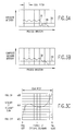
- Figs. 2A - 2B illustrate the exposure of a typical xerographic photoreceptor, such as the photoreceptor 14 (Fig. 1), to a step function that is oriented in the process direction, when the printing is performed by scanning a generally circular scan spot having a gaussian intensity profile over the photoreceptor in accordance with a scan pattern having a pitch approximately equal to the FWHM diameter of the scan spot.
- the step function is a typical image transition, which is defined by (a) a series of full intensity scans (the exposure caused by them is shown in Fig. 2A at 35), followed by (b) a single intensity modulated transitional or "boundary" scan as at 36 in Fig.
- Fig. 2B demonstrates that the superpositioning of the discrete exposures that result from such a sequence of scans causes the exposures to additively combine, thereby producing a composite exposure profile 38 that crosses the xerographic threshold 39 of the photoreceptor 14 at a position which spatially varies as a function of the intensity of the boundary scan 36 (for illustrative purposes, the xerographic threshold 39 is depicted as being at about one half the peak level of the composite exposure profile 38) Fig.
- 2C shows that there is a non-linearity of about ⁇ 15% in the relationship between the intensity of the boundary scan 36 and the spatial positioning of the point at which the exposure profile 38 crosses the xerographic threshold 39 (i. e., the spatial position of the image transition).
- Figs. 3A - 3C provide the same analysis as Figs. 2A - 2C, respectively, for a case in which the scan pitch is selected to be approximately 1.25 times the FWHM diameter of the scan spot.
- Fig. 3C indicates that the non-linearity in the relationship between the intensity of the boundary scan 36 (Fig. 3A) and the spatial positioning of the point at which the exposure profile 38 (Fig. 38) crosses the xerographic threshold 39 is nonmonotonic.
- a relatively coarse scan pitch is unattractive when the goal is to provide increased control over the spatial positioning of the image transitions.
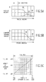
- Figs. 4A - 4C, 5A - 5C, and 6A - 6C extend the analysis of Figs. 2A - 2C to cases in which the scan pitch is selected to be approximately 0.75, 0.50 and 0.25 times the FWHM diameter of the scan spot, respectively.
- These cases demonstrate that the relationship between the intensity of the boundary scan 36 and the spatial positioning of the point at which the exposure profile 38 crosses the xerographic threshold 39 of the photoreceptor 14 becomes increasingly linear as the ratio of scan pitch to the FWHM diameter of the scan spot is reduced to progressively smaller, sub-unity values.
- the boundary scan intensity/exposure boundary position relationship is linear to within: (1) about ⁇ 7% when the scan pitch is three quarters of the FWHM diameter of the scan spot (Fig. 4C), (2) about ⁇ 3% when the scan pitch is one half of the FWHM diameter (Fig. 5C), and (3) about ⁇ 1% when the scan pitch is one quarter of the FWHM diameter (Fig. 6C).
- a limited overscan is, however, consistent with the printing of high quality images because it permits the image transitions (i. e., the high spatial frequency content of the images) to be mapped onto the scan pattern with increased spatial precision.
- the multi-bit data values that are supplied by the data source 23 are modulated (by means not shown) so that each of the image transitions is represented by a data value that is substantially linearly proportional to the desired spatial offset (in predetermined sub-scan pitch units) of the transition from the nearest "macroaddressed" exposure boundary position (i. e., the spatial location at which the composite exposure profile 38 (Figs. 4B, 5B and 6B) would cross the xerographic threshold 39 if the boundary scan 36 had a null or zero intensity level).
- This data modulation causes a corresponding intensity modulation of the laser beam 13, thereby permitting the spatial positioning of the exposure boundaries that define the image transitions (i.
- the microaddressability of the printer 11 is largely dependent upon the granularity at which the data values for the boundary scans specify the desired exposure boundary offsets. For example, if three bit long data values are supplied, five of the eight available digital values suitably are used for controlling the positioning of the exposure boundaries in 25% increments over a span equal to the scan pitch (i. e., a positional granularity of one quarter of a scan pitch), from a "full left” or 0% offset position to a "full right” or 100% offset position (see Fig. 7A).
- the scan pitch i. e., a positional granularity of one quarter of a scan pitch
- the data value for any given boundary scan can be selected to spatially offer the position of the corresponding exposure boundary (or, in other words, image transition) from the nearest macroaddressed boundary position by 0%, 25%, 50%, 75%, or 100% of the scan pitch.
- the data values for the boundary scans may be precompensated (by means not shown) to compensate for any residual non-linearity of the addressability response (i. e., the boundary scan intensity/exposure boundary position relationship) of the printer 11 at the selected scan pitch.
- This precompensation provides the data values that are needed to cause the actual spatial positioning of the transitions to even more closely track the desired positioning (as shown, for example in Fig 4C, the compensating intensity adjustment is given by the difference between the actual addressability response curve 40a and the linear approximation thereof 40b).
- the need for this precompensation is avoided by using a scan pitch that is sufficiently fine to permit the positioning errors that are caused by this non-linearity to be ignored.
- a variety of known techniques may be employed for reducing the scan pitch of a more or less conventional xerographic printer, such as printer 11 (Fig. 1). For instance, the angular velocity of the scanner 17 can be increased, the linear velocity at which the photoreceptor 14 is advanced can be decreased, and/or the number of scan spots that are used can be increased.
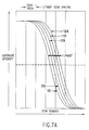
- Fig. 7A illustrates the microadaressability that can be built into a more or less conventional 400 d. p. i. laser xerographic print engine by substituting a quadspot laser (i. e., a laser that supplies four independently modulable, parallel output beams) for the single beam laser that is ordinarily used in such a print engine. This change reduces the scan pitch from 1/400" to 1/1600".
- a quadspot laser i. e., a laser that supplies four independently modulable, parallel output beams
- each of the four scan spots of such a quadspot printer suitably is selected to have a FWHM diameter of approximately 1/800" (i e., twice the scan pitch) to provide a 2x overscan of the photoreceptor.
- the four parallel laser beams are independently modulated in accordance with respective streams of, say, three bit long data values, thereby providing sufficient microaddressability for spatially offsetting image transitions from the macroaddressable exposure boundaries by 0%, 25%, 50%, 75%, or 100% of the scan pitch, as previously described. As shown in Fig.
- a quadspot printer that conforms to the foregoing specifications is able to control the spatial positioning of the exposure boundaries/image transitions in the images that it prints to a precision of about 1/6400' in the process direction.
- the slope at which the composite exposure profile 38 crosses the xerographic threshold 39 in such a printer does not significantly vary as a function of the boundary scan intensity, so the microaddressability of the printer is substantially unaffected by the usual tendency of its xerographic threshold 39 to shift upwardly and downwardly by relatively small amounts as a function of the ambient operating conditions (i. e., temperature, humidity, etc.).
- Fig. 7B illustrates the comparable performance of a non-overscanned printer that uses, for example, a 1/800" scan spot and a scan pattern having a pitch of 1/800".
- the drive current for the laser diode 15 is serially modulated in accordance with the data values that are clocked out of the data source 23, thereby intensity modulating the laser beam 13 at the data clock rate in accordance with those data values.
- a digital duty cycle modulator 41 can be employed for driving the laser 13 with current pulses that are duty cycle modulated in accordance with such multi-bit data values.
- a digital-to-analog (D/A) converter 42 (Fig. 8) could be employed for converting the multi-bit digital data values into corresponding analog signal levels.
- the analog control signal that is provided by the D/A converter 42 is applied to an amplitude modulator 43 for amplitude modulating the drive current for the laser 15 (and, thus, the amplitude of the laser beam 13) in accordance with the data values.
- intensity modulated boundary exposures can be employed to provide substantially linear, sub-resolution control over the spatial positioning of image transitions in exposure profiles that are composed by printing multiple, superpositioned. discrete exposures on a high gamma, photosensitive recording medium, provided that the center-to-center spacing of the exposures is significantly less than the effective diameter of the footprint of the radiation to which the recording medium is exposed (i. e., the FWHM diameter of the incident print spot if the printing is performed by a gaussian spot).
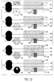
- the present invention can be applied to optical image bars, such as the LED image bar that is shown in Fig. 9 at 51, for increasing the transverse precision with which these image bars spatially position image transitions in images they print on high gamma recording media, such as the xerographic photoreceptor 52.
- the image bar 51 is composed of a linear array of individually addressable LED's 53 that are distributed widthwise of the photoreceptor 52 on generally uniformly spaced centers for sequentially exposing the photoreceptor 52 to successive lines of an image as the photoreceptor 52 is being advanced (by means not shown) in an orthogonal process direction.
- the image bar 51 is projected onto the photoreceptor 52 by suitable projection optics 54, such as an array of SELFOC (self-focusing) lenses.
- suitable projection optics 54 such as an array of SELFOC (self-focusing) lenses.
- it could be imaged onto the photoreceptor 52 at a predetermined magnification by imaging optics (not shown).
- each of the line-like exposure profiles that the image bar 51 prints on the photoreceptor 52 is composed of multiple, superpositioned, discrete exposures that have contrast levels which vary in accordance with the output intensities of the respective LED's by which they were printed.
- the projection optics 54 or the imaging optics ) are designed to cause the center-to-center spacing of these superpositioned exposures to be substantially less than the effective diameter of the individual print spots that are produced by the LEDs.
- This provides the microaddressability that enables the spatial positioning of the transitions in the images that the image bar 51 is printing to be controlled to a sub-resolution precision lengthwise of the array of LEDs 53 by intensity modulating the light beams that are emitted by the individual LEDs 53 to expose the photoreceptor 52 to appropriately modulated boundary scans.
- the location of a transition in the process direction may be microaddressed by printing the printed lines in the vicinity of the transition with a predetermined and appropriate intensity or exposure level.
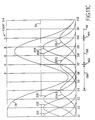
- Figs. 5A-5C show a process direction impulse response of a printer having a partial intensity boundary scan and a pitch distance of 50 times the FWHM diameter of the scan spot
- the boundary scan is shown at 36
- the composite of the remaining scans is shown at 35
- the xerographic threshold is shown at 39
- the remaining scans are exposed at full intensity.
- Boundary scan 36 is exposed at a partial intensity which is so weak that alone it would not cross the xerographic threshold, thus alone it would not cause printing to occur.
- the composite of the remaining scans 35 which does not include boundary scan 36 is the result of a sequence of full intensity scans extending to and ending with the scan immediately preceding (in Fig. 5A, to the left of) the boundary scan 36. Due to the generally bell-shaped nature (describable as a Gaussian curve) of the exposure pattern in the process direction of a single scan, the exposure pattern of the composite of the remaining scans 35 tapers off to cross the xerographic threshold 39 at a point midway between the center lines of two adjacent scans, thus only printing at locations to the left (in Fig. 5A) of the threshold crossing.
- the exposure profile 38 (Fig 5B), formed as a composite of the boundary scan 36 (Fig. 5A) and the composite of the remaining scans 35 (Fig. 5A), crosses the xerographic threshold at a process direction location to the right (in Figs. 5A and 5B) of the location at which the composite of the remaining scans 35 (Fig. 5A) crosses the threshold.
- the partial boundary scan 36 (Fig. 5A) "influences" the location at which the exposure profile 38 (Fig. 5B) crosses the xerographic threshold 39, and therefore, "influences" the location at which an edge will be printed.
- the edge may be relocated within a small range and in small increments in the process direction by controlling the intensity of the boundary scan 36 (Fig.
- the edge to be printed can be microaddressed in the process direction.
- the addressability in the process direction is based on the number of intensity steps (i.e., the size of each individual intensity step) producible by the writing device.
- FIG. 10 an example of how the writing device may be intensity modulated to microaddress the location of an edge to be produced.
- a writing device such as a scanning laser spot or a light emitting diode spot, writes an exposure (i.e., a print bit) that is combined with exposures from previous or adjacent scans.
- the exposure of a boundary scan can be illustrated as having a predetermined size, for example the size shown as the circles depicted at 100-108.
- the writing device intensity modulates the spot intensity to produce various exposure levels. For example, in Fig. 10 spots 100-108 are produced by intensity modulating the writing device at respective intensity levels I0-I4. Note that the boundary scan is indicated on scan line 142.
- Fig. 10 Two adjacent and prior scans are indicated on scan lines 144 and 146 so that the boundary scan overlaps the adjacent scan by a pitch distance equal to 50 times the FWHM.
- the adjacent spots are shown at 110.
- One or more adjacent spots are written at full (100%) intensity.
- the combination of the exposures of the boundary scan spot and the adjacent scan spots produce an exposure profile in the process direction having a transition where the exposure profile crosses the xerographic threshold as indicated at 120-128.
- Transition 124 corresponds to the transition indicated in Fig. 5B of exposure profile 38 across the xerographic threshold 39 with boundary scan intensity set to I2.
- transition 120 corresponds to the transition in Fig.
- the writing device is intensity modulated to produce five intensity values from I0-I4, that is to say four intensity steps.
- spot 100 is intensity modulated at intensity I0
- transition 120 occurs at two microaddress steps above (in Fig. 10) the center line 142 of the boundary scan.
- spot 102 is intensity modulated at intensity I1
- the transition 122 occurs at 1 microaddress above the center 142 of the boundary scan.
- spot 104 is intensity modulated at intensity I2
- transition 124 occurs at the center of the boundary scan 142
- transition 126 occurs one microaddress step below (in Fig. 10) the center line of the boundary scan 142.
- the transition 128 occurs at two microaddress steps below the center of the boundary scan 142.
- the transition may,controlled between transition 120 and 128 in microaddress steps indicated at 140.
- Figs. 11A-11C illustrate a particular case of an edge and a feature line being printed.
- the center of individual scans are shown at S1-S12.
- the exposure profile in the process direction produced by a writing device writing with maximum intensity is shown by profile 201-203 corresponding to scans S1-S3, respectively.
- profile 202 extends from the center line of scan S1 to the center line of scan S3, thus defining the size of the FWHM.
- scan profile 202 follows scan profile 201 and is separated in the process direction by a pitch distance equal to one-half of the FWHM.
- scan profile 203 is separated from scan profile 202 by the same pitch distance.
- any individual scan profile 201-203 is less than the xerographic threshold 39. That is to say, any individual scan 201- 203, taken alone, will be unable to exceed the xerographic threshold 39 and write.
- the composite exposure profile 38 indicates that, taken together, the exposure profiles in the process direction well exceed the xerographic threshold 39 at the center of scans S1-S3 until a transition occurs at a point midway between the center of scans S3 and S4.
- Fig. 11B exposure profiles 201-203 are written at full intensity and a new exposure profile 204-1 is created for scan S4 at intensity level I1.
- the addition of exposure profile 204-1 moves the composite profile 38 to the right (in Fig. 11B) by an amount equal to one-fourth of the pitch distance (referred to as one microaddress step).
- Fig. 11C scan 54 is modulated at intensity I2 to produce exposure profile 204-2. This increased intensity of scan S4 further moves the transition to the right (in Fig. 11C) where composite exposure profile 38 crosses the xerographic threshold 39.
- Figs. 11A-11C also illustrate the printing process for printing a feature or raster line.
- the writing device is intensity modulated while scanning through scans S7-S10.
- the writing device is intensity modulated at intensity I4 to produce exposure profile 207-4 during scan S7; and also is intensity modulated at intensity level I4 during scans S8 and S9 to produce exposure profiles 208 and 209.
- the composite exposure profile 38 shows the xerographic threshold 39 being crossed at a point midway between the center of scans 56 and S7, and being crossed again at a point midway between the center of scans S9 and S10.
- raster lines 159, 160 and 161 are shown with respect to scan lines with writing intensities which could cause an exposure to write raster line 160. Note that the raster lines are phase shifted with respect to the center of the scans by two addressability units between Figs. 11A and 11C.
- the writing device is intensity modulated at intensity I3 during scan 57 and intensity modulated at intensity I1 during scan S10 to produce scan profiles 207-3 and 210-1 centered about the center of scan S7 and S10, respectively.
- the writing device is modulated at intensity I4 during scans S8 and S9 to produce exposure profiles 208 and 209.
- the two transition points where the composite exposure profile 38 crosses the xerographic threshold 39 in Fig. 11B is shifted to the right by one microaddress step (one quarter of the pitch distance). This shift is illustrated by a right shift of one addressability unit of raster lines 159, 160 and 161. Note that the raster line width of raster line 160 remains the same.
- the writing device is intensity modulated at intensity I2 during scans 57 and S10 to produce exposure profiles 207-2 and 210-2.
- the two transitions where composite exposure profile 38 crosses the xerographic threshold 39 are thus moved to the right (in Fig. 11C) by an additional microaddress step (when compared to Fig. 11B). This again is illustrated by the raster lines 159-161.
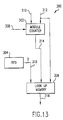
- a printer capable of producing an image raster line 160 as shown in Figs. 11A-11C has a print intensity controller 300 as shown in Figure 13.
- the print intensity controller is concerned with producing a print intensity signal to drive the writing device according to the current image bit and an adjacent image bit.
- the First In First Out (FIFO) buffer 304 ( Figure 13) contains two image raster lines of data: a current image raster line (i.e., the image raster line through which the center of the current scan line passes) and an adjacent image raster line.
- Each image raster line includes data brganized in a series of image bits.
- the current image bit may be in either a first or a second state and the adjacent image bit may be in either a first or a second state.
- a first state indicates that the image bit is to be fully written (ON) and a second state indicates that the image bit is to remain unwritten (OFF).
- print intensity controller 300 includes modulo counter 302, First In First Out (FIFO) buffer 304 and look up memory 306 (for example, a read only memory or a PROM).
- the modulo counter is incremented for each scan of the writing device upon the occurrence of a counter clock 308.
- the modulo increment value 312 is the number of intensity steps that extend across a pitch distance in the process direction (to be referred to as L), that is to say the number of intensity values less 1. In the example shown in Figure 10, there are five intensity values and four intensity steps.
- the modulo counter modulo counts according to a modulo base (or a modulus, M) 310.
- the modulo base is the number of sub-addresses per image raster width. For example, in Figs. 11A-11C an image raster line is twelve microaddress steps wide between left edge 162 and right edge 164. Therefore, modulo base 310 would be twelve to produce the line width depicted in Figs. 11A-11C. It is easy to see how a larger modulo base will produce a wider raster line width, or a smaller modulo base will produce a narrower raster line width.
- the modulo counter is incremented before the beginning of each scan according to counter clock 308 by the amount of the modulo increment value 312. If the modulo counter equals or exceeds its modulus, it resets itself to the amount by which it exceeds its modulus, thereby always having a count that varies from 0 to its modulus-1.
- the output of modulo counter 302 is a offset value 314 which can be used as a measure of where an image transition or raster edge is to be printed relative to the center of the current scan. This is illustrated in Figs. 11A-C where the offset value 314 is indicated at the top of each scan. In Fig.
- S6 through S10 have values 10, 2, 6, 10, 2, as indicated, assuming the transitions between rasters at 162 and 164 are indicated by a zero value in the counter. If that is the case, then the same scans in Fig. 11B would have values 9, 1, 5, 9, 1, and for Fig 11C the values would be 8, 0, 4, 8, 0, in keeping with the phase shift of the image rasters.
- the look up memory receives the offset value 314 to determine the location of the image transition.
- the look up memory also receives the modulo increment value 312 to determine the number of sub-address steps that may be implemented by appropriately intensity modulating the writing device.
- the look up memory receives the current and adjacent image bits from the First In First Out buffer 304.
- the look up memory 306 has all inputs necessary to determine the required intensity modulation signal 318 necessary to achieve sub-addressability as illustrated in Figs. 11A-11C.
- the look up memory may be any suitable memory, including a read only memory or a PROM. Although the look up memory provides a digital output signal indicative of the required intensity signal, it will be appreciated that the digital output signal may be easily converted into an analog output signal to intensity modulate the writing device.
- a transition in the process direction may be positioned to a per inch accuracy of one part in 4800, 6000, 7200 and 8400 (referred to as addressable steps per inch, A), when the number of intensity steps produced by the writing device is 4, 5, 6 and 7 respectively. That is to say 4, 5, 6 and 7 intensity steps multiplied by 1200 scans per inch produces addressability of 4800, 6000. 7200 and 8400, respectively.
- Image data comprising image raster lines of various widths may be easily produced using the modulo counter.
- Table 2 indicates the output resolution as a function of the addressable steps per inch and the modulo base. For example, for 4800 addressability, it shows the output resolution varying from 141 to 480 rasters per inch.
- the resolution of image data sent to a printer need not exactly match the scans per inch of the printer. Instead, the print intensity controller adjusts microaddressability by the controller to achieve integer resolution conversion from any image data resolution to the scans per inch of the printer.
- the resolution in the fast scan direction may be adjusted by clock frequency.
- the modulo counter may be an accumulator or counter. It will be understood that print intensity modulation to produce various intensity valves may be achieved by many techniques including (1) constant intensity pulses with varying pulse durations, (2) constant intensity pulse groups with a varying number pulses per group (each pulse of constant or varying duration), (3) varying intensity pulses (i.e., the drive voltage and/or current varies), or (4) any combination to the required intensity value.
- Figure 12 is a graph of an addressability response curve for the print intensity controller of Figure 13.
- the vertical axis of the graph is the print intensity required from the writing device which ranges from full off to full on.
- the horizontal axis is the print centerline distance from the desired transition edge.
- the horizontal axis is centered at zero and extends from -L/2 through + L/2. If the centerline of the current scan is at a distance from the desired transition edge that is greater than or equal to L/2 (where L is the pitch distance) then the writing device will be written with either a full on or a full off intensity depending on which side of the transition edge is being written.
- the writing device When the centerline of the writing device is within a distance of L/2 of the desired transition edge, the writing device writes at an intensity greater than full of (zero intensity) and less than full on (maximum intensity), according to the addressability response curve. For example, when the centerline of the writing device (i.e., the scan line) coincides with the transition edge (as depicted at 172 or 177), the displacement distance of the centerline from the transition edge is zero. Therefore, in accordance with Figure 12, the writing device. is written with an intensity halfway between full on and full off.
- the bottom horizontal edge of the graph depicts marks 170-174 separated by one quarter of the pitch distance (corresponding to the value L), corresponding to four intensity steps such that the distance between adjacent ones of each of the marks 170-174 correspond to one microaddress step.
- the centerline of the writing device i.e., the scan center line
- the writing device is driven to produce an intensity value corresponding to one quarter or zero, respectively, of the full on intensity value.
- the centerline of the writing device is one or two microaddress steps to the right of the zero reference indicating the transition edge (as depicted at 173 and 174, respectively) then the writing device.
- the writing device centerline is one or two steps to the left of the zero reference transition edge (as depicted at 176 and 175, respectively)
- the writing device is driven to produce an intensity value corresponding to 30% and 10% of the full on intensity value, respectively.
- the writing device centerline is one or two microaddress steps to the right of the zero reference line (as depicted at 178 and 179, respectively)
- the writing device is driven to produce an intensity value equal to 70% or 90% of the full on intensity value, respectively.
- the intensity value evaluated according to the vertical axis in Figure 12 is the required intensity modulation signal output from the look-up memory 306. It will be appreciated that other means, in addition to a look-up memory may be employed to produce the intensity modulation signal 318, although a look-up memory is a convenient and low cost means given the digital input signal representing offset value 314 derived from modulo counter 302, the digital output from First In First Out buffer 304 and the modulo increment value 312 in digital form.
- the present invention provides relatively inexpensive and easily implemented methods and means for increasing the spatial addressability of printers and other optical display systems that render images on high gamma, photosensitive recording apparatus.
- These rendering systems are operated in an overscanned mode to provide the microaddressability that enables them to utilize intensity modulated boundary scans for substantially linearly controlling the spatial positioning of the transitions that are contained by the images they are rendering to a sub-resolution precision.
- the contrast, pitch grating and phase shift of the composite light intensity profile can be determined by the amount of overlap between near-neighbor laser beam spots, intensity profile of the laser beam spots and intensity of each of the plurality of parallel laser beam spots.
Abstract
Description
| IMAGE RASTER RESOLUTION, D | ||||
| Addressable Steps Per Inch | ||||
| Modulo base M | 4800 | 6000 | 7200 | 8400 |
| 50 | 144 | 168 | ||
| 49 | 147 | 171 | ||
| 48 | 150 | 175 | ||
| 47 | 153 | 179 | ||
| 46 | 157 | 183 | ||
| 45 | 160 | 187 | ||
| 44 | 167 | 191 | ||
| 43 | 167 | 195 | ||
| 42 | 143 | 171 | 200 | |
| 41 | 146 | 176 | 205 | |
| 40 | 150 | 180 | 210 | |
| 39 | 154 | 185 | 215 | |
| 38 | 158 | 189 | 221 | |
| 37 | 162 | 195 | 227 | |
| 36 | 167 | 200 | 233 | |
| 35 | 171 | 206 | 240 | |
| 34 | 141 | 176 | 212 | 247 |
| 33 | 145 | 182 | 218 | 255 |
| 32 | 150 | 188 | 225 | 263 |
| 31 | 155 | 194 | 232 | 271 |
| 30 | 160 | 200 | 240 | 280 |
| 29 | 166 | 207 | 248 | 290 |
| 28 | 171 | 214 | 257 | 300 |
| 27 | 178 | 222 | 267 | 311 |
| 26 | 185 | 231 | 277 | 323 |
| 25 | 192 | 240 | 288 | 336 |
| 24 | 200 | 250 | 300 | 350 |
| 23 | 209 | 261 | 313 | 365 |
| 22 | 218 | 273 | 327 | 382 |
| 21 | 229 | 286 | 343 | 400 |
| 20 | 240 | 300 | 360 | 420 |
| 19 | 253 | 316 | 379 | 442 |
| 18 | 267 | 333 | 400 | 467 |
| 17 | 282 | 353 | 424 | |
| 16 | 300 | 375 | 450 | |
| 15 | 320 | 400 | 480 | |
| 14 | 343 | 429 | ||
| 13 | 369 | 462 | ||
| 12 | 400 | |||
| 11 | 436 | |||
| 10 | 480 |
Claims (3)
- A method for resolution conversion from print data of an image to be printed to scan line data for a printer, the print data comprising a plurality of print lines having a first pitch distance between print line transitions, the scan line data comprising a plurality of scan lines to be printed by the printer, each scan line having a center line, the center lines of adjacent scan lines separated by a second pitch distance less than the first pitch distance, the printer capable of microaddressing the print line transitions by modulating intensities of light spots forming the scan lines at a plurality of intensity level steps to microaddress the positions of the print line transitions, where a composite intensity of a plurality of scan lines crosses a xerographic threshold, relative to the center lines of the scan lines, the method comprising, for each scan line:determining, for that scan line, a separation distance from the center of that scan line to a nearest print line transition;modulating, when the separation distance is equal to or greater than one-half the second pitch distance, the intensity of the light spot forming that scan line based on the image data for a print line through which the center line of that scan line passes and independently of the separation distance; andmodulating, when the separation distance is less than one-half the second pitch distance, the intensity of the light spot forming that scan line based on the image data for the print line through which the center line of that scan line passes, the image data for an adjacent print line closest to the center line of that scan line, and the separation distance, further comprising phase shifting the print line transitions relative to the center lines of the scan lines.
- The method of claim 1, wherein phase shifting the print lines transitions comprises changing the separation distance of the center line of a reference scan line relative to a reference print line transition.
- A method of controlling a pitch grating of a composite exposure profile and phase shifting a spatial location at which the composite exposure profile crosses a xerographic threshold in a printer, the printer having two or more laser beams for forming the light spots and a photosensitive medium, the method comprising:driving the printer in accordance with claim 1, the step of modulating the scan lines comprising intensity modulating each of the laser beams; anddirecting the laser beams onto the photosensitive medium to form the light spots on the photosensitive medium, each light spot having a predetermined area, exposure profile and intensity range, the predetermined area of each light spot overlapping that of adjacent light spots by a predetermined overlap area within the second pitch distance to form the composite exposure profile, the pitch grating and phase shifting determined by at least one of the predetermined overlap area, exposure profile and intensity range of each of the laser beams.
Applications Claiming Priority (3)
| Application Number | Priority Date | Filing Date | Title |
|---|---|---|---|
| US918092 | 1992-07-24 | ||
| US07/918,092 US5357273A (en) | 1991-07-29 | 1992-07-24 | Resolution conversion via intensity controlled overscanned illumination for optical printers and the like having high gamma photosensitive recording media |
| EP93305655A EP0580388B1 (en) | 1992-07-24 | 1993-07-19 | Method and apparatus for enhanced resolution and contrast via super intensity controlled overscanned illumination in a two dimensional micro-addressability printer |
Related Parent Applications (2)
| Application Number | Title | Priority Date | Filing Date |
|---|---|---|---|
| EP93305655.8 Division | 1993-07-19 | ||
| EP93305655A Division EP0580388B1 (en) | 1992-07-24 | 1993-07-19 | Method and apparatus for enhanced resolution and contrast via super intensity controlled overscanned illumination in a two dimensional micro-addressability printer |
Publications (3)
| Publication Number | Publication Date |
|---|---|
| EP0893780A2 true EP0893780A2 (en) | 1999-01-27 |
| EP0893780A3 EP0893780A3 (en) | 2005-03-16 |
| EP0893780B1 EP0893780B1 (en) | 2011-04-20 |
Family
ID=25439791
Family Applications (2)
| Application Number | Title | Priority Date | Filing Date |
|---|---|---|---|
| EP98119941A Expired - Lifetime EP0893780B1 (en) | 1992-07-24 | 1993-07-19 | Method for resolution conversion of print data for a printer |
| EP93305655A Expired - Lifetime EP0580388B1 (en) | 1992-07-24 | 1993-07-19 | Method and apparatus for enhanced resolution and contrast via super intensity controlled overscanned illumination in a two dimensional micro-addressability printer |
Family Applications After (1)
| Application Number | Title | Priority Date | Filing Date |
|---|---|---|---|
| EP93305655A Expired - Lifetime EP0580388B1 (en) | 1992-07-24 | 1993-07-19 | Method and apparatus for enhanced resolution and contrast via super intensity controlled overscanned illumination in a two dimensional micro-addressability printer |
Country Status (4)
| Country | Link |
|---|---|
| US (1) | US5357273A (en) |
| EP (2) | EP0893780B1 (en) |
| JP (1) | JPH0691929A (en) |
| DE (2) | DE69334355D1 (en) |
Cited By (1)
| Publication number | Priority date | Publication date | Assignee | Title |
|---|---|---|---|---|
| EP1293348A2 (en) * | 2001-09-17 | 2003-03-19 | Fuji Photo Film Co., Ltd. | Image recording method and image recording apparatus |
Families Citing this family (10)
| Publication number | Priority date | Publication date | Assignee | Title |
|---|---|---|---|---|
| US5666372A (en) * | 1989-12-26 | 1997-09-09 | United Technologies Corporation | Embedded Bragg grating laser master-oscillator and power-amplifier |
| US5973709A (en) * | 1992-06-24 | 1999-10-26 | Oki Electric Industry Co., Ltd. | Printer and process for printing different size dots by setting drive energies based on adjacent data bit logic |
| US5461411A (en) * | 1993-03-29 | 1995-10-24 | Texas Instruments Incorporated | Process and architecture for digital micromirror printer |
| US5455602A (en) * | 1993-03-29 | 1995-10-03 | Texas Instruments Incorporated | Combined modulation schemes for spatial light modulators |
| US5537223A (en) | 1994-06-02 | 1996-07-16 | Xerox Corporation | Rotating non-rotationally symmetrical halftone dots for encoding embedded data in a hyperacuity printer |
| US6129457A (en) * | 1997-07-01 | 2000-10-10 | Xerox Corporation | Resolution enhancement for a digital printing apparatus |
| DE19826986C2 (en) * | 1998-06-18 | 2003-03-27 | Heidelberger Druckmasch Ag | Calibration procedures for image recorders |
| US7898695B1 (en) | 2000-10-06 | 2011-03-01 | Lexmark International, Inc. | Method of compensating for electronic printhead skew and bow correction in an imaging machine to reduce print artifacts |
| CN100394788C (en) * | 2004-08-04 | 2008-06-11 | 精工爱普生株式会社 | Projector |
| US8208175B2 (en) * | 2005-04-13 | 2012-06-26 | Xerox Corporation | Blended error diffusion and adaptive quantization |
Citations (2)
| Publication number | Priority date | Publication date | Assignee | Title |
|---|---|---|---|---|
| JPS58148773A (en) * | 1982-03-02 | 1983-09-03 | Fujitsu Ltd | Electronic photograph printer |
| US4775896A (en) * | 1985-08-08 | 1988-10-04 | Konishiroku Photo Industry Co., Ltd. | Image recording apparatus |
Family Cites Families (17)
| Publication number | Priority date | Publication date | Assignee | Title |
|---|---|---|---|---|
| US4476474A (en) * | 1981-04-02 | 1984-10-09 | Canon Kabushiki Kaisha | Dot recording apparatus |
| US4437122A (en) * | 1981-09-12 | 1984-03-13 | Xerox Corporation | Low resolution raster images |
| US4460909A (en) * | 1981-12-18 | 1984-07-17 | International Business Machines Corporation | Method and apparatus for enhancing the resolution of an electrophotographic printer |
| US4544264A (en) * | 1984-05-17 | 1985-10-01 | International Business Machines Corporation | Fine line print enhancement |
| US4625222A (en) * | 1984-05-17 | 1986-11-25 | International Business Machines Corporation | Interacting print enhancement techniques |
| US4639789A (en) * | 1984-05-29 | 1987-01-27 | Xerox Corporation | Raster scanner variable-frequency clock circuit |
| US4622593A (en) * | 1984-05-29 | 1986-11-11 | Xerox Corporation | Polygon signature correction |
| US4860237A (en) * | 1984-08-03 | 1989-08-22 | Xerox Corporation | Scan linearity correction |
| EP0204094B2 (en) * | 1985-03-30 | 1998-08-19 | Hitachi, Ltd. | Scanning recording type printing method and apparatus for realizing the same |
| US4766560A (en) * | 1985-12-23 | 1988-08-23 | Xerox Corporation | Parallel/pipelined arithmetic variable clock frequency synthesizer |
| US4681424A (en) * | 1986-05-20 | 1987-07-21 | Ibm Corporation | Compensation for fine line prints |
| JP2525794B2 (en) * | 1987-02-27 | 1996-08-21 | 大日本スクリ−ン製造株式会社 | Halftone image recorder |
| US4847641A (en) * | 1988-08-16 | 1989-07-11 | Hewlett-Packard Company | Piece-wise print image enhancement for dot matrix printers |
| US4935891A (en) * | 1988-12-22 | 1990-06-19 | Xerox Corporation | Pseudo-random phase shifted arithmetic bit clock generators for digital printers |
| US4893136A (en) * | 1988-12-22 | 1990-01-09 | Xerox Corporation | Arithmetically computed motor hunt compensation for flying spot scanners |
| US5128698A (en) * | 1990-01-19 | 1992-07-07 | International Business Machines Corporation | Boldness control in an electrophotographic machine |
| US5138339A (en) * | 1991-07-29 | 1992-08-11 | Xerox Corporation | Microaddressability via overscanned illumination for optical printers and the like having high gamma photosensitive recording media |
-
1992
- 1992-07-24 US US07/918,092 patent/US5357273A/en not_active Expired - Lifetime
-
1993
- 1993-06-25 JP JP5154813A patent/JPH0691929A/en active Pending
- 1993-07-19 DE DE69334355T patent/DE69334355D1/en not_active Expired - Lifetime
- 1993-07-19 EP EP98119941A patent/EP0893780B1/en not_active Expired - Lifetime
- 1993-07-19 DE DE69326646T patent/DE69326646T2/en not_active Expired - Lifetime
- 1993-07-19 EP EP93305655A patent/EP0580388B1/en not_active Expired - Lifetime
Patent Citations (2)
| Publication number | Priority date | Publication date | Assignee | Title |
|---|---|---|---|---|
| JPS58148773A (en) * | 1982-03-02 | 1983-09-03 | Fujitsu Ltd | Electronic photograph printer |
| US4775896A (en) * | 1985-08-08 | 1988-10-04 | Konishiroku Photo Industry Co., Ltd. | Image recording apparatus |
Non-Patent Citations (1)
| Title |
|---|
| PATENT ABSTRACTS OF JAPAN vol. 007, no. 269 (M-259), 30 November 1983 (1983-11-30) & JP 58 148773 A (FUJITSU KK; others: 01), 3 September 1983 (1983-09-03) * |
Cited By (3)
| Publication number | Priority date | Publication date | Assignee | Title |
|---|---|---|---|---|
| EP1293348A2 (en) * | 2001-09-17 | 2003-03-19 | Fuji Photo Film Co., Ltd. | Image recording method and image recording apparatus |
| EP1293348A3 (en) * | 2001-09-17 | 2003-04-23 | Fuji Photo Film Co., Ltd. | Image recording method and image recording apparatus |
| US7212225B2 (en) | 2001-09-17 | 2007-05-01 | Fujifilm Corporation | Enhanced resolution image recording method and enhanced resolution image recording apparatus |
Also Published As
| Publication number | Publication date |
|---|---|
| DE69326646T2 (en) | 2000-03-16 |
| EP0893780A3 (en) | 2005-03-16 |
| DE69334355D1 (en) | 2011-06-01 |
| EP0580388A1 (en) | 1994-01-26 |
| JPH0691929A (en) | 1994-04-05 |
| EP0893780B1 (en) | 2011-04-20 |
| DE69326646D1 (en) | 1999-11-11 |
| EP0580388B1 (en) | 1999-10-06 |
| US5357273A (en) | 1994-10-18 |
Similar Documents
| Publication | Publication Date | Title |
|---|---|---|
| EP0526000B1 (en) | Microaddressability via overscanned illumination for optical printers and the like having high gamma photosensitive recording media | |
| EP0605131B1 (en) | Method and apparatus for eliminating distortion via overscanned illumination for optical printers and the like having high gamma photosensitive recording media and high addressability | |
| EP0549314B1 (en) | Enhanced fidelity reproduction of images by hierarchical template matching | |
| CA2129722C (en) | Hyperacuity printer architecture | |
| EP0651560A2 (en) | Halftoning in a hyperacuity printer | |
| EP0854636B1 (en) | Hierarchical template-matching filters | |
| JP2000032266A (en) | Half-tone hybrid screen generating device | |
| US5426519A (en) | Method and apparatus for implementing accurate angle screens | |
| US6816269B1 (en) | Method and apparatus for electronic registration in a binary image path | |
| US6519055B1 (en) | Two-dimensional linear interpolation and registration control for a hyperacuity printer | |
| US5283658A (en) | Image forming apparatus with TTL to ECL conversion between reading and printing circuits | |
| EP0580388B1 (en) | Method and apparatus for enhanced resolution and contrast via super intensity controlled overscanned illumination in a two dimensional micro-addressability printer | |
| US6346993B1 (en) | Tone-variation-resistant phase-shiftable halftone screen system and method of using | |
| US5367381A (en) | Method and apparatus for enhanced resolution and contrast via super intensity controlled overscanned illumination in a two dimensional high addressability printer | |
| EP1426900B1 (en) | Image forming apparatus with resolution conversion | |
| EP0794656B1 (en) | Adjustment of dot size for laser imagers | |
| US6985627B2 (en) | LED bar array high addressable imaging in 2-dimensions | |
| US5740330A (en) | Exposure controlling method and an exposure controlling apparatus | |
| USRE40170E1 (en) | Multi-tone image processing method and apparatus | |
| US5321433A (en) | Electrophotographic printing apparatus with enhanced printed image capability | |
| US6201560B1 (en) | Multibeam modulation driver for a hyperacuity printer | |
| JPH0691930A (en) | Method and device for improving resolution and contrast of optical printer | |
| JP3419502B2 (en) | How to remove optical printer distortion | |
| EP0425698B1 (en) | Image forming apparatus | |
| WO1995033330A1 (en) | Technique for rendering images on a binary marking engine |
Legal Events
| Date | Code | Title | Description |
|---|---|---|---|
| PUAI | Public reference made under article 153(3) epc to a published international application that has entered the european phase |
Free format text: ORIGINAL CODE: 0009012 |
|
| AC | Divisional application: reference to earlier application |
Ref document number: 580388 Country of ref document: EP |
|
| AK | Designated contracting states |
Kind code of ref document: A2 Designated state(s): DE FR GB |
|
| PUAL | Search report despatched |
Free format text: ORIGINAL CODE: 0009013 |
|
| AK | Designated contracting states |
Kind code of ref document: A3 Designated state(s): DE FR GB |
|
| 17P | Request for examination filed |
Effective date: 20050916 |
|
| GRAP | Despatch of communication of intention to grant a patent |
Free format text: ORIGINAL CODE: EPIDOSNIGR1 |
|
| GRAS | Grant fee paid |
Free format text: ORIGINAL CODE: EPIDOSNIGR3 |
|
| GRAA | (expected) grant |
Free format text: ORIGINAL CODE: 0009210 |
|
| AC | Divisional application: reference to earlier application |
Ref document number: 0580388 Country of ref document: EP Kind code of ref document: P |
|
| AK | Designated contracting states |
Kind code of ref document: B1 Designated state(s): DE FR GB |
|
| REG | Reference to a national code |
Ref country code: GB Ref legal event code: FG4D |
|
| REF | Corresponds to: |
Ref document number: 69334355 Country of ref document: DE Date of ref document: 20110601 Kind code of ref document: P |
|
| REG | Reference to a national code |
Ref country code: DE Ref legal event code: R096 Ref document number: 69334355 Country of ref document: DE Effective date: 20110601 |
|
| PGFP | Annual fee paid to national office [announced via postgrant information from national office to epo] |
Ref country code: FR Payment date: 20110727 Year of fee payment: 19 |
|
| PGFP | Annual fee paid to national office [announced via postgrant information from national office to epo] |
Ref country code: GB Payment date: 20110713 Year of fee payment: 19 Ref country code: DE Payment date: 20110713 Year of fee payment: 19 |
|
| PLBE | No opposition filed within time limit |
Free format text: ORIGINAL CODE: 0009261 |
|
| STAA | Information on the status of an ep patent application or granted ep patent |
Free format text: STATUS: NO OPPOSITION FILED WITHIN TIME LIMIT |
|
| 26N | No opposition filed |
Effective date: 20120123 |
|
| REG | Reference to a national code |
Ref country code: DE Ref legal event code: R097 Ref document number: 69334355 Country of ref document: DE Effective date: 20120123 |
|
| GBPC | Gb: european patent ceased through non-payment of renewal fee |
Effective date: 20120719 |
|
| REG | Reference to a national code |
Ref country code: FR Ref legal event code: ST Effective date: 20130329 |
|
| PG25 | Lapsed in a contracting state [announced via postgrant information from national office to epo] |
Ref country code: DE Free format text: LAPSE BECAUSE OF NON-PAYMENT OF DUE FEES Effective date: 20130201 Ref country code: FR Free format text: LAPSE BECAUSE OF NON-PAYMENT OF DUE FEES Effective date: 20120731 Ref country code: GB Free format text: LAPSE BECAUSE OF NON-PAYMENT OF DUE FEES Effective date: 20120719 |
|
| REG | Reference to a national code |
Ref country code: DE Ref legal event code: R119 Ref document number: 69334355 Country of ref document: DE Effective date: 20130201 |