EP0892330B1 - Environmental control system and method - Google Patents
Environmental control system and method Download PDFInfo
- Publication number
- EP0892330B1 EP0892330B1 EP98305564A EP98305564A EP0892330B1 EP 0892330 B1 EP0892330 B1 EP 0892330B1 EP 98305564 A EP98305564 A EP 98305564A EP 98305564 A EP98305564 A EP 98305564A EP 0892330 B1 EP0892330 B1 EP 0892330B1
- Authority
- EP
- European Patent Office
- Prior art keywords
- control
- controller
- control system
- air
- controllers
- Prior art date
- Legal status (The legal status is an assumption and is not a legal conclusion. Google has not performed a legal analysis and makes no representation as to the accuracy of the status listed.)
- Expired - Lifetime
Links
- 230000007613 environmental effect Effects 0.000 title claims description 16
- 238000000034 method Methods 0.000 title description 4
- 230000007704 transition Effects 0.000 claims description 59
- 238000001816 cooling Methods 0.000 claims description 37
- 238000010438 heat treatment Methods 0.000 claims description 37
- 230000000153 supplemental effect Effects 0.000 claims description 14
- 238000005304 joining Methods 0.000 claims description 3
- 230000004044 response Effects 0.000 claims description 3
- 238000010586 diagram Methods 0.000 description 17
- 230000009471 action Effects 0.000 description 7
- 238000011217 control strategy Methods 0.000 description 6
- 230000008901 benefit Effects 0.000 description 5
- 238000002156 mixing Methods 0.000 description 5
- 238000012163 sequencing technique Methods 0.000 description 5
- 230000008859 change Effects 0.000 description 4
- 230000000717 retained effect Effects 0.000 description 4
- XLYOFNOQVPJJNP-UHFFFAOYSA-N water Substances O XLYOFNOQVPJJNP-UHFFFAOYSA-N 0.000 description 4
- 230000003044 adaptive effect Effects 0.000 description 3
- 238000009826 distribution Methods 0.000 description 3
- 229920006395 saturated elastomer Polymers 0.000 description 3
- 238000003860 storage Methods 0.000 description 3
- 238000004378 air conditioning Methods 0.000 description 2
- 230000001143 conditioned effect Effects 0.000 description 2
- 230000003750 conditioning effect Effects 0.000 description 2
- 238000005516 engineering process Methods 0.000 description 2
- 238000009434 installation Methods 0.000 description 2
- 230000008569 process Effects 0.000 description 2
- 238000009423 ventilation Methods 0.000 description 2
- 239000002699 waste material Substances 0.000 description 2
- 241000396377 Tranes Species 0.000 description 1
- 230000001351 cycling effect Effects 0.000 description 1
- 230000001419 dependent effect Effects 0.000 description 1
- 230000000779 depleting effect Effects 0.000 description 1
- 238000005265 energy consumption Methods 0.000 description 1
- 238000001914 filtration Methods 0.000 description 1
- 238000011010 flushing procedure Methods 0.000 description 1
- 230000006870 function Effects 0.000 description 1
- 239000008236 heating water Substances 0.000 description 1
- 238000012423 maintenance Methods 0.000 description 1
- 230000004048 modification Effects 0.000 description 1
- 238000012986 modification Methods 0.000 description 1
- 238000004540 process dynamic Methods 0.000 description 1
- 239000007787 solid Substances 0.000 description 1
- 238000010792 warming Methods 0.000 description 1
Images




Classifications
-
- G—PHYSICS
- G05—CONTROLLING; REGULATING
- G05D—SYSTEMS FOR CONTROLLING OR REGULATING NON-ELECTRIC VARIABLES
- G05D23/00—Control of temperature
- G05D23/19—Control of temperature characterised by the use of electric means
- G05D23/1902—Control of temperature characterised by the use of electric means characterised by the use of a variable reference value
- G05D23/1904—Control of temperature characterised by the use of electric means characterised by the use of a variable reference value variable in time
-
- F—MECHANICAL ENGINEERING; LIGHTING; HEATING; WEAPONS; BLASTING
- F24—HEATING; RANGES; VENTILATING
- F24F—AIR-CONDITIONING; AIR-HUMIDIFICATION; VENTILATION; USE OF AIR CURRENTS FOR SCREENING
- F24F11/00—Control or safety arrangements
- F24F11/30—Control or safety arrangements for purposes related to the operation of the system, e.g. for safety or monitoring
-
- F—MECHANICAL ENGINEERING; LIGHTING; HEATING; WEAPONS; BLASTING
- F24—HEATING; RANGES; VENTILATING
- F24F—AIR-CONDITIONING; AIR-HUMIDIFICATION; VENTILATION; USE OF AIR CURRENTS FOR SCREENING
- F24F11/00—Control or safety arrangements
- F24F11/30—Control or safety arrangements for purposes related to the operation of the system, e.g. for safety or monitoring
- F24F11/46—Improving electric energy efficiency or saving
-
- F—MECHANICAL ENGINEERING; LIGHTING; HEATING; WEAPONS; BLASTING
- F24—HEATING; RANGES; VENTILATING
- F24F—AIR-CONDITIONING; AIR-HUMIDIFICATION; VENTILATION; USE OF AIR CURRENTS FOR SCREENING
- F24F11/00—Control or safety arrangements
- F24F11/0001—Control or safety arrangements for ventilation
- F24F2011/0006—Control or safety arrangements for ventilation using low temperature external supply air to assist cooling
Definitions
- This invention relates generally to environmental control systems for heating, ventilating and air conditioning (HVAC) applications and more particularly, to a system and method of controlling elements of an environmental control system.
- HVAC heating, ventilating and air conditioning
- HVAC heating, ventilating and air conditioning
- a typical installation sees the building divided into zones, and the HVAC system is adapted to maintain each of the zones within predefined environmental parameters (e.g., temperature, humidity, outdoor-recirculated air ratio, etc.).
- an air distribution system connects each of the zones with an air handling unit (AHU) for providing a supply of conditioned air to the zones.
- AHU air handling unit
- the AHU generally includes elements for introducing outdoor air into the system and for exhausting air from the system; elements for heating, cooling, filtering and otherwise conditioning the air in the system; and elements for circulating the air within the air distribution system at a desired flow rate.
- the AHU also includes a controller to control the operation of these elements.
- a primary task of the AHU is to provide supply air to each of the particular zones to offset the thermal loads imposed on the zone to maintain a comfortable environment for the occupants. Because thermal loads for the zones can vary markedly, it is common for an AHU to be controlled to maintain the supply air temperature at a setpoint value that is sufficiently low to satisfy the zone with the largest load at any given time. If needed, the air stream is throttled and/or reheated at terminal boxes to provide adequate comfort in all zones.
- AHU controllers commonly use sequencing logic to determine the most economic way to utilize the elements of the AHU to minimize the cost of maintaining the supply air temperature at the setpoint value. For instance, it is not uncommon for a building subjected to large daily temperature swings to require mechanical heating in the morning and mechanical cooling in the afternoon. Costs associated with mechanical cooling can be reduced using economizer cycle control. Economizer cycle control involves modulating dampers located in the mixing box to control the amount of outdoor air that is introduced to the AHU. Under the proper outdoor air conditions and economizer cycle control, the supply air temperature can be maintained at the setpoint value without the use (or with reduced use) of mechanical cooling.
- Economizer cycle control logic typically involves a comparison of the outdoor and return air temperatures or enthalpies. If the outdoor air temperature is greater than some minimum value and less than the return air temperature, an opportunity exists to reduce mechanical cooling costs.
- a first aspect of the invention consists in an environmental control system having a plurality of devices for altering a condition of an environment inside a building, the control system comprising:
- the present invention provides a sequencing control strategy for environmental system controllers that takes better advantage of the capabilities of the system elements to enhance performance and reduce operating costs.
- Digital controller technology is included and operates in accordance with a state transition diagram clarifying conditions that must exist for the environmental controller to switch from one mode of operation to another (e.g. from a cooling mode with dampers set at the minimum position to a cooling mode with the dampers modulating to reduce the energy used for mechanical cooling).
- Several controllers sequentially operate in accordance with transition data (the state transition diagram) and in response to system performance characteristics for controlling system operation.
- the environmental control system includes several controllers each optimised for controlling an associated one of the environmental system elements.
- system control is passed between the controllers depending on the required operating mode in view of measured system performance data.
- the plurality of controllers is constituted by a single controller adapted to access one of several sets of control parameters each of which is optimized for controlling an associated one of the environmental control system elements.
- the controller operates a preferred set of control parameters depending on the required operating mode in view of measured system performance data.
- a user interface including a representation of the state transition logic enhances system operation.
- the interface allows simplified viewing of system operation and faults.
- the interface provides a vehicle for simplified system modification.
- FIG. 1 the components of the schematically illustrated AHU 10 used to maintain the supply air temperature at the setpoint value are shown. This is done for simplicity and should in no way imply that the invention is limited to these elements.
- Air within AHU 10 is circulated by supply fan 18 and return fan 20, respectively.
- the temperatures and flow rates of the outdoor and recirculation air streams will determine the conditions of the supply air exiting mixing box 14.
- the return air temperature/humidity and flow are measured by temperature/humidity sensor 24 and flow sensor 26.
- the outdoor air temperature/humidity is measured by temperature/humidity sensor 28.
- the air exiting mixed air plenum 14 passes through heating coil 30 and cooling coil 32. At most only one of the two coils will be active at any given time assuming the sequencing control strategy is implemented properly and there are no valve leaks or other faults in the system.
- the air After being conditioned, the air is distributed to the zones through the supply air ductwork 34.
- the supply air temperature is measured downstream of the supply fan 18 by temperature/humidity sensor 25.
- Return air is drawn from the zones by the return fan 20 and is either exhausted or recirculated, depending once again on the position of the mixing box 14 dampers.
- the air handling unit controller 22 includes a controller (or controllers) to control the heating coil valve 44, the cooling coil valve 46, and the damper motors 38 - 42, and control logic to determine the component(s) (heating coil, cooling coil, dampers, cooling coil and dampers) to use to maintain the supply air temperature at the setpoint value at any given time.
- FIG 2 shows a flow chart for a prior art sequencing control strategy 200 which may be implemented in the air handling unit controller 22 shown in Figure 1.
- Control strategy 200 is based on strategies used in pneumatic control systems.
- a single feedback controller 202 usually a proportional-integral (PI) controller, is used with this strategy, in conjunction with economizer logic 204 and low select logic 206, to reduce component costs.
- the controller output is determined by comparing the supply air temperature to a setpoint. If the scaled output from feedback controller 202 is between 100 % and 200 %, mechanical cooling via cooling coil 32 is used to cool the air.
- 100 % represents no mechanical cooling and 200 % represents maximum mechanical cooling.
- an economizer cycle 204 (outdoor air dampers fully open) is used simultaneously to reduce the mechanical cooling load. If the output from feedback controller 202 is between - 100 % and 0 %, heating coil 30 is used to heat the supply air and the outdoor air damper is at its minimum position determined by ventilation criteria. If the output from the feedback controller is between 0 % and 100 %, outdoor air and return air are mixed in mixed air plenum 14 to produce supply air at the setpoint temperature. This is referred to as free cooling because neither mechanical heating or cooling is used.
- the control performance can be improved by using an adaptive controller such as disclosed and described in commonly assigned United States Patent Nos. 5,355,305, 5,506,768 and 5,568,377, to adjust the proportional gain and integral time of controller 202.
- the parameters may need significant adjustment as the control component changes, that is, as the control changes from cooling to heating.
- it may be difficult to tune at the transition region because the combined process may be very nonlinear.
- the control performance may be sacrificed.
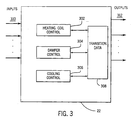
- an air handling unit controller 22 provides control of the supply air temperature using three separate feedback controllers 302, 304 and 306.
- Controller 302 is dedicated to controlling heating coil valve 44
- controller 304 is dedicated to controlling cooling coil valve 46
- controller 306 is dedicated to controlling mixed air plenum 14 (i.e., damper motors 38 - 42 for controlling the positions of dampers 12, 16 and 36, respectively) in accordance with a set of control parameters.
- These control parameters are optimized for the particular control element, e.g., the parameters utilized by controller 302 are optimized for heating coil valve 44 control. At any given time, only one controller is operating.
- controllers 302 - 306 are coupled to and access a memory in which transition data 308 is retained defining the transitions between operating modes, and hence which of the controllers are actively operating.
- Air handling unit controller 22 receives system performance data via inputs 310, and in accordance with transition data 308 defining which controller is operating, provides control outputs 312 for controlling the system operation.
- an alternative preferred embodiment of air handling unit controller 22 sees the use of one controller 402 with three sets of controller parameters 404 - 408 corresponding to the various modes of operation retained in memory 410.
- Memory 410 also includes transition data 412 for defining transitions between operating modes, and hence which set of controller parameters are executed by controller 402.
- Controller 22 receives system performance data via inputs 414, and in accordance with the transition data 412 defining which controller is operating, provides control outputs, 316 for controlling the system operation.
- Fig. 5 shows a state transition diagram illustrating transition data 308/412 and the controller parameters associated with the operating modes, respectively, in accordance with either preferred implementation. The states shown in Fig. 5 are described below.
- the changeover temperature could equal the return air temperature
- the deadband could equal O.56°C .
- the purpose of the deadband temperature is to prevent cycling from State 3 to State 4 due to noise in the return and/or outdoor air temperature sensors, 24 and 28 respectively, readings.
- State 4 also uses feedback control to modulate the flow of cold water to the cooling coil 32 via valve 46, thereby controlling the amount of energy extracted from the air.
- the outdoor air damper 12 is set at the minimum outdoor air position.
- Economizer logic is used to determine the transition to State 3. In the state diagram shown in Figure 3, transition to State 3 occurs when the outdoor air temperature is less than the changeover temperature minus the deadband temperature.
- each of controllers 302 - 306 can be independently tuned for each control loop. Another advantage is that it could be used with a distributed control system. The current trend is towards using intelligent sensors and actuators that contain microprocessors.
- VAV 600 is designed to maintain a constant supply air temperature setpoint and deliver a variable amount of air into a controlled area of a building to maintain the area at a desired temperature.
- VAV 600 is preferably an electro-mechanical device with a digital controller 620. It is shown for a single duct application with a series fan arrangement. It will be appreciated that the invention has application to other implementations of VAV unit 600. Having distributed digital control, VAV 600 may operate in a standalone manner, or may be coupled to a global control system through a network arrangement such as the Metasys Network (registered trademark) system available from Johnson Controls, Inc. of Milwaukee, Wisconsin.
- Metasys Network registered trademark
- VAV 600 When coupled to a network, VAV 600 communicates using standard objects which reside within the VAV controller 620. In this manner, controller 620 may retain "point" information which may be retrieve and viewed by a user at any user interface on the network.
- VAV 600 communicates through two ports 642 and 644, one for an N2 bus connection and one for an N3 bus, respectively.
- VAV 600 is configurable through global tools with applications developed based upon standard objects, assembly objects and nested applications such provided in the Metasys Application Basic Programming Language available from Johnson Controls, Inc. Once the application is created using the global tools, it may be downloaded to VAV 600 using an appropriate protocol such as BACnet.
- VAV 600 series fan 612 is, as observed, installed in series with the supply air stream.
- Variable air volume cold air is supplied into the fan chamber 618 from inlet duct 602 which is coupled to the air distribution system for the building for receiving supply air at the supply air temperature.
- Air flow sensor 604 provides supply air flow information, and damper 606 and damper actuator 608 act as a throttle for controlling the flow of supply air into VAV 600. For example, if cooling is not required, damper 606 may be adjusted to its minimum flow setting. Additional air is drawn from the plenum duct 610 which is coupled to receive air from the zone to maintain a relatively constant flow of air into the zone.
- Fan flow sensor 612 provides zone air flow information, and flow adjust damper 614 allows for control of the zone flow. Finally, should heat be required, heat coil box 616 may be activated to warm the air in fan chamber 618 and supplemental heat coil 617 may be activated for warming air as it flows into the zone.
- VAV controller 620 is implemented in accordance with the present invention as described above and includes a plurality of control elements 622 - 628 associated with each of the system elements.
- VAV controller 620 includes box heating controller 622, supplemental heating controller 624, cooling controller 626 and flow controller 628. Though each of these controllers is shown associated with controller 620, it should be understood that each may be implemented in a distributed fashion. That is, the specific controller may be associated with the system element itself.
- box heating controller 622 may be implemented with box heating coil 616 without departing from the fair scope of the invention.
- VAV controller 620 contains the transition data 630, preferably retained in memory within VAV controller 620, implementing the state transition logic illustrated in Figs. 7a and 7b thereby determining the mode of operation based upon the current mode of operation, system performance data (i.e., flow rates and zone temperatures) and setpoints all shown generally as inputs 632.
- Control elements 622 - 628 may implement any suitable control strategy, and preferably, implement a control strategy optimized to the system element being controlled.
- box heat controller 622, supplemental heat controller 624 and cooling controller each implement a proportional-integral-derivative feedback controller using the predictive adaptive control technology disclosed in the aforementioned commonly assigned United States Patents and United States Patent Application.
- FIG. 7a illustrates the available modes of system operation and the transitions therebetween.
- Fig. 7b illustrates the operating states associated with the automatic operation mode and the transitions therebetween.
- a mode is selected by the system user, using a network interface or interfacing directly with controller 620, setting the "HVAC Mode Request" equal to the selected mode.
- This is illustrated in Fig. 7a as a link, generally shown as 714, leading into a mode having the HVAC Mode Request set equal to the particular mode and a link, generally shown as 716, exiting a mode having the HVAC Mode Request set not equal to the particular mode.
- the following is a description of the possible modes:
- Auto mode 700 the controller runs automatically to meet the control objectives.
- Auto mode multiple states.
- the user requests Auto mode for the VAV controller 620 and the process dynamics determine the current Auto state.
- the current Auto state is Auto No Action Required when the zone temperature is greater than the heating zone temperature setpoint and the zone temperature is less than the cooling zone temperature setpoint.
- Fig. 7b Each Auto state and the transitions between these states are shown in Fig. 7b.
- shutdown box open 702 Two shutdown options will be available: shutdown box open 702 and shutdown box closed 704.
- the damper actuator at the shutdown box open mode 702 will control flow rate to satisfy the occupied cooling maximum flow rate setpoint.
- the damper actuator At the shutdown box closed mode 704, the damper actuator will be driven to the full closed end stop.
- all the devices that are associated with the outputs of the controller (fan, supplemental heat, box heat, and lighting) are turned off.
- Window mode 706 is similar to shutdown closed except it is dependent on a low limit temperature setpoint that will allow supplemental heat to operate. Upon the recognition of this mode, the damper is closed, fans are switched off and the supplemental heat is controlled to maintain the low limit temperature setpoint. In window mode 706, only the room temperature is monitored, the box heating is disabled, and supplemental heating is enabled if the temperature falls below the low limit setpoint.
- the HVAC Mode Control can also be forced to window mode 706 by a supervisory requested command.
- warmup mode 708 known as the central system warmup, the air handling unit provides warm air through the supply duct as needed to bring the system to normal occupied operating conditions.
- warmup the VAV flow setpoint action is reversed.
- supplemental heat is always enabled, and the box heat and parallel fans are disabled by default.
- Water flush mode 710 is typically used during the startup and commissioning of VAV controllers on a new jobsite for the flushing, balancing, or maintenance of building heating water systems. Incremental, proportional, and two position-normally open and normally closed-heating outputs are affected by this feature.
- Autocalibration mode 712 will be performed every operator defined period within an application object.
- a counter when expired, is used to initiate autocalibration.
- Autocalibration will turn the parallel or series box fan (if present) off.
- Autocalibration would drive the damper actuator closed for auto zero time, and calibrate the analog input flow sensor value based on zero flow.
- the autocalibration for each controller will be sequentially staggered so several controllers will not autocalibrate at the same time.
- FIG. 7b the operating states of VAV unit 600 from the Auto mode 700 are shown. From the Auto mode 700 where no action is required, and with the HVAC Mode Request set equal to auto, VAV controller 620 will function without user intervention to meet the system performance criteria (user set points, energy consumption demands, flow requirements, etc.).
- a transition from a state, such as no action 700 to auto cooling 720 occurs when the transition conditions defined by the transition data and illustrated on the links joining the states, for example link 722, are met.
- Once a state is entered for example once the system has entered auto cool 720, it will remain in that state until the transition conditions for exiting the state, for example as shown on link 724, are met.
- the operating states of VAV 600 include, in addition to no action 700 and auto cool 720, auto box heat 726, auto supplemental heating with full box heating 728, auto supplemental heating 730 and auto box heating with full supplemental heating 732.
- the operation of the system can be easily reconfigured. For example, should the user prefer box heating prior to supplemental heating by defining transition data 630 appropriately box heating 726 can be entered before supplemental heating 730, see for example link 734.
- the concept of the state diagram also assists the user in viewing operation of the system.
- a series of user interface displays are shown.
- the controller is part of networked environmental control system including user interfaces having screen display.
- the user by selecting the appropriate option, can retrieve the display shown in Fig. 8 showing current system mode of operation.
- the main portion of the window is a state transition diagram 800.
- State transition diagram 800 is representative of a system including mechanical as well as ice storage cooling sources.
- FIG. 8 shows the controller in the Demand Limiting state 802.
- the controller uses both the chiller and ice storage to stay below a preset electric demand limit without depleting the ice storage prematurely.
- the various conditions indicated in field 818 may change, the status of the conditions being indicated by the check boxes 820. This in turn may cause the mode of operation to change.
- a change of state is indicated in the window by a thick arrow 822 going from the previous mode of operation to the current mode of operation.
- Fig. 8 illustrates that when it was predicted that energy usage was "Approaching Demand Target", the corresponding box became checked, and the controller switched from the Chiller Priority mode 806 to the Demand Limiting mode 802.
- a description 830 of the current mode of operation and why this mode was chosen 832 can be obtained by using an input device and selecting anywhere in the state transition diagram screen 800. Upon making the selection, a State Transition Description window, Fig. 9, displays the requested information.
- the caption underneath the scroll bar indicates what state (current or past) is displayed, for example, Fig. 10.
- the date and time information 826 at the bottom right of the window tells when the transition between the modes occurred.
- Field 818 with the check boxes 820 illustrates the conditions of the various critical flags that determine the mode of operation.
- the bar graph 828 to the right of the screen can show the status of a system element, for example a percent utilization, and in this example, shows the ice inventory at the time the change occurred. Likewise, selecting anywhere in this screen will retrieve a State Transition Description window, as shown in Fig. 9, for this previous state.
- a Sys Var button 834 is provided and allows the user to retrieve and view the system variables, Fig. 11. If the current state is being displayed, the current system variables are displayed. Selecting the plot button 836, provides a plot of the system variables versus time or by transition as requested by the user. If a past state is being displayed, selecting the Sys Var button 834 displays the system variables values at that transition.
Landscapes
- Engineering & Computer Science (AREA)
- Chemical & Material Sciences (AREA)
- Combustion & Propulsion (AREA)
- Mechanical Engineering (AREA)
- General Engineering & Computer Science (AREA)
- Physics & Mathematics (AREA)
- General Physics & Mathematics (AREA)
- Automation & Control Theory (AREA)
- Air Conditioning Control Device (AREA)
Description
- This invention relates generally to environmental control systems for heating, ventilating and air conditioning (HVAC) applications and more particularly, to a system and method of controlling elements of an environmental control system.
- Environmental control systems such as heating, ventilating and air conditioning (HVAC) systems are well known and are designed and implemented to maintain environmental conditions within buildings. A typical installation sees the building divided into zones, and the HVAC system is adapted to maintain each of the zones within predefined environmental parameters (e.g., temperature, humidity, outdoor-recirculated air ratio, etc.). In this exemplary installation, an air distribution system connects each of the zones with an air handling unit (AHU) for providing a supply of conditioned air to the zones.
- The AHU generally includes elements for introducing outdoor air into the system and for exhausting air from the system; elements for heating, cooling, filtering and otherwise conditioning the air in the system; and elements for circulating the air within the air distribution system at a desired flow rate. The AHU also includes a controller to control the operation of these elements. A primary task of the AHU is to provide supply air to each of the particular zones to offset the thermal loads imposed on the zone to maintain a comfortable environment for the occupants. Because thermal loads for the zones can vary markedly, it is common for an AHU to be controlled to maintain the supply air temperature at a setpoint value that is sufficiently low to satisfy the zone with the largest load at any given time. If needed, the air stream is throttled and/or reheated at terminal boxes to provide adequate comfort in all zones.
- AHU controllers commonly use sequencing logic to determine the most economic way to utilize the elements of the AHU to minimize the cost of maintaining the supply air temperature at the setpoint value. For instance, it is not uncommon for a building subjected to large daily temperature swings to require mechanical heating in the morning and mechanical cooling in the afternoon. Costs associated with mechanical cooling can be reduced using economizer cycle control. Economizer cycle control involves modulating dampers located in the mixing box to control the amount of outdoor air that is introduced to the AHU. Under the proper outdoor air conditions and economizer cycle control, the supply air temperature can be maintained at the setpoint value without the use (or with reduced use) of mechanical cooling.
- Economizer cycle control logic typically involves a comparison of the outdoor and return air temperatures or enthalpies. If the outdoor air temperature is greater than some minimum value and less than the return air temperature, an opportunity exists to reduce mechanical cooling costs.
- US 4,501,125 in the name of The Trane Company discloses a temperature conditioning system in which staging control actions are stored in a solid state memory, accessed by a microprocessor. DE 4031050 in the name of Uher AG also deals with a climate system including two separate controllers.
- On the surface, sequencing logic and economiser control are quite intuitive. In practice, however, the logic can be very difficult to follow and just as challenging to implement because of numerous exceptional cases (e.g. freeze control etc) that must be addressed. This was especially true with pneumatic control systems. It has been demonstrated for pneumatic control systems of actual AHUs that the outdoor air damper and heating coil valve may cycle between fully open and fully closed approximately every two minutes. This wastes energy and leads to excessive component wear. The advent of digital control has done little to improve the situation because, rather than taking full advantage of the programming capabilities of digital controllers, logic used in pneumatic controllers has simply been adapted to the digital controllers.
- A first aspect of the invention consists in an environmental control system having a plurality of devices for altering a condition of an environment inside a building, the control system comprising:
- a plurality of controllers each being operatively coupled to control a different one of the plurality of the devices and implementing one of a plurality of system feedback control loops, which respond to performance of the environmental control; and
- a unit controller having a plurality of control states (Figure 5) and responding to sets of transition data by determining which one of the plurality of control states is active at any given point in time, wherein the one of the plurality of control states that is active determines which of the plurality of controllers is active at that given point in time, the control system further comprises a display device coupled to receive data regarding operation of the unit controller, the display device being operable for representing each of the plurality of control states by a respective display element and each of the sets of transition data as a display link joining respective ones of the control states.
-
- The present invention provides a sequencing control strategy for environmental system controllers that takes better advantage of the capabilities of the system elements to enhance performance and reduce operating costs. Digital controller technology is included and operates in accordance with a state transition diagram clarifying conditions that must exist for the environmental controller to switch from one mode of operation to another (e.g. from a cooling mode with dampers set at the minimum position to a cooling mode with the dampers modulating to reduce the energy used for mechanical cooling). Several controllers sequentially operate in accordance with transition data (the state transition diagram) and in response to system performance characteristics for controlling system operation.
- In a preferred embodiment of the present invention, the environmental control system includes several controllers each optimised for controlling an associated one of the environmental system elements. In accordance with state transition logic retained in memory and accessed by the controllers, system control is passed between the controllers depending on the required operating mode in view of measured system performance data.
- In an alternate preferred embodiment of the present invention, the plurality of controllers is constituted by a single controller adapted to access one of several sets of control parameters each of which is optimized for controlling an associated one of the environmental control system elements. In accordance with state transition logic, the controller operates a preferred set of control parameters depending on the required operating mode in view of measured system performance data.
- In still an additional preferred embodiment of the present invention a user interface including a representation of the state transition logic enhances system operation. The interface allows simplified viewing of system operation and faults. In addition, the interface provides a vehicle for simplified system modification.
- These and other advantages and features of the present invention will be readily appreciated by one of ordinary skill in the art from the following detailed description of the preferred embodiments, the subjoined claims and the attached figures.
-
- Fig. 1 is a schematic diagram of an air handling unit (AHU);
- Fig. 2 is a block diagram illustrating a prior art AHU controller;
- Fig. 3 is a block diagram illustrating an AHU controller in accordance with a preferred embodiment of the present invention;
- Fig. 4 is a block diagram illustrating an AHU controller in accordance with an alternate preferred embodiment of the present invention;
- Fig. 5 is a diagram illustrating the state transition data in accordance with a preferred embodiment of the present invention;
- Fig. 6 is a block diagram illustrating a variable-air-volume (VAV) device adapted in accordance with the present invention;
- Fig. 7a is a diagram illustrating state transition data in accordance with a preferred embodiment of the present invention for use with the VAV device of Fig. 6;
- Fig. 7b is a diagram illustrating state transition data in accordance with a preferred embodiment of the present invention for use with the VAV device of Fig. 6;
- Fig. 8 is a representation of a graphic user interface in accordance with a preferred embodiment of the present invention;
- Fig. 9 is a further representation of a graphic user interface in accordance with a preferred embodiment of the present invention;
- Fig. 10 is a further representation of a graphic user interface in accordance with a preferred embodiment of the present invention; and
- Fig. 11 is a further representation of a graphic user interface in accordance with a preferred embodiment of the present invention.
-
- The present invention will be described in terms of several preferred embodiments. It should be understood from the outset that the present invention has a wide range of applications extending far beyond the examples described herein. Referring then to Fig. 1 the components of the schematically illustrated AHU 10 used to maintain the supply air temperature at the setpoint value are shown. This is done for simplicity and should in no way imply that the invention is limited to these elements.
- Air enters AHU 10 through the
outdoor air damper 12 and, depending on themixing box 14 damper settings (controlling the positions ofoutdoor air damper 12,exhaust air damper 36 andrecirculation damper 16 via actuation ofdamper motors recirculation air damper 16. Air within AHU 10 is circulated bysupply fan 18 and returnfan 20, respectively. The temperatures and flow rates of the outdoor and recirculation air streams will determine the conditions of the supply air exitingmixing box 14. The return air temperature/humidity and flow are measured by temperature/humidity sensor 24 andflow sensor 26. The outdoor air temperature/humidity is measured by temperature/humidity sensor 28. The air exitingmixed air plenum 14 passes throughheating coil 30 and coolingcoil 32. At most only one of the two coils will be active at any given time assuming the sequencing control strategy is implemented properly and there are no valve leaks or other faults in the system. After being conditioned, the air is distributed to the zones through thesupply air ductwork 34. The supply air temperature is measured downstream of thesupply fan 18 by temperature/humidity sensor 25. Return air is drawn from the zones by thereturn fan 20 and is either exhausted or recirculated, depending once again on the position of themixing box 14 dampers. - The air
handling unit controller 22 includes a controller (or controllers) to control theheating coil valve 44, the coolingcoil valve 46, and the damper motors 38 - 42, and control logic to determine the component(s) (heating coil, cooling coil, dampers, cooling coil and dampers) to use to maintain the supply air temperature at the setpoint value at any given time. - Figure 2 shows a flow chart for a prior art
sequencing control strategy 200 which may be implemented in the airhandling unit controller 22 shown in Figure 1.Control strategy 200 is based on strategies used in pneumatic control systems. Asingle feedback controller 202, usually a proportional-integral (PI) controller, is used with this strategy, in conjunction witheconomizer logic 204 and lowselect logic 206, to reduce component costs. The controller output is determined by comparing the supply air temperature to a setpoint. If the scaled output fromfeedback controller 202 is between 100 % and 200 %, mechanical cooling via coolingcoil 32 is used to cool the air. Here 100 % represents no mechanical cooling and 200 % represents maximum mechanical cooling. If the outdoor air conditions are suitable, an economizer cycle 204 (outdoor air dampers fully open) is used simultaneously to reduce the mechanical cooling load. If the output fromfeedback controller 202 is between - 100 % and 0 %,heating coil 30 is used to heat the supply air and the outdoor air damper is at its minimum position determined by ventilation criteria. If the output from the feedback controller is between 0 % and 100 %, outdoor air and return air are mixed inmixed air plenum 14 to produce supply air at the setpoint temperature. This is referred to as free cooling because neither mechanical heating or cooling is used. - The dynamic characteristics of the three processes (i.e., heating, cooling, and free cooling) are significantly different, in which case the use of a single feedback controller is limiting. To maintain stable control, the controller must to be tuned for the worst case conditions. If this is the case, the closed loop response for other conditions will tend to be sluggish. If the feedback controller is not tuned for the worst case conditions, then
valves dampers - The control performance can be improved by using an adaptive controller such as disclosed and described in commonly assigned United States Patent Nos. 5,355,305, 5,506,768 and 5,568,377, to adjust the proportional gain and integral time of
controller 202. However, the parameters may need significant adjustment as the control component changes, that is, as the control changes from cooling to heating. Also, it may be difficult to tune at the transition region because the combined process may be very nonlinear. During the time period that the adaptive controller is adjusting parameters at the transition region, the control performance may be sacrificed. - With reference to Fig. 3, in accordance with a preferred embodiment of the present invention, an air
handling unit controller 22 provides control of the supply air temperature using threeseparate feedback controllers Controller 302 is dedicated to controllingheating coil valve 44,controller 304 is dedicated to controllingcooling coil valve 46, andcontroller 306 is dedicated to controlling mixed air plenum 14 (i.e., damper motors 38 - 42 for controlling the positions ofdampers controller 302 are optimized forheating coil valve 44 control. At any given time, only one controller is operating. Each of controllers 302 - 306 are coupled to and access a memory in which transitiondata 308 is retained defining the transitions between operating modes, and hence which of the controllers are actively operating. Airhandling unit controller 22 receives system performance data viainputs 310, and in accordance withtransition data 308 defining which controller is operating, providescontrol outputs 312 for controlling the system operation. - With reference to Fig. 4, an alternative preferred embodiment of air
handling unit controller 22 sees the use of onecontroller 402 with three sets of controller parameters 404 - 408 corresponding to the various modes of operation retained inmemory 410.Memory 410 also includestransition data 412 for defining transitions between operating modes, and hence which set of controller parameters are executed bycontroller 402.Controller 22 receives system performance data viainputs 414, and in accordance with thetransition data 412 defining which controller is operating, provides control outputs, 316 for controlling the system operation. - Fig. 5 shows a state transition diagram illustrating
transition data 308/412 and the controller parameters associated with the operating modes, respectively, in accordance with either preferred implementation. The states shown in Fig. 5 are described below. - In State I, feedback control is used to modulate the flow of hot water to the
heating coil 30 viavalve 44, thereby controlling the amount of energy transferred to the air. Meanwhile, the mixing box dampers (12, 16 and 36) are positioned for the minimum outdoor air required for ventilation and the coolingcoil valve 46 is closed. The transition toState 2 occurs after the control signal has been saturated at the no heating position for a time period equal to the state transition delay. For all state transitions, the current state must be continuously saturated at either its minimum or maximum limit for a period of time equal to the state transition delay before operation can switch to a new state. - In
State 2, feedback control is used to adjust the position ofdampers dampers State 2, the heating andcooling coil valves State 1 occurs after the control signal for the dampers has been at the minimum outdoor air position for a time period equal to the state transition delay. Transition toState 3 occurs after the control signal for the dampers has been at the maximum outdoor air position for a time period equal to the state transition delay. - In
State 3, feedback control is used to modulate the flow of cold water to the coolingcoil 32 viavalve 46, thereby controlling the amount of energy extracted from the air. Theoutdoor air damper 12 is set at completely open and theheating coil valve 44 is closed. Transition toState 2 occurs after the control signal for mechanical cooling has been saturated at the no cooling position for a time period equal to the state transition delay. Economizer logic is used to determine the transition toState 4. Either an enthalpy based or temperature based economizer logic can be used. In the state diagram shown in Figure 3, logic based on outdoor air temperature is used to determine the transition point. Transition toState 4 occurs when the outdoor air temperature is greater than the changeover temperature plus the deadband temperature. As an example, the changeover temperature could equal the return air temperature, and the deadband could equal O.56°C. The purpose of the deadband temperature is to prevent cycling fromState 3 toState 4 due to noise in the return and/or outdoor air temperature sensors, 24 and 28 respectively, readings. -
State 4 also uses feedback control to modulate the flow of cold water to the coolingcoil 32 viavalve 46, thereby controlling the amount of energy extracted from the air. However, in this case, theoutdoor air damper 12 is set at the minimum outdoor air position. Economizer logic is used to determine the transition toState 3. In the state diagram shown in Figure 3, transition toState 3 occurs when the outdoor air temperature is less than the changeover temperature minus the deadband temperature. - One of the main benefits of the present invention is that each of controllers 302 - 306 can be independently tuned for each control loop. Another advantage is that it could be used with a distributed control system. The current trend is towards using intelligent sensors and actuators that contain microprocessors.
- For example, as shown in Fig. 6 a variable-air-volume (VAV)
unit 600 is designed to maintain a constant supply air temperature setpoint and deliver a variable amount of air into a controlled area of a building to maintain the area at a desired temperature.VAV 600 is preferably an electro-mechanical device with adigital controller 620. It is shown for a single duct application with a series fan arrangement. It will be appreciated that the invention has application to other implementations ofVAV unit 600. Having distributed digital control,VAV 600 may operate in a standalone manner, or may be coupled to a global control system through a network arrangement such as the Metasys Network (registered trademark) system available from Johnson Controls, Inc. of Milwaukee, Wisconsin. When coupled to a network,VAV 600 communicates using standard objects which reside within theVAV controller 620. In this manner,controller 620 may retain "point" information which may be retrieve and viewed by a user at any user interface on the network. PreferablyVAV 600 communicates through twoports VAV 600 is configurable through global tools with applications developed based upon standard objects, assembly objects and nested applications such provided in the Metasys Application Basic Programming Language available from Johnson Controls, Inc. Once the application is created using the global tools, it may be downloaded toVAV 600 using an appropriate protocol such as BACnet. - With reference to Fig. 6,
VAV 600series fan 612 is, as observed, installed in series with the supply air stream. Variable air volume cold air is supplied into thefan chamber 618 frominlet duct 602 which is coupled to the air distribution system for the building for receiving supply air at the supply air temperature.Air flow sensor 604 provides supply air flow information, anddamper 606 anddamper actuator 608 act as a throttle for controlling the flow of supply air intoVAV 600. For example, if cooling is not required,damper 606 may be adjusted to its minimum flow setting. Additional air is drawn from theplenum duct 610 which is coupled to receive air from the zone to maintain a relatively constant flow of air into the zone.Fan flow sensor 612 provides zone air flow information, and flow adjustdamper 614 allows for control of the zone flow. Finally, should heat be required,heat coil box 616 may be activated to warm the air infan chamber 618 andsupplemental heat coil 617 may be activated for warming air as it flows into the zone. - With continued reference to Fig. 6,
VAV controller 620 is implemented in accordance with the present invention as described above and includes a plurality of control elements 622 - 628 associated with each of the system elements.VAV controller 620 includesbox heating controller 622,supplemental heating controller 624, coolingcontroller 626 and flowcontroller 628. Though each of these controllers is shown associated withcontroller 620, it should be understood that each may be implemented in a distributed fashion. That is, the specific controller may be associated with the system element itself. For example,box heating controller 622 may be implemented withbox heating coil 616 without departing from the fair scope of the invention. As described, these control elements may be implemented as discrete controllers or may be implemented as a single controller acting on a number of sets of control parameters with a set being associated with each of the system elements. In addition,VAV controller 620 contains thetransition data 630, preferably retained in memory withinVAV controller 620, implementing the state transition logic illustrated in Figs. 7a and 7b thereby determining the mode of operation based upon the current mode of operation, system performance data (i.e., flow rates and zone temperatures) and setpoints all shown generally asinputs 632. - Control elements 622 - 628 may implement any suitable control strategy, and preferably, implement a control strategy optimized to the system element being controlled. In the preferred embodiment,
box heat controller 622,supplemental heat controller 624 and cooling controller each implement a proportional-integral-derivative feedback controller using the predictive adaptive control technology disclosed in the aforementioned commonly assigned United States Patents and United States Patent Application. - Referring then to Figs. 7a and 7b, illustrated is a nested control architecture in accordance with the preferred embodiments of the present invention. Figure 7a illustrates the available modes of system operation and the transitions therebetween. Fig. 7b illustrates the operating states associated with the automatic operation mode and the transitions therebetween. A mode is selected by the system user, using a network interface or interfacing directly with
controller 620, setting the "HVAC Mode Request" equal to the selected mode. This is illustrated in Fig. 7a as a link, generally shown as 714, leading into a mode having the HVAC Mode Request set equal to the particular mode and a link, generally shown as 716, exiting a mode having the HVAC Mode Request set not equal to the particular mode. The following is a description of the possible modes: - In
Auto mode 700, the controller runs automatically to meet the control objectives. Within Auto mode are multiple states. The user requests Auto mode for theVAV controller 620 and the process dynamics determine the current Auto state. For example, the current Auto state is Auto No Action Required when the zone temperature is greater than the heating zone temperature setpoint and the zone temperature is less than the cooling zone temperature setpoint. Each Auto state and the transitions between these states are shown in Fig. 7b. - Two shutdown options will be available: shutdown box open 702 and shutdown box closed 704. The damper actuator at the shutdown box
open mode 702 will control flow rate to satisfy the occupied cooling maximum flow rate setpoint. At the shutdown box closedmode 704, the damper actuator will be driven to the full closed end stop. When either shutdown is enabled, all the devices that are associated with the outputs of the controller (fan, supplemental heat, box heat, and lighting) are turned off. - As a window is opened, a binary input signifies the open state of the window, the HVAC Mode Control is forced to the
window mode 706. The window open status has the highest priority.Window mode 706 is similar to shutdown closed except it is dependent on a low limit temperature setpoint that will allow supplemental heat to operate. Upon the recognition of this mode, the damper is closed, fans are switched off and the supplemental heat is controlled to maintain the low limit temperature setpoint. Inwindow mode 706, only the room temperature is monitored, the box heating is disabled, and supplemental heating is enabled if the temperature falls below the low limit setpoint. The HVAC Mode Control can also be forced towindow mode 706 by a supervisory requested command. - In
warmup mode 708, known as the central system warmup, the air handling unit provides warm air through the supply duct as needed to bring the system to normal occupied operating conditions. In warmup, the VAV flow setpoint action is reversed. During warmup, supplemental heat is always enabled, and the box heat and parallel fans are disabled by default. - Water
flush mode 710 is typically used during the startup and commissioning of VAV controllers on a new jobsite for the flushing, balancing, or maintenance of building heating water systems. Incremental, proportional, and two position-normally open and normally closed-heating outputs are affected by this feature. -
Autocalibration mode 712 will be performed every operator defined period within an application object. A counter, when expired, is used to initiate autocalibration. Autocalibration will turn the parallel or series box fan (if present) off. Autocalibration would drive the damper actuator closed for auto zero time, and calibrate the analog input flow sensor value based on zero flow. The autocalibration for each controller will be sequentially staggered so several controllers will not autocalibrate at the same time. - With reference now to Fig. 7b, the operating states of
VAV unit 600 from theAuto mode 700 are shown. From theAuto mode 700 where no action is required, and with the HVAC Mode Request set equal to auto,VAV controller 620 will function without user intervention to meet the system performance criteria (user set points, energy consumption demands, flow requirements, etc.). A transition from a state, such as noaction 700 toauto cooling 720, occurs when the transition conditions defined by the transition data and illustrated on the links joining the states, forexample link 722, are met. Once a state is entered, for example once the system has enteredauto cool 720, it will remain in that state until the transition conditions for exiting the state, for example as shown onlink 724, are met. The operating states ofVAV 600 include, in addition to noaction 700 andauto cool 720,auto box heat 726, auto supplemental heating withfull box heating 728, autosupplemental heating 730 and auto box heating with fullsupplemental heating 732. One can see that the operation of the system can be easily reconfigured. For example, should the user prefer box heating prior to supplemental heating by definingtransition data 630 appropriatelybox heating 726 can be entered beforesupplemental heating 730, see forexample link 734. The concept of the state diagram also assists the user in viewing operation of the system. - With reference to Figs. 8 - 11, a series of user interface displays are shown. According to the present invention the controller is part of networked environmental control system including user interfaces having screen display. The user, by selecting the appropriate option, can retrieve the display shown in Fig. 8 showing current system mode of operation. Referring then to Fig. 8, the main portion of the window is a state transition diagram 800. State transition diagram 800 is representative of a system including mechanical as well as ice storage cooling sources. There are 8 basic modes of operation (or states) 802 - 816 that are represented as circles. Transitions between states are represented by the arrows, generally 815, connecting the circles 802 - 816. In each state unique actions are being taken to control the system as has been described. For example, Fig. 8 shows the controller in the
Demand Limiting state 802. In this mode the controller uses both the chiller and ice storage to stay below a preset electric demand limit without depleting the ice storage prematurely. As the day progresses the various conditions indicated infield 818 may change, the status of the conditions being indicated by thecheck boxes 820. This in turn may cause the mode of operation to change. A change of state is indicated in the window by athick arrow 822 going from the previous mode of operation to the current mode of operation. For example, Fig. 8 illustrates that when it was predicted that energy usage was "Approaching Demand Target", the corresponding box became checked, and the controller switched from theChiller Priority mode 806 to theDemand Limiting mode 802. - A
description 830 of the current mode of operation and why this mode was chosen 832 can be obtained by using an input device and selecting anywhere in the statetransition diagram screen 800. Upon making the selection, a State Transition Description window, Fig. 9, displays the requested information. - One can view the previous modes of operation by moving the
scroll bar 824 at the top right of the window. The caption underneath the scroll bar indicates what state (current or past) is displayed, for example, Fig. 10. The date andtime information 826 at the bottom right of the window tells when the transition between the modes occurred.Field 818 with thecheck boxes 820 illustrates the conditions of the various critical flags that determine the mode of operation. Thebar graph 828 to the right of the screen can show the status of a system element, for example a percent utilization, and in this example, shows the ice inventory at the time the change occurred. Likewise, selecting anywhere in this screen will retrieve a State Transition Description window, as shown in Fig. 9, for this previous state. - A
Sys Var button 834 is provided and allows the user to retrieve and view the system variables, Fig. 11. If the current state is being displayed, the current system variables are displayed. Selecting theplot button 836, provides a plot of the system variables versus time or by transition as requested by the user. If a past state is being displayed, selecting theSys Var button 834 displays the system variables values at that transition. - The present invention has been described in terms of preferred embodiments. Its scope is set forth in the attached claims.
Claims (7)
- An environmental control system (10) having a plurality of devices (12, 16, 18, 30, 32, 36) for altering a condition of an environment inside a building, the control system (10) comprising:a plurality of controllers (302, 304, 306) each being operatively coupled to control a different one of the plurality of the devices (12, 16, 18, 30, 32, 36) and implementing one of a plurality of system feedback control loops, which respond to performance of the environmental control; anda unit controller (22) having a plurality of control states and responding to sets of transition data by determining which one of the plurality of control states is active at any given point in time, wherein the one of the plurality of control states that is active determines which of the plurality of controllers (302, 304, 306) is active at that given point in time, characterised in that the control system (10) further comprises a display device (800) coupled to receive data regarding operation of the unit controller (22), the display device being operable for representing each of the plurality of control states by a respective display element (726, 730, 720) and each of the sets of transition data as a display link (722, 724) joining respective ones of the control states.
- The control system (10) as recited in claim 1 wherein at least one of the plurality of controllers (302, 304, 306) implements a proportional-integral feedback control loop on a proportional-integral-derivative feedback control loop.
- The control system (10) as recited in claim 1 further comprising a memory (410) for storing parameters for the plurality of feedback control loops; and the plurality of controllers (302, 304, 306) operate in response to the control parameters read from the memory.
- The control system (10) as recited in claim 3 wherein the memory (410) also stores the state transition data (412).
- The control system (10) as recited in claim 1 wherein the plurality of controllers includes one or more of a controller (302) to operate a heating coil (30), a controller (306) to operate a cooling coil (32), a controller (304) to operate a damper (12), a controller (624) to operate a supplemental heating device and a controller to operate a fan (18).
- The control system (10) of any preceding claim wherein the display device (800) comprises a user input device (310, 414) for allowing a user to respectively select a display link and wherein the display device is operable to display an associated set of transition data.
- The control system (10) of claim 6 wherein the user input device (310, 414) allows a user to respectively select a given display element and is operable to display data related to the feedback control loop associated with that given display element.
Applications Claiming Priority (2)
| Application Number | Priority Date | Filing Date | Title |
|---|---|---|---|
| US08/892,177 US6006142A (en) | 1997-07-14 | 1997-07-14 | Environmental control system and method |
| US892177 | 1997-07-14 |
Publications (2)
| Publication Number | Publication Date |
|---|---|
| EP0892330A1 EP0892330A1 (en) | 1999-01-20 |
| EP0892330B1 true EP0892330B1 (en) | 2002-10-02 |
Family
ID=25399502
Family Applications (1)
| Application Number | Title | Priority Date | Filing Date |
|---|---|---|---|
| EP98305564A Expired - Lifetime EP0892330B1 (en) | 1997-07-14 | 1998-07-13 | Environmental control system and method |
Country Status (4)
| Country | Link |
|---|---|
| US (2) | US6006142A (en) |
| EP (1) | EP0892330B1 (en) |
| JP (1) | JPH11193953A (en) |
| DE (1) | DE69808393T2 (en) |
Cited By (9)
| Publication number | Priority date | Publication date | Assignee | Title |
|---|---|---|---|---|
| US8325637B2 (en) | 2007-07-31 | 2012-12-04 | Johnson Controls Technology Company | Pairing wireless devices of a network using relative gain arrays |
| CN106196461A (en) * | 2016-07-18 | 2016-12-07 | 珠海格力电器股份有限公司 | Control method and device of multi-connected air conditioning unit and multi-connected air conditioning unit |
| WO2017113511A1 (en) * | 2015-12-31 | 2017-07-06 | 中山大洋电机股份有限公司 | Constant air volume control method for an air supply device driven by multiple motors |
| US9702578B2 (en) | 2008-07-11 | 2017-07-11 | Kabushiki Kaisha Toshiba | Air conditioning control system for controlling outside air control and return air control of air conditioning system |
| US9953474B2 (en) | 2016-09-02 | 2018-04-24 | Honeywell International Inc. | Multi-level security mechanism for accessing a panel |
| US10126009B2 (en) | 2014-06-20 | 2018-11-13 | Honeywell International Inc. | HVAC zoning devices, systems, and methods |
| US10789800B1 (en) | 2019-05-24 | 2020-09-29 | Ademco Inc. | Systems and methods for authorizing transmission of commands and signals to an access control device or a control panel device |
| US10832509B1 (en) | 2019-05-24 | 2020-11-10 | Ademco Inc. | Systems and methods of a doorbell device initiating a state change of an access control device and/or a control panel responsive to two-factor authentication |
| US11927352B2 (en) | 2015-03-05 | 2024-03-12 | Honeywell International Inc. | Wireless actuator service |
Families Citing this family (150)
| Publication number | Priority date | Publication date | Assignee | Title |
|---|---|---|---|---|
| US6006142A (en) * | 1997-07-14 | 1999-12-21 | Seem; John E. | Environmental control system and method |
| US6219590B1 (en) * | 1998-04-03 | 2001-04-17 | Johnson Controls Technology Co. | State machine controller for operating variable air volume terminal units of an environmental control system |
| US6366832B2 (en) * | 1998-11-24 | 2002-04-02 | Johnson Controls Technology Company | Computer integrated personal environment system |
| EP1083390A3 (en) * | 1999-09-07 | 2002-12-04 | Sharp Kabushiki Kaisha | Air conditioner having dehumidifying and ventilating functions |
| WO2001083125A1 (en) | 2000-05-01 | 2001-11-08 | Board Of Regents Of University Of Nebraska | Fume hood exhaust stack system |
| US6369716B1 (en) | 2000-12-01 | 2002-04-09 | Johnson Controls Technology Company | System and method for controlling air quality in a room |
| US6609967B2 (en) * | 2000-12-11 | 2003-08-26 | Phoenix Controls Corporation | Methods and apparatus for recirculating air in a controlled ventilated environment |
| US7640512B1 (en) * | 2000-12-22 | 2009-12-29 | Automated Logic Corporation | Updating objects contained within a webpage |
| US6415617B1 (en) | 2001-01-10 | 2002-07-09 | Johnson Controls Technology Company | Model based economizer control of an air handling unit |
| US6778945B2 (en) | 2001-12-12 | 2004-08-17 | Battelle Memorial Institute | Rooftop package unit diagnostician |
| US20030153986A1 (en) * | 2002-02-14 | 2003-08-14 | Johnson Controls Technology Company | Filtered variable control method for activating an electrical device |
| US7024254B2 (en) * | 2002-02-14 | 2006-04-04 | Johnson Controls Technology Company | Method for controlling a discrete system |
| US7505877B2 (en) * | 2002-03-08 | 2009-03-17 | Johnson Controls Technology Company | System and method for characterizing a system |
| JP3783859B2 (en) * | 2002-07-19 | 2006-06-07 | 日立プラント建設株式会社 | Air conditioning equipment and control method thereof |
| DE60310575T2 (en) * | 2002-08-28 | 2007-10-11 | Interdigital Technology Corp., Wilmington | SYSTEM FOR ADMINISTERING WIRELESS RADIO MANAGEMENT USING AN AUTOMATED SYSTEM |
| US7024258B2 (en) * | 2003-03-17 | 2006-04-04 | Siemens Building Technologies, Inc. | System and method for model-based control of a building fluid distribution system |
| US6813895B2 (en) * | 2003-09-05 | 2004-11-09 | Carrier Corporation | Supercritical pressure regulation of vapor compression system by regulation of adaptive control |
| US6879881B1 (en) | 2003-10-17 | 2005-04-12 | Russell G. Attridge, Jr. | Variable air volume system including BTU control function |
| CA2485049A1 (en) * | 2003-10-17 | 2005-04-17 | Russell G. Attridge, Jr. | Thermal balance temperature control system |
| US7272452B2 (en) * | 2004-03-31 | 2007-09-18 | Siemens Vdo Automotive Corporation | Controller with configurable connections between data processing components |
| US7412842B2 (en) | 2004-04-27 | 2008-08-19 | Emerson Climate Technologies, Inc. | Compressor diagnostic and protection system |
| US7275377B2 (en) | 2004-08-11 | 2007-10-02 | Lawrence Kates | Method and apparatus for monitoring refrigerant-cycle systems |
| WO2006023075A2 (en) | 2004-08-11 | 2006-03-02 | Lawrence Kates | Method and apparatus for monitoring refrigerant-cycle systems |
| US7424343B2 (en) * | 2004-08-11 | 2008-09-09 | Lawrence Kates | Method and apparatus for load reduction in an electric power system |
| US8172153B1 (en) | 2004-12-30 | 2012-05-08 | Kennedy Metal Products & Buildings, Inc. | Energy usage control for a building |
| US7434413B2 (en) * | 2005-01-10 | 2008-10-14 | Honeywell International Inc. | Indoor air quality and economizer control methods and controllers |
| US20070022770A1 (en) * | 2005-07-22 | 2007-02-01 | Mingsheng Liu | Building temperature control system and method |
| GB0600274D0 (en) * | 2006-01-09 | 2006-02-15 | Oxycell Holding Bv | Cooling and ventilation device |
| US7891573B2 (en) | 2006-03-03 | 2011-02-22 | Micro Metl Corporation | Methods and apparatuses for controlling air to a building |
| US8590325B2 (en) | 2006-07-19 | 2013-11-26 | Emerson Climate Technologies, Inc. | Protection and diagnostic module for a refrigeration system |
| US20080216494A1 (en) | 2006-09-07 | 2008-09-11 | Pham Hung M | Compressor data module |
| JP5073281B2 (en) * | 2006-12-12 | 2012-11-14 | 株式会社Pfu | Sticky note display processing apparatus and sticky note display processing method |
| US7496472B2 (en) * | 2007-01-25 | 2009-02-24 | Johnson Controls Technology Company | Method and system for assessing performance of control systems |
| US20080179408A1 (en) * | 2007-01-30 | 2008-07-31 | Johnson Controls Technology Company | Sensor-free optimal control of air-side economizer |
| US7827813B2 (en) | 2007-01-30 | 2010-11-09 | Johnson Controls Technology Company | Adaptive real-time optimization control |
| DE102007010268A1 (en) * | 2007-03-02 | 2008-09-04 | Liebherr-Aerospace Lindenberg Gmbh | Mixing device for aircraft air conditioning |
| US20080281439A1 (en) * | 2007-05-09 | 2008-11-13 | Johnson Controls Technology Company | Building automation systems and methods |
| US20080277486A1 (en) * | 2007-05-09 | 2008-11-13 | Johnson Controls Technology Company | HVAC control system and method |
| US20090065596A1 (en) * | 2007-05-09 | 2009-03-12 | Johnson Controls Technology Company | Systems and methods for increasing building space comfort using wireless devices |
| DE112008001836T5 (en) | 2007-07-17 | 2010-06-24 | Johnson Controls Technology Company, Holland | Extreme value control with actuator saturation control |
| DE112008001872B4 (en) | 2007-07-17 | 2016-08-11 | Johnson Controls Technology Company | Extreme value control with reset control |
| US20090037142A1 (en) | 2007-07-30 | 2009-02-05 | Lawrence Kates | Portable method and apparatus for monitoring refrigerant-cycle systems |
| US9140728B2 (en) | 2007-11-02 | 2015-09-22 | Emerson Climate Technologies, Inc. | Compressor sensor module |
| US8326464B2 (en) * | 2008-08-29 | 2012-12-04 | Trane International Inc. | Return fan control system and method |
| US20100070089A1 (en) * | 2008-09-15 | 2010-03-18 | Johnson Controls Technology Company | Hvac controller user interfaces |
| US9261888B2 (en) | 2008-10-27 | 2016-02-16 | Lennox Industries Inc. | System and method of use for a user interface dashboard of a heating, ventilation and air conditioning network |
| US8600558B2 (en) | 2008-10-27 | 2013-12-03 | Lennox Industries Inc. | System recovery in a heating, ventilation and air conditioning network |
| US8655490B2 (en) | 2008-10-27 | 2014-02-18 | Lennox Industries, Inc. | System and method of use for a user interface dashboard of a heating, ventilation and air conditioning network |
| US9432208B2 (en) | 2008-10-27 | 2016-08-30 | Lennox Industries Inc. | Device abstraction system and method for a distributed architecture heating, ventilation and air conditioning system |
| US8564400B2 (en) | 2008-10-27 | 2013-10-22 | Lennox Industries, Inc. | Communication protocol system and method for a distributed-architecture heating, ventilation and air conditioning network |
| US9678486B2 (en) | 2008-10-27 | 2017-06-13 | Lennox Industries Inc. | Device abstraction system and method for a distributed-architecture heating, ventilation and air conditioning system |
| US8892797B2 (en) | 2008-10-27 | 2014-11-18 | Lennox Industries Inc. | Communication protocol system and method for a distributed-architecture heating, ventilation and air conditioning network |
| US8798796B2 (en) | 2008-10-27 | 2014-08-05 | Lennox Industries Inc. | General control techniques in a heating, ventilation and air conditioning network |
| US8352081B2 (en) | 2008-10-27 | 2013-01-08 | Lennox Industries Inc. | Communication protocol system and method for a distributed-architecture heating, ventilation and air conditioning network |
| US8762666B2 (en) | 2008-10-27 | 2014-06-24 | Lennox Industries, Inc. | Backup and restoration of operation control data in a heating, ventilation and air conditioning network |
| US8437878B2 (en) | 2008-10-27 | 2013-05-07 | Lennox Industries Inc. | Alarm and diagnostics system and method for a distributed architecture heating, ventilation and air conditioning network |
| US8352080B2 (en) | 2008-10-27 | 2013-01-08 | Lennox Industries Inc. | Communication protocol system and method for a distributed-architecture heating, ventilation and air conditioning network |
| US9651925B2 (en) | 2008-10-27 | 2017-05-16 | Lennox Industries Inc. | System and method for zoning a distributed-architecture heating, ventilation and air conditioning network |
| US8725298B2 (en) | 2008-10-27 | 2014-05-13 | Lennox Industries, Inc. | Alarm and diagnostics system and method for a distributed architecture heating, ventilation and conditioning network |
| US8855825B2 (en) | 2008-10-27 | 2014-10-07 | Lennox Industries Inc. | Device abstraction system and method for a distributed-architecture heating, ventilation and air conditioning system |
| US8442693B2 (en) | 2008-10-27 | 2013-05-14 | Lennox Industries, Inc. | System and method of use for a user interface dashboard of a heating, ventilation and air conditioning network |
| US9632490B2 (en) | 2008-10-27 | 2017-04-25 | Lennox Industries Inc. | System and method for zoning a distributed architecture heating, ventilation and air conditioning network |
| US8600559B2 (en) | 2008-10-27 | 2013-12-03 | Lennox Industries Inc. | Method of controlling equipment in a heating, ventilation and air conditioning network |
| US9268345B2 (en) | 2008-10-27 | 2016-02-23 | Lennox Industries Inc. | System and method of use for a user interface dashboard of a heating, ventilation and air conditioning network |
| US8452456B2 (en) | 2008-10-27 | 2013-05-28 | Lennox Industries Inc. | System and method of use for a user interface dashboard of a heating, ventilation and air conditioning network |
| US9377768B2 (en) | 2008-10-27 | 2016-06-28 | Lennox Industries Inc. | Memory recovery scheme and data structure in a heating, ventilation and air conditioning network |
| US8543243B2 (en) | 2008-10-27 | 2013-09-24 | Lennox Industries, Inc. | System and method of use for a user interface dashboard of a heating, ventilation and air conditioning network |
| US8744629B2 (en) | 2008-10-27 | 2014-06-03 | Lennox Industries Inc. | System and method of use for a user interface dashboard of a heating, ventilation and air conditioning network |
| US9152155B2 (en) | 2008-10-27 | 2015-10-06 | Lennox Industries Inc. | Device abstraction system and method for a distributed-architecture heating, ventilation and air conditioning system |
| US8615326B2 (en) | 2008-10-27 | 2013-12-24 | Lennox Industries Inc. | System and method of use for a user interface dashboard of a heating, ventilation and air conditioning network |
| US8437877B2 (en) | 2008-10-27 | 2013-05-07 | Lennox Industries Inc. | System recovery in a heating, ventilation and air conditioning network |
| US8560125B2 (en) | 2008-10-27 | 2013-10-15 | Lennox Industries | Communication protocol system and method for a distributed-architecture heating, ventilation and air conditioning network |
| US8977794B2 (en) | 2008-10-27 | 2015-03-10 | Lennox Industries, Inc. | Communication protocol system and method for a distributed-architecture heating, ventilation and air conditioning network |
| US8655491B2 (en) | 2008-10-27 | 2014-02-18 | Lennox Industries Inc. | Alarm and diagnostics system and method for a distributed architecture heating, ventilation and air conditioning network |
| US8255086B2 (en) | 2008-10-27 | 2012-08-28 | Lennox Industries Inc. | System recovery in a heating, ventilation and air conditioning network |
| US8548630B2 (en) | 2008-10-27 | 2013-10-01 | Lennox Industries, Inc. | Alarm and diagnostics system and method for a distributed-architecture heating, ventilation and air conditioning network |
| US9325517B2 (en) | 2008-10-27 | 2016-04-26 | Lennox Industries Inc. | Device abstraction system and method for a distributed-architecture heating, ventilation and air conditioning system |
| US8433446B2 (en) | 2008-10-27 | 2013-04-30 | Lennox Industries, Inc. | Alarm and diagnostics system and method for a distributed-architecture heating, ventilation and air conditioning network |
| US8994539B2 (en) | 2008-10-27 | 2015-03-31 | Lennox Industries, Inc. | Alarm and diagnostics system and method for a distributed-architecture heating, ventilation and air conditioning network |
| US8661165B2 (en) | 2008-10-27 | 2014-02-25 | Lennox Industries, Inc. | Device abstraction system and method for a distributed architecture heating, ventilation and air conditioning system |
| US8694164B2 (en) | 2008-10-27 | 2014-04-08 | Lennox Industries, Inc. | Interactive user guidance interface for a heating, ventilation and air conditioning system |
| US8239066B2 (en) | 2008-10-27 | 2012-08-07 | Lennox Industries Inc. | System and method of use for a user interface dashboard of a heating, ventilation and air conditioning network |
| US8788100B2 (en) | 2008-10-27 | 2014-07-22 | Lennox Industries Inc. | System and method for zoning a distributed-architecture heating, ventilation and air conditioning network |
| US8452906B2 (en) | 2008-10-27 | 2013-05-28 | Lennox Industries, Inc. | Communication protocol system and method for a distributed-architecture heating, ventilation and air conditioning network |
| US8874815B2 (en) | 2008-10-27 | 2014-10-28 | Lennox Industries, Inc. | Communication protocol system and method for a distributed architecture heating, ventilation and air conditioning network |
| US8463443B2 (en) | 2008-10-27 | 2013-06-11 | Lennox Industries, Inc. | Memory recovery scheme and data structure in a heating, ventilation and air conditioning network |
| US8774210B2 (en) | 2008-10-27 | 2014-07-08 | Lennox Industries, Inc. | Communication protocol system and method for a distributed-architecture heating, ventilation and air conditioning network |
| US8295981B2 (en) | 2008-10-27 | 2012-10-23 | Lennox Industries Inc. | Device commissioning in a heating, ventilation and air conditioning network |
| US8802981B2 (en) | 2008-10-27 | 2014-08-12 | Lennox Industries Inc. | Flush wall mount thermostat and in-set mounting plate for a heating, ventilation and air conditioning system |
| US8463442B2 (en) | 2008-10-27 | 2013-06-11 | Lennox Industries, Inc. | Alarm and diagnostics system and method for a distributed architecture heating, ventilation and air conditioning network |
| PL2246634T3 (en) * | 2009-04-27 | 2015-03-31 | Stulz Gmbh | Direct free cooling |
| US8239168B2 (en) * | 2009-06-18 | 2012-08-07 | Johnson Controls Technology Company | Systems and methods for fault detection of air handling units |
| US9196009B2 (en) | 2009-06-22 | 2015-11-24 | Johnson Controls Technology Company | Systems and methods for detecting changes in energy usage in a building |
| US8600556B2 (en) | 2009-06-22 | 2013-12-03 | Johnson Controls Technology Company | Smart building manager |
| US8731724B2 (en) | 2009-06-22 | 2014-05-20 | Johnson Controls Technology Company | Automated fault detection and diagnostics in a building management system |
| US10739741B2 (en) | 2009-06-22 | 2020-08-11 | Johnson Controls Technology Company | Systems and methods for detecting changes in energy usage in a building |
| US9286582B2 (en) | 2009-06-22 | 2016-03-15 | Johnson Controls Technology Company | Systems and methods for detecting changes in energy usage in a building |
| US8532839B2 (en) | 2009-06-22 | 2013-09-10 | Johnson Controls Technology Company | Systems and methods for statistical control and fault detection in a building management system |
| US11269303B2 (en) | 2009-06-22 | 2022-03-08 | Johnson Controls Technology Company | Systems and methods for detecting changes in energy usage in a building |
| US9753455B2 (en) | 2009-06-22 | 2017-09-05 | Johnson Controls Technology Company | Building management system with fault analysis |
| US8788097B2 (en) | 2009-06-22 | 2014-07-22 | Johnson Controls Technology Company | Systems and methods for using rule-based fault detection in a building management system |
| US9606520B2 (en) | 2009-06-22 | 2017-03-28 | Johnson Controls Technology Company | Automated fault detection and diagnostics in a building management system |
| US8781608B2 (en) * | 2009-07-31 | 2014-07-15 | Johnson Controls Technology Company | Systems and methods for improved start-up in feedback controllers |
| US8375733B2 (en) * | 2009-08-18 | 2013-02-19 | Polyscience | Low-noise fan control for refrigeration cycle |
| USD648642S1 (en) | 2009-10-21 | 2011-11-15 | Lennox Industries Inc. | Thin cover plate for an electronic system controller |
| USD648641S1 (en) | 2009-10-21 | 2011-11-15 | Lennox Industries Inc. | Thin cover plate for an electronic system controller |
| US9097432B2 (en) * | 2010-01-12 | 2015-08-04 | Honeywell International Inc. | Economizer control |
| US8195335B2 (en) * | 2010-01-12 | 2012-06-05 | Honeywell International Inc. | Economizer control |
| US8428755B2 (en) * | 2010-02-01 | 2013-04-23 | Johnson Controls Technology Company | Systems and methods for increasing feedback controller response times |
| WO2011100255A2 (en) | 2010-02-09 | 2011-08-18 | Johnson Controls Technology Company | Systems and methods for measuring and verifying energy savings in buildings |
| US8260444B2 (en) | 2010-02-17 | 2012-09-04 | Lennox Industries Inc. | Auxiliary controller of a HVAC system |
| US8918218B2 (en) | 2010-04-21 | 2014-12-23 | Honeywell International Inc. | Demand control ventilation system with remote monitoring |
| US9255720B2 (en) | 2010-04-21 | 2016-02-09 | Honeywell International Inc. | Demand control ventilation system with commissioning and checkout sequence control |
| US9500382B2 (en) | 2010-04-21 | 2016-11-22 | Honeywell International Inc. | Automatic calibration of a demand control ventilation system |
| US8364318B2 (en) | 2010-04-21 | 2013-01-29 | Honeywell International Inc. | Demand control ventilation with fan speed control |
| US8473080B2 (en) * | 2010-05-10 | 2013-06-25 | Johnson Controls Technology Company | Control of cooling towers for chilled fluid systems |
| US8412357B2 (en) | 2010-05-10 | 2013-04-02 | Johnson Controls Technology Company | Process control systems and methods having learning features |
| DE102010033321A1 (en) * | 2010-08-04 | 2012-02-09 | Wurm Gmbh & Co. Kg Elektronische Systeme | Control procedure for a compound plant |
| DE102010039497A1 (en) * | 2010-08-19 | 2012-02-23 | Siemens Aktiengesellschaft | Arrangement and method for room air conditioning |
| US10018370B2 (en) | 2010-09-24 | 2018-07-10 | Honeywell International Inc. | Economizer/DCV controller with manual sensor calibration |
| US8719720B2 (en) | 2010-09-24 | 2014-05-06 | Honeywell International Inc. | Economizer controller plug and play system recognition with automatic user interface population |
| CA2828740C (en) | 2011-02-28 | 2016-07-05 | Emerson Electric Co. | Residential solutions hvac monitoring and diagnosis |
| CN102358426B (en) * | 2011-08-31 | 2013-12-25 | 西安飞豹科技发展公司 | Environmental control system for airplane nacelle |
| US8964338B2 (en) | 2012-01-11 | 2015-02-24 | Emerson Climate Technologies, Inc. | System and method for compressor motor protection |
| US9390388B2 (en) | 2012-05-31 | 2016-07-12 | Johnson Controls Technology Company | Systems and methods for measuring and verifying energy usage in a building |
| US9310439B2 (en) | 2012-09-25 | 2016-04-12 | Emerson Climate Technologies, Inc. | Compressor having a control and diagnostic module |
| US9494334B2 (en) * | 2013-03-15 | 2016-11-15 | Transformative Wave Technologies Llc | Method of advanced digital economization |
| US9551504B2 (en) | 2013-03-15 | 2017-01-24 | Emerson Electric Co. | HVAC system remote monitoring and diagnosis |
| US9803902B2 (en) | 2013-03-15 | 2017-10-31 | Emerson Climate Technologies, Inc. | System for refrigerant charge verification using two condenser coil temperatures |
| CA2904734C (en) | 2013-03-15 | 2018-01-02 | Emerson Electric Co. | Hvac system remote monitoring and diagnosis |
| AU2014248049B2 (en) | 2013-04-05 | 2018-06-07 | Emerson Climate Technologies, Inc. | Heat-pump system with refrigerant charge diagnostics |
| KR20150129572A (en) * | 2014-05-12 | 2015-11-20 | 엘지전자 주식회사 | Air-conditioner system |
| KR101591886B1 (en) | 2014-05-12 | 2016-02-18 | 엘지전자 주식회사 | Air-conditioner system |
| US10060642B2 (en) | 2014-10-22 | 2018-08-28 | Honeywell International Inc. | Damper fault detection |
| US9845963B2 (en) | 2014-10-31 | 2017-12-19 | Honeywell International Inc. | Economizer having damper modulation |
| US9778639B2 (en) | 2014-12-22 | 2017-10-03 | Johnson Controls Technology Company | Systems and methods for adaptively updating equipment models |
| US10545476B2 (en) * | 2015-01-26 | 2020-01-28 | Consolidated Energy Solutions Inc. | Method of self-balancing plurality of mechanical components within a temperature control unit of an HVAC system |
| US10386800B2 (en) * | 2015-02-24 | 2019-08-20 | Siemens Industry, Inc. | Variable air volume modeling for an HVAC system |
| US10921017B2 (en) * | 2015-07-09 | 2021-02-16 | Trane International Inc. | Systems, aparatuses, and methods of air circulations using compact economizers |
| US10234832B2 (en) * | 2015-09-09 | 2019-03-19 | Honeywell International Inc. | System for optimizing control devices for a space environment |
| US10839302B2 (en) | 2015-11-24 | 2020-11-17 | The Research Foundation For The State University Of New York | Approximate value iteration with complex returns by bounding |
| US10443873B1 (en) | 2016-02-03 | 2019-10-15 | Alarm.Com Incorporated | Energy reduction |
| EP3497522B1 (en) * | 2016-08-09 | 2021-04-28 | Innogy Innovation GmbH | Building automation system |
| US10528020B2 (en) * | 2016-08-09 | 2020-01-07 | Johnson Controls Technology Company | Building control system with adaptive user interface |
| US9982903B1 (en) * | 2017-01-20 | 2018-05-29 | Johnson Controls Technology Company | HVAC system with predictive free cooling control based on the cost of transitioning into a free cooling state |
| US20180341241A1 (en) * | 2017-05-23 | 2018-11-29 | Siemens Corporation | Cloud-Based Integration Rule Engine to Enable Plug and Play Device for Building Automation Systems |
| US11199336B2 (en) | 2019-07-26 | 2021-12-14 | Johnson Controls Tyco IP Holdings LLP | HVAC system with on-off control |
| US11703818B2 (en) | 2020-08-03 | 2023-07-18 | Trane International Inc. | Systems and methods for indoor air quality based on dynamic people modeling to simulate or monitor airflow impact on pathogen spread in an indoor space and to model an indoor space with pathogen killing technology, and systems and methods to control administration of a pathogen killing technology |
| CN117121004A (en) | 2021-01-22 | 2023-11-24 | 安定宝公司 | Enhanced sequential bioassay validation |
| CA3210976A1 (en) | 2021-02-09 | 2022-08-18 | Alarm.Com Incorporated | Smart energy scheduling |
Family Cites Families (16)
| Publication number | Priority date | Publication date | Assignee | Title |
|---|---|---|---|---|
| US4501125A (en) * | 1983-12-05 | 1985-02-26 | The Trane Company | Temperature conditioning system staging control and method |
| JPS62266348A (en) * | 1985-12-27 | 1987-11-19 | Mitsubishi Electric Corp | Air conditioner |
| US4897798A (en) * | 1986-12-08 | 1990-01-30 | American Telephone And Telegraph Company | Adaptive environment control system |
| US5103391A (en) * | 1987-11-06 | 1992-04-07 | M. T. Mcbrian Inc. | Control system for controlling environmental conditions in a closed building or other conditions |
| CH682264A5 (en) * | 1988-03-18 | 1993-08-13 | Tem Ag | |
| ATA228989A (en) * | 1989-10-03 | 1991-08-15 | Uher Ag | TEMPERATURE CONTROL METHOD FOR AN AIR CONDITIONING AND / OR HEATING SYSTEM FOR MOTOR VEHICLES |
| US5819845A (en) * | 1990-11-24 | 1998-10-13 | Samsung Electronics Co., Ltd. | Temperature control method for a heating/cooling system |
| JP2794142B2 (en) * | 1992-09-14 | 1998-09-03 | 株式会社山武 | Information processing device |
| US5355305A (en) | 1992-10-29 | 1994-10-11 | Johnson Service Company | Pattern recognition adaptive controller |
| JPH06251030A (en) * | 1993-02-24 | 1994-09-09 | Hitachi Ltd | City lifeline operation management system |
| EP0616176B1 (en) * | 1993-03-15 | 1998-07-22 | TEMIC TELEFUNKEN microelectronic GmbH | System for receiving HVAC control information |
| US5491649A (en) * | 1993-10-29 | 1996-02-13 | Carrier Corporation | Configurative control for HVAC systems |
| US5555195A (en) | 1994-07-22 | 1996-09-10 | Johnson Service Company | Controller for use in an environment control network capable of storing diagnostic information |
| US5581478A (en) * | 1995-04-13 | 1996-12-03 | Cruse; Michael | Facility environmental control system |
| US5791408A (en) * | 1996-02-12 | 1998-08-11 | Johnson Service Company | Air handling unit including control system that prevents outside air from entering the unit through an exhaust air damper |
| US6006142A (en) * | 1997-07-14 | 1999-12-21 | Seem; John E. | Environmental control system and method |
-
1997
- 1997-07-14 US US08/892,177 patent/US6006142A/en not_active Expired - Fee Related
-
1998
- 1998-07-13 JP JP10196826A patent/JPH11193953A/en active Pending
- 1998-07-13 DE DE69808393T patent/DE69808393T2/en not_active Expired - Fee Related
- 1998-07-13 EP EP98305564A patent/EP0892330B1/en not_active Expired - Lifetime
-
1999
- 1999-08-13 US US09/374,569 patent/US6408228B1/en not_active Expired - Lifetime
Cited By (15)
| Publication number | Priority date | Publication date | Assignee | Title |
|---|---|---|---|---|
| US8705423B2 (en) | 2007-07-31 | 2014-04-22 | Johnson Controls Technology Company | Pairing wireless devices of a network using relative gain arrays |
| US8325637B2 (en) | 2007-07-31 | 2012-12-04 | Johnson Controls Technology Company | Pairing wireless devices of a network using relative gain arrays |
| US9702578B2 (en) | 2008-07-11 | 2017-07-11 | Kabushiki Kaisha Toshiba | Air conditioning control system for controlling outside air control and return air control of air conditioning system |
| US10915669B2 (en) | 2014-06-20 | 2021-02-09 | Ademco Inc. | HVAC zoning devices, systems, and methods |
| US11692730B2 (en) | 2014-06-20 | 2023-07-04 | Ademco Inc. | HVAC zoning devices, systems, and methods |
| US10126009B2 (en) | 2014-06-20 | 2018-11-13 | Honeywell International Inc. | HVAC zoning devices, systems, and methods |
| US10151502B2 (en) | 2014-06-20 | 2018-12-11 | Honeywell International Inc. | HVAC zoning devices, systems, and methods |
| US10242129B2 (en) | 2014-06-20 | 2019-03-26 | Ademco Inc. | HVAC zoning devices, systems, and methods |
| US11927352B2 (en) | 2015-03-05 | 2024-03-12 | Honeywell International Inc. | Wireless actuator service |
| WO2017113511A1 (en) * | 2015-12-31 | 2017-07-06 | 中山大洋电机股份有限公司 | Constant air volume control method for an air supply device driven by multiple motors |
| US10690371B2 (en) | 2015-12-31 | 2020-06-23 | Zhongshan Broad-Ocean Motor Co., Ltd. | Method for outputting constant air volume by multi-motor driving system |
| CN106196461A (en) * | 2016-07-18 | 2016-12-07 | 珠海格力电器股份有限公司 | Control method and device of multi-connected air conditioning unit and multi-connected air conditioning unit |
| US9953474B2 (en) | 2016-09-02 | 2018-04-24 | Honeywell International Inc. | Multi-level security mechanism for accessing a panel |
| US10789800B1 (en) | 2019-05-24 | 2020-09-29 | Ademco Inc. | Systems and methods for authorizing transmission of commands and signals to an access control device or a control panel device |
| US10832509B1 (en) | 2019-05-24 | 2020-11-10 | Ademco Inc. | Systems and methods of a doorbell device initiating a state change of an access control device and/or a control panel responsive to two-factor authentication |
Also Published As
| Publication number | Publication date |
|---|---|
| JPH11193953A (en) | 1999-07-21 |
| DE69808393T2 (en) | 2003-06-18 |
| EP0892330A1 (en) | 1999-01-20 |
| US6408228B1 (en) | 2002-06-18 |
| US6006142A (en) | 1999-12-21 |
| DE69808393D1 (en) | 2002-11-07 |
Similar Documents
| Publication | Publication Date | Title |
|---|---|---|
| US6006142A (en) | Environmental control system and method | |
| US20220155743A1 (en) | System and method of advanced digital economization | |
| US5447037A (en) | Economizer preferred cooling control | |
| US5915473A (en) | Integrated humidity and temperature controller | |
| CA1164970A (en) | Microprocessor discharge temperature air controller for multi-stage heating and/or cooling apparatus and outdoor air usage controller | |
| US8621881B2 (en) | System and method for heat pump oriented zone control | |
| US6101824A (en) | Flexible thermostat controller that permits various control point profiles when controlling multistage HVAC equipment | |
| US6219590B1 (en) | State machine controller for operating variable air volume terminal units of an environmental control system | |
| US5076346A (en) | Air conditioner | |
| Taylor | Increasing efficiency with VAV system static pressure setpoint reset | |
| US4754919A (en) | Air conditioning apparatus | |
| US5318104A (en) | Error based zone controller | |
| US6694927B1 (en) | Cold water draw bypass valve and variable firing boiler control | |
| US4570448A (en) | Economizer control apparatus | |
| CA2982718C (en) | Communications between thermostat and rooftop unit of climate control system | |
| US20070037507A1 (en) | Multi-zone air handling systems and methods with variable speed fan | |
| US20030042015A1 (en) | Method for controlling an economizer | |
| AU7306198A (en) | Humidity control thermostat and method for an air conditioning system | |
| US20080156891A1 (en) | PTAC dehumidification without reheat and without a humidistat | |
| US4327559A (en) | Transport and chiller energy minimization for air conditioning systems | |
| US20050087616A1 (en) | Thermal balance temperature control system | |
| CA2127502C (en) | Air flow control system and method for a dual duct system | |
| GB2143343A (en) | Thermostatically controlled mixer | |
| US4941326A (en) | Air conditioner having outdoor air introducing mechanism | |
| US5133193A (en) | Air handling system utilizing direct expansion cooling |
Legal Events
| Date | Code | Title | Description |
|---|---|---|---|
| PUAI | Public reference made under article 153(3) epc to a published international application that has entered the european phase |
Free format text: ORIGINAL CODE: 0009012 |
|
| AK | Designated contracting states |
Kind code of ref document: A1 Designated state(s): DE FR GB IT |
|
| AX | Request for extension of the european patent |
Free format text: AL;LT;LV;MK;RO;SI |
|
| 17P | Request for examination filed |
Effective date: 19990519 |
|
| AKX | Designation fees paid |
Free format text: DE FR GB IT |
|
| 17Q | First examination report despatched |
Effective date: 19991008 |
|
| GRAG | Despatch of communication of intention to grant |
Free format text: ORIGINAL CODE: EPIDOS AGRA |
|
| GRAG | Despatch of communication of intention to grant |
Free format text: ORIGINAL CODE: EPIDOS AGRA |
|
| GRAH | Despatch of communication of intention to grant a patent |
Free format text: ORIGINAL CODE: EPIDOS IGRA |
|
| GRAH | Despatch of communication of intention to grant a patent |
Free format text: ORIGINAL CODE: EPIDOS IGRA |
|
| GRAA | (expected) grant |
Free format text: ORIGINAL CODE: 0009210 |
|
| AK | Designated contracting states |
Kind code of ref document: B1 Designated state(s): DE FR GB IT |
|
| PG25 | Lapsed in a contracting state [announced via postgrant information from national office to epo] |
Ref country code: IT Free format text: LAPSE BECAUSE OF FAILURE TO SUBMIT A TRANSLATION OF THE DESCRIPTION OR TO PAY THE FEE WITHIN THE PRESCRIBED TIME-LIMIT;WARNING: LAPSES OF ITALIAN PATENTS WITH EFFECTIVE DATE BEFORE 2007 MAY HAVE OCCURRED AT ANY TIME BEFORE 2007. THE CORRECT EFFECTIVE DATE MAY BE DIFFERENT FROM THE ONE RECORDED. Effective date: 20021002 Ref country code: FR Free format text: LAPSE BECAUSE OF FAILURE TO SUBMIT A TRANSLATION OF THE DESCRIPTION OR TO PAY THE FEE WITHIN THE PRESCRIBED TIME-LIMIT Effective date: 20021002 |
|
| REG | Reference to a national code |
Ref country code: GB Ref legal event code: FG4D |
|
| REF | Corresponds to: |
Ref document number: 69808393 Country of ref document: DE Date of ref document: 20021107 |
|
| EN | Fr: translation not filed | ||
| PLBE | No opposition filed within time limit |
Free format text: ORIGINAL CODE: 0009261 |
|
| STAA | Information on the status of an ep patent application or granted ep patent |
Free format text: STATUS: NO OPPOSITION FILED WITHIN TIME LIMIT |
|
| 26N | No opposition filed |
Effective date: 20030703 |
|
| PGFP | Annual fee paid to national office [announced via postgrant information from national office to epo] |
Ref country code: GB Payment date: 20040622 Year of fee payment: 7 |
|
| PGFP | Annual fee paid to national office [announced via postgrant information from national office to epo] |
Ref country code: DE Payment date: 20040623 Year of fee payment: 7 |
|
| PG25 | Lapsed in a contracting state [announced via postgrant information from national office to epo] |
Ref country code: GB Free format text: LAPSE BECAUSE OF NON-PAYMENT OF DUE FEES Effective date: 20050713 |
|
| PG25 | Lapsed in a contracting state [announced via postgrant information from national office to epo] |
Ref country code: DE Free format text: LAPSE BECAUSE OF NON-PAYMENT OF DUE FEES Effective date: 20060201 |
|
| GBPC | Gb: european patent ceased through non-payment of renewal fee |
Effective date: 20050713 |