EP0891882B1 - A device for constraining a wheel and tyre assembly on a platform - Google Patents
A device for constraining a wheel and tyre assembly on a platform Download PDFInfo
- Publication number
- EP0891882B1 EP0891882B1 EP98830240A EP98830240A EP0891882B1 EP 0891882 B1 EP0891882 B1 EP 0891882B1 EP 98830240 A EP98830240 A EP 98830240A EP 98830240 A EP98830240 A EP 98830240A EP 0891882 B1 EP0891882 B1 EP 0891882B1
- Authority
- EP
- European Patent Office
- Prior art keywords
- stem
- platform
- arm
- retaining organ
- wheel
- Prior art date
- Legal status (The legal status is an assumption and is not a legal conclusion. Google has not performed a legal analysis and makes no representation as to the accuracy of the status listed.)
- Expired - Lifetime
Links
Images
Classifications
-
- B—PERFORMING OPERATIONS; TRANSPORTING
- B60—VEHICLES IN GENERAL
- B60C—VEHICLE TYRES; TYRE INFLATION; TYRE CHANGING; CONNECTING VALVES TO INFLATABLE ELASTIC BODIES IN GENERAL; DEVICES OR ARRANGEMENTS RELATED TO TYRES
- B60C25/00—Apparatus or tools adapted for mounting, removing or inspecting tyres
- B60C25/01—Apparatus or tools adapted for mounting, removing or inspecting tyres for removing tyres from or mounting tyres on wheels
- B60C25/05—Machines
- B60C25/132—Machines for removing and mounting tyres
Definitions
- the device of the invention can be applied on machines for mounting and dismounting tyres on wheels, which machines have a self-centring platform, which is equipped with means for gripping and centring the wheel and which is rotatable about a normally vertical axis.
- machines for mounting and dismounting tyres on wheels which machines have a self-centring platform, which is equipped with means for gripping and centring the wheel and which is rotatable about a normally vertical axis.
- tyre changing machines there is always the prime need to protect the operator against any tyre explosion during the inflating operation, which is usually done with the tyre mounted on the platform. Without appropriate safety systems keeping the wheel in its position on the platform, any explosion would have disastrous effects.
- the wheel would be projected violently away from the platform, causing great risk to the operator and to anyone else who found themselves in the vicinity of the machine.
- Known safety systems comprise a horizontal arm, situated above the platform and rotatable on command about a vertical rotation axis, to which it is slidably coupled, with a vertical axis, a stem bearing at an extremity thereof a plate that can be positioned in contact with a wheel placed (centred and blocked) on the platform.
- the operator secures the wheel to the platform by positioning the rotatable arm on the platform and setting the plate above the central part of the wheel rim, thus exploiting the arm's ability to slide vertically.
- a locking device generally cam-activated, he constrains the stem to the arm so that the wheel is solidly anchored on the platform so as to be constrained thereon even when subjected to very violent solicitation, as in the case of an explosion.
- the stem is immobilized to the arm by means of a manually-actuable clamp mounted on the arm and comprising a rotatable cam-type control organ.
- This clamp is not secure and reliable enough, especially as the cam is subject to wear which might, after many anchoring and unblocking operations, lead to a deterioration in blocking effectiveness.
- EP 0 767 098 discloses a burst protection device for tire removing machines of the type having a platform on which a wheel can be located and an arm supporting a bead extractor.
- the burst protection device comprises a wheel locking member for centering and fixing a wheel on the platform according to the preamble of claim 1, and a clearance signal-producing device which is actuatable upon fixing of the wheel on the platform through the locking member the signal-producing device controls operation of the machine in only an active intervention stage of the wheel locking member
- the main aim of the present invention is to obviate the above-mentioned drawback in the known art by providing an extremely safe and efficient device which remains so even after many work cycles.
- An advantage of the invention is that it provides a device which is extremely simple and rapid to use, requiring only a minimum effort on the part of the operator.
- a further advantage is that it is structurally and functionally configured so as not to require any direct action (for example, clamping) on the part of the operator in order to block the stem in any safety position.
- 1 denotes in its entirety a self-centring platform, with a vertical rotation axis x, applied on a frame of a tyre changing machine 2 of known type.
- the self-centring platform 1 is equipped with the usual fasteners for constraining vehicle wheel rims thereto.
- the tyred rim 3 of a motor vehicle wheel 4 can be positioned, centred and constrained on the platform.
- a safety device 5 is associated to the platform 1 for constraining a wheel 4 placed thereon.
- the safety device 5 serves especially to prevent the wheel 4 from being unleashed violently away from the platform 1 following an explosion of the tyre during inflation thereof.
- the safety device 5 comprises an upright 6, vertically extending above the level of the self-centring platform 1, which might for example be one of the uprights normally present in the frame of the tyre-changing machine.
- a horizontal arm 7 is constrained to the upright 6, which arm 7 can perform a rotating movement about a vertical axis which is parallel and close to the axis of the upright 6, so that the arm 7 can be positioned along a horizontal plane situated above the self-centring platform 1.
- the arm 7 is constained to the upright 6 with a flag-type rotatable connection.
- a cylindrical stem 8 with a vertical sliding axis is slidably coupled to the arm 7.
- the arm 7 can assume a position in which the stem 8 is coaxial or nearly so with the platform 1.
- the lower end of the stem 8 exhibits a plate 9, usually circular but which could be any shape, destined to interact contactingly with the central part of the wheel rim 3 located on the platform 1.
- the lower surface of the plate 9 exhibits a downwards-directed convexity; concave or flat plates could be used instead, however.
- the stem 8 can slide vertically in both directions with respect to the arm 7 (as indicated by arrows 10) and can be made solid to the arm 7 itself only in a case where the plate 9, placed at the lower end of the stem 8 and interacting contactingly with the wheel 4, is for any reason solicited to move upwards.
- the stem 8 is made automatically solid to the arm 7 and the device 5 can prevent the wheel 4 from lifting from the platform 1, a situation which would in fact arise should a tyre explode.
- the stem 8 is freely slidable with respect to the arm 7 in a downwards direction.
- the means for immobilizing the stem 8 with respect to the arm 7 comprise a plate-shaped retaining organ 11, having a first hole 12 which, in the example illustrated is hexagonal, in which hole 12 a rod 13 solidly constrained to the arm 7 is inserted with a predetermined degree of play.
- the retaining organ 11 exhibits a first end which is constrained to the stem 8 and able to to assume a first and lower locking position A (indicated by an unbroken line in figure 3) in which it prevents the stem 8 from sliding uwards due to the contact between the rod 13 and the surface of the retaining organ 11 which surrounds the first hole 12.
- This position A is the characteristic locking position of a locking mechanism of the type achieved by what is commonly called a retaining lever.
- the retaining organ 11 is brought into locking position A thanks to its own weight.
- the retaining organ 11 can further assume, if lifted, at least one other position, an unlocking position or upper position B (shown in a broken line in figure 3), in which a free axial sliding of the stem 8 is allowed i.e. sliding of the stem in an upwards direction.
- a striker element 14, solidly constrained to the stem 8, is predisposed to limit the upwards rotations of the retaining organ 11 with respect to the stem 8.
- the striker element 14 serves in substance to prevent the retaining organ 11 from being tilted upwards to reach the locking position on the vertical rod 13 by a raising of the retaining organ 11 itself.
- the striker element 14, which in the illustrated case is constituted by a screw, is conformed and arranged so as to lock the retaining organ 11 in position B, i.e. the unlocked position.
- the position of the striker element 14 can be regulated by a simple screwing or unscrewing operation.
- two striker elements could be provided, operatively associated with the retaining organ 11 and able to stop it in unlocked position B (horizontal or more or less so), which striker elements could be set side-by-side and spaced one from the other, and preferably arranged on opposite sides with respect to the vertical plane constituted by the axes of the stem 8 and the rod 13.
- the retaining organ 11 exhibits a second end, opposite to the first, which is associable to external movement means 1 with which the retaining organ 11 can be raised into the unlocking position B. In the illustrated case the retaining organ 11 is moved manually, the second end thereof exhibiting a grip 15.
- the retaining organ 11 exhibits a second hole 16, circular in shape, in which the stem 8 is inserted with ample play.
- the retaining organ 11 is hinged to the stem 8 about a pivot 17, which is situated inside the second hole 16 and which is provided with a horizontal axis which is incident or nearly so with the axis of the stem 8.
- the retaining organ 11 might exhibit, in place of the second hole 16, a fork-shaped end.
- the retaining organ could be constrained to the stem 8 by means of different-type connections to the one illustrated in the accompanying figures, such as for example connections at present used for retaining lever mechanisms commonly in use.
- the safety device 5 is provided with an angular position sensor, of known type and not illustrated, for reading the angular position of the horizontal rotating arm 7, and which sends a consent signal to the tyre inflating means only when the stem 8 is substantially coaxial with the rotation axis x of the platform 1.
- the above-mentioned sensor has the task of guaranteeing that the inflation operation is carried out only when the safety device 5 has effectively locked the wheel 4 in position.
- the safety device 5 is useful when a tyre of a wheel 4 placed on the platform 1 is to be inflated; otherwise the rotating arm 7 of the device 5 is normally positioned away from the platform 1 of the tyre-changing machine 2, so as not to get in the way during other operations which have be performed on the wheel.
- the safety device 5 is now described. Before inflating the tyre, the operator grips the second end of the retaining organ 11, pulling it upwards so as to bring the organ 11 into unlocked position B in which the stem 8 can be slid upwards. Then the operator rotates the arm 7 of the device 5, with the stem 8 raised, up until the stem 8 itself and the relative plate 9 are positioned above the central zone of the rim 3 of the wheel to be inflated. Then the operator lets go of the grip 15 and the retaining organ 11 falls into position A by virtue of its own weight.
- the safety device 5 in substance functions as a mechanism commonly known as a retaining lever. The unlocking of the device 5 is simply achieved by gripping the retaining organ 11 by the grip 15 and lifting it into unlocked position B.
Landscapes
- Engineering & Computer Science (AREA)
- Mechanical Engineering (AREA)
- Handcart (AREA)
- Vehicle Cleaning, Maintenance, Repair, Refitting, And Outriggers (AREA)
- Moulds For Moulding Plastics Or The Like (AREA)
- Hand Tools For Fitting Together And Separating, Or Other Hand Tools (AREA)
- Mechanical Pencils And Projecting And Retracting Systems Therefor, And Multi-System Writing Instruments (AREA)
Description
- Specifically, though not exclusively, the device of the invention can be applied on machines for mounting and dismounting tyres on wheels, which machines have a self-centring platform, which is equipped with means for gripping and centring the wheel and which is rotatable about a normally vertical axis. In tyre changing machines there is always the prime need to protect the operator against any tyre explosion during the inflating operation, which is usually done with the tyre mounted on the platform. Without appropriate safety systems keeping the wheel in its position on the platform, any explosion would have disastrous effects. The wheel would be projected violently away from the platform, causing great risk to the operator and to anyone else who found themselves in the vicinity of the machine.
- Known safety systems comprise a horizontal arm, situated above the platform and rotatable on command about a vertical rotation axis, to which it is slidably coupled, with a vertical axis, a stem bearing at an extremity thereof a plate that can be positioned in contact with a wheel placed (centred and blocked) on the platform. Before inflating the tyre, the operator secures the wheel to the platform by positioning the rotatable arm on the platform and setting the plate above the central part of the wheel rim, thus exploiting the arm's ability to slide vertically. Then, using a locking device, generally cam-activated, he constrains the stem to the arm so that the wheel is solidly anchored on the platform so as to be constrained thereon even when subjected to very violent solicitation, as in the case of an explosion.
- In known devices, usually the stem is immobilized to the arm by means of a manually-actuable clamp mounted on the arm and comprising a rotatable cam-type control organ. This clamp, however, is not secure and reliable enough, especially as the cam is subject to wear which might, after many anchoring and unblocking operations, lead to a deterioration in blocking effectiveness.
- EP 0 767 098 discloses a burst protection device for tire removing machines of the type having a platform on which a wheel can be located and an arm supporting a bead extractor. The burst protection device comprises a wheel locking member for centering and fixing a wheel on the platform according to the preamble of claim 1, and a clearance signal-producing device which is actuatable upon fixing of the wheel on the platform through the locking member the signal-producing device controls operation of the machine in only an active intervention stage of the wheel locking member
- The main aim of the present invention is to obviate the above-mentioned drawback in the known art by providing an extremely safe and efficient device which remains so even after many work cycles.
- An advantage of the invention is that it provides a device which is extremely simple and rapid to use, requiring only a minimum effort on the part of the operator.
- A further advantage is that it is structurally and functionally configured so as not to require any direct action (for example, clamping) on the part of the operator in order to block the stem in any safety position.
- Other advantages offered by the present invention are the low costs involved in its construction, which makes use of simple mechanisms, and its functional reliability.
- These aims and advantages and others besides are all attained by the invention as it is characterised in the appended claims.
- Further characteristics and advantages of the present invention will better emerge from the detailed description that follows of a preferred but non-exclusive embodiment of the invention, illustrated purely by way of a non-limiting example in the accompanying figures of the drawings, in which:
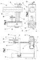
- Figure 1 shows a schematic lateral vertical elevation of the device applied to a tyre changing machine;
- figure 2 shows a schematic plan view from above of the device;
- figure 3 shows a section made according to line III-III of figure 2, with the retaining organ represented in two different operative configurations.
-
- With reference to the above-mentioned figures of the drawings, 1 denotes in its entirety a self-centring platform, with a vertical rotation axis x, applied on a frame of a tyre changing machine 2 of known type. The self-centring platform 1 is equipped with the usual fasteners for constraining vehicle wheel rims thereto. The
tyred rim 3 of a motor vehicle wheel 4 can be positioned, centred and constrained on the platform. - A
safety device 5 is associated to the platform 1 for constraining a wheel 4 placed thereon. Thesafety device 5 serves especially to prevent the wheel 4 from being unleashed violently away from the platform 1 following an explosion of the tyre during inflation thereof. - The
safety device 5 comprises an upright 6, vertically extending above the level of the self-centring platform 1, which might for example be one of the uprights normally present in the frame of the tyre-changing machine. Ahorizontal arm 7 is constrained to the upright 6, whicharm 7 can perform a rotating movement about a vertical axis which is parallel and close to the axis of the upright 6, so that thearm 7 can be positioned along a horizontal plane situated above the self-centring platform 1. Thearm 7 is constained to the upright 6 with a flag-type rotatable connection. - A
cylindrical stem 8 with a vertical sliding axis is slidably coupled to thearm 7. Thearm 7 can assume a position in which thestem 8 is coaxial or nearly so with the platform 1. The lower end of thestem 8 exhibits aplate 9, usually circular but which could be any shape, destined to interact contactingly with the central part of thewheel rim 3 located on the platform 1. In the illustrated example the lower surface of theplate 9 exhibits a downwards-directed convexity; concave or flat plates could be used instead, however. - The
stem 8 can slide vertically in both directions with respect to the arm 7 (as indicated by arrows 10) and can be made solid to thearm 7 itself only in a case where theplate 9, placed at the lower end of thestem 8 and interacting contactingly with the wheel 4, is for any reason solicited to move upwards. - When such a situation arises the
stem 8 is made automatically solid to thearm 7 and thedevice 5 can prevent the wheel 4 from lifting from the platform 1, a situation which would in fact arise should a tyre explode. - The
stem 8 is freely slidable with respect to thearm 7 in a downwards direction. - The means for immobilizing the
stem 8 with respect to thearm 7 comprise a plate-shapedretaining organ 11, having afirst hole 12 which, in the example illustrated is hexagonal, in which hole 12 arod 13 solidly constrained to thearm 7 is inserted with a predetermined degree of play. Therod 13, which also exhibits a hexagonal straight section, extends in a parallel direction to the sliding axis of thestem 8, which in the illustrated example is vertical. - The
retaining organ 11 exhibits a first end which is constrained to thestem 8 and able to to assume a first and lower locking position A (indicated by an unbroken line in figure 3) in which it prevents thestem 8 from sliding uwards due to the contact between therod 13 and the surface of theretaining organ 11 which surrounds thefirst hole 12. This position A is the characteristic locking position of a locking mechanism of the type achieved by what is commonly called a retaining lever. Theretaining organ 11 is brought into locking position A thanks to its own weight. - The
retaining organ 11 can further assume, if lifted, at least one other position, an unlocking position or upper position B (shown in a broken line in figure 3), in which a free axial sliding of thestem 8 is allowed i.e. sliding of the stem in an upwards direction. - A
striker element 14, solidly constrained to thestem 8, is predisposed to limit the upwards rotations of theretaining organ 11 with respect to thestem 8. Thestriker element 14 serves in substance to prevent the retainingorgan 11 from being tilted upwards to reach the locking position on thevertical rod 13 by a raising of theretaining organ 11 itself. Thestriker element 14, which in the illustrated case is constituted by a screw, is conformed and arranged so as to lock theretaining organ 11 in position B, i.e. the unlocked position. The position of thestriker element 14 can be regulated by a simple screwing or unscrewing operation. In another embodiment, not illustrated, two striker elements could be provided, operatively associated with theretaining organ 11 and able to stop it in unlocked position B (horizontal or more or less so), which striker elements could be set side-by-side and spaced one from the other, and preferably arranged on opposite sides with respect to the vertical plane constituted by the axes of thestem 8 and therod 13. - The
retaining organ 11 exhibits a second end, opposite to the first, which is associable to external movement means 1 with which theretaining organ 11 can be raised into the unlocking position B. In the illustrated case theretaining organ 11 is moved manually, the second end thereof exhibiting agrip 15. - The
retaining organ 11 exhibits asecond hole 16, circular in shape, in which thestem 8 is inserted with ample play. In the embodiment illustrated, theretaining organ 11 is hinged to thestem 8 about apivot 17, which is situated inside thesecond hole 16 and which is provided with a horizontal axis which is incident or nearly so with the axis of thestem 8. Theretaining organ 11 might exhibit, in place of thesecond hole 16, a fork-shaped end. The retaining organ could be constrained to thestem 8 by means of different-type connections to the one illustrated in the accompanying figures, such as for example connections at present used for retaining lever mechanisms commonly in use. - The
safety device 5 is provided with an angular position sensor, of known type and not illustrated, for reading the angular position of the horizontal rotatingarm 7, and which sends a consent signal to the tyre inflating means only when thestem 8 is substantially coaxial with the rotation axis x of the platform 1. The above-mentioned sensor has the task of guaranteeing that the inflation operation is carried out only when thesafety device 5 has effectively locked the wheel 4 in position. - As mentioned above, the
safety device 5 is useful when a tyre of a wheel 4 placed on the platform 1 is to be inflated; otherwise the rotatingarm 7 of thedevice 5 is normally positioned away from the platform 1 of the tyre-changing machine 2, so as not to get in the way during other operations which have be performed on the wheel. - The
safety device 5 is now described. Before inflating the tyre, the operator grips the second end of theretaining organ 11, pulling it upwards so as to bring theorgan 11 into unlocked position B in which thestem 8 can be slid upwards. Then the operator rotates thearm 7 of thedevice 5, with thestem 8 raised, up until thestem 8 itself and therelative plate 9 are positioned above the central zone of therim 3 of the wheel to be inflated. Then the operator lets go of thegrip 15 and theretaining organ 11 falls into position A by virtue of its own weight. In this configuration, any upwards solicitation on thestem 8, due for example to an explosion of the tyre, would be contrasted by thevertical rod 13 on thearm 7, whichrod 13 prevents clockwise movements (see figure 3) of theretaining organ 11. Thesafety device 5 in substance functions as a mechanism commonly known as a retaining lever. The unlocking of thedevice 5 is simply achieved by gripping theretaining organ 11 by thegrip 15 and lifting it into unlocked position B.
Claims (10)
- A device for constraining a wheel (4) and tyre assembly on a platform (1), comprising:characterised in that said means for immobilizing comprise a retaining organ (11) provided with a first hole (12) in which a rod (13) is inserted with a predetermined degree of play, said rod (13) being solidly constrained to the arm (7) and being lengthwise arranged parallel to the sliding axis of the stem (8); said retaining organ (11) exhibiting a first end which is constrained to the stem (8) in such a way as to be able to assume at least a lower locked position (A), in which the retaining organ (11) prevents an upwards sliding of the stem (8), and an upper unlocked position (B), in which the stem (8) can move upwards; this being achieved through contact between the rod (13) and the surface of the retaining organ (11) which surrounds the first hole (12); said retaining organ (11) exhibiting a second end, opposite to the first end, which second end is associable to external movement means with which the retaining organ (11) is raised into the unlocked position (B).an upright (6), vertically extending above the platform (1);an arm (7), constrained to the upright (6) and able to make a rotation movement on to a horizontal plane situated above the platform (1);a stem (8) coupled slidingly to the arm (7) and having a vertical sliding axis, said arm (7) being able to assume a position in which the stem (8) is coaxial with the platform (1), a lower end of the stem (8) being destined to interact contactingly with the wheel (4);means for immobilizing the stem (8) in a releasable fixed position with respect to the arm (7), said fixed position being such that the lower end of the stem (8) interacts with the wheel (4), in order to prevent the wheel (4) from lifting from the platform (1);
- The device of claim I, characterised in that it comprises at least one striker element (14), solidly constrained to the stem (8) and predisposed to limit the upwards rotations of the retaining organ (11) with respect to the stem (8), conformed and arranged in such a way as to lock the retaining organ (11) in the unlocking position (B).
- The device of claim 2, characterised in that a position of the striker element (14) can be regulated.
- The device of any one of the preceding claims, characterised in that it is applied to a self-centring platform (1) having a vertical axis of a tyre changing machine (2).
- The device of any one of the preceding claims, characterised in that it comprises a sensor for reading an angular position of the arm (7) and for providing a consent signal to means for inflating the tyre only when the stem (8) is coaxial to the platform (1).
- The device of any one of the preceding claims, characterised in that the retaining organ (11) is hinged to the stem (8) and can rotate about a horizontal axis.
- The device of claim 6, characterised in that the rotation axis is incident to an axis of the stem (8).
- The device of any one of the preceding claims, characterised in that the retaining organ (11) can be manually raised by means of a grip (15) associated to the second end of the retaining organ (11).
- The device of any one of the preceding claims, characterised in that said arm (7) is rotatably constrained to the upright (6) through a flag-type connection.
- The device of any one of the preceding claims, characterised in that the stem (8) is freely slidable with respect to the arm (7) for downwards-directed movements.
Applications Claiming Priority (2)
| Application Number | Priority Date | Filing Date | Title |
|---|---|---|---|
| ITMO970135 | 1997-07-18 | ||
| IT97MO000135A IT1294900B1 (en) | 1997-07-18 | 1997-07-18 | DEVICE FOR LOCKING A WHEEL WITH A TIRE TO A PLATFORM. |
Publications (3)
| Publication Number | Publication Date |
|---|---|
| EP0891882A2 EP0891882A2 (en) | 1999-01-20 |
| EP0891882A3 EP0891882A3 (en) | 1999-04-07 |
| EP0891882B1 true EP0891882B1 (en) | 2003-08-06 |
Family
ID=11386388
Family Applications (1)
| Application Number | Title | Priority Date | Filing Date |
|---|---|---|---|
| EP98830240A Expired - Lifetime EP0891882B1 (en) | 1997-07-18 | 1998-04-22 | A device for constraining a wheel and tyre assembly on a platform |
Country Status (4)
| Country | Link |
|---|---|
| US (1) | US6065522A (en) |
| EP (1) | EP0891882B1 (en) |
| DE (1) | DE69816918T2 (en) |
| IT (1) | IT1294900B1 (en) |
Families Citing this family (4)
| Publication number | Priority date | Publication date | Assignee | Title |
|---|---|---|---|---|
| IT1310201B1 (en) * | 1999-03-31 | 2002-02-11 | G S Srl | DEVICE TO FACILITATE DISASSEMBLY AND ASSEMBLY OF TIRES. |
| US8307874B1 (en) | 2008-01-25 | 2012-11-13 | Hunter Engineering Company | Tire changing method and machine with angularly positionable drive axis |
| CN111590354B (en) * | 2020-06-03 | 2021-08-06 | 重庆世茂机械制造有限公司 | Aluminum alloy fixing device with outer wall clamped and inner wall supported |
| CN117260648A (en) * | 2023-09-04 | 2023-12-22 | 一汽解放汽车有限公司 | Cylinder block turning device and turning method |
Family Cites Families (3)
| Publication number | Priority date | Publication date | Assignee | Title |
|---|---|---|---|---|
| IT1063154B (en) * | 1979-05-08 | 1985-02-11 | Mondolfe Femme S P A | DEVICE FOR REMOVING TIRES FROM WHEEL RIMS FOR CARS, MOTORCYCLES AND SIMILARS |
| TW343179B (en) * | 1995-10-02 | 1998-10-21 | Maciss R L | Burst protection device for tire removing machines a burst protection device for tire removing machines of the type having a platform on which a wheel can be located and an arm supporting a bead extractor. |
| IT1287640B1 (en) * | 1996-05-03 | 1998-08-06 | Corghi Spa | MACHINE FOR THE ASSEMBLY AND DISASSEMBLY OF TIRES ON AND FROM THE RESPECTIVE RIMS |
-
1997
- 1997-07-18 IT IT97MO000135A patent/IT1294900B1/en active IP Right Grant
-
1998
- 1998-04-22 DE DE69816918T patent/DE69816918T2/en not_active Expired - Fee Related
- 1998-04-22 EP EP98830240A patent/EP0891882B1/en not_active Expired - Lifetime
- 1998-04-23 US US09/064,313 patent/US6065522A/en not_active Expired - Lifetime
Also Published As
| Publication number | Publication date |
|---|---|
| DE69816918T2 (en) | 2004-07-15 |
| ITMO970135A1 (en) | 1999-01-18 |
| ITMO970135A0 (en) | 1997-07-18 |
| IT1294900B1 (en) | 1999-04-23 |
| DE69816918D1 (en) | 2003-09-11 |
| EP0891882A2 (en) | 1999-01-20 |
| US6065522A (en) | 2000-05-23 |
| EP0891882A3 (en) | 1999-04-07 |
Similar Documents
| Publication | Publication Date | Title |
|---|---|---|
| US4827742A (en) | Security assembly for vehicle roofrack | |
| US5638710A (en) | Method for securing a spare tire | |
| US3613972A (en) | Spare tire bracket apparatus | |
| US5464314A (en) | Device for handling a vehicle wheel | |
| US5199287A (en) | Security device for securing a spare tire | |
| US4765387A (en) | Tire changer safety foot | |
| US6065522A (en) | Device for constraining a wheel and type assembly on a platform | |
| GB2091182A (en) | Vehicle tyre security appliance | |
| EP0805053B1 (en) | Machine for mounting and removing tyres onto and from respective wheel rims | |
| US4846239A (en) | Tire changing machine with locking center post | |
| US10179615B2 (en) | Apparatus, system, and related methods for holding and maneuvering an industrial vehicle spare tire | |
| US5363897A (en) | Tubeless tire demounting tools | |
| US4840215A (en) | Tire changer safety post | |
| US6276422B1 (en) | Device for facilitating tire fitting and removal | |
| US4811774A (en) | Tire Changer safety arm | |
| CA1296247C (en) | Tire changer safety arm | |
| US6173751B1 (en) | Burst protection device for tire removing machines | |
| JP2000318538A (en) | Wheel holder | |
| US5222640A (en) | Spare tire mount for pickup trucks | |
| EP0915779B1 (en) | Locking mechanism for tow truck wheel lift | |
| JP3841966B2 (en) | Hose car lifting device | |
| CZ4876U1 (en) | Automobile wheel lockable device | |
| KR100202510B1 (en) | Tire lifting device for measuring wheel balances | |
| US5971053A (en) | Safety restraint and barrier for use with tire servicing equipment | |
| JPH0726167Y2 (en) | Fixture for tire anti-skid device |
Legal Events
| Date | Code | Title | Description |
|---|---|---|---|
| PUAI | Public reference made under article 153(3) epc to a published international application that has entered the european phase |
Free format text: ORIGINAL CODE: 0009012 |
|
| AK | Designated contracting states |
Kind code of ref document: A2 Designated state(s): DE ES FR GB IT |
|
| AX | Request for extension of the european patent |
Free format text: AL;LT;LV;MK;RO;SI |
|
| PUAL | Search report despatched |
Free format text: ORIGINAL CODE: 0009013 |
|
| AK | Designated contracting states |
Kind code of ref document: A3 Designated state(s): AT BE CH CY DE DK ES FI FR GB GR IE IT LI LU MC NL PT SE |
|
| AX | Request for extension of the european patent |
Free format text: AL;LT;LV;MK;RO;SI |
|
| 17P | Request for examination filed |
Effective date: 19990316 |
|
| AKX | Designation fees paid |
Free format text: DE ES FR GB IT |
|
| RAP1 | Party data changed (applicant data changed or rights of an application transferred) |
Owner name: G.S. S.R.L. |
|
| 17Q | First examination report despatched |
Effective date: 20010627 |
|
| GRAG | Despatch of communication of intention to grant |
Free format text: ORIGINAL CODE: EPIDOS AGRA |
|
| GRAG | Despatch of communication of intention to grant |
Free format text: ORIGINAL CODE: EPIDOS AGRA |
|
| GRAH | Despatch of communication of intention to grant a patent |
Free format text: ORIGINAL CODE: EPIDOS IGRA |
|
| GRAH | Despatch of communication of intention to grant a patent |
Free format text: ORIGINAL CODE: EPIDOS IGRA |
|
| GRAA | (expected) grant |
Free format text: ORIGINAL CODE: 0009210 |
|
| RAP1 | Party data changed (applicant data changed or rights of an application transferred) |
Owner name: SNAP-ON EQUIPMENT S.R.L. |
|
| AK | Designated contracting states |
Designated state(s): DE ES FR GB IT |
|
| PG25 | Lapsed in a contracting state [announced via postgrant information from national office to epo] |
Ref country code: FR Free format text: LAPSE BECAUSE OF FAILURE TO SUBMIT A TRANSLATION OF THE DESCRIPTION OR TO PAY THE FEE WITHIN THE PRESCRIBED TIME-LIMIT Effective date: 20030806 |
|
| REG | Reference to a national code |
Ref country code: GB Ref legal event code: FG4D |
|
| REF | Corresponds to: |
Ref document number: 69816918 Country of ref document: DE Date of ref document: 20030911 Kind code of ref document: P |
|
| PG25 | Lapsed in a contracting state [announced via postgrant information from national office to epo] |
Ref country code: ES Free format text: LAPSE BECAUSE OF FAILURE TO SUBMIT A TRANSLATION OF THE DESCRIPTION OR TO PAY THE FEE WITHIN THE PRESCRIBED TIME-LIMIT Effective date: 20031117 |
|
| PGFP | Annual fee paid to national office [announced via postgrant information from national office to epo] |
Ref country code: GB Payment date: 20040421 Year of fee payment: 7 |
|
| PGFP | Annual fee paid to national office [announced via postgrant information from national office to epo] |
Ref country code: DE Payment date: 20040429 Year of fee payment: 7 |
|
| PLBE | No opposition filed within time limit |
Free format text: ORIGINAL CODE: 0009261 |
|
| STAA | Information on the status of an ep patent application or granted ep patent |
Free format text: STATUS: NO OPPOSITION FILED WITHIN TIME LIMIT |
|
| 26N | No opposition filed |
Effective date: 20040507 |
|
| EN | Fr: translation not filed | ||
| PG25 | Lapsed in a contracting state [announced via postgrant information from national office to epo] |
Ref country code: GB Free format text: LAPSE BECAUSE OF NON-PAYMENT OF DUE FEES Effective date: 20050422 |
|
| PG25 | Lapsed in a contracting state [announced via postgrant information from national office to epo] |
Ref country code: DE Free format text: LAPSE BECAUSE OF NON-PAYMENT OF DUE FEES Effective date: 20051101 |
|
| GBPC | Gb: european patent ceased through non-payment of renewal fee |
Effective date: 20050422 |
|
| PGFP | Annual fee paid to national office [announced via postgrant information from national office to epo] |
Ref country code: IT Payment date: 20140423 Year of fee payment: 17 |
|
| PG25 | Lapsed in a contracting state [announced via postgrant information from national office to epo] |
Ref country code: IT Free format text: LAPSE BECAUSE OF NON-PAYMENT OF DUE FEES Effective date: 20150422 |